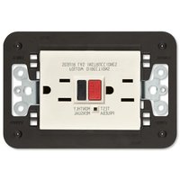
30296 - Wall socket Vimar - Free user manual and instructions
Find the device manual for free 30296 Vimar in PDF.


| Type | Wall socket |
| Brand | Vimar |
| Model | 30296 |
| Series | Vimar Arké or similar |
| Voltage Rating | 230 V AC |
| Current Rating | 16 A |
| Number of Sockets | 2 (dual socket) |
| Socket Standard | Type F (Schuko) / Type E (French) compatible |
| Material | Thermoplastic (UL94 V-0) |
| Color | White (typical) |
| Dimensions (W x H x D) | 85 mm x 85 mm x 40 mm |
| Weight | approx. 100 g |
| Mounting Type | Flush mounting (in-wall) |
| Terminal Type | Screwless terminals (push-fit) |
| Protection Class | IP20 (indoor use) |
| Safety Features | Child-resistant shutters |
| Standards | CE, RoHS, EN 60669-1 |
| Operating Temperature | -5°C to +40°C |
| Installation Depth | Min. 40 mm (flush box required) |
| Warranty | 2 years (manufacturer) |
| Compatible Accessories | Vimar frames, USB chargers, dimmers |
| Cleaning Instructions | Wipe with dry cloth; no solvents |
Frequently Asked Questions - 30296 Vimar
User questions about 30296 Vimar
0 question about this device. Answer the ones you know or ask your own.
Ask a new question about this device
Download the instructions for your Wall socket in PDF format for free! Find your manual 30296 - Vimar and take your electronic device back in hand. On this page are published all the documents necessary for the use of your device. 30296 by Vimar.
USER MANUAL 30296 Vimar
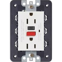
Double 2P+E 15A 125 V\~ 60 Hz socket outlet, American standard, with ground fault circuit interrupter (GFCI) and built-in mounting frame, to complete with 3-module cover plate.
DESCRIPTION.
A GFCI receptacle is different from conventional receptacles. In the event of a ground fault, a GFCI will trip and quickly stop the flow of electricity to prevent serious injury.
CHARACTERISTICS.
- Rated voltage 125 V–60 Hz.
- Rated current corresponding to the socket outlet standard 15 A.
• GFCI Class A (trip 6 mA or more).
Definition of a ground fault:
Instead of following its normal safe path, electricity passes through a person's body to reach the ground. For example, a defective appliance can cause a ground fault. A CFCI receptacle does not protect against circuit overloads, short circuits, or shocks. For example, you can still be shocked if you touch bare wires while standing on a non-conducting surface, such as a wood floor.
TEST YOUR WORK.
Why perform this test?
- If you miswired the GFCI, it may not prevent personal injury or death due to a ground fault. (electrical shock).
- If you mistakenly connect the LINE wires to the LOAD terminals, the GFCI will still operate like an ordinary receptacle, but it will not interrupt a ground fault.
Procedure:
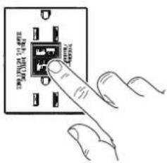
(a) This GFCI is shipped from the factory in the tripped condition and can not be reset until it is wired correctly and power is supplied to the device. Plug a lamp or radio into the GFCI (and leave it plugged in). Turn the power ON at the service panel. Press the RESET button fully, make sure the lamp or radio is ON. If the lamp or radio is still OFF or the RESET button can not be engaged, go to the Troubleshooting section because LINE and LOAD wiring connection have been reversed.
(b) Press the TEST button fully, the GFCI will trip and the lamp or radio will be OFF. To restore power, press the RESET button.
(c) If you installed your GFCI using CONNECTION B, plug a lamp or radio into surrounding receptacles to see which one(s), in addition to the GFCI, lost power when you pressed the TEST button. Do Not plug life saving devices into any of the receptacles that lost power. Place a "GFCI Protected" sticker on every receptacle that lost power. Then press the RESET button to reset the GFCI.
(d) Press the TEST button (then RESET button) every month to assure proper operation. If the GFCI can not be reset, then it must be replaced.
(e) If the GFCI consistently trips it indicates end of life and GFCI must be replaced.


TROUBLESHOOTING.
Turn the power OFF and check the wire connections against the appropriate wiring diagram in step CONNECTION A or CONNECTION B. Make sure that there are no loose wires or loose connections. Also, it is possible that you reversed the LINE and LOAD connections. LINE/LOAD reversal will be indicated by power remaining ON at the GFCI after you press the GFCI's TEST button. Reverse the LINE and LOAD connections if necessary. Start the test from the beginning if you rewired any connections to the GFCI.
CAUTION.
To prevent severe shock or electrocution always turn the power OFF at the service panel before working with wiring.
- Use this QFCI receptacle with copper or copper-clad wire. Do not use it with aluminum wire.
- Do not install this GFCI receptacle on a circuit that powers life support equipment because if the GFCI trips it will shut down the equipment.
Must be installed by a skilled person in accordance with national and local electrical codes.
FRONT VIEW BACK VIEW

CONNECTION A.

CONNECTION B.

PLACEMENT IN CIRCUIT:
The GFCI's place in the circuit determines if it protects other receptacles in the circuit.
SAMPLE CIRCUIT:

flowchart
graph TD
    A["Service Panel"] --> B["LINE"]
    B --> C["LOAD"]
    B --> D["LINE"]
    D --> E["LOAD"]
    D --> F["LINE"]
    F --> G["LOAD"]
    style A fill:#f9f,stroke:#333
    style B fill:#ccf,stroke:#333
    style C fill:#cfc,stroke:#333
    style D fill:#fcc,stroke:#333
    style E fill:#cff,stroke:#333
    style F fill:#ffc,stroke:#333
Placing the GFCI in position A will also provide protection to "load side" receptacles B and C. On the other hand, placing the GFCI in position C will not provide protection to receptacles A or B. Remember that receptacles A, B and C can be in different rooms.
Brand : Vimar
Model : 30296
Category : Wall socket