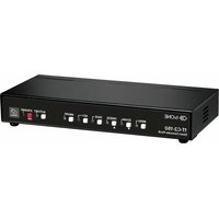
1T-C2-150 - Audio/video converter TV One - Free user manual and instructions
Find the device manual for free 1T-C2-150 TV One in PDF.


| Product Type | Down Converter PLUS / Audio/Video Converter |
| Model | 1T-C2-150 |
| Brand | TV One |
| Video Inputs | Composite (CV) via BNC, S-Video (YC) via 4-pin mini-DIN, RGB/YPbPr via HD15 |
| Video Outputs | Composite (CV) via BNC, S-Video (YC) via 4-pin mini-DIN, RGB/YPbPr via HD15 |
| Input Resolutions | Up to 2048x2048 (PC), up to 1080p (HDTV) |
| Output Resolutions | User selectable (e.g., NTSC, PAL, XGA, etc.) |
| Scaling Engine | CORIO®2 with 4:4:4 RGB/YUV sampling |
| Keyer | Chromakey (YUV) and Lumakey (Y) with adjustable range and softness |
| Picture-in-Picture (PIP) | Variable window size and position, single-button enabling |
| Genlock / Mixing | Genlock, Lock & Mix, Frame Lock modes; foreground/background swap |
| Control Methods | Front panel buttons, IR remote, RS-232 via D9, optional Windows Control Panel |
| Firmware Upgrade | Flash upgradeable via RS-232 (download from tvone.com/support) |
| Power Supply | External 12V DC @ 1A with locking center-pin connector |
| Dimensions (H x W x D) | 1.2 x 7.9 x 3.5 in (30 x 200 x 90 mm) |
| Weight (Net) | 1.3 lbs (580 g) |
| Operating Temperature | 0° to +45° C (+32° to +113° F) |
| Regulatory Compliance | FCC, CE, RoHS |
| Included Accessories | External power supply, IR remote control (varies by region) |
| Memory | Non-volatile settings storage |
| Zoom / Shrink Range | Zoom up to 10x (1000%), shrink down to 10% |
| Aspect Ratio Control | Simple, Advanced (independent H/V), Pixel (exact coordinates) modes |
Frequently Asked Questions - 1T-C2-150 TV One
User questions about 1T-C2-150 TV One
0 question about this device. Answer the ones you know or ask your own.
Ask a new question about this device
Download the instructions for your Audio/video converter in PDF format for free! Find your manual 1T-C2-150 - TV One and take your electronic device back in hand. On this page are published all the documents necessary for the use of your device. 1T-C2-150 by TV One.
USER MANUAL 1T-C2-150 TV One
General Topography 2
Ultimate flexibility....2
Simple Control 2
Upgradeability....2
Product images....2
Front panel controls.... 3
Button controls 3
MENU ↓ and ↑ buttons 4
Advanced menus 4
Special button combinations and functions 4
Locking front panel buttons & IR remote control 5
Restore power-on settings....5
Factory Reset 5
Switching units between different resolutions using the front panel....5
Video inputs and outputs....6
Computer and Video inputs 6
Computer and Video outputs 6
Infra-red remote control 7
Menu LAYOUT and SETTINGS Adjustment 7
Group Names and Descriptions 8
Items Associated with the Adjust outputs group 9
Items Associated with the Adjust windows group 12
Extended scaling controls.... 16
'Aspect adjust' = 'Advanced' 16
'Aspect adjust' = 'Pixel' 17
Items Associated with the Adjust keyers group 17
Items Associated with the Adjust sources group....19
Menu items common to all inputs 19
DVI Source Menu Items 22
RGB Source Menu Items....23
CV & YC Source Menu Items....24
Still Image Store / Testcard Source Menu Items 25
Items associated with the Adjust resolutions group 25
Important Cautionary Information 25
Items Associated with the System group 28
Serial port....31
Connection 31
Communications protocol....31
Serial / IP control specification....32
Communication protocol basics.... 32
Packet format....33
Function list....35
Examples....48
Reading and writing macros 49
Reading a previously stored Macro 50
Writing to a macro....51
Run and Restore macros....51
Emulate a front panel button press....52
Reset command....59
Common operations....59
Operation of the Keyer 59
Preparation: 60
Adjustment: 60
Troubleshooting and technical support....60
There is no picture on the Output....60
The image is shifted and not fully viewable....61
The output resolutions no longer appear as expected....61
There is excessive flicker on the Output. 61
The Output image is distorted....61
Some colors appear to be incorrect on the CV/YC output....61
How can I reduce color smearing on CV connections? 61
I can no longer adjust the Output image resolution. 61
The picture on the video display is black and white....61
The picture on the video display is green. 62
The RGB input is selected but the image is rolling or pink....62
The video signal from my DVD player does not appear to work....62
Image is flashing, snow is present, or source image does not appear....62
General troubleshooting checklist....62
Returning a product for repair 62
EMEA and Asia....63
All customers....63
Connector pinouts 64
HD15 connector....64
RS232 / D9 socket....64
4 Pin mini-DIN S-video connector (YC) input 64
Specifications....65
Video Inputs 65
Computer Input 65
Video Outputs (not present on all units)....65
Computer Outputs 65
Locking/Mixing....66
Scaling / sampling / memory 66
Regulatory Compliance....66
Environmental....66
Power Requirement 67
Control Methods....67
Accessories Included....67
Mechanical....67
Contact us....67
Welcome
Thank you for buying this 1T-C2 series product.
The 1T-C2 series uses the proprietary CORIO®2 Engine to perform its functions, being the second generation of the successful CORIO® products. The CORIO®2 technology is a powerful toolset for any application requiring high quality video signal conversion or image manipulation.
All units feature a single video processing and scaling engine, with some unit's also featuring video mixing, keying and fader capabilities.
These functions allow the flexibility for handling a wide range of inputs and outputs, depending on the unit used.
All units are at one in the home and broadcast & display environments. The 1T-C2 series offers a range of high-level image processing functions – with each model designed to fulfill a particular need.
The 1T-C2 series includes the following products.
1T-C2-100 Down Converter
Down converting an image is when a computer PC or HD input is inputted to the unit. The input signal is then converted into a suitable signal which can then be displayed for use on a video screen or television, such as composite video.
1T-C2-150 Down Converter PLUS
This unit has all the features of a Down Converter, but it also has the added facility to superimpose the inputted computer image on top of an existing video signal. This is achieved with the unit's inbuilt facilities such as Keying, Picture in Picture (PIP), and fading.
1T-C2-200 Video Scaler
This unit allows for a standard television video signal, such as Composite Video, to be input into the unit and then converted for use on a computer display. When using this function you can switch back to the computer image by pressing a button. This is known as bypass mode.
1T-C2-250 Video Scaler PLUS
Video Scaler Plus has all the features of the Video Scaler unit, but with the added facility of superimposing the converted video signal over the top of an existing computer video signal. This is achieved by using the unit's inbuilt features such as Keying, Picture in Picture (PIP), Fading, and the facility to switch between overlaying the foreground over the background and vice versa – background/foreground priority.
1T-C2-400 PC/HD Scaler
This unit allows computer / high-definition video scaling from one resolution to another – for example, 720p to 1080i, or VGA to XGA, etc. This unit does not have any overlay abilities.
Device Features
General Topography
4:4:4 RGB / YUV sampling provides full bandwidth color which allows precise keying where included in the units capabilities. This can be achieved through the keys on the front of the unit. Each unit's video inputs accommodate multiple video and computer signal formats and resolutions – see specifications at end of manual for full details.
Ultimate flexibility
The 1T-C2 series' output signal format flexibility assures that the Native Resolution of virtually any display can be matched. Because of the resolution calculator (included in the Windows® Control Panel), even new resolutions can be added to the unit. Signal parameter adjustments can be made for each video input and are stored in individual non-volatile memories for retrieval once the unit's power has been removed. The Video Scaler units employ pixel adaptive motion compensation to de-interlace fast moving images, and automatic 3:2 Pull-down efficiently de-interlaces video from 24 fps NTSC film.
Simple Control
The unit can be controlled in various ways. One option is to control it from the front panel using the keys on the front of the unit. Another option would be to control the unit from an infra-red remote control. It can also be controlled via RS-232 using the Windows Control Panel.
The Windows Control Panel is available for download from our Internet site and affords complete control of the unit and adds Scripting to facilitate long, complex sequence of commands.
Finally, a hardware based switcher like the CORIO®console unit allows the user to control the unit by mimicking a classic video switcher device.
Upgradeability
All 1T-C2 units benefit from firmware upgradeability, thus reducing product obsolescence by allowing the installation of the latest version of firmware. This not only applies to the software used to control the unit, but also to the range of resolutions stored inside the unit, the addition of new features, and upgrades to the heart of the image processing hardware – the CORIO®2 scaling engine. See http://www.tvone.com/support for more detail.
Product images
Your 1T-C2 product should look like one of the units below.


Front panel controls
The range of buttons on the front of the unit provides the user with quick access for selecting a variety of inputs and features. Since all the units in the 1T-C2 series are different, not all of the descriptions below will be applicable to the unit in question. The mostly notable are the MIX/KEY/FADE buttons that are on certain units only.
The MENU button, ↓ button, and ↑button set on the front panel provide the user with a way of navigating the on-screen-display (OSD) menu system. The RS232 interface and infra-red remote control also provide further ways of controlling the unit, which are detailed in a later section.
Button controls

A sub-set of the following buttons will be available on the front of the unit, depending on the model in use:
| Button | Button Function |
| MENU | Press once to show the on-screen display (OSD). Hold in to cancel the OSD. Hold in for longer to store the current settings. |
| ZOOM ↓ | Jumps to the ‘Zoom’ menu item (also steps Zoom between 100%, 150%, 200% and 300% if the OSD is not active) |
| FREEZE ↑ | Freezes the current image (does not affect any background image) |
| INPUT | Cycles through the inputs on the rear of the unit to use for image conversion - RGB, followed by CV, followed by YC, and back to RGB again. |
| FADE | Fades out the current image - fades back in on next press |
| KEY | Enables keying - see ‘Adjust keyers’ menu.(Key color defaults to black, so black foreground will disappear.) |
| MIX/PIP | Sets Lock mode to Lock & Mix, to overlay onto the current Lock source.Use with the KEY and FADE buttons for more flexibility.A 2^nd press will also activate PIP mode (this enables the Shrink value in ‘Adjust windows'). See ‘Adjust outputs’ menu details. |
| AUTOSET | Activates Autoset for the current analog RGB input |
| ASPECT | Cycles through 2 aspect ratio settings (letterbox and side-bars) before returning to ‘normal’. |
| STANDBY | Hold in to put the unit into Standby (power-save) mode.Hold in briefly to come out of Standby mode. |
MENU ↓ and ↑ buttons
The on-screen display (OSD) is controlled from the front panel by using these buttons. MENU will activate the OSD, whilst the ↓ and ↑ arrowed keys will allow different menu items to be selected and adjusted – this is detailed in a later section.
Advanced menus
System
Advanced menus
[Off]
The above menu item must be 'On' to activate certain menu items. These typically control the more advanced items in the menus.
Special button combinations and functions
Various button combinations are available to perform certain functions:
These buttons combinations only work when the unit is switched on and active i.e. with the STANDBY/ON LED off.
Locking front panel buttons & IR remote control
This can be performed by pressing STANDBY/ON and FREEZE at the same time. All front panel buttons and IR remote commands will be disabled, with the exception of repeating the above combination to unlock the unit and for storing the current locked buttons setting (thus letting you make sure the unit always starts up with the buttons locked). The IR remote's LOCK and STORE buttons will always be active, giving another way to turn button/IR remote locking off.
The STANDBY/ON button will flash when the unit's buttons are locked.
Should your current settings not allow you to see the on-screen display (OSD), restoring the last-saved settings might be useful. This can be done by pressing STANDBY/ON and MENU at the same time until a single beep is heard.
Factory Reset
If you wish to restore all operational parameters to their original condition (for example, if saved settings prevent the unit from working with your display monitor), hold the STANDBY/ON and MENU buttons in together until at least two beeps are heard.
All stored settings except resolutions are lost when the unit is reset. A Firmware update is the only way to perform a complete factory reset (including resolution data).
Switching units between different resolutions using the front panel
Down converters will default to outputting NTSC after a Factory Reset, whilst Video and PC/HD Scalers will default to outputting XGA (1024x768 @ 60Hz).
Should your display or output device not support the default resolution, or if you wish to have quick access to an alternate resolution, the following button combinations below can be used.
For example, press MENU & FREEZE together on the 1T-C2-100 to select PAL. When you are happy with the output resolution selected, press and hold the MENU button in to store the current settings.
Please note that these changes will have no immediate effect if LOCK or MIX buttons are illuminated, as this means that the output resolution is locked to the Lock source.
| Unit: | 1T-C2-1001T-C2-150 | 1T-C2-2001T-C2-250 | 1T-C2-400 |
| MENU-ZOOM | NTSC(Default) | Not used | 480p |
| MENU-FREEZE | PAL | Not used | 720p |
| MENU-INPUT | Not used | XGA(Default) | XGA(Default) |
Video inputs and outputs
The units have different video inputs and outputs depending on your model, and with the PC/HD output being either scaled, or just as a loop-through from the PC/HD input.


Computer and Video inputs
The PC/HD input can accept:
Analog RGBHV
RGsB (sync on green)
RGBS (composite sync at TTL levels)
YUV/YPbPr (including tri-level)
In most cases, the particular input being used will be auto-detected. See 'Adjust sources' for more information on manually selecting an input type. On some units such as Video Scalers, the PC/HD input is there just to pass a PC signal through to the monitor in 'bypass' mode.
CV and YC inputs can accept either standard NTSC or PAL inputs – for example, from a video camera, VCR, DVD player, gaming device, etc. PAL and NTSC detection is automatic.
Computer and Video outputs
The units have a number of different outputs depending on the function of the unit – see earlier front and rear panel diagrams to see what is available on your unit.
The PC/HD output can use:
Analog RGBHV
RGsB (sync on green)
RGBS (separate sync at TTL levels)
YUV/YPbPr (including tri-level).
However, note that on some units such as Down Converters, the PC/HD output is there just to loop the PC image through to the PC monitor. On Video and PC/HD Scalers, bypass mode (with the unit in Standby) will feed PC/HD input to the PC/HD output directly.
CV and YC outputs always function simultaneously and can be set to either standard NTSC or PAL – see 'Adjust outputs' for more information
Infra-red remote control
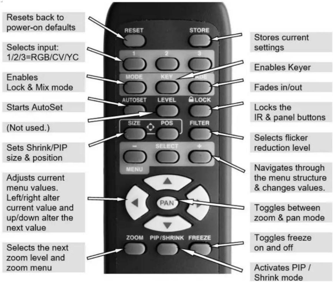
The transmit range of the remote control depends on many factors, but is designed to be fairly directional. Therefore you should always aim it directly towards your unit.
The IR remote control can be disabled in the System menu. This can be used in situations where multiple units respond to the same remote control or are located close to one another.
Menu LAYOUT and SETTINGS Adjustment
From here on, we'll be looking at the menu structure employed in the series and, more importantly, the individual menu items that allow you to take advantage of the power of the unit.
You'll be using the MENU ↓ and ↑ buttons and the on-screen display (OSD) to view the options and settings available to you. The OSD can be activated by pressing the MENU button once. Holding the MENU button in for a short while will then close the OSD.
Whilst the OSD is active, use the ↓ and ↑ buttons to change where you are in the menu. Go into a sub menu by pressing the MENU button once. To exit a sub menu, scroll using the ↓ or ↑ button to the end of the sub-menu to reveal Exit. Push in the MENU button to exit the sub menu.
You can edit a value in brackets '[ ]' by pressing the MENU button once (you'll note that the brackets surrounding a particular parameter's value will begin to flash). Change the value by using the ↓ and ↑
buttons to decrease and increase the value respectively. Then finalize your adjustment by pressing the MENU button once more.
A few menu items have multiple parameters within an individual menu selection. In those cases, you can adjust one item, and then move to the next, etc.
Holding the MENU button in for a few seconds stores all changes in memory. Unless you intentionally change it again later, the adjustment will remain even after power is removed from the unit.
Menus are arranged so that a particular general function has a menu name on the top line and beneath that either a sub-menu or one or more related individual settings are displayed.
In some cases the functionality is global – meaning it has an effect on the unit as a whole (such as changing the output resolution). In the majority of cases, the function is related to a specific operational area of the unit, detailed by the text in the top line.
There are two screens that appear before the Group Menus (sub-menus) are accessed.
CORIO2
TV One
The first is the 'welcome' display shown above indicating the model of the unit.
www.tvone.com
SW: 65. PT: 12, BT: 13
Moving to the next menu item displays the firmware information screen (the numbers on your unit will be different to those shown). The SW number refers to the version of firmware loaded into the unit, this can be upgraded from the support website.
The PT and BT numbers refer to Hardware version information and are of interest to the Technical Support Group should you ever need assistance.
At the end of all Group Menus will be an 'Exit' item. Simply select this to exit the existing menu structure and return to the previous one in the hierarchy.
Group Names and Descriptions
| Menu Group Name | Group Description |
| Adjust outputs | Controls output parameters |
| Adjust windows | Controls characteristics of the scaled window |
| Adjust keyers* | Controls the keying ability of the unit |
| Adjust sources | Controls signal source input parameters |
| Adjust resolutions | Controls unit's input/output resolution table |
| System | Controls global system parameters for the unit |
*Note that not all units have this menu item.
Note that the 'Advanced menus' menu item must be 'On' to activate certain menu items.
Items Associated with the Adjust outputs group
This menu group allows adjustments to be made that specifically affect the output of the unit, including output resolution and locking/overlaying onto a computer or video source.
800 x 600 60Hz
Lock mode
[Off] [RGB1]
This menu item allows the lock mode to be selected and the lock source to be defined. The top line of the display shows the current detected resolution of the selected lock source (RGB1 in this example). The lock mode can be either Off, Genlock or Lock & Mix, with the operation of these shown in the following table:
| Lock mode | Description |
| Off | The output resolution of the Output is defined by the setting for Output Resolution and there will be no background source visible. |
| Genlock | The output video will be “Genlocked” to the selected lock source. The output signal will be synchronous to the input sync and adjustable but there will still be no lock source visible. |
| Lock & Mix | The output video will be locked to the selected source, the syncs will be locked (but with an additional internal video processing delay) and the background for the output will be that of the Lock source (unless foreground and background are swapped). |
| Frm.lock* | The frame rate of the output will be locked to the frame rate of the input. This can only work if the output resolution frame rate matches that of the lock source frame rate. ‘Frm.lock’ will flash until a highly stable lock has been achieved. |
*Only certain models support this.
In both Genlock and Lock & Mix modes the source selected for the lock input determines the resolution of the output image. The output resolution for the entire image can be no different than the resolution of the lock source. All synchronization signals are re-generated within the unit so they may look slightly different when compared on an oscilloscope to the original source.
In Frame-lock mode, the output resolution is independent of the lock source, but the frame-rate must match that of the source (e.g. 1280x1024 60Hz can be frame-locked to 640x480 60Hz). Frame-lock is very useful for synchronizing a HD-SDI output (e.g. 1080i 59.94Hz) to a composite video source (e.g. NTSC), or for scaling one resolution to another while avoiding any potential frame-rate conversion artifacts.
'H/V shift' can be used to align the output to the input more accurately, but this may cause instability until the lock is re-acquired ('Frm.lock' will flash).
Before turning the Lock feature on, you first must select a valid Lock source. Some units may not have all Lock sources available, depending on hardware limitations – see Specifications for details of limitations on your unit.
If the Lock source you choose is not valid, then Genlock or Lock & Mix will be temporarily disabled, until the Lock source becomes valid again. When disabled, the resolution previously specified in 'Output res' becomes the output resolution.
1024 x 768 60Hz
Output res. [28]
Your unit can handle a very wide array of inputs and convert them all to a single output signal with defined characteristics. This output resolution will remain in place until changed or it may be overridden by the lock mode and source.
The top line of the display will show the current output resolution selected. Some units will have a limited number of output resolutions depending on their function (e.g. Down Converters are more limited than Video Scalers).
1024 x 768 60Hz
HDCP (Active) On
HDCP is handled only on certain units with DVI outputs, so this menu may not appear on your own unit. HDCP is a 'High-bandwidth Digital Content Protection' system, which can ensure that a high definition video signal cannot be received by units not equipped with a HDCP receiver.
This menu lets you see the current status of the output and whether HDCP is supported or active, and also lets you turn off the output's HDCP encryption system. Note, however, that turning HDCP off at the output will also prevent HDCP-encrypted signals from being received by the unit – see the table below.
By default, HDCP on the output is turned On - so that if your attached DVI display is HDCP-compliant, then your output will be encrypted (regardless of whether the input to the scaler is encrypted). Note that you don't have to attach a display to the output of the scaler – another unit can be connected instead, in which case that unit is known as a 'repeater'.
It is important to note that if your source is HDCP encrypted (for example, from a Blu-ray player) then you cannot output any un-encrypted signals that use this source (such as SDI, analog YPbPr, etc.). Only HDCP-encrypted DVI or HDMI can be output. Therefore if your source is encrypted then you must ensure that this HDCP setting is On and that your display is HDCP compatible.
Please also see the HDCP menu item in 'Adjust sources', as this controls availability of HDCP at the DVI input.
The status message given in brackets has the following meaning:
| Status message | Description | Effect |
| No display | There is no display attached (HOTPLUG is low). | Nothing will be output on the DVI connector. |
| Unavailable | The device attached is not capable of supporting HDCP. | As the DVI output cannot be HDCP encrypted, then a HDCP-encrypted source cannot be selected for scaling. |
| Supported | The device attached is capable of HDCP, but the output is not currently encrypted. | As the DVI output is not HDCP encrypted, then a HDCP-encrypted source cannot be selected for scaling. |
| Active | The device attached is capable of HDCP, and the output from the unit is encrypted. | As the DVI output is HDCP encrypted, then a HDCP-encrypted source can be selected for scaling. Note that no other output connector (SDI, CV, YC, YUV or RGBHV) will function – since they are not encrypted. |
| Rep. supprt | The repeater unit (e.g. scaler) attached is capable of HDCP, but the output is not currently encrypted. | As the DVI output is not HDCP encrypted, then a HDCP-encrypted source cannot be selected for scaling. |
| Rep. active | The repeater unit (e.g. scaler) attached is capable of HDCP, and the output from the unit is encrypted. | As the DVI output is HDCP encrypted, then a HDCP-encrypted source can be selected for scaling. Note that no other output connector (SDI, CV, YC, YUV or RGBHV) will function – since they are not encrypted. |
Adjust outputs
Output type
[RGBHV]
Adjust outputs
Anlog= [RGBHV]
Dig= RGBHV
This menu may appear as either of the above – depending on whether the analog and digital outputs are controlled separately.
This menu item allows you to select the type of signal output your unit will provide. Types of output vary depending on the resolution selected and include various types of component signals YUV or tIYUV (tri-level YUV) and the full range of RGB type signals RGBHV, RGBS and RGsB (Sync on green).
Note that this value is remembered for each resolution – so you can set 1024x768 60Hz to RGBHV and 1280x720 60Hz to tLYUV and both will be remembered separately. This value is not affected by a Factory reset – but is reset by a firmware update.
Adjust outputs
Optimize for SDI
[On]
This menu item is only available on certain units with an SDI output and when locking to a CV or YC input. An internal de-jitter circuit ensures that the SDI output has a low jitter over the full 10Hz to 100kHz range, even though the CV or YC input may have a high jitter. However, this is not always compatible with a CV/YC output where the colour sub-carrier should not be de-jittered and needs to follow a Lock source's input – hence it should be turned Off it the CV/YC outputs are going to be used.
Adjust outputs
Stand.
[NTSC-M/PAL-BDGHI]
This menu item is only available when the Output resolution is set to PAL or NTSC. With this you can change the output type to the PAL or NTSC standard with the further option of changing the output to
the additional PAL & NSTC standards such as PAL-M or PAL-N. SECAM is also available as an output on some units, provided the 'Output res' is set to PAL / 50Hz.
Adjust outputs
Luma/chr BW [Med] / [Med]
This menu item is only available on certain units when the Output resolution is set to PAL or NTSC. With this you can change the output filtering system to increase or decrease the image sharpness. In general, high sharpness can result in increased colour disturbance.
Adjust outputs
Back Y/U/V [16] [128] [128]
Sets the value of the fixed background color, which is present when PIP is used with no Lock source background displayed. This menu item is only available for units with overlay, keying and fading abilities.
Adjust outputs
Audio emb. [On] [DVI-U1]
For certain units with HDMI and/or SDI-compatible inputs and outputs, the audio can be de-embedded from the video signal and sent to a compatible output.
'On' enables this to happen, and allows the audio source to be selected. 'WinA' sets the audio source to follow that of the main window's video source.
Items Associated with the Adjust windows group
This menu group allows adjustment to be made to window specific parameters such as the window source, its position, size and zoom level.
Window size adjustment can be performed in a number of different ways according to whether 'Aspect adjust' is set to Simple, Advanced or Pixel. The main part of this text assumes Simple mode – see later for a detailed description of the other modes.
Adjust windows
Window to adjust [A]
This menu item only appears on units with multiple windows or PIPs. It is used to select which one you want to modify. Alternatively, use one of the dedicated buttons on the front panel to choose the window to adjust.
NTSC / 60Hz
Source [ YC1]
The source display screen allows the input source for the currently selected window to be changed. The top line of the display shows the detected characteristics of the signal. Valid Input sources match those available on the front of the unit.
Certain units do not have full flexibility of Window source and Lock source when Genlock or Lock & Mix are active (in the Adjust outputs menu group). See the Specifications for your unit to see if any limitations are present.
Adjust windows
Window enable [On]
Available on certain units only, this quickly enables or disables the window being adjusted.
Adjust windows
Zoom level % [100]
Changing this option, sets the amount of picture magnification you wish to use for the window Source. You are provided with the options to zoom the image from 100% to 1000% (10x zoom).
Adjust windows
H/V zoom pan % [50] [50]
Once an image has been 'zoomed', this control allows the image to be positioned within the window so that any portion can be seen, not just the middle.
Adjust windows
Image freeze [Off]
This menu item allows the image to be frozen or unfrozen – thus keeping a single image on screen indefinitely. Note that images are not stored when power is removed from the unit.
Adjust windows
H/V crop % [0] 0
This allows the scaled image to be cropped at the top/bottom edges, or at the sides. Typically, this is used when performing a picture-in-picture (PIP) function (only available on certain models), where the incoming video signal has a letterbox or pillarbox size (i.e. it has black areas at the top/bottom or sides).
By adjusting the H/V values, you can crop out the black areas to correct the size on the final output screen. Note that it does not change the shape or aspect ratio of the image – but just removes the parts of the image that are not required.
Adjust windows
H/V out shift [0][0]
This positions the selected Window horizontally and vertically on the monitor. This should only be used for 'fine tuning' and should not normally require adjustment – use the Shrink H/V adjustment when your image is less than 100% Shrink value.
Adjust windows
Shrink level% [50][On]
Shrink Level determines the percentage of the monitor's total available screen space that the selected Window image occupies. Adjustment is provided for a reduction down to 10% of the overall output size. In most cases, this feature is used for picture-in-picture (PIP) when a background image is being used (for units with overlay abilities).
Note that some units do not have the [On] entry – this is only for units with a PIP button on the front, with turns this entry On and Off. On these units, this feature is 'Off' by default, so that the full image size of 100% is used. Shrink level will need to be turned On before any change to this value has an effect.
Adjust windows
H/V position % [100] [50]
This menu option determines the position of the shrunken image on the monitor screen. This will move an image that is less than the full screen size left/right or up/down within the monitor's available screen space. It will not let you move the image off the screen, so certain values will appear to have no effect (unless you use a very low Shrink value like 10%).
Adjust windows
Aspect change [Normal]
This item provides a simple way of changing the output screen aspect ratio, to suit the incoming video signal and final output display size. Use the zoom/shrink functions for occasions when the aspect ratio is an odd format.
Adjust windows
Aspect adjust [Simple]
See later section for further details on this item.
Adjust windows
Temporal interp. [Off]
This is a feature only present in advanced units only. It greatly improves the method of frame-rate conversion, by allowing the unit to merge frames together during the process.
When 'Off', the unit will use frame-repetition when converting 50Hz to 60Hz (i.e. it has to duplicate every 5th frame), or frame-dropping when converting 60Hz to 50Hz (i.e. it has to drop every 6^th frame). When 'On', smooth blending is applied so that frames are not lost, but blended together at the appropriate times.
Adjust windows
Flicker Reduction [Low]
The Flicker Reduction menu item will only appear if you have selected a low resolution interlaced output such as PAL or NTSC. If you are using CV or YC outputs, this adjustment may be of interest, particularly when you have line drawings or similar fine detail. You can choose from four possible Flicker Reduction settings. You should use as little Flicker Reduction as possible because the Vertical detail will be softened at the highest setting.
| Flicker mode | Function |
| Off | Disables flicker reduction (sharpest mode). |
| Low | Suitable for most input sources. |
| Med. | Enough for most situations such as thin line drawings |
| High | Highest amount of flicker reduction. Will cause loss of vertical detail in some images. |
Adjust windows
Image smoothing
[Auto]
Image smoothing reduces the jagged-edges sometimes seen within an output image by softening it. It typically improves the quality of a scaled image greatly. There are four possible settings for this adjustment: "Off", "Med.", "High", and "Auto". The "Auto" setting is generally thought to be most desirable and will vary the smoothing process according to the amount of zoom taking place.
Adjust windows
Image flip
[Off]
Occasionally, it's necessary to cause the output image to be flipped Vertically, Horizontally or both – most commonly when a video projector is ceiling-mounted, or for special effects.
Adjust windows
Show source label
[On]
Units that support source labeling have this menu item available, which allows the label to be turned on or off on a window-by-window basis.
Adjust windows
Audio bars
[4]
Certain units can display audio bar measurements and this menu item displays how many stereo-bars are shown. A maximum of 4 stereo bars (8 bars in total, with left-right pairs next to each other) can be shown. Audio channels are always numbered from left to right, balanced to display bars on both sides of the each. A setting of 0 disables the audio bars from being shown.
Adjust windows
Max fade level %
[100]
This Menu item fades the selected layer, and is only available on models with overlay abilities. Adjustment range is from solid to fully transparent.
Note: This menu item only appears on multi-channel scalers:
Adjust Windows
Layer priority abABZ [3]
This adjustment selects the order of the window layers. Layers are shown for 'a' and 'b' logo screens, Window 'A', Window 'B' and 'Z' is the Lock Source. The default condition is shown. The number shown is the current layer of the active window, when you adjust the layer number the layer stack indicator 'abABZ' will change to allow visualization of the layer stack. Note that layer 6 the Background Color is not shown as its layer position can not be altered – it will always be the background.
Extended scaling controls
The 'Aspect adjust' parameter is used to change the way that scaling of windows is controlled. By default it is set to 'Simple' which allows basic control of the window zoom and shrink sizes and positions – enough for simple tasks.
In 'Advanced' mode, it allows the horizontal (H) and vertical (V) components of the Zoom and Shrink functions to be adjusted independently, thus allowing custom aspect ratios to be created, or to convert from one aspect ratio to another.
In 'Pixel' mode, the user has direct access to pixel and line-accurate scaling functions. This lets the user specify the exact co-ordinates and size of the source image (within the video source), and the position and size of where this is placed in the output video signal.
The table below summarizes the different menu items in the different modes – the 'Simple' items have already been described earlier in this section, so only the 'Advanced' and 'Pixel' ones that are different (highlighted in bold) will be detailed here.
| Simple | Advanced | Pixel |
| Zoom level % [100] | Zoom H/V [100]100 1.333:1 | In [0],0 640,480 |
| H/V zoom pan% [50] 50 | H/V zoom pan% [50] 50 | Out [0],0 640,480 |
| H/V crop % [0] 0 | H/V crop % [0] 0 | |
| Shrink level % [50] Off | ShrnkH/V [50] 50 1.333:1 | |
| H/V position % [50] 50 | H/V position % [50] 50 |
'Aspect adjust' = 'Advanced'
Adjust windows
H/V zoom % [100] [100] 1.333:1
This item allows the independent setting of the horizontal and vertical zoom values. The third number (1.333 in the example) is the Aspect Ratio resulting from the adjustments, which is automatically calculated for you based on the incoming resolution and the H & V Zoom values.
Most resolutions are 4:3 ratio, thus the third number will be 1.333 (4 divided by 3). Another common aspect ratio is 16:9 (16 divided by 9 = 1.777). PAL and NTSC inputs are physically 4:3 on your video monitor, but their actual pixel/line ratios are different and so will not display as 1.333.
Adjust windows
Shrink H/V % [100] [100] 1.333
This item allows the setting of different Horizontal and Vertical 'shrink' sizes. The third number (1.333 in the example) is the Aspect Ratio resulting from the adjustments, which is automatically calculated for
you based on the output resolution (the actual pixels & lines, not your physical screen size) and the H & V Shrink values.
Most resolutions are 4:3 ratio, thus the third number will be 1.333 (4 divided by 3). Another common aspect ratio is 16:9 (16 divided by 9 = 1.777). Therefore, to convert your 4:3 output into a 16:9 output, reduce the vertical (V) Shrink value to 75% and this will simulate a 16:9 output. PAL and NTSC inputs are physically 4:3 on your video monitor, but their actual pixel/line ratios are different and so will not display as 1.333.
'Aspect adjust' = 'Pixel'
| Adjust windowsIn [300], 150 750, 400 |
| Adjust windowsOut [50], 50 250, 300 |
These menu items work together to specify the exact co-ordinates and size of the source image (within the video source) and the position and size of where this is placed in the output video signal – in other words the 'In' and 'Out' positions and sizes.
The diagram below should help to clarify the function of these values:

flowchart
graph TD
    A["IN"] -->|0| B["OUT"]
    A -->|768| B
    B -->|0| A
    style A fill:#f9f,stroke:#333
    style B fill:#ccf,stroke:#333
In the example above, 'In' has been set to 300,150 as its top-left source co-ordinate, with a size of 750,400. 'Out' has been set to 50,50 (i.e. close to the top left) with a size of 250,300.
The scaler will then ensure that the whole of the source (of size 750 by 400) is scaled to the required output (of size 250 x 300).
Items Associated with the Adjust keyers group
Please note that not all units have this sub-menu – it is only present on units with overlaying abilities.
Towards the end of this manual you will find a section titled 'COMMON OPERATIONS' – this gives a step-by-step guide to keying out a particular color.
Adjust keyers
Keyer enable
[Off]
This menu item turns keying On or Off for the current foreground. A keyed image is in essence one image superimposed over another – such that portions of the top image are made transparent (keyed out), so that the background image can show through. The following settings allow you to vary the colour(s) that are keyed out.
Adjust keyers
Swap fore/backgrnd [Off]
This menu item is only present on single-channel scalers – dual and quad-channel scalers have the layer priority set within the 'Adjust Windows' menu.
This menu item allows you to swap the foreground and background images when Lock mode is set to Lock & Mix. It will have no effect in any other mode (since no background is present).
Normally, your foreground is the input (window) source and your background is the lock source. This then allows you to superimpose any graphics or video input on top of the lock source by keying out a certain color or range of colors in the input source. Swapping them means that the input source moves to the background and the lock source is now in front of it. Thus you are now keying out the lock source colors to reveal the input source behind it.
Note that this is different to simply swapping over the input and lock sources as that would affect the final output resolution – see examples below:
| Input source | Lock source | Swap | Foreground (keyed) | Background (non-keyed) | Output resolution |
| XGA | NTSC | Off | XGA | NTSC | NTSC |
| XGA | NTSC | On | NTSC | XGA | NTSC |
| NTSC | XGA | Off | NTSC | XGA | XGA |
| NTSC | XGA | On | XGA | NTSC | XGA |
(XGA is 1024x768)
You will see that the Swap between foreground and background has no effect on the output resolution as this is always set by the Lock source.
Adjust keyers
Y Key min/max [0] [32]
The Min/Max parameters are used to select what range of Y (luminance/grey-scale) values are made transparent within the selected window/lock source. In order to key out part of an image, start with the max value and increase it until the required lighter parts within the window/lock source disappear. Then adjust the min level to bring back any darker parts of the image.
Adjust keyers
Y Key softness [0]
The Y Key softness option removes noise from the keyed image, generally at the edges. Adjust as required to make the edges of the key as sharp or as soft as desired. The noise is where the analog to digital process (A/D conversion) may not sample a 50% brightness as being exactly 50% i.e. sometimes 49% and sometimes 51%. Increasing the softness value will broaden the range of keyed colors so that the keying of images varies depending on how close a color is to the keyed-out range.
Adjust keyers
Y Key invert [Off]
The Y Key invert changes the keying characteristics with respect to what colors of the foreground image you wish to 'key out'.
Setting it to Off will cause the colour range that's defined to be removed - remove the desired colors. Setting it to On will cause the colour range that's defined to be kept - key out all other colors.
The descriptions above behave identically on the remaining U Key Invert & V Key Invert component versions. However they are directed at the U/B-Y (blue) colour component and V/R-Y (red) colour components respectively. Adjustment and effects are the same as explained above for Y Key Invert (brightness/grey-scale).
Items Associated with the Adjust sources group
The 'Adjust Sources' menu group accesses the parameters associated with the processing amplifiers used for each input (RGB, CV, YC, etc.). They allow you to fine-tune an incoming signal to optimize its color, brightness or even sharpness.
Not all settings are available for all input types, and not all input types listed here may be available on your unit. Also note that many of these adjustments may not show without 'Advanced menus' set to On.
It is recommended that you Store your settings once you're happy with them in readiness for future use.
Source: RGB1
Source to adj
[RGB1]
This menu item selects the input connection for which you want to make adjustments to. As in the image above, changes will only be made to the source connected to RGB1. Once the selection has been made, all changes made using the following operating parameters will only apply to the selected input.
Selection of a CV/YC source will reveal different menu items that allow adjustments beyond those used for RGB sources. The menu discussions that follow relate first to RGB sources, then to CV / YC type sources.
Menu items common to all inputs
Source: RGB1
Aspect correct
[ Fill]
This menu item will be used to correct the aspect ratio of the video source when converted into the final output resolution. The following table details what happens in the available modes:
| Setting | Result |
| Fill (default) | The source is stretched to fill the output. |
| Aspect | The source's aspect ratio is maintained on the output. |
| H-fit | The source is stretched to fill the horizontal dimension of the output, with the vertical dimension stretched by the same amount (and possibly clipped). |
| V-fit | The source is stretched to fill the vertical dimension of the output, with the horizontal dimension stretched by the same amount (and possibly clipped). |
| 1:1 | Each source pixel is represented by a single output pixel – no scaling will be performed. If the input resolution is higher than the output, then only part of the source will be seen. If the input resolution is lower than the output, then a black border will be present. |
Source: RGB1
TL pos. adj.
[0][0]
This menu item allows manual positioning of the Top and Left portion of the image. It is used to ensure that the input signal is captured correctly, eliminating any black borders. These settings are often used to correct the position of a PC signal on an input, or to eliminate any undesired noise at the top or bottom of a PAL or NTSC video source.
Source: RGB1
BR size adj.
[0][0]
This menu item allows manual positioning of the Bottom and Right portion of the image. These settings are often used to correct the position of a PC signal on an input, or to eliminate any undesired noise at the top or bottom of a PAL or NTSC video source.
Source: RGB1
Audio input source
[1]
If your unit has an internal audio switcher / selector, this menu item selects the desired Audio input for use with the active video source, allowing an audio-follow-video function.
Source: RGB1
OPTION audio source
[1]
If an external audio switcher is connected via the OPTION bus, then this menu item selects the desired Audio input for use with the active video source, allowing an audio-follow-video function.
In most situations, the Audio input values would be different for each video source – so that when the first video source is selected, so is the first audio source (this is called 'audio follow video'). The second video source then selects the second audio source, etc. However, there is nothing to prevent all Audio input values being set to the same value, for 'audio breakaway'.
Source: RGB1
Audio
Vol [ 1] Bal [ 0]
This menu item adjusts the audio volume and balance for the selected audio channel. This is only functional for certain units when an optional Audio Switcher is attached.
Source: RGB1
On source loss
[Blue]
(This has replaced 'De-glitch' used on previous firmware versions.)
This option is used to tell the unit what to do if the video source is lost or becomes unstable. Options are:
| Option | Description |
| Show | Shows all picture break-up and instabilities. |
| Freeze | Freezes the latest frame - un-freezes as soon as the source becomes stable again. |
| Blue (default) | Turns the window blue, to represent source loss. |
| Black | Turns the window black. |
| Remove | Removes the window, thus showing any background (e.g. a Lock source). This is useful for MIX & PIP scenarios on units with overlay abilities. |
If you have a very unstable input, such as a video tape player with a poor (jumping) output signal, you may wish to turn the setting to 'Show'.
Source : RGB1
De-int
[M.comp med]
An interlaced input consists of two fields separated in time. Both fields are required in order to make up the full resolution input image, but since they are sent one after the other, a moving image will have "motion artifacts" if the two fields are simply combined together. The most common artifact is a blurring at the point of maximum movement within an image. Your unit provides some tools to minimize the effects of de-interlacing of an image.
The following options are available for this menu item:
| Mode | Function |
| Normal/weave | The two interlaced fields are simply combined/weaved together. This will often show artifacts on moving images, but can be used when the input is known to be still. |
| Auto | Automatically selects Film 3:2 or Medium Range Motion Compensation (M. Comp Med.) depending on whether Film Mode is detected or not. |
| Film 3:2 | Enables 3:2 pull down conversion of the incoming NTSC video. (This option should not be used if the source is not NTSC video). |
| M. Comp LowM. Comp Med.M. Comp High | Enables Pixel Adaptive Motion Compensation. Three levels are available with ‘Low’ providing the least compensation for Motion and ‘High’ providing the most compensation. |
| Frame/bob | The two fields are shown consecutively. |
Source : RGB1
Diagonal interp.
[Off]
This menu item allows the user to specify whether the source has diagonal interpolation applied to it when de-interlacing occurs. This reduces 'jagged' artifacts on moving images, however is not suitable for noisy sources where the noise could be mis-interpreted as a diagonal or sloping element of the picture.
Source : RGB1
Noise reduction
[Off]
This menu item allows the user to specify whether the source has noise reduction applied to it. This is performed by averaging the video signal over a number of fields – but ignoring areas where motion has occurred. If motion blurring is seen, it is recommended to turn this setting off.
DVI Source Menu Items
Source: DVI1
HDCP
[Inactive]
[Off]
HDCP is supported on certain units only - and only on the DVI input connector. This menu item lets you change whether HDCP is active on this particular DVI input.
If turned 'Off', then a source that requires HDCP encryption will not send a video signal to your unit.
If turned 'On', and a HDCP-compliant display or device is attached to your unit's DVI output, then HDCP encrypted sources can be used.
The following table summarizes the message given in brackets:
| Status message | Description | Effect |
| Inactive | HDCP is not active at the DVI connector. | HDCP-encrypted material cannot be received by the unit. |
| Active | HDCP is active at the DVI connector. | HDCP-encrypted material can be received by the unit, but only if a HDCP-compliant display or device is attached to the unit's output. |
See 'Adjust outputs' for a description of how the HDCP system works on your scaler.
Source: DVI1
Display emul. EDID
[DVI]
This feature is only present on certain units – it is used with the next menu item to form a simple 'EDID Manager'.
EDID is an information packet retrieved by a PC graphic card over a DVI link from a monitor which tells the graphic card which resolutions the display supports. In the case of your unit, it tells the graphic card what resolutions are compatible with it – by emulating a display.
The above menu lets the user select which of 8 EDID data blocks are 'shown' to a PC or other DVI/HDMI source. (It does not affect any other input.) Note that some graphic cards will usually only read the EDID data when the cable is first connected, or on power-up.
The 8 EDID blocks are as follows:
| EDID | Usage |
| Mem1 | User-definable - see 'EDID capture' |
| Mem2 | |
| Mem3 | |
| Mem4 | |
| Mem5 | |
| Mem6* | |
| HDMI* | Default HDMI EDID data for your unit |
| DVI | Default DVI EDID data for your unit |
| Mon | The attached monitor's EDID data |
*Your unit will have either Mem6 or HDMI, but not both.
If you change this value, you'll need to store your settings and then re-boot the CORIO2 unit at least once to ensure that the source sees that the EDID data has changed.
It should also be noted that some graphic cards will require your PC to be re-booted before they see that a change has occurred.
If your unit allows 'HDMI' to be selected, this can also enable certain audio features depending on the abilities of your unit.
Source: DVI1
EDID capture [1] Grab
This menu provides a simple way of capturing EDID data from an attached DVI or HDMI monitor and storing it in one of the user-definable EDID memory data blocks (Mem1 to Mem6) – see previous menu.
To capture a different display's EDID, perform the following:
- Connect that display to the DVI output of the CORIO2 unit - the CORIO2 unit will then read it automatically and store it in the 'Mon' EDID entry.
- Select which EDID memory (Mem1 to Mem6) to copy this information to.
- Select 'Grab' and click on it - this will copy the current monitor's information to that EDID memory.
- Change 'EDID to use' to that memory location (Mem1 to Mem6).
- Store your unit's settings (see earlier in this manual on how to do this).
- Re-boot (turn off and on again) the CORIO2 unit to ensure that the graphic card uses this new EDID data (you may need to re-boot your computer as well).
Using the above, up to 6 custom EDID settings can be stored in the CORIO2 unit, ready for recall later. This is useful to simulate another display being attached to a graphic card.
RGB Source Menu Items
Source: RGB1
Autoset status [Inactive]
Once the Autoset sense setting has been made, this menu item is accessed and activated. The Autoset sense utility will then correct the pixel phase and then position the Top Left portion of the image and the Bottom Right portion of the image. Once complete it then resume inactive status.
Source: RGB1
Input pixel phase [16]
Since an image pixel is a very small element of the total image, it's possible for your unit's Analog to Digital converters to wrongly sample the picture on the edge of each pixel thereby losing image resolution and creating image noise. The Input pixel phase adjustment allows you to change the position (from 0 to 31) where the pixels are sampled, relative to the horizontal sync signal.
To make this adjustment, select an RGB source and then provide an image from that source with fine detail, preferably with very sharp vertical lines. Adjust this value until you see the sharpest image. Alternately, adjust this value to give the worst (noisiest/softest) image, and then add or subtract 16 to get the optimum value.
Note that the AUTOSET function (for RGB inputs only) will attempt to automatically work out the best value for this setting.
Source: RGB1
RGB input type [RGBHV]
There are several types of signals that are called RGB signals as a generic term. Each has slightly different characteristics that set it apart from similar RGB signals – such as how the synchronization signal is sent. This menu item lets you set the input type to use.
Available options let you select whether the input is standard RGB or YUV (including YPbPr signals with a tri-level sync). For some units, it also allows selection of break-out BNC connectors to be used instead of the normal connector (signified by B- in front of the signal type).
Source: RGB1
RGB contr. [100] [100] [100]
This menu item lets you adjust the individual RGB or YUV/YPbPr signals, in case one component is at a different contrast to other, or if they all need to be boosted or lowered.
CV & YC Source Menu Items
Of the above Source Menu items, the Autoset sense and Autoset status functions, RGB type and Pixel phase are specific to RGB signals only. The rest of the Source menu items function with RGB, CV or YC type signals. In addition, there are four additional Menu items that are only used with CV or YC type signals and these are explained below:
Source: YC1
Bright [100] Contrast [100]
Adjust the Brightness and Contrast of the image to your requirement.
Source: YC1
Satur [100] Hue [0]
Saturation is the amount of color present in the image. Hue is the color "tint" parameter and the adjustment range is +90 degrees through to -90 degrees with 0 being the default.
Source: YC1
Sharpness
[0]
Within limits, you can enhance or soften the appearance of detail within an image. The Sharpness values go both negative and positive, with 0 being the default. Note that over-enhancing an image has the side effect of making it appear to be noisy and under-enhancing an image gives the appearance of poor video quality.
Source: YC1
Luma delay
[0]
On occasion, a video source will have the color portion of the signal offset from the luminance portion. If you've ever seen a poor quality comic book that has the outline of the cartoon character's head in one place on the page but the flesh tones for the head offset slightly, you are seeing the print equivalent of Luminance to Chrominance Phase Delay.
Fortunately, your unit provides a way for you to make the two signals occur at the same time on the selected image. The adjustment range provides both positive and negative levels of delay with 0 being the default.
Still Image Store / Testcard Source Menu Items
Source : TC1
Testcard
[0]
This item is only available for units supporting Still Image Stores (SIS) or Testcards (TC) – which are the same thing, but may be named differently depending on your unit.
Used to select the image from memory to use as a source for the SIS / TC source currently selected. Dedicated software can be used to upload user-defined images – see our website.
Items associated with the Adjust resolutions group
The Adjust Resolutions Menu Group only appears when the Advanced Menus function is turned on within the System Menu Group. To turn it on, go to the System Menu Group and then proceed to the item that says "Advanced Menus". Turn the function 'On', exit the Systems menu and return to this menu structure.
The Resolution Database is used by your unit to identify any incoming video signal and is also used to create an output resolution. It is therefore a very important part of the unit's infrastructure.
Important Cautionary Information
DO NOT ADJUST THESE ITEMS UNLESS YOU'RE CERTAIN YOU KNOW WHAT YOU'RE DOING! THE ONLY METHOD TO UNDO CERTAIN CHANGES IS TO UPDATE THE FIRMWARE.
TRY USING THE AUTOSET, SHRINK, SHRINK POS, TL & BR ADJUSTMENTS FIRST.
Making adjustments here risks creating a non-standard resolution that is not displayable on a monitor. The resolutions and values within the database are industry standards and should not normally be
altered by the user. That said, there might be times when it is necessary to create a custom resolution with specific parameters. If circumstances require you to make such a change, please read the following specific notes:
- Any changes made to this database take effect instantly and are also stored immediately in non-volatile memory.
- Since this database is used for both input and output image processing, altering a resolution that is used for both (e.g. 1024x768 input and 1024x768 output) may give undesired effects.
Change the value to select resolution you want to alter.
| 800 x 600 60 HzImage to adjust [17] | |
| 800 x 600 60 HzInterlaced [Off] |
Typically, the image number currently being used for input or output would be already be selected otherwise immediate feedback to your changes will not be available via your monitor.
This adjustment specifies whether the image is interlaced or progressive scan. It toggles simply On or Off, so there are no flashing brackets.
Course Frequency Adjust
The H freq.crse (Horizontal Sync Frequency - Course) adjustment provides the option for changing the Horizontal Sync timing Frequency in 100 Hz steps.
| 800 x 600 60 Hz | |
| H.freq.fine | [37.879] kHz |
| H.freq.crse | [37.879] kHz |
Fine Frequency Adjust
The H.freq.fine (Horizontal Sync Frequency) adjustment provides the option for changing the Horizontal Sync timing Frequency in 1 Hz steps. Use this option to fine tune after using the course adjust.
Please note that the internal sync generator may be unable to generate the exact frequency you want.
This option changes the total number of image pixels on one line of monitor video including the
| 800 x 600 60 Hz | |
| Clks/l [1056] = | 40.000MHz |
Horizontal sync pulse and blanking time. This is normally in a multiple of 8. It is very important to get this value correct, or many digital display devices, such as TFT monitors, will display an image with an odd moiré effect – such as soft vertical bands spread evenly across the image.
| 800 x 600 60 Hz | |
| Lines/f [ 628] = | 60.317 Hz |
800 x 600 60 Hz
H/V active
[800]×600
This menu controls the total number of lines of video present in the image which includes the vertical Sync pulse, the blanking period and the active video. Changing this option affects the final vertical sync frequency.
A video frame includes both the active area, the portion of the image normally containing useful visual information, and a resolution value for a given display standard which only expresses the number of pixels visible in an image.
The well-known 800 x 600 computer resolution standard simply means that there are 800 pixels/line visible horizontally and there are 600 lines visible vertically.
This item provides a way to change the number of active pixels and lines.
There is a period of time between the end of the Horizontal Sync pulse and the start of Active Video. This
800 x 600 60 Hz
H/V Start
[88]×23
portion of the waveform signal is called the "Back Porch", a term originating with the television broadcasting industry and its RS-170A specification. In practice, this will control where the video image starts on the left side of the monitor without changing the width of the sync pulse itself (another way to control where the image area starts). The two parameters control where the back porch is positioned and they interact to a degree.
By adjusting these parameters, you control the start of the back porch (with respect to the trailing edge of Horizontal Sync) and also its width. The place where the Back Porch begins with respect to the Horizontal Sync pulse and the width of the Back Porch have a direct bearing on where the active (visible) portion of the image begins. Do not attempt this adjustment without monitoring the results with an oscilloscope.
800 x 600 60 Hz
H/V Sync
[128] × 4
There are standards for all current computer and broadcast resolutions that specify the correct width of both Vertical and Horizontal synchronizing pulses.
If you are creating a special, non-standard resolution, you may wish to adjust the pulse width to fit your new requirements. The H/V Sync screen is where that is accomplished.
Like the H/V Start adjustment, you must use an oscilloscope when making these adjustments so that you know exactly how many milliseconds or microseconds of pulse width you have created. The numbers shown are relative numbers and not an actual time measurement.
Sync can be either negative polarity or positive polarity. To further complicate things, it is possible that you may want to make the Horizontal Sync polarity different from the Vertical Polarity. This control
800 x 600 60 Hz
Sync polarity
allows you to make that change.
You have four possible selections:
+H+V
-H+V
+H-V
-H-V
Items Associated with the System group
The final Sub Menu is for adjustments of System parameters. The "System" in this case means the unit's functions that are generally unrelated to individual inputs, outputs or any of the various production features.
This screen is an informational screen. Should you require technical assistance with your unit, the
System
SW: 16,
PT: 12,
BT: 13
technical support personnel may request that you read the contents of this screen to them during the support call.
The first section, "SW", is the version of the software that is installed on your unit. You can update software via the User Support web site (procedure to be described later in this manual) and the updates are currently free of charge. "PT" refers to Product Type and "BT" means Board Type. Both of these are hardware designators and cannot be changed by the user however both designators are important to support personnel.
This is an information page showing when the currently installed software was released. The information is useful to the user as he or she compares the date to the website information describing
System
SW date:
2006-7-11
the current software release.
Normally, the user will examine the added features of each new software release and determine if an update is worth doing in their particular operation. The greater period of time between the current date, and the date shown for the currently installed software, the greater the likelihood that there are useful changes and improvements present in the new release.
System
TAC#
27-AA-1C-93-F8-33
The TAC number is a unique identifier for the unit and is for use with the PPF value below.
System
PPF#
1A-67-2B-9D-50-4F
The PPF number is for units that support the 'Pay Per Feature' system. Extra features in the unit (such as Mix and Key) may be activated using this menu tiem by entering in the correct numbers and re-starting the unit.
This screen provides a quick and easy way to store all current operating parameters. The unit will remember the set up you are currently using at the time of data storage and also when you next apply power. To store the current settings, press and release the control button.
In order for Autoset to work properly, it needs a sufficiently bright full-screen image to examine. The
System
Push to store
sense level lets you change the brightness threshold for detection of the screen edge between Low,
System
OSD on power up [On]
Medium, High and V.high. Medium is the default level, which is recommended for normal use (Windows-type images, etc.)
This parameter controls whether the 'welcome' screen is displayed or not on power up for units with an on-screen display – it can be disabled as required. This is useful when a unit is installed as part of an overall system.
System
LED brightness % [90]
This parameter is available on certain units and controls how bright the LEDs on the front panel appear.
This parameter is available on certain units and allows the LCD backlight to be turned on and off.
System
LCD backlight [On]
This parameter is available on certain units and allows the LCD contrast (viewing angle) to be altered.
System
LCD contrast [200]
This parameter is available on certain units and controls how bright the LEDs on the front panel appear.
This menu item controls the type of serial port in use on certain units (not all units support this feature).
System
Serial type [RS-232]
Options available are RS-232, RS-422 and RS-485. The default is RS-232.
System
RS232 baud rate [57600]
This menu item allows the adjustment of the serial baud rate used for RS-232 communications. The rate can be adjusted to 9600, 19200, 28800, 33600, 38800, 57600 and 115200. (This adjustment is provided for those instances where you wish to use the RS-232 control system for your own purposes.) The default baud rate is 57600.
The screen labeled 'Buzzer' is actually the control for turning the "Beep" "On" or "Off". Normally this is left in the "On" position to provide positive feedback that your data entries and parameter changes have been accepted.
| System | |
| CC-300 A/B bus mode | [ Off] |
| System | |
| Buzzer | [ On] |
This menu item changes the function of an attached CC-300 CORIOconsole unit. When set to 'On' any 'Take' will result in the A & B windows ('buses') being swapped at the end of the Take – so that another 'Take' will put them back to as they were before. (Note that not all units support the CC-300.)
| System | |
| Resolutions | 88 |
This screen is an informational screen showing the total number of the defined resolutions in the resolution database. Future firmware releases may increase the total number of resolutions defined in the database.
| System | |||
| Logos / T-cards | 1 | / | 4 |
If your units supports Logos or Still Images / Testcards then this screen will display how many are present in the memory of the units.
Power Cycles refers to how many times the unit has been powered since it left the factory. This is an
| System | |
| Power cycles | 41 |
informational screen. No action is taken regardless of the value shown here, however some users have an equipment cleaning or specification audit procedure and this information may be useful to those users.
| System | |
| Firmware updates | 11 |
Indicates the total number of times the firmware has been changed over the life of the unit. It is quite possible for this to be more than 1, as a unit undergoes numerous tests during production.
This is another informational display for usage audit purposes.
| System | |
| Hours in Use | 877 |
System
Temp.C
30 33 43 45
Certain units have built-in temperature sensors, and if yours has such a feature then the above menu item will appear. If the ambient temperature of the internal components becomes excessively high or low, the unit will shut down to prevent harm. This display shows the current value of the ambient temperature at four locations within the case and can be an early predictor of a shutdown before the shutdown actually occurs.
Should you experience problems with your unit, Technical Support may request that you give details of these values.
System
Fan speed (rpm)
6000
Certain units have built-in fans to keep the unit cool. The fan speed is monitored and if it deviates from normal parameters too much, this will be taken as an indication of insufficient airflow over critical components and shutdown action will be taken.
Serial port
Connection
Your unit is fitted with a standard 'D9' plug or socket allowing it to be controlled from a computer or other type of terminal or console with a similar interface. Most computers fitted with an RS232 port, known as a 'COM' port, will have a 'D9' plug on them. To enable connection between the two devices you will require one of two cables as shown below:
| D9 connector typeon C2 unit | RS232 cable type requiredfor linking to PC |
| Plug – common on earlier C2 units | ‘Null-modem’ D9 socket to socket |
| Socket – common on recent C2 units | D9 plug to socket |
Should your PC not have an RS232/COM port, it is possible to add an interface card into the PC to add this facility. Another option you could use is a USB to RS232 converter. Both methods will add a COM port to your PC, although you should be aware that these generally do not default to being 'COM1' which is the default most RS232 applications will use.
Some units are also RS-422/485 capable – see the Specifications section for more details.
The default baud rate is 57600 with 8 data bits, 1 stop bit and no parity. This baud rate can be changed in the System menu to suit other programs if need be.
Communications protocol
The standard communications protocol for your unit is text-based and is detailed on our website. Also on our website, you can find the Windows Control Panel or CORIO®tool Suite for your unit.
The protocol is also bi-directional (unit and computer both send messages to each other), so that you can send changes to the unit, and it will also respond with any changes made via alternate methods
(front panel buttons, menu changes and infra-red control). This enables any attached computer to be aware of any changes made to the unit from an alternative source rather than itself.
What this means is that you can easily find out the exact command to send to the unit to tell it to perform a certain function. This can be seen by the data that is sent back to the computer when changing values on the unit. For instance, just by turning FREEZE on, by pressing the FREEZE button, will cause RS232 data to be sent to the computer that represents the command required to set FREEZE on. A second press, to turn FREEZE off, then sends the computer the command required to turn the FREEZE off.
Note: Any command you send to the unit will be replied to either with an error code or with the actual changed value. This may be different to the one you sent; for example, if trying to set a value too high or too low.
Serial / IP control specification
NOTE: Not all units support Serial and/or IP (Ethernet) communications – check to see if this feature is present on your unit.
This section outlines how to control a unit via a Serial or Ethernet link (if fitted to your unit), using ASCII-based commands. It details how to send and receive serial data to perform many of the functions that a user has access to on the unit.
Not all units will support the full range of adjustments listed – this will depend on the complexity of the unit you have.
Communication protocol basics
Packets of ASCII data containing hexadecimal numbers are exchanged between the unit and controller via a Serial or IP link (you cannot use both at the same time).
The Serial standard is 57600 baud, 8 bits, no parity and 1 stop bit, although this can be changed by the user (see 'System' menu).
No flow control is used - however all control packets start with an ASCII 'F', end with carriage-return (13 decimal, 0x0D hexadecimal) and all such packets sent to the unit will be acknowledged (thereby provided software handshaking). Note that a line-feed (LF) should not be sent.
It may take around 30ms (0.03 seconds) for an RS232 command to be actioned and acknowledged – this will vary between different models.
ASCII-hex data is used where a number is encoded into its hexadecimal equivalent with leading zeros - e.g. Where '00' is decimal value 0, '80' is decimal 128 and 'FF' is decimal 255. In other words, two characters are sent for each byte encoded.
Any gap of more than 1 second between the characters of a control command sent will cause a time-out - and previous characters sent will be lost.
Write packets (sending command functions to the unit) are always 20 characters long (including a carriage return at the end). The unit will respond with a full 20 character message indicating what has changed. This returned payload will reflect the actual value of the parameter changed. If the user requests a value out of bounds then the limit value is used, and the payload will then reflect the limited value used.
Read packets (sent to request information from the unit) are always 14 characters long (including a carriage return at the end), the response from the unit will be a 20 byte message with the Write flag (since it is 'writing' the value back to the host) and the ACK flag set.
The ACK flag will be returned as 0 if the command is invalid for some reason – for example a bad FUNCTION, WINDOW, OUTPUT or PAYLOAD value. An ACK=0 message will be otherwise identical to the one you sent, so you know exactly which message has the error.
Any changes made to the unit using the front panel controls will also cause the full 20 byte message to be sent indicating the change that has occurred, thus enabling a program to stay 'in-sync' with the unit. In some cases (such as the execution of a macro) multiple 20 bytes messages will be sent indicating all the parameters that have been changed.
Only one message should be sent to the unit, another message can't be sent until a specific response is received from the unit (the user should look for a message with the same WINDOW, OUTPUT and FUNCTION values as they sent). If no message is received back within 1 second, there is likely to be a hardware communication problem (or wrong baud rate, etc.).
If absolutely required, to simplify programming the user may send packets one after the other with around 100ms (100 milliseconds) between each one. However, this will not work for all packets (such as Zooming into Still Images / Testcards or changing Logos) since this will cause the unit's micro-controller to be busy, so the user must experiment and satisfy themselves that this is possible.
Packet format
Below is a representation of data bytes in a single packet for a 'Write' to the unit to set a value:
| SOP | CMD | CHA | WINDOW | OUTPUT / FUNCTION | FUNCTION | PAYLOAD x 3 | CS | EOP |
Below is a representation of data bytes in a single packet for a 'Read' to the unit to get a value:
| SOP | CMD | CHA | WINDOW | OUTPUT / FUNCTION | FUNCTION | CS | EOP |
The table below details the function of each part of the packet:
| Packet part | Function |
| SOP(Start of packet) | This is always the ASCII letter 'F' to indicate the packet start. |
| CMD(Command) | ASCII-hex byte to indicate the type of command being sent.Each bit in the byte has a different function. Currently only the following bits are defined:Bit 7 = Write (0) or Read (1) request. Messages from the unit are always Writes.Bit 6 = ACK bit. Should be set to 0 for messages to the unit. ACK=1 returned means message was okay. ACK=0 returned means an error was present in the message.Bit 5 = 0 Reserved for future use.Bit 4 = 0 Reserved for future use.Bit 3 = 0 Reserved for future use.Bit 2 = 1 This bit *must* be set.Bit 1 = 0 Reserved for future use.Bit 0 = 0 Reserved for future use. |
| CHA(Channel) | This byte has multiple uses, and defaults to 0 unless used for:CHA |
| SOURCE | When a channel number is used in the Adjust Sources section (see later). |
| or | SOURCE |
| MACRO NUMBER | Byte to indicate the source channel to be altered (if appropriate).0x10 = RGB1, 0x11 = RGB2, 0x12 = RGB3, etc.0x30 = CV1, 0x31 = CV2, 0x32 = CV3, etc.0x40 = YC1, 0x41 = YC2, 0x42 = YC3, etc.0x50 = SDI1, 0x51 = SDI2, etc.0xD0 = OUT1, 0xD1 = OUT2, etc.0xF0 = TC1, 0xF1 = TC2, etc.MACROOr - for Macro related commands:Bit 7..4 = 0 ReservedBit 3..0 = Macro number |
| WINDOW / LOGO /BORDER | Bit 7 = 0 (Reserved).Bit 6..0 = Represents the window to be adjusted (for multi-channel units only).E.g. Window ‘A’ (the default for single-channel units) is sent as ‘41’ since 0x41 is ASCII for ‘A’. 0x61 is ASCII for ‘a’ (a Logo) and is sent as ‘61’. |
| OUTPUT&FUNCTION HIGH | Bit 7..4 = Number representing the output to adjust 0 = Output 1, 1 = Output 2 (for multi-channel units).Bit 3..2 = Reserved (set to 0).Bit 1..0 = Bits 9 & 8 of the function code. (Remainder of bits [7..0] are in FUNC LOW.)E.g. If the function code is 0x234, and we want to adjust Output 2, then this byte is 0x12 |
| FUNCTION LOW | ASCII-hex byte to indicate the lowest 8 bits of the actual function to set or receive (e.g. change Zoom value).A later table details all the functions available. |
| PAYLOADx 3 bytes | A series of ASCII-hex bytes carrying the data to send.Read requests have no payload - the payload is in the data sent back.Write packets require a payload, and this is always in 'triple-bytes' - i.e. 3 bytes are required, MSB first.e.g. '000001' is 1 in decimal, '010000' is 65536 in decimal, and 'FFFFFF0' is -16 in decimal. |
| CS | ASCII-hex byte that is the (check) sum of all previous bytes (excluding the SOP 'F' character).E.g. The command F0400410082000001C8 has the checksum of 04+00+41+00+82+00+00+01=C8, so the complete command to send is F0400410082000001C8.A short-cut for debugging allows the checksum to be replaced by 2 question marks, so in the previous example you could send F0400410082000001?? Instead. This is purely for test and debugging - you should normally use a checksum to ensure data validity. |
| EOP | This is a carriage return (no line-feed) - ASCII code 13 (decimal). |
Function list
These are grouped together into their associated on-screen menus.
Your unit and this manual should be used to determine the actual function of each of the following, as only the menu text is listed here. Where an equivalent menu item does not exist on your unit, then that feature is not supported on.
Function codes are given in hexadecimal and adjustment range is in decimal (but always sent as hexadecimal!).
For dual-channel units the mode of operation also restricts what Window and Output can be used the following table shows the allowed combinations:
| Mode | Allowed Window and Output combinations |
| Switcher | Output 1 (0x00) and Window A (0x41) / Z (0x5A) / Logo a (0x61) |
| Independent | Output 1 (0x00) and Window A (0x41) / Z (0x5A) / Logo a (0x61)OROutput 2 (0x01) and Window B (0x42) / Z (0x5A) / Logo b (0x62) |
| Dual PIP | Any combination of Output and Window |
The following table is a list of all menu functions, their related function number and valid range of adjustment.
Note that not all items will be available on all units. If your unit does not show the menu text in the menus then that function is not supported.
| Menu text | CHA | FUNC (Hex) | Range of adjustment (decimal) |
| Top level | |||
| Menu text | CHA | FUNC (Hex) | Range of adjustment (decimal) | ||
| Mode(Dual-channel units only) | 109 | 0 = Switcher1 = Independent2 = Dual PIP | |||
| Preset number | 225 | 1 to 10 | |||
| Preset load | 226 | Set to 1 to load - automatically resets to 0. | |||
| Preset store | 227 | Set to 1 to store - automatically resets to 0. | |||
| Preset erase | 228 | Set to 1 to erase - automatically resets to 0. | |||
| Adjust outputs | |||||
| Output enable | 170 | 0=Blanked, 1=Active | |||
| Lock source (connector) | 149 | 0x10 to 0x1F = RGB1 to RGB160x30 to 0x3F = CV1 to CV160x40 to 0x4F = YC1 to YC160x50 to 0x5F = SDI1 to SDI160xD0 = OUT1, 0xD1 = OUT20xF0 = TC1, 0xF1 = TC2 | |||
| Lock method | 10A | 0 = Off1 = Genlock2 = Lock & Mix3 = DARSlock (some units only)4 = Frm.lock (some units only) | |||
| Lock H Shift | 14A | -4096..4096 | |||
| Lock V Shift | 14B | -4096..4096 | |||
| Output resolution | 083 | 1..1000 | |||
| Output image type | 0E2 | 0 = RGBHV1 = RGBS2 = RGsB3 = YUV4 = tIYUV7 = tIRGB | |||
| Output image type digital | 16C | 0 = RGBHV3 = YUV | |||
| HDCP required | 233 | 0..1, Off, On (if display supports it) | |||
| HDCP status | 234 | 0=Unavailable1=Supported2=Active3=Repeater supported4=Repeater active5=No display(Other values indicate various HDCP authentication states.) | |||
| Allow errors | 2B4 | 0 = Off1 = On | |||
| Background Y | 13B | 16..235 | |||
| Background U | 13C | 16..240 | |||
| Background V | 13D | 16..240 | |||
| SDI optimization | 197 | 0..1, Off, On | |||
| Output Standard | 101 | 0 = NTSC/PAL1 = PAL-M/PAL-N2 = SECAM | |||
| Output CV/YC IRE | 133 | -7.5..12.5 | |||
| Output CV/YC Hue (degrees) | 139 | -22..22 | |||
| Output SC/H Phase | 085 | -180..180 | |||
| Output Luma Bandwidth | 134 | 0,1,2 = Low, Medium, High | |||
| Output Chroma Bandwidth | 135 | 0,1,2 = Low, Medium, High | |||
| Output Chroma delay | 137 | -4..3 | |||
| PAL WSS | 130 | 0 = Off1 = 4:3 Full format2 = 14:9 Letterbox centre3 = 14:9 Letterbox top4 = 16:9 Letterbox centre5 = 16:9 Letterbox top6 = >16:9 Letterbox centre7 = 14:9 Full format8 = 16:9 Full format | |||
| Take | 11E | 0->1 = Perform a Preview -> Program transition | |||
| Audio amp. Volume | 201 | -16 to 15 | |||
| AES/SDI Chan. 1 source | 20B | 0x00 to 0x07 = SDI1-1 to SD1-8 | |||
| AES/SDI Chan. 2 source | 20C | 0x08 to 0x0F = SDI2-1 to SDI2=8 | |||
| AES/SDI Chan. 3 source | 20D | 0x10 to 0x1F = AES1 to AES16 | |||
| AES/SDI Chan. 4 source | 20E | 0x20 = AFV (audio follow video) | |||
| AES/SDI Chan. 5 source | 20F | ||||
| AES/SDI Chan. 6 source | 210 | ||||
| AES/SDI Chan. 7 source | 211 | ||||
| AES/SDI Chan. 8 source | 212 | ||||
| Allow HDMI output | 288 | 0=DVI only, 1=Use HDMI if supported | |||
| HDMI/SDI audio routing | 268 | 0=Mute, 1=On, 2=WinA | |||
| HDMI/SDI 'On' source | 269 | 0x10 onwards for DVI-U1, etc. | |||
| 0x50 = SDI1 | |||||
| 0x51 = SDI2 | |||||
| H.phone monitor | 289 | Headphone source | |||
| 0=AES1 output ... 7=AES8 output | |||||
| H.phone volume | 28A | 0=+6dB ... 15=-40dB | |||
| Adjust windows | |||||
| Program source / Window source (connector) | 082 | 0x10 to 0x1F = RGB1 to RGB16(Also includes DVI / YUV sources) | |||
| 0x30 to 0x3F = CV1 to CV16 | |||||
| 0x40 to 0x4F = YC1 to YC16 | |||||
| 0x50 to 0x5F = SDI1 to SDI16 | |||||
| 0xD0 = OUT1, 0xD1 = OUT2 | |||||
| 0xF0 = TC1, 0xF1 = TC2 | |||||
| Select Universal source | 241 | 0xE0 to 0xEF select universal inputs 1 to 16 | |||
| Source resolution | 0F8 | Read only - returns # of resolution | |||
| Window Enable | 12B | 0..1 = Off, On | |||
| Zoom level % | 086 | 100..1000 | |||
| Zoom level H % | 103 | 100..1000 (only used in Advanced A/R mode) | |||
| Zoom level V % | 105 | 100..1000 (only used in Advanced A/R mode) | |||
| Aspect ratio in | 107 | 0.1:1..9.99:1 (read only) | |||
| H/V zoom pan % (H) | 09F | 0..100 | |||
| H/V zoom pan % (V) | 0A0 | 0..100 | |||
| Image freeze | 09C | 0..1 = Off, On | |||
| H/V crop % (H) | 223 | 0..100 | |||
| H/V crop % (V) | 224 | 0..100 | |||
| H/V out shift (H) | 0AD | -4096..4096 | |||
| H/V out shift (V) | 0AE | -4096..4096 | |||
| Shrink level % | 087 | 10..100 | |||
| Shrink level H % | 104 | 10..100 (only used in Advanced A/R mode) | |||
| Shrink level V % | 106 | 10..100 (only used in Advanced A/R mode) | |||
| Shrink enable | 18E | 0..1 = Off, On | |||
| H/V shr. pos.% (H) | 0DA | 0..100 | |||
| H/V shr. pos.% (V) | 0DB | 0..100 | |||
| In (top-left H) | 21B | ||||
| In (top-left V) | 21D | ||||
| In (H size) | 21C | ||||
| In (V size) | 21E | ||||
| Out (top-left H) | 21F | ||||
| Out (top-left V) | 221 | ||||
| Out (H size) | 220 | ||||
| Out (V size) | 222 | ||||
| Aspect change | 190 | 0..2 = Normal, Letterbox, Pillarbox | |||
| Aspect adjust | 102 | 0..2 = Simple, Advanced, Pixel | |||
| Flicker reduction | 092 | 0..3 = Off, Low, Med, High | |||
| Image smoothing | 0A1 | 0..3 = Off, Med, High, Auto | |||
| Image flip | 095 | 0..3 = Off, Horiz., Vertical, H & V | |||
| Temporal interpolation | 229 | 0..1 = Off, On | |||
| Show source label | 250 | 0..1 = Off, On | |||
| Audio bars | 252 | 0=Off, 1 to 4 audio bars shown. | |||
| Max fade level | 10F | 0..100 = Fade level % | |||
| Fade out / in | 193 | -1 = Fade out0 = No action1 = Fade in | |||
| Layer priority | 144 | 0..5 = Layer priority(Other layers are automatically moved.) | |||
| Headphone volume | 0FD | -16..15 (-16=Mute) | |||
| Audio vol. (volume) | 206 | -128..127 (for digital audio processing) | |||
| Audio vol. (on/off) | 207 | 0..1 = Off, On (for digital audio processing) | |||
| Adjust keyers (on certain models only) | |||||
| Keyer enable | 127 | 0..1 = Off, On | |||
| Y key min/max (min) | 0AF | 0..255 | |||
| Y key min/max (max) | 0B2 | 0..255 | |||
| Y key Softness | 121 | 0..255 | |||
| Y key Invert | 122 | 0..1 = Off, On | |||
| U key min/max (min) | 0B0 | 0..255 | |||
| U key min/max (max) | 0B3 | 0..255 | |||
| U key Softness | 123 | 0..255 | |||
| U key Invert | 124 | 0..1 = Off, On | |||
| V key min/max (min) | 0B1 | 0..255 | |||
| V key min/max (max) | 0B4 | 0..255 | |||
| V key Softness | 125 | 0..255 | |||
| V key Invert | 126 | 0..1 = Off, On | |||
| Swap fore / background | 144 | 0..1 = Off, On | |||
| Adjust keyers - edge blending (on certain models only) | |||||
| Edge Blend | 180 | Bit 0 = Left edge activeBit 1 = Right edge activeBit 2 = Top edge activeBit 3 = Bottom edge active | |||
| E.blnd guides | 18F | 0..2 = Off, Auto, On | |||
| E.blnd size V | 18C | 0.. limited by V height | |||
| E.blnd gamma H | 188 | 1..150 1=0.01, 150=1.50 | |||
| E.blnd gamma V | 18D | 1..150 1=0.01, 150=1.50 | |||
| E.blnd comp cent | 198 | 0..99 | |||
| E.blnd comp side | 19D | 0..99 | |||
| E.blnd size Left | 277 | 0.. limited by H width | |||
| E.blnd size Right | 278 | 0.. limited by H width | |||
| E.blnd size Top | 279 | 0.. limited by V height | |||
| E.blnd size Bottom | 27A | 0.. limited by V height | |||
| E.blnd gamma Left | 27B | 1..150 1=0.01, 150=1.50 | |||
| E.blnd gamma Right | 27C | 1..150 1=0.01, 150=1.50 | |||
| E.blnd gamma Top | 27D | 1..150 1=0.01, 150=1.50 | |||
| E.blnd gamma Bottom | 27E | 1..150 1=0.01, 150=1.50 | |||
| Logos (on certain models only) | |||||
| Logo enable | 12B | 0..1 = Off, On | |||
| Logo number | 143 | 0..9 Logo selection | |||
| H/V out shift (H) | 0AD | 0..100 % | |||
| H/V out shift (V) | 0AE | 0..100 % | |||
| Max fade level | 10F | 0..100% | |||
| Layer priority | 144 | 0..5 | |||
| Borders (on certain models only) | |||||
| Border enable | 150 | 0..1 = Off, On | |||
| Border H size | 152 | 0..99 | |||
| Border V size | 151 | 0..99 | |||
| Border H offset | 153 | 0..99 | |||
| Border V offset | 154 | 0..99 | |||
| Border Opacity | 158 | 0 (fully transparent) ..100 (solid) | |||
| Border Y | 155 | 16..235 | |||
| Border U | 156 | 16..240 | |||
| Border V | 157 | 16..240 | |||
| Adjust sources | |||||
| Source to adjust.This only changes what's shown in the menu - use the CHA values below to change settings of a source. | CHA | 116 | 0x10 to 0x1F = RGB1 to RGB160x30 to 0x3F = CV1 to CV160x40 to 0x4F = YC1 to YC160x50 to 0x5F = SDI1 to SDI160xD0 = OUT1, 0xD1 = OUT20xF0 = TC1, 0xF1 = TC2 | ||
| Still Image / Testcard | F0..F1 | 0DC | 0..10 | ||
| Autoset | 10..1F | 0FE | 1= Start Autoset procedure | ||
| Aspect correct | 10..5F | 240 | 0=Fill (default)1=Aspect, 2=H-fit, 3=V-fit, 4=1:1 | ||
| UMD display address | 10..5F | 263 | 0 to 126, as per TSL 3.1 protocol | ||
| Label font | 10..5F | 246 | 0..15 to select different fonts | ||
| Label background color | 10..5F | 247 | 0=Black | 8=Transparent | |
| Label foreground color | 10..5F | 248 | 1=Blue | 9=Grey | |
| 2=Green | 10=Opaque Black | ||||
| 3=Cyan | 11=Opaque White | ||||
| 4=Red | 12=Flashing Blue | ||||
| 5=Magenta | 13=Flashing Green | ||||
| 6=Yellow | 14=Flashing Red | ||||
| 7=White | 15=Flashing White | ||||
| Label H. Size | 10..5F | 249 | 0..8 | ||
| Label V. Size | 10..5F | 24A | 0..8 | ||
| Label H. Position | 10..5F | 24D | 0..3 (Off / Left / Center / Right) | ||
| Label V. Position | 10..5F | 24E | 0..3 (Off / Top / Middle / Bottom) | ||
| Label char. to adj. | 10..5F | 24B | 0..23 | ||
| Label char. value | 10..5F | 24C | 32..127 | ||
| EDID to use | 10..1F | 243 | 0..7 to specify EDID entries 1..Mon | ||
| EDID capture entry# | 10..1F | 244 | 0..7 to specify EDID entries 1..Mon | ||
| EDID capture Grab | 10..1F | 245 | Set to 1 to Grab. Auto-resets to 0. | ||
| HDCP advertise (DVI) | 10..1F | 237 | 0=Off, 1=On | ||
| HDCP status (DVI) | 10..1F | 238 | 0=Inactive, 1=Active | ||
| TL pos. adj. (left) | 10..FF | 0B6 | -100..100 | ||
| TL pos. adj. (top) | 10..FF | 0B7 | -100..100 | ||
| BR size adj. (right) | 10..5F | 0DE | -100..100 | ||
| BR size adj. (bottom) | 10..5F | 0DF | -100..100 | ||
| Audio input source (internal) | 10..FF | 242 | 0..4Selects inputs 1 to 4 + Mute. | ||
| OPTION audio input | 10..FF | 0D0 | 0..9 = Channels 1 .. 10 on A2-2000 | ||
| Audio vol | 10..FF | 0CF | -16..15 (-16=Mute) | ||
| Bal | 10..FF | 0D1 | -15..15 | ||
| On source loss (was Deglitch) | 10..5F | 0A3 | 0=Show, 1=Freeze, 2=Blue, 3=Black, 4=Remove | ||
| Source stable (read only) | 22A | 0=Unstable, 1=Stable | |||
| Input pixel phase | 10..5F | 091 | 0..31 | ||
| RGB input type | 10..1F | 0C1 | 8 = Auto6 = D-RGB11 = D-YUV10 = A-RGB12 = A-YUVFor universal HD15 inputs:5 = CV/YCFor units with DVI-U inputs:13 = CV (or A-CV)14 = YC (or A-YC)For units with DVI-U 5x BNC breakouts:15 = B-RGB16 = B-YUV17 = B-CV18 = B-YC | ||
| RGB contr. (red) | 10..1F | 0C5 | 75..150 | ||
| RGB contr. (green) | 10..1F | 0C6 | 75..150 | ||
| RGB contr. (blue) | 10..1F | 0C7 | 75..150 | ||
| YUV setup level | 10..1F | 23E | 0=0 IRE, 1=7.5 IRE | ||
| De-int. | 10..FF | 0B8 | 0..6 = Normal, Auto, Film 3:2, M.comp.low, M.comp.med., M.comp.high, Frame/bob | ||
| (Film mode detected) | 10..FF | 0E3 | 0..1 = Not detected, Detected | ||
| Diagonal interpolation | 10..FF | 22B | 0..1 = Off, On | ||
| Noise reduction | 10..4F | 23F | 0..1 = Off, On | ||
| Bright | 30..4F | 0BB | 0..180 | ||
| Contrast | 30..4F | 0BC | 0..180 | ||
| Saturation | 30..4F | 0B9 | 0..180 | ||
| Hue | 30..4F | 0BA | -180..180 | ||
| Sharpness | 30..4F | 080 | -7..+7 | ||
| Luma delay | 30..4F | 0BD | -4..3 | ||
| Video standard | 30..4F | 08A | 0 = PAL BGDHI / NTSC M1 = NTSC 4.43 50 / PAL 60Hz2 = PAL N / NTSC 4.43 60Hz3 = NTSC N 3.58 / PAL M4 = NTSC-Japan 3.585 = SECAM6 = B&W 50Hz / 60Hz | ||
| Field swap | 10..FF | 0C9 | 0..1 = Off, On (swaps odd/even fields) | ||
| Field Offset | 10..FF | 196 | 0..7 = -4..+3 (defaults to 4 = 0) | ||
| For units with digital audio processing: | |||||
| Audio channel 1 | 10..FF | 213 | 0x00 to 0x07 = SDI1-1 to SD1-80x08 to 0x0F = SDI2-1 to SDI2=80x10 to 0x1F = AES1 to AES16 | ||
| Audio channel 2 | 10..FF | 214 | |||
| Audio channel 3 | 10..FF | 215 | |||
| Audio channel 4 | 10..FF | 216 | |||
| Audio channel 5 | 10..FF | 217 | |||
| Audio channel 6 | 10..FF | 218 | |||
| Audio channel 7 | 10..FF | 219 | |||
| Audio channel 8 | 10..FF | 21A | |||
| Adjust audio (on certain models only) | |||||
| Source to adj | 203 | 0x00 to 0x07 = SDI1-1 to SD1-80x08 to 0x0F = SDI2-1 to SDI2=80x10 to 0x1F = AES1 to AES16 | |||
| Volume trim | 205 | -128 to 127 | |||
| Delay adjust | 204 | -100 to 5000 | |||
| Adjust transitions (on certain models only) | |||||
| Transition type | 112 | 0..3 = Cut, Fade, Wipe, Push | |||
| Switching fade time | 0F5 | 0 (off) to 50 (5.0 seconds) | |||
| Wipe type | 145 | 0 = Left -> Right1 = Right -> Left2 = Up -> Down3 = Down -> Up4 = Diagonal5 = Diamond | |||
| Wipe Size | 146 | 10..2000 | |||
| Adjust sources audio Control (C2-8000 Only) | |||||
| Audio delay | 192 | 0..200 = delay in ms | |||
| Audio Control (S2-106AD Only) | |||||
| Sample frequency | 191 | 0..4 = Bypass, 32, 44.1, 48, 96kHz | |||
| Audio delay | 192 | 0..999 = delay in ms (restricted depending on Sample frequency) | |||
| Adjust tally (on certain models only) | |||||
| Tally mode | 260 | 0 = Disabled1 = Normal2 = Presets | |||
| Tally input number | 261 | 1 to 8 | |||
| Tally preset to load | 262 | 1 to 50 | |||
| Adjust resolutionsNote: You MUST set the 'Image to adjust' value to the correct value first, and only then change the other values - otherwise you may be adjusting the wrong entry. The user should not adjust the 'Image to adjust' entry using the front panel whilst also accessing it via RS232 | |||||
| Image to adjust | 081 | 1..1000 | |||
| Interlaced | 0CA | 0..1 = Off, On | |||
| H.freq.crse | 0BE | 10000..200000 | |||
| H.freq.fine | 0BF | 10000..200000 | |||
| H/V active (H) | 096 | 64..2047 | |||
| H/V active (V) | 097 | 64..2047 | |||
| H/V start (H) | 08B | 0..1023 | |||
| H/V start (V) | 08C | 0..1023 | |||
| Clks/l | 08D | 64..4095 | |||
| Lines/f | 08E | 64..2047 | |||
| H/V sync (H) | 08F | 8..1023 | |||
| H/V sync (V) | 090 | 1..1023 | |||
| Sync polarity | 094 | 0..3 = ++, +-, -+, -- | |||
| System | |||||
| SW (Software version) | 0D2 | Read only | |||
| PT (Product type) | 0C4 | Read only | |||
| BT (Board type) | 0C2 | Read only | |||
| Advanced menus | 11D | 0..1, Off, On | |||
| Autoset Sense | 0FF | 0..3 = Low, medium, high, v.high | |||
| OSD on Power up | 189 | 0..1, Off, On | |||
| RGB1 termination | 199 | 0..2, Off, On, Auto | |||
| Store | 0C8 | Set to 1 to store | |||
| Buzzer | 0CB | 0..1 = Off, On | |||
| CC-300 A/B bus enable | 202 | 0..1 = Off, On | |||
| Power cycles | 0D6 | Read only | |||
| Firmware updates | 0DD | Read only | |||
| Hours in use | 0D7 | Read only | |||
| Resolutions | 0D8 | Read only | |||
| Number of Still Images / Testcards | 0D9 | Read only | |||
| Number of logos | 14F | Read only | |||
| Board temp. (deg.C) | 0CD | Read only | |||
| Air temp. (deg.C) | 148 | Read only | |||
| Regulators temp.(deg.C) | 147 | Read only | |||
| PLD temp. (deg.C) | 111 | Read only | |||
| Led brightness | 12C | 0..100 | |||
| LCD backlight | 200 | 0..1 = Off, On | |||
| LCD contrast | 270 | 0..255 | |||
| Serial type(See Specs to see if your unit supports all options) | 251 | 0 = RS-2321 = RS-4222 = RS-485 | |||
| RS232 Baud rate | 0AB | 0..6 = 9600, 19200, 28800, 33600, 38400, 57600, 115200 | |||
| Fan speed (rpm) | 0CE | Read only | |||
| Fan 1 status | 271 | 0=OK1=Fast2=Slow3=STOP | |||
| Fan 2 status | 272 | ||||
| Fan 3 status | 273 | ||||
| Fan 4 status | 274 | ||||
| PSU 1 status | 27F | 0=Fault1=NoPower2=OK3=Missing | |||
| PSU 2 status | 280 | ||||
| TAC number 0 | 15D | Read only | |||
| TAC number 1 | 15E | Read only | |||
| TAC number 2 | 15F | Read only | |||
| TAC number 3 | 160 | Read only | |||
| TAC number 4 | 161 | Read only | |||
| TAC number 5 | 162 | Read only | |||
| MAC number (IP port) | 208 | Read only - bytes reversed! | |||
| Menu text | CHA | FUNC (Hex) | Range of adjustment (decimal) | |||
| Not part of menu system | ||||||
| System STANDBY | 281 | 0 = Operating, 1 = In STANDBY mode | ||||
| Front panel lock | 0FC | 0 = unlocked, 1 = locked | ||||
| Emulate button press | 24F | See section below. | ||||
| Options installed or attached - read only | 264 | 24-bit number has a bit high to indicate that a unit is attached, or an option installed: | ||||
| Bit | Unit | Bit | Unit | |||
| 0 | Audio switcher | 12 | S2-110CV | |||
| 1 | S2-106AD | 13 | S2-110YC | |||
| 2 | S2-105PC | 14 | S2-101AA | |||
| 3 | S2-105PCA | 15 | Ethernet | |||
| 4 | S2-109PC | 16 | Tally / UMD module | |||
| 5 | S2-105CV | 17 | - | |||
| 6 | S2-105CVA | 18 | - | |||
| 7 | S2-105YC | 19 | - | |||
| 8 | S2-105YCA | 20 | - | |||
| 9 | - | 21 | - | |||
| 10 | S2-108HD | 22 | - | |||
| 11 | S2-105DVIA | 23 | - | |||
Examples
Each example shows the packet sent to the unit and its response. When a byte is not required to be sent it is indicated by a '- in the table below (since a Read is 6 bytes shorter than a Write). Each character shown below is sent as a ASCII character so F0400 is sent as 'F' '0' '4' '0' '0'.
Packet sent
Packet returned
| SOP | CMD | CHA | WIN | OUT | FUN | PAY | CS | EOP |
Set output 1 window B Source to RGB2
| F | 04 | 00 | 42 | 00 | 82 | 000011 | D9 | CR | F | 44 | 00 | 42 | 00 | 82 | 000011 | 19 | CR |
Set output 1 window A to Enable advanced aspect control
Note checksum is ?? for debugging
| F | 04 | 00 | 41 | 01 | 02 | 000001 | ?? | CR | F | 44 | 00 | 42 | 01 | 02 | 000001 | 8A | CR |
Set 1A Shrink to 110 - invalid max for shrink is 100
| F | 04 | 00 | 41 | 00 | 87 | 00006E | ?? | CR | F | 44 | 00 | 41 | 00 | 87 | 000064 | 70 | CR |
Read 1C Zoom level – invalid as window C does not exist
| F | 84 | 00 | 43 | 00 | 86 | - | ?? | CR | F | 04 | 00 | 43 | 00 | 86 | 000000 | CD | CR |
Read 1B Zoom level
Zoom = 100
| F | 84 | 00 | 42 | 00 | 86 | - | ?? | CR | F | 44 | 00 | 42 | 00 | 86 | 000064 | 70 | CR |
Set baud to 9600
Reply is at 9600 baud
| F | 04 | 00 | 42 | 00 | AB | 000000 | F0 | CR | F | 44 | 00 | 42 | 00 | AB | 000000 | 30 | CR |
Set 1A Zoom = 300
| F | 04 | 00 | 42 | 00 | 86 | 00012C | F7 | CR | F | 44 | 00 | 42 | 00 | 86 | 00012C | 37 | CR |
Set 1A Shrink to 50
| F | 04 | 00 | 42 | 00 | 87 | 000032 | FE | CR | F | 44 | 00 | 42 | 00 | 87 | 000032 | 3E | CR |
Set 1A Shrink H Posn to 0
| F | 04 | 00 | 42 | 00 | DA | 000000 | 1F | CR | F | 44 | 00 | 42 | 00 | DA | 000000 | 5F | CR |
Set 1A Shrink V Posn to 100
| F | 04 | 00 | 42 | 00 | DB | 000064 | 84 | CR | F | 44 | 00 | 42 | 00 | DB | 000064 | C4 | CR |
Reading and writing macros
Depending on the unit connected there can be up to 7 macros stored in the unit. These macros can be programmed to perform a specific task, for example enable PIP mode, Position pip window at H=0, V=0, Zoom in to 120%.
The WIN and OUT bytes are not used for macro reading or writing and should be set to WIN=1A and OUT = 0
The CHA byte indicates the macro we are programming / reading / running. Macro 1 to 5 are CHA 0..4, CHA=5 is restore, CHA 6..7 are Macros 6..7.
Macro Restore (CHA=5) is read only, the units restore state is set by sending the Store command (OC8).
| Menu text | CHA | FUNC (Hex) | Range of adjustment (decimal) |
| Macro | |||
| Run macro | 0..7 | F1 | 0..1 = Run, Erase macro |
| Number of items within macro | 0..7 | F4 | Read Only |
| Function to adjust | 0..7 | F2 | 0..4095 |
| Value | 0..7 | F3 | Value for Function |
Reading a previously stored Macro
In order to read a macro the following commands must be sent in this specific order – no other commands should be sent between these messages. The CHA in these cases relate not to the source but to the macro we are reading.
Packet sent
Packet returned
| SOP | CMD | CHA | WIN | OUT | FUN | PAY | CS | EOP |
| SOP | CMD | CHA | WIN | OUT | FUN | PAY | CS | EOP |
Returned packet indicates 4 items
Read number of items currently stored in Preset 2 available to read
| F | 84 | 01 | 42 | 00 | F4 | - | BB | CR |
| F | 44 | 01 | 42 | 00 | F4 | 00002 | FC | CR |
Read the Function for the first item in the preset / macro
Payload is the Function stored - 86 = Zoom
| F | 84 | 01 | 42 | 00 | F3 | - | BA | CR |
| F | 44 | 01 | 42 | 00 | F3 | 000086 | ?80 | CR |
Read the Data for the first item in the preset / macro
Payload is the data for the function - 100%
| F | 84 | 01 | 42 | 00 | F2 | - | B9 | CR |
| F | 44 | 01 | 42 | 00 | F2 | 000064 | 5D | CR |
Read the Function for the second item in the preset / macro
Payload is the Function stored - 87 = Shrink
| F | 84 | 01 | 42 | 00 | F3 | - | BA | CR |
| F | 44 | 01 | 42 | 00 | F3 | 000087 | 81 | CR |
Read the Data for the second item in the preset / macro
Payload is the data for the function - 100%
| F | 84 | 01 | 42 | 00 | F2 | - | B9 | CR |
| F | 44 | 01 | 42 | 00 | F2 | 000064 | 5D | CR |
The above example shows the read for all the items within macro 0. The first command reads the number of items available in the macro and resets the read address. Then the following items read the function and then the data for each of the items in the preset/macro. Following a read of the data for a macro internally the next item in the macro is selected for reading so it is not possible to read the same item twice without first re-reading the number of items in the macro.
Writing to a macro
In order to read a preset / macro the following commands must be sent in this specific order - no other commands should be sent between these messages.
Packet sent
Packet returned
| SOP | CMD | CHA | WIN | OUT | FUN | PAY | CS | EOP |
| SOP | CMD | CHA | WIN | OUT | FUN | PAY | CS | EOP |
Clear macro
| F | 04 | 02 | 42 | 00 | F1 | 000001 | 3A | CR |
| F | 44 | 02 | 42 | 00 | F1 | 000001 | 7A | CR |
Write the function for first item in macro 3 = Zoom
| F | 04 | 02 | 42 | 00 | F3 | 000086 | C1 | CR |
| F | 44 | 02 | 42 | 00 | F3 | 000011 | 01 | CR |
Write data for the first item = 100
| F | 04 | 02 | 42 | 00 | F2 | 000064 | 9E | CR |
| F | 44 | 02 | 42 | 00 | F2 | 000011 | DE | CR |
Write the function for the second = shrink
| F | 04 | 02 | 42 | 00 | F3 | 000087 | C2 | CR |
| F | 44 | 02 | 42 | 00 | F2 | 000011 | 02 | CR |
Write the data for the second item = 100
| F | 04 | 02 | 42 | 00 | F2 | 000064 | 9E | CR |
| F | 44 | 02 | 42 | 00 | F3 | 000011 | DE | CR |
Run and Restore macros
Macros once programmed can be run by sending one of the following commands. By running macro 5 the unit can be restored to its previously saved state, when used in conjunction with the other macros this allows a default setup or baseline for the unit to be created.
Packet sent
Packet returned
| SOP | CMD | CHA | WIN | OUT | FUN | PAY | CS | EOP |
| SOP | CMD | CHA | WIN | OUT | FUN | PAY | CS | EOP |
Restore
| F | 04 | 05 | 42 | 00 | F1 | 000000 | 3C | CR | F | 44 | 05 | 42 | 00 | F1 | 000000 | 7C | CR |
Run macro 1
| F | 04 | 00 | 42 | 00 | F1 | 000000 | 37 | CR | F | 44 | 00 | 42 | 00 | F1 | 000000 | 77 | CR |
Run macro 2
| F | 04 | 01 | 42 | 00 | F1 | 000000 | 38 | CR | F | 44 | 01 | 42 | 00 | F1 | 000000 | 78 | CR |
Run macro 3
| F | 04 | 02 | 42 | 00 | F1 | 000000 | 39 | CR | F | 44 | 02 | 42 | 00 | F1 | 000000 | 79 | CR |
Run macro 7
| F | 04 | 07 | 42 | 00 | F1 | 000000 | 39 | 3E | F | 44 | 02 | 42 | 00 | F1 | 000000 | 7E | CR |
Emulate a front panel button press
This is performed using function code 0x24F and the following payload codes (requires firmware version 287 onwards). Note that not all button presses are relevant to your unit.
| Button press | Payload |
| Power down | 0400E1 |
| Power back on - see Reset command. | N/A |
| Reset menu settings to power-on values | 0100E2 |
| Reset menu settings to factory defaults | 2300E2 |
| Lock / unlock front panel buttons | 0100E3 |
| Set to NTSC output | 0000E7 |
| Set to PAL output | 0000E8 |
| Set to default output resolution for unit | 0000E9 |
| Set to 480p output | 0000EA |
| Set to 720p 59.94Hz output | 0000EB |
| Set to 720p 60Hz output | 0000EC |
| Cycle presets (demo mode) | 0100EE |
| Select DVI-I1 as source | 000200 |
| Select DVI-I2 as source | 000201 |
| Select DVI-I3 as source | 000202 |
| Select DVI-I4 as source | 0002A2 |
| Select CV1 as source | 000203 |
| Select CV2 as source | 000204 |
| Select CV3 as source | 000205 |
| Select YC1 as source | 000206 |
| Select YC2 as source | 000207 |
| Select YC3 as source | 000208 |
| Select SD1 as source | 00022B |
| Select SD2 as source | 00022C |
| Select SD3 as source | 0002A4 |
| Select SD4 as source | 0002A5 |
| Select TC1 / SIS1 as source | 000209 |
| Select TC2 / SIS2 as source | 00020A |
| Select OUT1 as source | 00020B |
| Select OUT2 as source | 00020C |
| Toggle window A/B/Z | 00020D |
| Toggle output 1/2 | 00020E |
| TAKE (activate transition) | 00020F |
| FREEZE | 000211 |
| KEY | 000212 |
| MIX | 00024D |
| INPUT | 00024E |
| AUTOSET | 00024F |
| FADE | 000251 |
| ZOOM | 000252 |
| PAN | 000253 |
| SIZE | 000254 |
| POS | 000255 |
| LOCK | 000256 |
| PIP | 000257 |
| MIX / PIP | 00025A |
| ASPECT | 00025D |
| PAN / POS | 00026F |
| ZOOM | 000270 |
| LOCK / MIX | 000269 |
| Decrease Shrink value | 000213 |
| Increase Shrink value | 000214 |
| Decrease Zoom value | 000215 |
| Increase Zoom value | 000216 |
| Reset settings to power-on values | 000217 |
| Identify current window | 000218 |
| Run Macro 1 | 000219 |
| Run Macro 2 | 00021A |
| Run Macro 3 | 00021B |
| Run Macro 4 | 00021C |
| Run Macro 5 | 00021D |
| Run Macro 6 | 000267 |
| Run Macro 7 | 000268 |
| Add to Macro 1 | 020119 |
| Add to Macro 2 | 02011A |
| Add to Macro 3 | 02011B |
| Add to Macro 4 | 02011C |
| Add to Macro 5 | 02011D |
| Add to Macro 6 | 020167 |
| Add to Macro 7 | 020168 |
| Erase Macro 1 | 280119 |
| Erase Macro 2 | 28011A |
| Erase Macro 3 | 28011B |
| Erase Macro 4 | 28011C |
| Erase Macro 5 | 28011D |
| Erase Macro 6 | 280167 |
| Erase Macro 7 | 280168 |
| Decrease Horizontal Pan value | 00021E |
| Increase Horizontal Pan value | 00021F |
| Decrease Vertical Pan value | 000220 |
| Increase Vertical Pan value | 000221 |
| Select window A | 000223 |
| Select window B | 000224 |
| Select window C | 0002A0 |
| Select window D | 0002A1 |
| Select window Z | 000225 |
| Select Output 1 | 000226 |
| Select Output 2 | 000227 |
| SELECT (menu adjust) | 000128 |
| Left rotary (menu adjust rotary control) | 000129 |
| Right rotary (menu adjust rotary control) | 00012A |
| Left (menu adjust) | 000158 |
| Right (menu adjust) | 000159 |
| Decrement / ZOOM (menu adjust) | 00024B |
| Increment / FREEZE (menu adjust) | 00024C |
| Decrement / PIP (menu adjust) | 00029E |
| Increment / KEY (menu adjust) | 00029F |
| Set transition to FADE | 00026A |
| Set transition to WIPE | 00026B |
| Set transition to PUSH | 00026C |
| Select DVI1 as source for window A | 00023C |
| Select DVI2 as source for window A | 00023D |
| Select DVI3 as source for window A | 00023E |
| Select DVI4 as source for window A | 0002A7 |
| Select DVI5 as source for window A | 0002A8 |
| Select DVI6 as source for window A | 0002A9 |
| Select DVI7 as source for window A | 0002AA |
| Select DVI8 as source for window A | 0002AB |
| Select DVI9 as source for window A | 0002AC |
| Select DVI10 as source for window A | 0002AD |
| Select DVI11 as source for window A | 0002AE |
| Select DVI12 as source for window A | 0002AF |
| Select CV1 as source for window A | 00023F |
| Select CV2 as source for window A | 000240 |
| Select CV3 as source for window A | 000241 |
| Select YC1 as source for window A | 000242 |
| Select YC2 as source for window A | 000243 |
| Select YC3 as source for window A | 000244 |
| Select TC1 as source for window A | 000245 |
| Select TC2 as source for window A | 000246 |
| Select TC3 as source for window A | 0002B9 |
| Select OUT1 as source for window A | 000247 |
| Select OUT2 as source for window A | 000248 |
| Select SDI1 as source for window A | 000249 |
| Select SDI2 as source for window A | 00024A |
| Select SDI3 as source for window A | 000271 |
| Select SDI4 as source for window A | 000272 |
| Select SDI5 as source for window A | 000273 |
| Select SDI6 as source for window A | 000274 |
| Select SDI7 as source for window A | 000275 |
| Select SDI8 as source for window A | 000276 |
| Select DVI1 as source for window B | 00022D |
| Select DVI2 as source for window B | 00022E |
| Select DVI3 as source for window B | 00022F |
| Select DVI4 as source for window B | 0002B0 |
| Select DVI5 as source for window B | 0002B1 |
| Select DVI6 as source for window B | 0002B2 |
| Select DVI7 as source for window B | 0002B3 |
| Select DVI8 as source for window B | 0002B4 |
| Select DVI9 as source for window B | 0002B5 |
| Select DVI10 as source for window B | 0002B6 |
| Select DVI11 as source for window B | 0002B7 |
| Select DVI12 as source for window B | 0002B8 |
| Select CV1 as source for window B | 000230 |
| Select CV2 as source for window B | 000231 |
| Select CV3 as source for window B | 000232 |
| Select YC1 as source for window B | 000233 |
| Select YC2 as source for window B | 000234 |
| Select YC3 as source for window B | 000235 |
| Select TC1 as source for window B | 000236 |
| Select TC2 as source for window B | 000237 |
| Select TC3 as source for window B | 0002BA |
| Select OUT1 as source for window B | 000238 |
| Select OUT2 as source for window B | 000239 |
| Select SDI1 as source for window B | 00023A |
| Select SDI2 as source for window B | 00023B |
| Select SDI3 as source for window B | 000277 |
| Select SDI4 as source for window B | 000278 |
| Select SDI5 as source for window B | 000279 |
| Select SDI6 as source for window B | 00027A |
| Select SDI7 as source for window B | 00027B |
| Select SDI8 as source for window B | 00027C |
| Lock to CV1 | 00025B |
| Lock to YC1 | 00025C |
| Toggle CV1 / YC1 as source | 00025E |
| Toggle CV2 / YC2 as source | 00025F |
| Toggle DVI-D1 / SDI1 as source | 000260 |
| Toggle RGB1 / YUV1 as source | 000261 |
| Select DVI-D1 as source | 000262 |
| Select RGB1 as source | 000263 |
| Select RGB2 as source | 00027D |
| Select YUV1 as source | 000264 |
| Logo 1A toggle on/off | 000265 |
| Logo 2B toggle on/off | 000266 |
| Window 1A toggle on/off | 00026D |
| Window 2B toggle on/off | 00026E |
| Go to Lock menu item | 00027E |
| Output 1 toggle on/off | 00027F |
| Output 2 toggle on/off | 000280 |
| Select UNI1 as source for window A | 000281 |
| Select UNI2 as source for window A | 000282 |
| Select UNI3 as source for window A | 000283 |
| Select UNI4 as source for window A | 000284 |
| Select UNI5 as source for window A | 000285 |
| Select UNI6 as source for window A | 000286 |
| Select UNI7 as source for window A | 000287 |
| Select UNI8 as source for window A | 000288 |
| Select UNI1 as source for window B | 000289 |
| Select UNI2 as source for window B | 00028A |
| Select UNI3 as source for window B | 00028B |
| Select UNI4 as source for window B | 00028C |
| Select UNI5 as source for window B | 00028D |
| Select UNI6 as source for window B | 00028E |
| Select UNI7 as source for window B | 00028F |
| Select UNI8 as source for window B | 000290 |
| Load Preset 1 | 000291 |
| Load Preset 2 | 000292 |
| Load Preset 3 | 000293 |
| Load Preset 4 | 000294 |
| Load Preset 5 | 000295 |
| Load Preset 6 | 000296 |
| Load Preset 7 | 000297 |
| Load Preset 8 | 000298 |
| Load Preset 9 | 000299 |
| Load Preset 10 | 00029A |
| Store Preset 1 | 020191 |
| Store Preset 2 | 020192 |
| Store Preset 3 | 020193 |
| Store Preset 4 | 020194 |
| Store Preset 5 | 020195 |
| Store Preset 6 | 020196 |
| Store Preset 7 | 020197 |
| Store Preset 8 | 020198 |
| Store Preset 9 | 020199 |
| Store Preset 10 | 02019A |
| Erase Preset 1 | 280191 |
| Erase Preset 2 | 280192 |
| Erase Preset 3 | 280193 |
| Erase Preset 4 | 280194 |
| Erase Preset 5 | 280195 |
| Erase Preset 6 | 280196 |
| Erase Preset 7 | 280197 |
| Erase Preset 8 | 280198 |
| Erase Preset 9 | 280199 |
| Erase Preset 10 | 28019A |
| Set output to BLACK | 00029B |
| Set output to WHITE | 00029C |
| Toggle edge blend lines on/off | 00029D |
| Cycle scaler inputs | 0002A3 |
I.e. insert the 6 digit code from above into the following text string:
F041041024F######??
E.g. to Load Preset 1, use the text string:
F041041024F000291??
Reset command
This is a special command to reset a unit (as if power had been removed and re-applied). Note that unlike the above commands, this is sent as binary (i.e. not as ASCII text).
0x53, 0x06, 0x04, 0x01, 0x55, 0xAA, 0x55, 0xB2
E.g. In Visual Basic, send the string:
Chr\(&H53) + Chr\(&H6) + Chr\(&H4) + Chr\(&H1) + Chr\(&H55) + Chr\(&HAA) + Chr\(&H55) + Chr\(&HB2)
Common operations
This section provides step by step instructions for some common operations.
Operation of the Keyer
Some units come equipped with a very powerful Luminance and Chrominance Keyer. The Keyer can take some time to master and below is a breakdown and series of simple steps to help you master the Keyer's operation
When adjusting the values, please bear in the mind the following:
The Y value is the Luminance value, so 0 is black and 255 is very bright (white).
The U value is the B-Y component. This is the difference between the Blue and the Luminance value. If part of an image is black, grey or white, then its value is 128 (being the mid-point).
The V value is the R-Y component. This is the difference between the Red and the Luminance value. If part of an image is black, grey or white, then its value is 128 (being the mid-point).
Preparation:
- Enter the Adjust windows menu.
- Select the Source (this will be the foreground).
- Exit the Adjust windows menu.
- Enter the Adjust keyers menu.
- Ensure the Keyer is Off.
- Set all Y, U and V min/max values to [0] [255].
- Set all Y, U and V softness values to 0.
- Set all Y, U and V invert values to Off.
- Turn the Keyer On.
At this point your source image will have disappeared, since all colors have been keyed out.
Adjustment:
Knowing which color(s) you want to key out from the image, e.g. black to disappear, perform the following set of steps:
- Increase the Y Key Min from 0 until just before the required color (Key Color) appears.
- Decrease the Y Key Max from 255 until just before the required color (Key Color) appears.
- Repeat steps 1 & 2 for the U and V min/max values as well.
Adjust any of the Softness values to improve the key. If your input signal is slightly noisy or if you want to soften the edges within the image, then this may require you to decrease the 'min' values and increase the 'max' values to broaden the range of colors keyed out.
At this point, only the key color should remain transparent.
Troubleshooting and technical support
If problems are experienced, please read through the symptom topics below in order to resolve the problem. After doing so, if you still need to, contact Technical Support at
http://www.tvone.com/support. Please have the following details of the problem handy:
Whether the problem happens only at specific times or has only just started occurring (and what other things have changed at the same time).
Firmware revision numbers - found in the first item of the System menu:
If the problem relates to a specific source or resolution:
There is no picture on the Output.
If no LEDs are on, then ensure that the AC power adaptor is connected properly and the power switch is on at the AC outlet.
If the Standby/ON LED on the unit is off but another blue LED is active then check that the monitor output from the computer is connected at both the computer and the unit. Check that the output connector you are using from the unit is also connected at the unit and the display equipment.
Check that the display video equipment is set to the correct line input and format/standard as appropriate.
Check that the device connected to the output is on and can support the resolution set in the Adjust output menu, ensuring that the Sync type e.g. RGBHV, is also set correctly.
The image is shifted and not fully viewable
There are several ways to correct this, depending on the actual problem, although it's generally best to perform a Factory reset.
Try an AUTOSET if the input is RGB or YUV/YCbCr. Next adjust the TL pos. adj. values in the Setup Program source menu until the incoming video signal is displayed correctly. You may also need to adjust the BR size adj. setting to ensure the incoming video signal is properly displayed.
The output resolutions no longer appear as expected.
Because any changes made in the Adjust resolutions menu are automatically stored, it may be that the resolution data has become altered or corrupted beyond the ability of a display to show it.
Either manually correct the resolution data, or restore the data to full factory conditions by doing a firmware update. The user should avoid altering the resolution parameter data unless absolutely necessary.
There is excessive flicker on the Output.
Try using a different Flicker reduction mode. Turning the contrast down and the brightness up on the output device can have a large effect on flicker. Or try adjusting the brightness and contrast of the source input by selecting the Input adjust menu.
The Output image is distorted.
This may occur where some of the areas of the image are very dark and others are very bright. The solution is to adjust the contrast and brightness settings on your Output device to rectify the problem.
Alternatively, if the Adjust resolutions menu has been used to the output resolution in question, a firmware update is recommended to perform a FULL factory reset.
Some colors appear to be incorrect on the CV/YC output
First try altering the color, contrast and brightness settings on your TV or video display. These are usually set up for a very different reason than viewing computer graphics and may need changing to suit. If you cannot achieve exactly what you desire then alter the inputs levels in Adjust sources until the correct colors are restored.
How can I reduce color smearing on CV connections?
Smearing usually occurs on Composite Video connections and is generally unavoidable - unless you can switch to using S-Video or RGB / YUV connections. It occurs because the brightness and color information is transmitted as one combined (composite) signal and the two parts have to be 'bandwidth-limited' to avoid them interfering with each other – which then reduces the quality.
I can no longer adjust the Output image resolution.
When the unit is in Lock mode, the output resolution is fixed to be the same as the Lock source input resolution. During this time the Output image menu item is not displayed.
The picture on the video display is black and white.
Ensure that all the cables are correctly connected. If you are using a PAL TV to display the output then the unit may be providing resolution set to NTSC mode, or vice versa.
The picture on the video display is green.
The Output type is probably incorrectly set to YUV mode, whereas you are connecting to an RGB monitor – see Adjust outputs menu.
The RGB input is selected but the image is rolling or pink.
Check the Adjust sources menu and confirm that the input type and sync method is set correctly. (Having YUV input selected, instead of RGBHV often causes this problem).
The video signal from my DVD player does not appear to work.
Some DVD players have a switch at the back that selects between 'Component' and 'S-Video' output, because most will not let you output both at the same time. Make sure it is in the right position for the output you want.
Image is flashing, snow is present, or source image does not appear.
You may be experiencing a HDCP compatibility problem.
If one of the sources you are using is HDCP encrypted, and your unit is not set to output HDCP, then your unit will not allow the source image to pass through the unit (it may flash on and off).
The solution (if your unit supports HDCP) is to ensure it is enabled in both 'Adjust outputs' and in the 'Adjust sources' menu for that source signal.
If you unit does not support HDCP, or your output device does not support HDCP (e.g. an analog monitor), then there is no way to display a HDCP encrypted source signal.
General troubleshooting checklist
If specific troubleshooting advice isn't helping, or your product has stopped working, go through the points below. If your product still doesn't work, you might need to return it for repair.
-
Make sure your product is set up correctly, as shown in this guide.
-
Check that your cables and equipment are all connected firmly.
-
Check that your product is connected to an electrical outlet that is switched on. Can you see LED lights on the front of your product?
-
Test your sources by connecting them directly to a display.
-
Test your display by connecting it directly to a source.
-
Test each cable.
-
Try restoring your product to factory default settings.
Note: during factory reset your custom settings are deleted.
- Try updating your firmware.
Note: during a firmware update your custom settings are deleted.
Returning a product for repair
You can request to return your product to tvONE™ for repair. When you contact tvONE support, have the following information ready.
- Product type
- Serial number of the faulty unit (this is on the underside of the unit)
• Full details of the issue
• Invoice number (if available)
Contact tvONE support for your area.
• Customers in North, Central, and South America (NCSA), email tech.usa@tvone.com.
- Customers in Europe, the Middle East, and Africa (EMEA), email tech.europe@tvone.com.
- Customers in Asia, email tech.asia@tvone.com.
EMEA and Asia
Customers in EMEA and Asia receive an RMA Request form from tvONE support. Complete the form and return it to tvONE support for your area.
All customers
tvONE support decides if your product needs to return for repair, and, if needed, provide a return authorization number.
Send your product to tvONE by insured carrier or registered mail. Write your return authorization number on the outside of the packaging, and on any documents you send with your product. You must arrange and pay for shipping and insurance. Products in transit are your responsibility. tvONE does not accept responsibility for products lost in transit.
Do not return a product for warranty repair without a return authorization number. tvONE will not repair your product.
Connector pinouts
HD15 connector
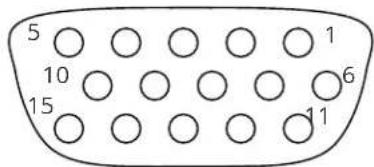
- Red / Pr / R-Y
- Green / Y
- Blue / Pb / B-Y
- ID2 (input & output linked)
- GND
- GND
- GND
- GND
- No connection
- GND
- GND on input, pulled high on output (used for auto-termination)
- SDA (input & output linked)
- H sync (or composite sync for RGBS)
- V sync
- SCL (input & output linked)
RS232 / D9 socket
- N/C
- TX (Transmit data)
- RX (Receive data)
- N/C
- GND (Signal return)
- N/C
- CTS (Clear to send)
- RTS (Request to send)
- N/C
4 Pin mini-DIN S-video connector (YC) input
- Y (Luminance)
- GND
- GND
- C (Chrominance)
Specifications
See product front and rear diagrams for details of product I/O. Not all units in the series have all the inputs and outputs listed here.
Video Inputs
Input impedance: 75 Ohm
Television standards supported: NTSC and PAL
Composite video via BNC
S-Video (YC) via 4-Pin mini-DIN Connector
CV/YC video decoder: 8-bit Digital
De-Interlacing (NTSC / PAL up-conversion only): pixel-level motion adaptive
Comb filter decoding: adaptive
Film mode (NTSC) 3:2 pull down for up-conversion
CV/YC Video adjustments: contrast, brightness, saturation, hue (NTSC)
CV/YC sub-carrier lock range: +/- 200Hz for NTSC Operation, +/- 250Hz for PAL Operation
Computer Input
Analog RGB/YPbPr via HD15 into 75 Ohm, supporting RGBHV, RGBS, RGsB, YPbPr, auto-terminating into 75 Ohm
Digital sync (in RGBHV or RGBS mode): TTL Level, 10K termination, pos or negative
Analog sync (in RGsB, YPbPr, YUV modes): 0.3v negative.
RGB Level Range: 0.5-2.0 Vp-p approx.
Scan Rate Detection: automatic
PC Resolutions: any up to 2048x2048
HDTV Resolutions: any up to 1080p
Max horizontal scan rate: 150kHz
Video Outputs (not present on all units)
Output impedance 75 Ohm
Television standards supported: NTSC and PAL
Composite Video 1v p-p via BNC
S-Video (YC) 1v p-p via 4-pin mini-DIN
CV/YC Video encoder: 8/10-bit Digital
Computer Outputs
Analog output impedance 75 Ohm
Analog RGBHV, RGBS, RGsB, YPbPr (0.7v RGB / 1.0v sync-tip to white, approx. 0.4v DC offset)
Connectors: HD-15 and/or 5 x BNC
PC Resolutions: any up to 2048x2048 (user adjustable)
HDTV Resolutions: any up to 1080p
Vertical Refresh Rate: any to 250Hz
Locking/Mixing
CV/YC SC/H phase adjustments: +/- 180 degrees (for units with CV/YC output only)
Keyer: chromakey (YUV) or lumakey (Y)
Mixer: PC / Video, foreground/background swappable
PIP: variable window size & position - single-button enabling
(Not all locking/mixing combinations are available: you cannot overlay one CV or YC source over a different CV or YC source, or one RGB/YUV source over another RGB/YUV source – you are restricted to overlaying CV/YC over RGB/YUV, or RGB/YUV over CV/YC (the exception is where you can overlay one source over itself).
Scaling / sampling / memory
Size and position: automatic via AutoSet or Manual
Image size: user-definable presets
Image freeze: one video frame
Settings memory: non-Volatile
Zoom range: variable to 10x Zoom (1000%)
Shrink range: variable to 10%
Image mirroring: Horizontal and/or Vertical
Horizontal filtering: full digital
Conversion technology: proprietary
Color resolution: 24-bit (16.8 Million Colors)
Sampling rate: 108MHz maximum
Digital sampling: 24-bit, 4:4:4 format
Firmware memory: flash, upgradeable via RS-232
Regulatory Compliance
Main unit conforms to FCC, CE, RoHS
Environmental
Operating Temperature 0° to +45° C (+32° to +113° F)
Operating Humidity 10% to 85%, Non-condensing
Storage Temperature -10° to +70° C (+14° to +158° F)
Storage Humidity 10% to 85%, Non-condensing
Power Requirement
External power supply: 12V DC @1A maximum.
Actual current consumption varies between units.
Internal over-voltage & over-current protection.
Full PSU specification: 12v DC regulated 1Amp PSU with a 2.5mm locking center-pin positive DC power connector. A non-locking 2.5mm DC power connector will also fit.
Control Methods
The unit can be controlled locally via the front panel buttons and on-screen display (OSD), remotely via the RS-232 interface (as applicable) using a D9 female connector or again remotely via the Infrared remote using the infra-red remote unit.
Accessories Included
Varies depending on unit – see earlier in manual
Mechanical
Size (H x W x D): 1.2"x7.9"x3.5" (30x200x90mm)
Weight (Net): 1.3 lbs (580g)
Contact us
□tvone.com
info@tvone.com
□Support NCSA: tech.usa@tvone.com
□Support EMEA: tech.europe@tvone.com
□Support Asia: tech.asia@tvone.com
Information in this document is subject to change without notice. No part of this publication may be reproduced, stored in a retrieval system, or transmitted in any form or any means electronic or mechanical, including photocopying and recording for any purpose other than the purchaser's personal use without the written permission of tvONE.
Copyright © 2019 tvONE™. All rights reserved.
Registered in the U.S. Patent and Trademark Office.


- Product images....2
- Front panel controls.... 3
- Video inputs and outputs....6
- Infra-red remote control 7
- Menu LAYOUT and SETTINGS Adjustment 7
- Items Associated with the Adjust keyers group 17
- Items Associated with the Adjust sources group....19
- Welcome
- 1T-C2-100 Down Converter
- 1T-C2-150 Down Converter PLUS
- 1T-C2-200 Video Scaler
- 1T-C2-250 Video Scaler PLUS
- 1T-C2-400 PC/HD Scaler
- Device Features
- General Topography
- Ultimate flexibility
- Simple Control
- Upgradeability
- Product images
- Front panel controls
- Button controls
- MENU ↓ and ↑ buttons
- Advanced menus
- Special button combinations and functions
- Locking front panel buttons & IR remote control
- Factory Reset
- Switching units between different resolutions using the front panel
- Video inputs and outputs
- Computer and Video inputs
- Computer and Video outputs
- Infra-red remote control
- Menu LAYOUT and SETTINGS Adjustment
- Items Associated with the Adjust outputs group
- Items Associated with the Adjust windows group
- Extended scaling controls
- Items Associated with the Adjust keyers group
- Items Associated with the Adjust sources group
- Menu items common to all inputs
- DVI Source Menu Items
- RGB Source Menu Items
- CV & YC Source Menu Items
- Still Image Store / Testcard Source Menu Items
- Items associated with the Adjust resolutions group
- Important Cautionary Information
- Items Associated with the System group
- Serial port
- Connection
- Communications protocol
- Serial / IP control specification
- Communication protocol basics
- Packet format
- Function list
- Examples
- Reading and writing macros
- Reading a previously stored Macro
- Writing to a macro
- Run and Restore macros
- Emulate a front panel button press
- Reset command
- Common operations
- Operation of the Keyer
- Preparation:
- Adjustment:
- Troubleshooting and technical support
- There is no picture on the Output.
- The image is shifted and not fully viewable
- The output resolutions no longer appear as expected.
- There is excessive flicker on the Output.
- The Output image is distorted.
- Some colors appear to be incorrect on the CV/YC output
- How can I reduce color smearing on CV connections?
- I can no longer adjust the Output image resolution.
- The picture on the video display is black and white.
- General troubleshooting checklist
- Returning a product for repair
- EMEA and Asia
- All customers
- Connector pinouts
- HD15 connector
- RS232 / D9 socket
- Pin mini-DIN S-video connector (YC) input
- Specifications
- Video Inputs
- Computer Input
- Video Outputs (not present on all units)
- Computer Outputs
- Locking/Mixing
- Scaling / sampling / memory
- Regulatory Compliance
- Environmental
- Power Requirement
- Control Methods
- Accessories Included
- Mechanical
- Contact us
Brand : TV One
Model : 1T-C2-150
Category : Audio/video converter