
MSA-AMK2-10 - Wall mount for screen AMX - Free user manual and instructions
Find the device manual for free MSA-AMK2-10 AMX in PDF.


| Product Type | Any Mount Kit for touch panels |
| Model Number | MSA-AMK2-10 |
| Part Number | FG2265-36 |
| Dimensions (HWD) | 6.53" x 9.76" x 0.98" (16.6cm x 24.8cm x 2.5cm) |
| Weight | 0.25 lbs (113.40 g) |
| Compatible Touch Panels | MSD-1001-L2 (10.1" Modero S Series Landscape Wall Mount Touch Panel) and RMBK-1001 (10.1" AMX RoomBook Scheduling Touch Panel) |
| Gang Box Compatibility | Standard single and double gang boxes (US, EU, UK, Australia) |
| Generation | Second-generation (AMK2) |
| Mounting Orientation | Landscape |
| Installation Method | Attach back box to gang box, latch panel onto top hooks, rotate down |
| Included Accessories | Back Box, Foam Gasket, Screws (M3.5 x 30mm, 4 pcs; #6-32 x 1.25, 4 pcs) |
| Optional Accessory | Foam gasket (included) for filling gaps |
| Power Requirement | PoE (Power over Ethernet) via touch panel |
| Connection Type | Ethernet (RJ-45) from wall to panel |
| Material | Plastic back box (typical) |
| Color | Black (typical) |
| Safety Warnings | Do not over-tighten screws; check for gaps before locking panel |
| Maintenance | Keep clean; avoid forcing panel during removal |
| Additional Documentation | Available at www.amx.com (RoomBook and Modero S Series manuals) |
Frequently Asked Questions - MSA-AMK2-10 AMX
User questions about MSA-AMK2-10 AMX
0 question about this device. Answer the ones you know or ask your own.
Ask a new question about this device
Download the instructions for your Wall mount for screen in PDF format for free! Find your manual MSA-AMK2-10 - AMX and take your electronic device back in hand. On this page are published all the documents necessary for the use of your device. MSA-AMK2-10 by AMX.
USER MANUAL MSA-AMK2-10 AMX
MSA-AMK/2 Any Mount Kits
The MSA-AMK/2-xx Any Mount Kits (FIG. 1) are designed to mount Modero S Series Wall Mount Touch Panels and AMX RoomBook Scheduling Panels (7" and 10.1") into standard sized single and double gang boxes in the US, EU, UK and Australia,

FIG. 1 MSA-AMK/2-10 AND MSA-AMK/2-07
Models Available/Panel Compatibility
There are several versions of the Any Mount Kits available to accommodate 7" and 10" Modero S Series (wall mount, landscape) and AMX RoomBook Scheduling Touch Panels:
MODELS AVAILABLE/PANEL COMPATIBILITY:
| Any Mount Kit For use with: | |
| MSA-AMK2-10 (FG2265-36) | • MSD-1001-L2 (FG2265-31): 10.1" Modero S Series Landscape Wall Mount Touch Panel• RMBK-1001 (FG2265-40): 10.1" AMX RoomBook Scheduling Touch Panel |
| MSA-AMK-10 (FG2265-26) | • MSD-1001-L (FG2265-01): 10.1" Modero S Series Landscape Wall Mount Touch Panel• RMBK-1001 (FG2265-40): 10.1" AMX RoomBook Scheduling Touch Panel |
| MSA-AMK2-07 (FG2265-35) | • MSD-701-L2 (FG2265-32): 7" Modero S Series Landscape Wall Mount Touch Panel• RMBK-701 (FG2265-37): 7" AMX RoomBook Scheduling Touch Panel |
| MSA-AMK-07 (FG2265-25) | • MSD-701-L (FG2265-01): 7" Modero S Series Landscape Wall Mount Touch Panel• RMBK-701 (FG2265-37): 7" AMX RoomBook Scheduling Touch Panel |
"AMK2" Multi Mount Kits
The MSA-AMK2-10 and MSA-AMK2-07 Multi Mount Kits are intended for use with second-generation "-L2" Modero S Series (Landscape/Wall Mount), as well as all AMX RoomBook Scheduling touch panels.
Note that the installation procedure for the second-generation AMK2 versions of the kits is essentially the same as the first-generation AMK kits, with only a minor change to the top hook design.
Product Specifications
| PRODUCT SPECIF ICATIONS | |
| Dimensions (HWD): | • MSA-AMK/2-10: 6.53" x 9.76" x 0.98" (16.6cm x 24.8cm x 2.5cm) • MSA-AMK/2-07: 4.88" x 7.38" x 0.91" (12.39cm x 18.75cm x 2.25cm) |
| Weight: • MSA-AMK/2-10: 0.25 lbs (113.40 g) • MSA-AMK/2-07: 0.10 lbs (45.36 g) | |
| Included Accessories: | MSA-AMK/2-10: • Back Box (60-2265-34) • Gasket, Foam (66-2265-30) • Screw, M3.5 X 30mm, PFH, Clear Zinc (4) (80-1620-04) • Screw, #6-32 X 1.25, PFH, Type F, Clear Zinc (4) (80-1700-09) MSA-AMK/2-07: • Back Box (60-2265-33) • Gasket, Foam (66-2265-29) • Screw, M3.5 X 30mm, PFH, Clear Zinc (4) (80-1620-04) • Screw, #6-32 X 1.25, PFH, Type F, Clear Zinc (4) (80-1700-09) |
Installation of the Any Mount Kit
The Any Mount Kits are designed to utilize existing or newly installed gang boxes, with a new back box to replace the back box included with the touch panel. To install an Any Mount Kit and its accompanying touch panel:
- Before starting the installation, ensure that Ethernet cable has been pulled to the gang box, and that all appropriate Power Over Ethernet (PoE) injectors have been connected to the cable going to the gang box.
- If the gang box already has an existing fixture or device installed in it, remove the fixture or device to expose the gang box (FIG. 2).

FIG. 2 EXISTING GANG BOX
- Pull the Ethernet cable into the gang box, making sure that the male RJ-45 connector is accessible within the gang box.
-
Match the screw connector holes on the gang box with the holes in the back box (FIG. 3).
-
The Any Mount Kit back box has multiple holes to allow for single or double gang box design, and for standard gang box designs from the US, UK, EU and Australia.
- Examine how the back box rests on the gang box - look for gaps between the back box and the wall surface.

natural_image
Close-up of hands holding a black plastic electrical socket with a blue T-shaped cutout (no text or symbols visible)FIG. 3 TESTING THE ALIGNMENT OF THE BACK BOX SCREW HOLES.
- If the gap between the wall and the back box is excessive, or if the installation of the back box exposes too much of the gang box, you may apply the optional foam gasket (MSA-AMK/2-07: 66-2265-29; MSA-AMK/2-10: 66-2265-30) to the back of the back box. Peel the adhesive backing off the gasket and carefully apply it to the back box surface (FIG. 4).

FIG. 4 APPLYING THE OPTIONAL FOAM GASKET TO THE BACK BOX.
- Once the proper mounting position of the back box is confirmed, attach the back box to the gang box, using either the screws used with the original fixture or device or with the Included screws in the Any Mount Kit (FIG. 5). WARNING: Be careful not to over-tighten the screws - this can bow or damage the back box.

natural_image
Close-up of hands installing or adjusting a black electronic device with blue components and screws (no visible text or symbols)FIG. 5 INSTALLING THE BACK BOX TO THE GANG BOX.
- After installing the back box, inspect the back box's placement. Note: If necessary, the back box can be removed and the foam gasket installed.
- Pull enough slack on the Ethernet cable through the back box to allow the cable to reach the touch panel's RJ45 connector (FIG. 6).

FIG. 6 ACCESSING THE ETHERNET CABLE THROUGH THE BACK BOX.
- Remove the touch panel's back box to access the back of the panel.
-
Insert each connector into its corresponding location along the back of the touch panel. Note: For more information on connections, please refer to the Operation Reference Guide for the Modero S Series panel being installed, available from www.amx.com.
-
Test the incoming wiring by attaching the panel connections to their terminal locations and applying power. Note: Verify that the panel is receiving power and functioning properly to prevent repetition of the installation.
-
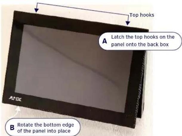
Latch the panel onto the top hooks on the back box and rotate it down (FIG. 7).
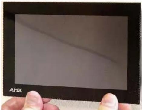
- Press gently and evenly on the surface of the touch panel until the panel locks into place (FIG. 8).
natural_image
Hand holding a black tablet with a diagonal line on the screen (no visible text or symbols)FIG. 8 LOCKING DOWN THE BOTTOM OF THE TOUCH PANEL ONTO THE BACK BOX.
WARNING: If you see a gap between the panel and the back box, or feel any binding while locking down the panel, stop immediately and verify that no cables or other items are in the way. Do not force the panel into position, as this can cause damage to the touch screen or the panel electronics.
Removing the Touch Panel
In order to access the back of the touch panel, such as to install a USB connection for firmware upgrades, the device may need to be removed from the back box. To remove the touch panel:
- From the bottom, pull gently outward from the back box. Gently rock the panel back and forth to free the bottom from the back box.
- Rotate it up to release the top latch hooks, and carefully pull the device free from the back box. Take care not to damage or pull the connections on the back of the device, or to pull the back box from the gang box.
Additional Documentation
The following related product documents are available to view/download at www.amx.com:
- For information on installing and configuring AMX RoomBook Scheduling Touch Panels, refer to the AMX RoomBook Scheduling Touch Panels Instruction Manual.
- For information on installing Modero S Series Touch Panels, refer to the Modero S Series Touch Panels Installation Hardware Reference Manual.
- Specification drawings of the MSA-AMK/2 Any Mount Kits.
Brand : AMX
Model : MSA-AMK2-10
Category : Wall mount for screen