
95-8150 - Car kit Metra - Free user manual and instructions
Find the device manual for free 95-8150 Metra in PDF.


| Product Type | Car Audio Installation Kit |
| Brand | Metra |
| Model | 95-8150 |
| Compatible Vehicles | Select vehicles (see fit guide) |
| Dimensions | 10 x 6 x 2 inches |
| Weight | 0.5 lbs |
| Material | High-grade ABS plastic |
| Color | Black |
| Power Supply | Passive (no power required) |
| Primary Function | Connect aftermarket radio to factory wiring harness |
| Secondary Function | Provide dash trim plate for flush mounting |
| Included Components | Wiring harness, dash trim, mounting brackets, screws |
| Installation Level | Intermediate (requires wiring knowledge) |
| Maintenance | Wipe with a dry cloth; avoid solvents |
| Safety Precautions | Disconnect battery before installation; ensure proper grounding |
| Spare Parts Availability | Replacement harnesses sold separately |
| Repairability | Non-repairable; replace entire kit if damaged |
| Quality Certification | Meets OEM fitment standards |
Frequently Asked Questions - 95-8150 Metra
User questions about 95-8150 Metra
0 question about this device. Answer the ones you know or ask your own.
Ask a new question about this device
Download the instructions for your Car kit in PDF format for free! Find your manual 95-8150 - Metra and take your electronic device back in hand. On this page are published all the documents necessary for the use of your device. 95-8150 by Metra.
USER MANUAL 95-8150 Metra
INSTALLATION INSTRUCTIONS FOR PART 95-8150
APPLICATIONS
LEXUS ES SERIES
1992-1996
95-8150
KIT FEATURES
• Double DIN Radio Provision
- Stacked ISO Mount Units Provision

natural_image
Interior view of a car dashboard with air filters and control panel (no visible text or symbols)KIT COMPONENTS
A) Double Din Trim Plate
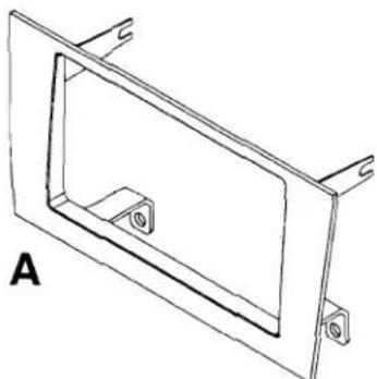
natural_image
Technical line drawing of a rectangular frame with mounting holes and a central recessed cutout (no text or symbols)TOOLS REQUIRED:
Small Flat Blade Screwdriver/ Panel Removal Tool
• Phillips Screwdriver • Socket Set

natural_image
Line drawings of four different types of screwdrivers (no text or symbols)
1-800-221-0932

www.metraonline.com
© COPYRIGHT 2004-2007 METRA ELECTRONICS CORPORATION
TABLE OF CONTENTS
Dash Disassembly
- Lexus ES Series 1992-1996 ....1
Kit Assembly
- Double DIN Radio Provision ....2
- Stacked ISO Mount Units Provision 2
Final Assembly 3
*Note:
Refer also to the instructions included with the aftermarket radio.
LEXUS ES SERIES 1992-1996
1 Disconnect the negative battery terminal to prevent an accidental short circuit.
2 Unclip and remove the plastic trim piece below the factory radio and remove (2) Phillips screws exposed underneath. (Figure A)
3 Using a small flat blade screwdriver release the clips securing the a/c vent assembly and remove the assembly. (Figure B)
4 Remove (2) Phillips screws inside of vent cavity. (Figure B)
5 Pull the climate control/radio assembly from the dash and disconnect the wiring. (Figure C)
6 Remove (2) Phillips screws and (4) bolts per side to remove factory brackets from climate controls and radio.(Retain the factory brackets, climate controls and screws to be re-installed during kit assembly).
Continue to kit assembly.


natural_image
Diagram of a car interior showing air vent, mode shift, and control panel (no text or labels)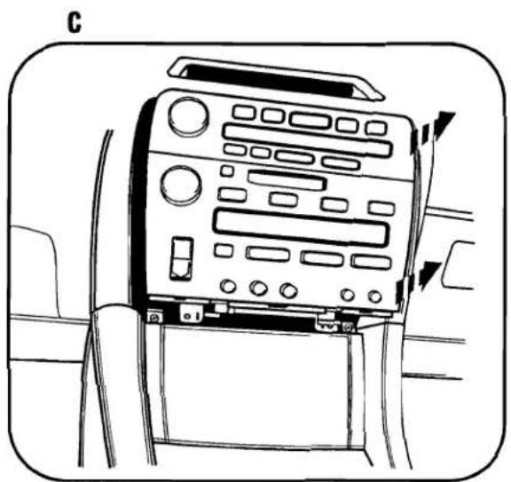
natural_image
Interior view of a car dashboard with control panel and side-mounted buttons (no text or symbols visible)LEXUS ES SERIES 1992-1996
DOUBLE DIN RADIO
STACKED ISO MOUNT UNITS PROVISION
Note: Refer also to the instructions included with the aftermarket radio.
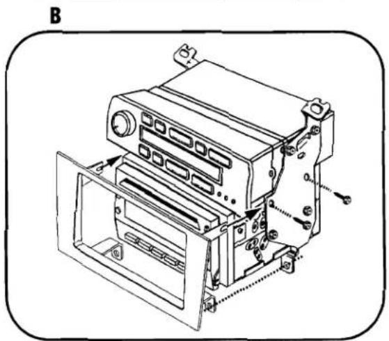
1 Assemble the climate controls and Double DIN or stacked ISO mount units into the factory brackets using the hardware from disassembly and the screws supplied with the Double DIN or stacked ISO mount units. (Figure A)
2 Before tightening the top (2) mounting screws to the Double DIN or stacked ISO mount units attach the Double DIN trim plate and secure with the top (2) mounting screws. (Figure B)
Continue to final assembly.

natural_image
Technical line drawing of an internal device housing with mounting brackets and mounting holes (no text or symbols)FINAL ASSEMBLY

(A) Strip wire ends back 1/2"
B) Twist ends together
C) Solder
D) Tape
1 Locate the factory wiring harness in the dash. Metra recommends using the proper mating adapter and making connections as shown. (Isolate and individually tape off the ends of any unused wires to prevent electrical short circuit.)
2 Re-connect the negative battery terminal and test the unit for proper operation.
3 Reassemble radio and dash assemblies in reverse order of disassembly.
FINAL WIRING CONNECTIONS
Make wiring connections using the EIA color code chart shown below and the instructions included with the head unit. Metra recommends making connections as shown below; Strip, Splice, Solder, Tape. Isolate and individually tape off ends of any unused wires to prevent electrical short circuit.
METRA / EIA WIRING CODE
| 12V Ignition / Acc. . . . . . . . . . . . . . . . . . . . . . . . . . . . . . . . . . . . . . . . . . . . . . . . . . . . . . . . . . . . . . . . . . . . . . . . . . . . . . . . . . . . . . . . . . . . . . . . . . . . . | Right Front (+) . . . . . . . . . . . . . . . . . . . . . . . . . . . . . . . . . . . . . . . . . . . . . . . . . . . . . . . . . . . . . . . . . . . . . . . . . . . . . . . . . . . . . . . . . . . . . . . . . . . |
| 12V Batt / Memory. . . . . . . . . . . . . . . . . . . . . . . . . . . . . . . . . . . . . . . . . . . . . . . . . . . . . . . . . . . . . . . . . . . . . . . . . . . . . . . . . . . . . . . . . . . . . . . . . . . | Left Front (+) . . . . . . . . . . . . . . . . . . . . . . . . . . . . . . . . . . . . . . . . . . . . . . . . . . . . . . . . . . . . . . . . . . . . . . . . . . . . . . . . . . . . . . . . . . . . . . . . |
| Ground. . . . . . . . . . . . . . . . . . . . . . . . . . . . . . . . . . . . . . . . . . . . . . . . . . . . . . . . . . . . . . . . . . . . . . . . . . . . . . . . . . . . . . . . . . . . . . . . . . . Power Antenna. . . . . . . . . . . . . . . . . . . . . . . . . . . . . . . . . . . . . . . . . . . . . . . Amp Turn-On. . . . . . . . . . . . . . . . . . Blue / White Amp Ground. . . . . . . . . . . . . . . . . Black / White Illumination. . . . . . . . . . . . Orange Dimmer. . . . . . . . . . . . . . Orange / White | Right Front (-). . . . . . . . . . . . . . . . . . . . . . . Gray/ Black Gray/ Black White Left Front (-). White / Black Right Rear (+) . Violet Right Rear (-) . Violet / Black Left Rear (+) . Green Left Rear (-) . Green / Black |
*NOTE: When a Black wire is not present, ground radio to vehicle chassis. All colors may not be present on all leads due to manufacturer's specifications.
NOTES
NOTES
95-8150 INSTRUCTIONS
Brand : Metra
Model : 95-8150
Category : Car kit