
TM-582 - Computer Case ASUS - Free user manual and instructions
Find the device manual for free TM-582 ASUS in PDF.


| Product Type | Computer Case |
| Brand | ASUS |
| Model | TM-582 |
| Form Factor | Mid-Tower |
| Motherboard Compatibility | ATX, Micro-ATX, Mini-ITX |
| Expansion Slots | 7 |
| Internal 3.5" Drive Bays | 2 |
| Internal 2.5" Drive Bays | 2 (or convertible from 3.5") |
| Front I/O Ports | USB 3.0 x2, USB 2.0 x2, Audio In/Out |
| Cooling Support (Front) | 2 x 120mm or 2 x 140mm fans (optional) |
| Cooling Support (Rear) | 1 x 120mm fan (pre-installed) |
| Cooling Support (Top) | 2 x 120mm fans (optional) |
| Maximum GPU Length | 330 mm (without front fan) |
| Maximum CPU Cooler Height | 155 mm |
| Power Supply Mounting | Bottom, ATX |
| Material | Steel, Plastic front panel |
| Side Panel | Acrylic window |
| Dimensions (W x H x D) | 200 x 450 x 430 mm |
| Weight | ~4.5 kg |
| Dust Filters | Front and bottom (removable) |
| Cable Management | Space behind motherboard tray |
| Tool-less Design | Drive bays, expansion slots |
| Included Fans | 1 x 120mm rear fan |
| Warranty | 1 year limited |
Frequently Asked Questions - TM-582 ASUS
User questions about TM-582 ASUS
0 question about this device. Answer the ones you know or ask your own.
Ask a new question about this device
Download the instructions for your Computer Case in PDF format for free! Find your manual TM-582 - ASUS and take your electronic device back in hand. On this page are published all the documents necessary for the use of your device. TM-582 by ASUS.
USER MANUAL TM-582 ASUS
natural_image
Exterior view of a desktop computer tower with black and silver casing, no visible text or symbolsScrewless ModelScrewless Model
Copyright © 2005 ASUSTeK COMPUTER INC. All Rights Reserved.
Removing the side cover and front bezelRemoving the side cover and front bezel
natural_image
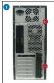
Back view of a desktop computer tower showing ventilation fans and drive bays (no text or labels visible)Remove the screws on the rear panel.

natural_image
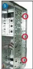
Front view of a black server rack with ventilation fans and a circular vent, showing internal components (no text or symbols visible)Push the side cover towards the rear panel.
Release the side tabs that secure the front bezel to the chassis.

natural_image
Interior view of a computer tower case showing drive bays and ventilation slots (no text or labels visible)Swing the front bezel in the direction of the arrow.
Unhook the hinge-like tabs. Set the front bezel aside.
Installing the power supply unit (PSU)Installing the postallingsphy optic PSUsk drive (ODD)Installing an optstallingkadrard (ODD)drive (HDD)Installing a hard disl

Locate the PSU slot.
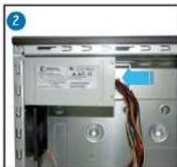
Slide the PSU into the slot until it snugly fits the metal rail.

Push the bay lock upward.

Insert the ODD into the bay.


1. Push the bay lock upward.
2. Insert the HDD into the bay.
3. Align the HDD holes with the bay holes, then push down the bay lock to secure the HDD.
Secure with screws.

Align the ODD holes with the bay holes, then push down the bay lock to secure the ODD.
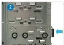
Release the lock tabs on the front bezel to disengage the drive cover.
Installing a floppy disk drive (FDD)Installing a floppy install driver(FDP)ansion cardInstalling an expansion Reinstalling the side cover and front bezelReinstalling

Using a screwdriver, push the knock-down metal cover in and out of the chassis until it is removed.
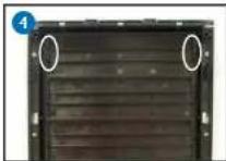
Insert the FDD into the bay. Make sure the FDD holes align with the chassis holes.

Choose the slot that you want to use. Push to unlock the lock tab. Remove the metal cover opposite the slot that you want to use.

Align the card connector with the slot, then press firmly until the card is completely seated on the slot.
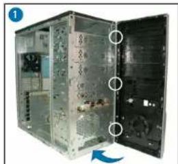
Hook the hinge-like tabs to the holes on the chassis. Swing the front bezel in the direction of the arrow and push to secure the front bezel to the chassis.
natural_image
Interior view of a server room with open door and internal equipment (no visible text or symbols)
natural_image
Interior view of a server rack unit with open door and visible internal components (no text or symbols)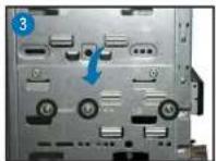
Secure the FDD with screws.

Release the lock tabs on the front bezel to disengage the drive cover.

Photo shows the card seated on the slot.

Push the expansion card lock on the rear panel to secure the slot.

natural_image
Exterior view of a black server rack with a circular vent and arrow indicating direction (no text or symbols)Push the side cover towards the front bezel.
natural_image
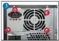
Back view of a desktop computer tower showing ventilation duct, drive bays, and tower panel (no text or labels visible)Drive screws on the rear panel.

natural_image
Exterior view of a black desktop computer tower with ventilation slots and a blue cushion (no visible text or symbols)Standard Model Standard Model
Removing the side covers and front bezelRemoving the side covers and front bezel

natural_image
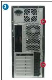
Back view of a computer tower with ventilation fans and drive bays (no visible text or labels)Remove the screws on the rear panel.
natural_image
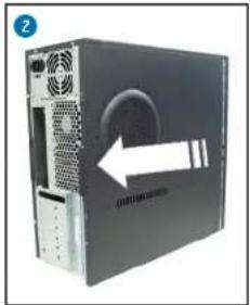
Front view of a server rack with ventilation grilles and a highlighted drive (no text or symbols visible)Push the side cover towards the rear panel.
Repeat steps 1 and 2 to remove the other side cover

Release the side tabs that secure the front bezel to the chassis.
natural_image
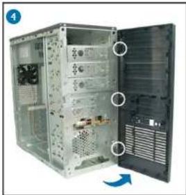
Interior view of a computer tower case showing internal components and ventilation ducts (no text or labels visible)Swing the front bezel in the direction of the arrow.
Unhook the hinge-like tabs. Set the front bezel aside.
Installing the power supply unit (PSU)Installing the postallingsupply optic PSUsk drive (ODD)Installing an optstallingkadrave (ODD)drive (HDD)Installing a hard disl

Locate the PSU slot.

Slide the PSU into the slot until it snugly fits the metal rail.
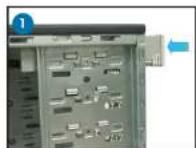
Insert the ODD into the bay.

Align the ODD holes with the bay holes, then secure the ODD with screws on both sides of the bay.


Secure with screws.

Release the lock tabs on the front bezel to disengage the drive cover.
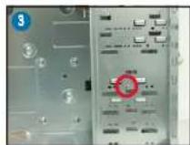
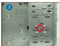
1. Insert the HDD into the bay.
2. Align the HDD hole with the bay hole.
3. Secure the HDD with a screw on both sides of the bay.
Installing a floppy disk drive (FDD)Installing a floppy installing over (FD) expansion cardInstalling an expansion cardInstalling the side cover and front bezelReinstallir

Using a screwdriver, push the knock-down metal cover in and out of the chassis until it is removed.

Insert the FDD into the bay. Make sure the FDD holes align with the chassis holes.

Remove the screws securing the bracket to the chassis. Remove the expansion slot bracket.

Choose the slot you want to use. Remove the metal cover on the rear panel.
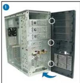
Hook the hinge-like tabs to the holes on the chassis. Swing the front bezel in the direction of the arrow and push to secure the front bezel to the chassis.
natural_image
Interior view of a computer tower case showing open door, fan, and ventilation slots (no text or symbols visible)
Secure the FDD with screws.

Release the lock tabs on the front bezel to disengage the drive cover.

Lay the chassis on a flat, stable surface. Align the card connector with the slot, then press firmly until the card is completely seated on the slot.

Replace the expansion slot bracket and secure it with the screws you removed earlier.
natural_image
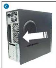
Front view of a black desktop computer tower with ventilation grilles and a circular vent (no visible text or labels)Push the side cover towards the front bezel.

natural_image
Back view of a desktop computer tower showing ventilation slots and drive bays (no visible text or labels)Drive screws on the rear panel.
Brand : ASUS
Model : TM-582
Category : Computer Case