
PWA-14S - Projector accessory Peerless-AV - Free user manual and instructions
Find the device manual for free PWA-14S Peerless-AV in PDF.


| Product Type | Projector Wall Mount Support Arm |
| Brand | Peerless-AV |
| Model | PWA-14S |
| Maximum Load Capacity | 50 lb (22.7 kg) |
| Compatible Mounts | PJF2-1 and PRS series |
| Supported Wall Types | Wood stud, solid concrete, cinder block, metal stud |
| Installation Type | Wall-mounted |
| Hardware Included | Support arm, carriage bolt, M10 locknut, M10 steel washer, M10 bronze washer, #14 x 2.5" wood screws (2), threaded rod adapter, end cap |
| Recommended Tools | Drill, hammer, socket wrench, pencil, stud finder |
| Wood Screw Torque Limit | 80 in·lb (9 N·m) maximum |
| Safety Factor | Wall must support 4 times total load |
| Required Anchor Kits (not included) | ACC200 or ACC203 for concrete; ACC415 for metal stud |
| Threaded Rod Adapter Thread | M10 |
| Material | Steel |
| Cleaning | Wipe with a dry cloth. Do not use abrasive cleaners. |
| Maintenance | Periodically check and tighten all fasteners. |
| Customer Service | 1-800-865-2112 (North America) |
| Replacement Parts | Available through Peerless customer service |
| Repair | Contact Peerless customer care for repair options |
Frequently Asked Questions - PWA-14S Peerless-AV
User questions about PWA-14S Peerless-AV
0 question about this device. Answer the ones you know or ask your own.
Ask a new question about this device
Download the instructions for your Projector accessory in PDF format for free! Find your manual PWA-14S - Peerless-AV and take your electronic device back in hand. On this page are published all the documents necessary for the use of your device. PWA-14S by Peerless-AV.
USER MANUAL PWA-14S Peerless-AV
Installation and Assembly - Vector Pro ^™ and PRS Projector Wall Mounts
Models: PWA-14, PWA-14S, PWA-14W
IMPORTANT! Read entire instruction sheet before you start installation and assembly.
IMPORTANT! Certain types of walls require additional mounting hardware...
WARNING
- This product was designed and intended to be mounted to the following supporting surfaces checked below with the hardware included in this product as specified in the installation sheet. To mount this product to an alternative supporting surface, contact Peerless customer care at 1 800 865-2112.
- This product was designed to be installed on the following wall construction only;
WALL CONSTRUCTION
Wood Stud None
xWood Beam None
☐ Solid Concrete Do not attach except with Peerless accessory kit for solid concrete; Contact Customer Service for Peerless accessory kit for solid concrete.
☐ Cinder Block Do not attach except with Peerless accessory kit for cinder block; Contact Customer Service for Peerless accessory kit for cinder block.
☐ Metal Stud Do not attach except with Peerless accessory kit for metal studs;
Contact Customer Service for Peerless accessory kit for metal studs.
□ Brick Contact Customer Service
☐ Other or unsure? Contact Customer Service

natural_image
Technical line drawing of a mechanical arm or robotic device mounted on a base (no text or symbols visible)Max. Load Capacity
50 lb (22.7 kg)
Some of the following tools may be required:
Drill, hammer, socket wrench, pencil, stud finder
TURN TO THE APPROPRIATE PAGE FOR YOUR INSTALLATION.
Installations:
To Wood Stud Walls...... step 2, page 3
To Concrete Walls......step 3, page 4
To Metal Stud Walls......step 4, page 5
| Parts List | ||||
| Model # PWA-14 PWA-14S PWA-14W | ||||
| Description | Qty. | Part # | Part # | Part # |
| A support arm | 1 | 017-1019 | 017-4019 | 017-2019 |
| B carriage bolt | 1 | 580-1022 | 580-2022 | 580-2022 |
| C M10 locknut | 1 | 530-9402 | 530-9404 | 530-9404 |
| D M10 steel washer | 1 | 540-9407 | 540-9470 | 540-9470 |
| E M10 bronze washer | 1 | 540-9441 | 540-9441 | 540-9441 |
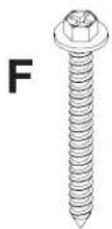
| F #14 x 2.5 phillips wood screw | 2 | 5S1-015-C03 | 5S1-015-C04 | 5S1-015-C04 |
| G threaded rod adapter | 1 | 580-1021 | 580-2021 | 580-2021 |
| H end cap | 1 | 590-1014 | 590-4014 | 590-1001 |
| Some parts may appear slightly different than illustrated. | ||||

Attach threaded rod adapter (G) to support arm (A) using carriage bolt (B), locknut (C), steel washer (D) and bronze washer (E) as shown. Insert end cap (H) into end of support arm (A) as shown.

Installation to a wood stud wall

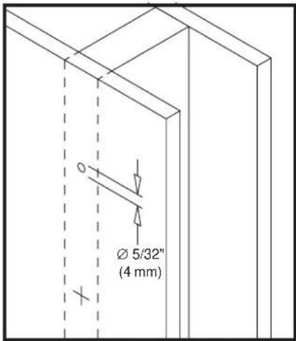
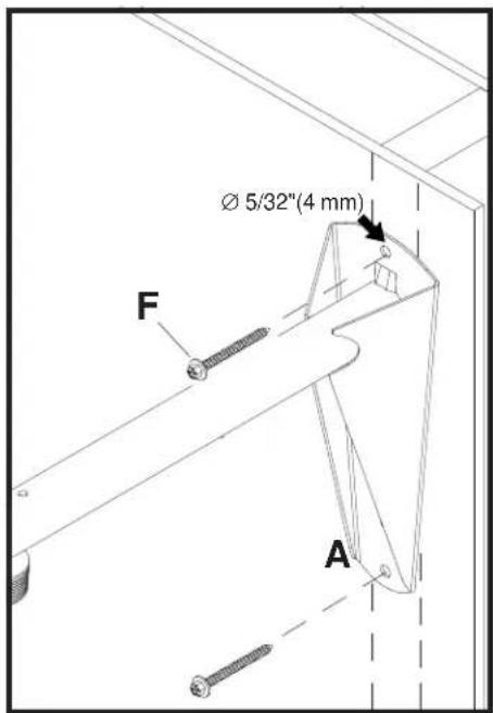
Drill two 5/32" (4 mm) dia. holes 2 1/2" (65 mm) deep. Attach wall arm (A) with #14 x 2.5"(6 mm x 65 mm) wood screws (F).
WARNING
- Tighten wood screws so that wall plate is firmly attached, but do not overtighten. Overtightening can damage the screws, greatly reducing their holding power.
- Never tighten in excess of 80 in · lb (9 N.M.).
- Make sure that mounting screws are anchored into the center of the studs. The use of an "edge to edge" stud finder is highly recommended.

natural_image
Technical line drawing of a door panel and a door assembly with a clip, showing directional arrows and labeled section A (no text or symbols beyond labels)
WARNING
- When installing Peerless wall mounts on cinder block, verify that you have a minimum of 1-3/8" of actual concrete surface in the hole to be used for the concrete anchors. Do not drill into mortar joints! Be sure to mount in a solid part of the block, generally 1" minimum from the side of the block. Cinder block must meet ASTM C-90 specifications. It is suggested that a standard electric drill on slow setting is used to drill the hole instead of a hammer drill to avoid breaking out the back of the hole when entering a void or cavity.
- Concrete must be 2000 psi density minimum. Lighter density concrete may not hold concrete anchor.
- Make sure that the wall will safely support four times the combined load of the equipment and all attached hardware and components.

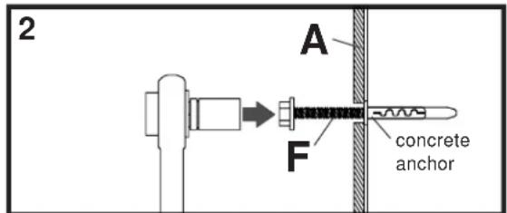
Drill two 1/4" (6 mm) dia. holes to a minimum depth of 2.5" (64 mm). Attach support arm (A) using concrete anchors(call customer service to order accessory kit ACC 200 or ACC203) and #14 x 2.5" wood screws (F) as shown in Illustration A and 1, 2, and 3. Tighten all fasteners.
WARNING
- Tighten wood screws firmly, but do not overtighten. Overtightening can damage the screws, greatly reducing their holding power.
- Never tighten in excess of 80 in • Ib (9 N.M.).

Illustration A
WARNING
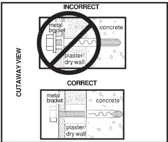
- Concrete anchors are not intended for attachment to concrete wall covered with a layer of plaster, drywall, or other finishing material. If mounting to concrete wall covered with plaster/drywall is unavoidable, plaster/drywall (up to 5/8" thick) must be counterbored as shown right. If plaster/drywall is thicker than 5/8", custom fasteners must be supplied by installer.

Drill hole and insert anchor
Place wall plate over anchor and secure with screw

After repeating step one tighten all fasteners
Installation to a metal stud wall
WARNING
- Product must be mounted through drywall that has a minimum thickness of 1/2" and into metal studs, 26 gauge or heavier.

Drill 1/2" (13 mm) dia. holes through drywall and stud. Insert togglers (call customer service to order accessory kit ACC 415) as follows.
Important: Product must be mounted through drywall that has a minimum thickness of 1/2" and into metal studs, 26 gauge or heavier.

natural_image
Technical line drawing of a mechanical clamp or spring assembly with a side view showing internal components (no text or symbols)Pivot end of toggler.

natural_image
Diagram of a cable or wire being inserted into a wall, showing rope routing and directional arrow (no text or symbols)Push into hole.

natural_image
Technical diagram of a mechanical assembly with a looped component and vertical supports (no text or symbols)Slide plastic cap forward while pulling back firmly on ring.

natural_image
Pure technical diagram of a mechanical component with no text or symbolsSnap off as shown.


Attach wall arm with 1/4-20 phillips screws.

Thread projector mount onto threaded rod adapter (G) as shown. Note: Make sure the notch in threaded rod adapter (G) is aligned with one of the four holes at the top of the PJF2-1.
Note: Installation of PRS-1 not shown. Please refer to PRS model instructions to attach PRS mount to PWA-14.

Secure PJF2-1 to threaded rod adapter (G) with one #10-32 x 3/8 socket pin screw provided with PJF2-1
Note: Installation PRS-1 not shown. Please refer to PRS model instructions to attach PRS mount to PWA-14.


Refer to PJF2-1 or PRS-1 model instructions for attachment of projector.

Brand : Peerless-AV
Model : PWA-14S
Category : Projector accessory