
ICA-SP SSWL01 - Speaker stand Techly - Free user manual and instructions
Find the device manual for free ICA-SP SSWL01 Techly in PDF.


| Product Type | Speaker Wall Mount / Stand |
| Brand | Techly |
| Model | ICA-SP SSWL01 |
| Compatible Speakers | Sonos PLAY:1 (as per manual) |
| Mounting Type | Wall Mount (brick, concrete, or wood stud) |
| Material | Steel |
| Color | Black (typical) |
| Dimensions | Approx. 150 x 150 x 100 mm (estimated) |
| Net Weight | Approx. 0.8 kg (estimated) |
| Maximum Load Capacity | 5 kg (typical for small speakers) |
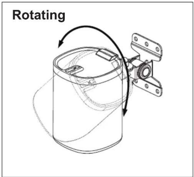
| Adjustment Features | Tilt, swivel, and rotate |
| Included Hardware | Speaker bracket, M6x10 bolt, M6x45mm lag bolts, M8x40mm concrete anchors, washers, wrench |
| Required Tools | 3.8mm drill bit, 8mm masonry bit, Phillips screwdriver |
| Installation Surface | Vertical wall (brick, concrete, or wood stud) |
| Safety Features | Secure attachment required; use provided hardware; consult professional if unsure |
| Maintenance | Periodically check tightness of screws and brackets |
| Repairability | Spare parts available from manufacturer; replaceable hardware |
| Certifications | Complies with safety standards (implied) |
| Warranty | Standard manufacturer warranty (contact Techly) |
Frequently Asked Questions - ICA-SP SSWL01 Techly
User questions about ICA-SP SSWL01 Techly
0 question about this device. Answer the ones you know or ask your own.
Ask a new question about this device
Download the instructions for your Speaker stand in PDF format for free! Find your manual ICA-SP SSWL01 - Techly and take your electronic device back in hand. On this page are published all the documents necessary for the use of your device. ICA-SP SSWL01 by Techly.
USER MANUAL ICA-SP SSWL01 Techly
Installation Instruction

natural_image
Technical line drawing of a mechanical assembly with mounting brackets and housing (no text or symbols)UNPACKING INSTRUCTIONS
- Carefully open the carton, remove contents and lay out on cardboard or other protective surface to avoid damage.
- Check package contents against the Supplied Parts List in the next page to assure that all components were received undamaged. Do not use damaged or defective parts.
- Carefully read all instructions before attempting installation.
IMPORTANT SAFETY INFORMATION
Install and operate this device with care. Please read this instruction before beginning the installation, and carefully follow all instructions contained herein. Use proper safety equipment during installation.
Please call a qualified installation contractor for help if you:
- If you don't understand these directions or have any doubts about the safety of the installation.
- If you are uncertain about the nature of your wall, consult a qualified installation contractor.
Do not use this product for any purpose or in any configuration not explicitly specified in this instruction. We hereby disclaim any and all liability for injury or damage arising from incorrect assembly, incorrect mounting, or incorrect use of this product.

WARNING
CAUTION!
This Speaker Bracket must be securely attached to the vertical wall. If the mount is not properly installed it may fall, resulting in possible injury and/or damage.
Tools Required
■ 3.8mm Drill Bit
■ 8mm Masonry Bit
■ Phillips Screwdriver
Note: The mounting components and hardware supplied in this package are not designed for installations to walls with steel studs or to cinder block walls. If the hardware you need for your installation is not included, please consult your local hardware store for proper mounting hardware for the application.
Supplied Parts List
natural_image
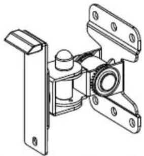
Technical line drawing of a mechanical assembly with no visible text or symbols(1)Speaker Bracket-a

(1)M6X10
Speaker Bolt-b

(4)M6x45mm
Lag Bolt-c
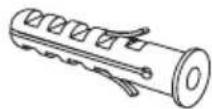
(4)M8x40mm Concrete Anchor-d

(4)Lag Bolt Washer-e

(1) Wrench-f
Step 1 Mounting the Speaker Bracket to the Wall
Brick or Concrete Wall
1.1 1.2
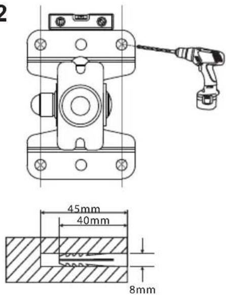

Step 1
Mounting the Speaker Bracket to the Wall
Wood Studs Wall
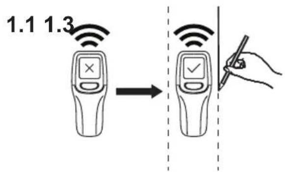
1.2

natural_image
Technical line drawing of a mechanical clamp or bracket assembly with a drill bit (no text or symbols)

Step 2
Install the SONOS PLAY 1 to the Speaker Bracket

natural_image
Technical line drawing of a mechanical assembly with labeled component 'b' (no text or symbols beyond label)Step 3 Tilting, Swing and Rotating the SONOS PLAY 1


- Installation Instruction
- UNPACKING INSTRUCTIONS
- IMPORTANT SAFETY INFORMATION
- CAUTION!
- Supplied Parts List
- Step 1 Mounting the Speaker Bracket to the Wall
- Step 1
- Mounting the Speaker Bracket to the Wall
- Step 2
- Install the SONOS PLAY 1 to the Speaker Bracket
- Step 3 Tilting, Swing and Rotating the SONOS PLAY 1
Brand : Techly
Model : ICA-SP SSWL01
Category : Speaker stand