
3500 Chassis Cab (2015) - Car RAM - Free user manual and instructions
Find the device manual for free 3500 Chassis Cab (2015) RAM in PDF.


| Product Type | Heavy-Duty Pickup Truck |
| Brand | RAM |
| Model | 3500 Chassis Cab (2015) |
| Engine | 6.7L Cummins Turbodiesel I6 |
| Horsepower | 350 hp @ 2800 rpm |
| Torque | 660 lb-ft @ 1400 rpm |
| Transmission | 6-Speed Automatic (68RFE) or 6-Speed Manual (G56) |
| Drivetrain | Rear-Wheel Drive or 4WD (selectable) |
| Gross Vehicle Weight Rating (GVWR) | 12,200 lb (Class 4) |
| Maximum Towing Capacity | Up to 30,000 lb (with gooseneck) |
| Payload Capacity | Up to 6,790 lb |
| Fuel Capacity | 52 gallons (standard tank) |
| Dimensions (L x W x H) | 237.5 in x 79.1 in x 77.5 in |
| Wheelbase | 160.5 in |
| Curb Weight | Approximately 6,500 lb (cab & chassis only) |
| Maintenance – Oil Type | SAE 15W-40 (CJ-4 or CK-4 rated) |
| Maintenance – Oil Capacity | 12 quarts (with filter) |
| Safety – Airbags | Dual front, side curtain for cab |
| Safety – ABS | 4-wheel ABS standard |
| Spare Parts – Common Replacements | Brake pads, air filter, fuel filter, belts |
| Reparability | Moderate – many parts available aftermarket |
| General Information – Manual Language | English (EN) |
| General Information – Pages | 599 |
Frequently Asked Questions - 3500 Chassis Cab (2015) RAM
User questions about 3500 Chassis Cab (2015) RAM
0 question about this device. Answer the ones you know or ask your own.
Ask a new question about this device
Download the instructions for your Car in PDF format for free! Find your manual 3500 Chassis Cab (2015) - RAM and take your electronic device back in hand. On this page are published all the documents necessary for the use of your device. 3500 Chassis Cab (2015) by RAM.
USER MANUAL 3500 Chassis Cab (2015) RAM
2015
CHASSIS CAB
OWNER'SMANUAL
VEHICLES SOLDIN CANADA
WithrespecttoanyVehiclesSoldinCanada,thename ChryslerGroupLLCshallbedeemedtobedeletedandthe nameChryslerCanadaInc.usedinsubstitutiontherefore.
DRIVINGANDALCOHOL
Drunkendrivingisoneofthemostfrequentcausesof accidents.
Yourdrivingabilitycanbeseriouslyimpairedwithblood alcohollevelsfarbelowthelegalminimum.Ifyouare drinking,don'tdrive.Ridewithadesignatednon-drinkingdriver,callacab,afriend,orusepublictransportation.
WARNING!
Drivingafterdrinkingcanleadtoanaccident. Yourperceptionsarelesssharp,yourreflexesare slower,andyourjudgmentisimpairedwhenyou havebeendrinking.Neverdrinkandthendrive.
Thismanualillustratesanddescribestheoperationof featuresandequipmentthatareeitherstandardorop-tionalonthisvehicle. Thismanualmayalsoincludea descriptionoffeaturesandequipmentthatarenolonger availableorwerenotorderedonthisvehicle.Please disregardanyfeaturesandequipmentdescribedinthis manualthatarenotonthisvehicle.
ChryslerGroupLLCreservestherighttomakechanges indesignandspecifications,and/ormakeadditionstoor improvements to its products without imposing any obligationuponitselftoinstallthemonproductspreviouslymanufactured.
Copyright©2014ChryslerGroupLLC

SECTION PAGE
TABLE OF CONTENTS
1 INTRODUCTION....3
2 THINGSTOKNOWBEFORESTARTINGYOURVEHICLE....9
3 UNDERSTANDINGTHEFEATURESOFYOURVEHICLE.... 1 1 3
4 UNDERSTANDINGYOURINSTRUMENTPANEL....195
5 STARTING AND OPERATING ....
6 WHAT TODOINEMERGENCIES....
7 MAINTAINING YOUR VEHICLE....
8 MAINTENANCESCHEDULES. 5 5 9
9 IFYOUNEEDCONSUMERASSISTANCE. 567
10 INDEX 5
INTRODUCTION
CONTENTS
■INTRODUCTION....4
■HOW TO USE THIS MANUAL....4
■WARNINGS AND CAUTIONS....6
■VAN CONVERSIONS/CAMPERS....6
■VEHICLE IDENTIFICATION NUMBER....6
■VEHICLE MODIFICATIONS/ALTERATIONS....7
4 INTRODUCTION
INTRODUCTION
Congratulations on selecting your new Chrysler Group LLC vehicle. Be assured that it represents precision workmanship, distinctive styling, and high quality - all essentials that are traditional to our vehicles.
This Owner's Manual has been prepared with the assistance of service and engineering specialists to acquaint you with the operation and maintenance of your vehicle. It is supplemented by Warranty Information, and various customer-oriented documents. Please take the time to read these publications carefully. Following the instructions and recommendations in this manual will help assure safe and enjoyable operation of your vehicle.
NOTE: After reviewing the owner information, it should bestored in the vehicle for convenient referencing and remain with the vehicle when sold.
When it comes to service, remember that your authorized dealer knows your vehicle best, has factory-trained technicians and genuine parts, and cares about your satisfaction.
HOW TO USE THIS MANUAL
Consult the Table of Contents to determine which section contains the information you desire.
Since the specification of your vehicle depends on the items of equipment ordered, certain descriptions and illustrations may differ from your vehicle's equipment.
The detailed index at the back of this Owner's Manual contains a complete listing of all subjects.
Consult the following table for a description of the symbols that may be used on your vehicle or throughout this Owner's Manual:

010533317
6 INTRODUCTION
WARNINGS AND CAUTIONS
This Owners Manual contains WARNINGS against operating procedures that could result in a collision or bodily injury. It also contains CAUTIONS against procedures that could result in damage to your vehicle. If you do not read this entire Owners Manual, you may miss important information. Observe all Warnings and Cautions.
VAN CONVERSIONS/CAMPERS
The New Vehicle Limited Warranty does not apply to body modifications or special equipment installed by van conversion/camper manufacturers/body builders. Refer to the Warranty Information book, Section 2.1.C. Such equipment includes video monitors, VCRs, heaters, stoves, refrigerators, etc. For warranty coverage and service on these items, contact the applicable manufacturer.
Operating instructions for the special equipment installed by the conversion/camper manufacturer should also be supplied with your vehicle. If these instructions are missing, please contact your authorized dealer for assistance in obtaining replacement documents from the applicable manufacturer.
For information on the Body Builders Guide refer to: www.rambodybuilder.com. This website contains dimensional and technical specifications for your vehicle. It is intended for Second Stage Manufacturer's technical support. For service issues, contact your authorized dealer.
VEHICLE IDENTIFICATION NUMBER
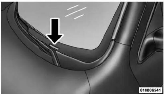
The Vehicle Identification Number (VIN) is found on the left front corner of the instrument panel, visible through the windshield. This number also appears on the vehicle
frame and underbody as well as the Automobile Information Disclosure Label affixed to a window on your vehicle, the vehicle registration and title.
natural_image
Close-up of a car's side profile showing a curved seat and dashboard, with a black arrow pointing to a detail (no text or symbols)VehicleIdentificationNumber
NOTE: It is illegal to remove or alter the VIN.
VEHICLE MODIFICATIONS/ALTERATIONS
WARNING!
Anymodificationsoralterationstothisvehiclecould seriouslyaffectitsroadworthinessandsafetyand mayleadtoacollisionresultinginseriousinjuryor death.
THINGS TO KNOW BEFORE STARTING YOUR VEHICLE
CONTENTS
■A WORD ABOUT YOUR KEYS....1 1
□Wireless Ignition Node (WIN). . . . . . . . . . . . . . 1 1
☐Keyless Ignition Node (KIN) — If Equipped . . .12
□Key Fob....
□Removing Key Fob From Ignition . . . . . . . . . 1 5
□Key-In-Ignition Reminder....17
■SENTRY KEY®....17
□Replacement Keys....18
□Customer Key Programming....19
□General Information....19
■VEHICLE SECURITY ALARM....20
□Rearming Of The System....20
□To Arm The System....20
3 □To Disarm The System ..... 2 1
□Security System Manual Override....2 2
■ILLUMINATED APPROACH....22
■REMOTE KEYLESS ENTRY (RKE) — IF EQUIPPED....2 3
□Remote Unlock The Doors....25
□To Lock The Doors....26
□ Using The Panic Alarm .....26
10 THINGS TO KNOW BEFORE STARTING YOUR VEHICLE
□Programming Additional Transmitters. . . . . . . 2 7
□Transmitter Battery Replacement....27
□General Information....30
■ REMOTE STARTING SYSTEM — IF EQUIPPED . .31
□How To Use Remote Start....3 1
■DOOR LOCKS....34
□Manual Door Locks....34
□Power Door Locks — If Equipped . . . . . . . . . 3 6
□Child-Protection Door Lock....38
■KEYLESS ENTER-N-GO™ 39
■WINDOWS....43
□Power Windows — If Equipped ..... 4 3
□Wind Buffeting 47
■OCCUPANT RESTRAINT SYSTEMS ..... 4 7
□Important Safety Precautions....47
□Seat Belt Systems....49
□Supplemental Restraint System (SRS)....64
□Child Restraints....75
□Transporting Pets....106
■ENGINE BREAK-IN RECOMMENDATIONS . . .106
□Diesel Engine....107
■SAFETY TIPS....108
□ Transporting Passengers....108
□Exhaust Gas .....109
□Safety Checks You Should Make Inside The Vehicle....11 0
☐Periodic Safety Checks You Should Make Outside The Vehicle....11 2
THINGS TO KNOW BEFORE STARTING YOUR VEHICLE 11
A WORD ABOUT YOUR KEYS
Your vehicle uses either a key start ignition system or keyless ignition system. The key start ignition system consists of a either a bladed key with an immobilizer chip in it, or a Key Fob with Remote Keyless Entry (RKE) transmitter and an Ignition Node Module (IGNM). The keyless ignition system consists of a Key Fob with Remote Keyless Entry (RKE) transmitter and a Keyless Ignition Node (KIN).
Wireless Ignition Node (WIN)
The Wireless Ignition Node (WIN) operates similar to an ignition switch. It has four operating positions, three with detents and one that is spring-loaded. The detent positions are OFF, ACC, and ON/RUN. The START position is a spring-loaded momentary contact position. When released from the START position, the switch automatically returns to the ON/RUN position.

WirelessIgnitionNode(WIN)
1—OFF
2 — ACCESSORY (ACCESSORY)
3—ON/RUN
4 — START
12 THINGS TO KNOW BEFORE STARTING YOUR VEHICLE
Keyless Ignition Node (KIN) — If Equipped
This feature allows the driver to operate the ignition switch with the push of a button as long as the Remote Keyless Entry (RKE) transmitter is in the passenger compartment.
The Keyless Ignition Node (KIN) has four operating positions; three of which are labeled and will illuminate when in position. The three positions are OFF, ACC, and ON/RUN. The fourth position is START, during start RUN will illuminate.
NOTE: In case the ignition switch does not change with the push of a button, the RKE transmitter (Key Fob) may have a low or dead battery. In this situation, a back up method can be used to operate the ignition switch. Put the nose side (side opposite of the emergency key) of the Key Fob against the ENGINE START/STOP button and push to operate the ignition switch and with your foot applied on the brake pedal.

KeylessIgnitionNode(KIN)
1—OFF
2—ACC (ACCESSORY)
3—ON/RUN
Key Fob
KeyFob—IfEquipped
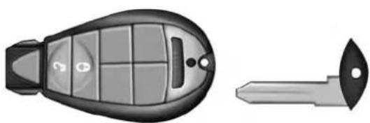
The Key Fob operates the ignition switch. Insert the square end of the key fob into the ignition switch located on the instrument panel and rotate to the desired position. It also contains the Remote Keyless Entry (RKE) transmitter and an emergency key, which stores in the rear of the Key Fob.
The emergency key allows for entry into the vehicle should the battery in the vehicle or the RKE transmitter go dead. You can keep the emergency key with you when valet parking.
To remove the emergency key, slide the mechanical latch at the top of the Key Fob sideways with your thumb and then pull the key out with your other hand.
THINGS TO KNOW BEFORE STARTING YOUR VEHICLE 13
NOTE: When using the emergency key to gain access to your vehicle, be aware that the security alarm may be triggered. Insert the Key Fob into the ignition and place the ignition in the ON/RUN mode to disarm the security system.
natural_image
Illustration of a car's side panel and its tip (no text or symbols)020207762
EmergencyKeyRemoval(IGNM)
14 THINGS TO KNOW BEFORE STARTING YOUR VEHICLE
KINKeyFob—Ifequipped
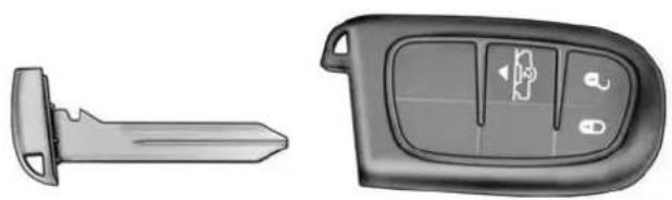
This KIN Key Fob allows the driver to operate the ignition switch with the push of a button, as long as the Remote Keyless Entry (RKE) transmitter is in the passenger compartment. The Keyless Ignition Node (KIN) has four operating positions, three of which are labeled and will illuminate when in position. The three positions are OFF, ACC, and ON/RUN. The fourth position is START, during start RUN will illuminate. It also contains the Remote Keyless Entry (RKE) transmitter and an emergency key, which stores in the rear of the Key Fob.
The emergency key allows for entry into the vehicle should the battery in the vehicle or the RKE transmitter go dead. You can keep the emergency key with you when valet parking.
To remove the emergency key, slide the mechanical latch on the backside of the Key Fob sideways with your thumb and then pull the key out with your other hand. NOTE: When using the emergency key to gain access to your vehicle, be aware that the security alarm may be triggered. Insert the Key Fob into the ignition and place the ignition in the ON/RUN mode to disarm the security system.
natural_image
Two views of a car key device: one showing a stylized key and the other a standard control panel with buttons (no text or symbols visible)0202006333
EmergencyKeyRemovalKeylessEnter-N-Go™Fob(KIN)
NOTE: You can insert the double-sided emergency key into the door lock cylinder with either side up.
Removing Key Fob From Ignition
Place the shift lever in PARK (if equipped with an automatic transmission). Turn the Key Fob to the OFF position and then remove the Key Fob.
NOTE:
- The power window switches, radio, power sunroof (if equipped), and power outlets will remain active for up to 10 minutes after the ignition switch is turned to the OFF position. Opening either front door will cancel this feature. Refer to “Uconnect® Settings” (Engine Off Options) in “Understanding Your Instrument Panel” for further information.
- For vehicles not equipped with a touchscreen radio, refer to "Electronic Vehicle Information Center (EVIC)/
THINGS TO KNOW BEFORE STARTING YOUR VEHICLE 15
Settings (Customer-Programmable Features)" in "Understanding Your Instrument Panel" for further information.
- For vehicles equipped with a touchscreen radio, refer to "Uconnect® Settings" in "Understanding Your Instrument Panel" for further information.
CAUTION!
- If your vehicle battery becomes slow or dead, your KeyFob will become locked in the ignition.
- DonotattempttoremovetheKeyFobwhileinthis condition,damagecouldoccurtotheKeyFobor ignitionmodule.Onlyremovetheemergencykey forlockingandunlockingthedoors.
- LeavetheKeyFobintheignitionandeither:
- JumpStartthevehicle.
- Chargethebattery.
16 THINGS TO KNOW BEFORE STARTING YOUR VEHICLE
WARNING!
- Beforeexitingavehicle,alwaysapplytheparking brake,shiftthetransmissionintoPARK,andpush ignitionbuttontoplaceignitioninOFFmode. Whenleavingthevehicle,alwayslockyourvehicle.
- Neverleavechildrenaloneinavehicle,orwith accesstoanunlockedvehicle.
- Allowingchildrentobeinavehicleunattendedis dangerousforanumberofreasons.Achildor otherscouldbeseriouslyorfatallyinjured.Childrenshouldbewarnednottotouchtheparking brake,brakepedalorthegaselector.
(Continued)
WARNING!(Continued)
- DonotleavetheKeyFobinornethevehicle,or inalocationaccessibletochildren,anddonot leavetheignitionofavehicleequipped with KeylessEnter-N-Go™intheACCorON/RUN mode.Achildcouldoperatepowerwindows,other controls,ormovethevehicle.
- Donotleavechildrenoranimalsinsideparked vehiclesinhotweather.Interiorheatbuild-upmay causeseriousinjuryordeath.
CAUTION!
An unlocked carisan invitation to thieves. Always removethe key from the ignition and lockalldoors when leaving the vehicle unattended.
Key-In-Ignition Reminder
Opening the driver's door when the Key Fob is in the ignition and the ignition switch position is OFF or ACC, a chime will sound to remind you to remove the Key Fob.
NOTE:
- "Keyed" Ignition systems will chime in OFF or ACC when the driver door is open.
- "Keyless" Ignition systems will chime in ACC or RUN when the driver door is open.
- If equipped with Electronic Vehicle Information Center (EVIC)/Driver Information Display (DID), the EVIC will display "Key In Ignition."
THINGS TO KNOW BEFORE STARTING YOUR VEHICLE 17
SENTRY KEY®
The Sentry Key® Immobilizer System prevents unauthorized vehicle operation by disabling the engine. The system does not need to be armed or activated. Operation is automatic, regardless of whether the vehicle is locked or unlocked.
The system uses a Key Fob with a factory-mated Remote Keyless Entry (RKE) transmitter, an Ignition Node Module, Keyless Ignition Node (KIN) and a RF receiver to prevent unauthorized vehicle operation. Therefore, only Key Fobs that are programmed to the vehicle can be used to start and operate the vehicle. The system will not allow the engine to crank if an invalid Key Fob is used to start and operate the vehicle. The system will shut the engine off in two seconds if an invalid Key Fob is used to start the engine.
NOTE: A Key Fob that has not been programmed is also considered an invalid key.
18 THINGS TO KNOW BEFORE STARTING YOUR VEHICLE
During normal operation, after turning on the ignition switch, the Vehicle Security Light will turn on for three seconds for a bulb check. If the light remains on after the bulb check, it indicates that there is a problem with the electronics. In addition, if the light begins to flash after the bulb check, it indicates that someone used an invalid Key Fob to try to start the engine. Either of these conditions will result in the engine being shut off after two seconds.
If the Vehicle Security Light turns on during normal vehicle operation (vehicle running for longer than 10 seconds), it indicates that there is a fault in the electronics. Should this occur, have the vehicle serviced as soon as possible by an authorized dealer.
CAUTION!
The SentryKey® Immobilizersystemis not compatible with some aftermarket remotestartingsystems. Useofthesesystemsmayresultinvehiclestarting problems and loss of security protection.
All of the Key Fobs provided with your new vehicle have been programmed to the vehicle electronics.
Replacement Keys
NOTE: Only Key Fobs that are programmed to the vehicle electronics can be used to start and operate the vehicle. Once a Key Fob is programmed to a vehicle, it cannot be programmed to any other vehicle.
CAUTION!
- AlwaysremovetheKeyFobsfromthevehicleand lockalldoorswhenleavingthevehicleunattended.
- ForvehiclesequippedwithKeylessEnter-N-Go™, alwaysremembertoplacetheignitionintheOFF position.
At the time of purchase, the original owner is provided with a four-digit Personal Identification Number (PIN). Keep the PIN in a secure location. This number is required for authorized dealer replacement of Key Fobs. Duplication of Key Fobs may be performed at an authorized dealer. This procedure consists of programming a blank Key Fob to the vehicle electronics. A blank Key Fob is one that has never been programmed.
THINGS TO KNOW BEFORE STARTING YOUR VEHICLE 19
NOTE: When having the Sentry Key® Immobilizer System serviced, bring all vehicle keys with you to an authorized dealer.
Customer Key Programming
Programming Key Fobs or RKE transmitters may be performed at an authorized dealer.
General Information
The Sentry Key® system complies with FCC rules part 15 and with RSS-210 of Industry Canada. Operation is subject to the following conditions:
- This device may not cause harmful interference.
- This device must accept any interference that may be received, including interference that may cause undesired operation.
20 THINGS TO KNOW BEFORE STARTING YOUR VEHICLE
NOTE: Changes or modifications not expressly approved by the party responsible for compliance could void the user's authority to operate the equipment.
VEHICLE SECURITY ALARM
The Vehicle Security Alarm monitors the vehicle doors and ignition for unauthorized operation. When the Vehicle Security Alarm is activated, interior switches for door locks are disabled. The system provides both audible and visible signals for the first three minutes the horn will sound and the headlights will turn on, the park lamps and/or turn signals will flash and Vehicle Security Light will flash repeatedly. For an additional 15 minutes only, the headlights will turn on, the park lamps and/or turn signals, and Vehicle Security Light will flash.
Rearming Of The System
The Vehicle Security Alarm will rearm itself after the 15 additional minutes of headlights and Vehicle Security Light flashing, if the system has not been disabled. If the condition which initiated the alarm is still present, the system will ignore that condition and monitor the remaining doors and ignition.
To Arm The System
Follow these steps to arm the Vehicle Security Alarm:
- Remove the key from the ignition system (refer to "Starting Procedures" in "Starting And Operating" for further information).
- For vehicles equipped with Keyless Enter-N-Go™, make sure the vehicle ignition system is "OFF."
-
For vehicles not equipped with Keyless Enter-N-Go™, make sure the vehicle ignition system is "OFF" and the key is physically removed from the ignition.
-
Perform one of the following methods to lock the vehicle:
-
Press LOCK on the interior power door lock switch with the driver and/or passenger door open.
- Press the LOCK button on the exterior Passive Entry Door Handle with a valid Key Fob available in the same exterior zone (refer to "Keyless Enter-N-Go™" in "Things To Know Before Starting Your Vehicle" for further information).
-
Press the LOCK button on the Remote Keyless Entry (RKE) transmitter.
-
If any doors are open, close them.
The Vehicle Security Alarm will set when you use the power door locks, or use the Remote Keyless Entry (RKE) transmitter to lock the doors. After all the doors are locked and closed, the Vehicle Security Light, in the instrument panel cluster, will flash rapidly for about
THINGS TO KNOW BEFORE STARTING YOUR VEHICLE 21
16 seconds to indicate that the alarm is being set. After the alarm is set, the Vehicle Security Light will flash at a slower rate to indicate that the system is armed.
To Disarm The System
The Vehicle Security Alarm can be disarmed using any of the following methods:
- Press the UNLOCK button on the Remote Keyless Entry (RKE) transmitter.
- Grasp the Passive Entry Unlock Door Handle with a valid Key Fob within 5 ft (1.5 m) of the passive entry door handle (if equipped, refer to "Keyless Enter-N-Go™" in "Things To Know Before Starting Your Vehicle" for further information).
- Cycle the vehicle ignition system out of the OFF position.
22 THINGS TO KNOW BEFORE STARTING YOUR VEHICLE
- For vehicles equipped with Keyless Enter-N-Go ^TM , press the Keyless Enter-N-Go ^TM Start/ Stop button (requires at least one valid Key Fob in the vehicle).
- For vehicles not equipped with Keyless Enter-N-Go ^TM , insert a valid key into the ignition switch and turn the key to the ON position.
The Vehicle Security Alarm is designed to protect your vehicle. However, you can create conditions where the system will give you a false alarm. If one of the previously described arming sequences has occurred, the Vehicle Security Alarm will arm regardless of whether you are in the vehicle or not. If you remain in the vehicle and open a door, the alarm will sound. If this occurs, disarm the Vehicle Security Alarm.
If the Vehicle Security Alarm is armed and the battery becomes disconnected, the Vehicle Security Alarm will remain armed when the battery is reconnected; the
exterior lights will flash, and the horn will sound. If this occurs, disarm the Vehicle Security Alarm.
Security System Manual Override
The Vehicle Security Alarm will not arm if you lock the doors using the manual door lock plunger.
ILLUMINATED APPROACH
The courtesy lights will turn on when you use the Remote Keyless Entry (RKE) transmitter to unlock the doors or open any door.
This feature also turns on the approach lighting in the outside mirrors (if equipped). Refer to "Mirrors" in "Understanding The Features Of Your Vehicle" for further information.
The lights will fade to off after approximately 30 seconds, or they will immediately fade to off once the ignition switch is turned to ON/RUN from the OFF position.
THINGS TO KNOW BEFORE STARTING YOUR VEHICLE 23
The front courtesy overhead console and door courtesy lights will not turn off if the dimmer control is in the "Dome ON" position (rotate horizontal thumb wheel on the bottom of the switch to the far right detent position).
The illuminated entry system will not operate if the dimmer control is in the “Dome OFF” position (rotate horizontal thumb wheel on the bottom of the switch to the far left detent position).
NOTE: If your vehicle is equipped with illuminated approach lights under the outside mirrors, they can be turned off by using the EVIC/DID controls (if NOT equipped with a touchscreen radio) or the Uconnect® radio (if equipped with a touchscreen radio). For further information, refer to "EVIC/DID" or "Uconnect® Settings" in "Understanding Your Instrument Panel."
REMOTE KEYLESS ENTRY (RKE) — IF EQUIPPED
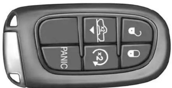
The RKE system allows you to lock or unlock all doors, tailgate, and the RamBox® (if equipped) as well as activate the Panic Alarm from distances up to approximately 33 ft (10 m) using a hand-held radio transmitter with integrated key. The transmitter does not need to be pointed at the vehicle to activate the system. Push and release the LOCK button on the RKE transmitter to lock all doors, and the tailgate. The turn signal lights will flash and the horn will chirp to acknowledge the signal.
NOTE: Inserting the Key Fob with RKE transmitter into the ignition switch disables the system from responding to any button pushes from that RKE transmitter. Driving at speeds 5 mph (8 km/h) and above disables the system from responding to all RKE transmitter buttons for all RKE transmitters.
24 THINGS TO KNOW BEFORE STARTING YOUR VEHICLE

natural_image
Top-down view of a black and white car with visible internal compartments and a 'PANIC' label (no other text or symbols)020207434
0202005004
KeyFobWithRemoteKeylessEntry(RKE)TransmitterKeyFobWithKeylessEnter-N-Go™Fob(KIN)
Remote Unlock The Doors
Push and release the UNLOCK button on the RKE transmitter once to unlock the driver's door (If EVIC is setup for driver door first, otherwise this will unlock all doors), or push the unlock button twice within five seconds to unlock all doors. The turn signal lights will flash to acknowledge the unlock signal. The illuminated entry system will also turn on.
RemoteKeyUnlock, DriverDoor/AllDoorsFirst
This feature lets you program the system to unlock either the driver's door or all doors on the first push of the UNLOCK button on the RKE transmitter. To change the current setting, proceed as follows:
- For vehicles not equipped with a touchscreen radio, refer to "Electronic Vehicle Information Center (EVIC)/ Settings (Customer-Programmable Features)" in "Understanding Your Instrument Panel" for further information.
THINGS TO KNOW BEFORE STARTING YOUR VEHICLE
25
- For vehicles equipped with a touchscreen radio, refer to "Uconnect® Settings" in "Understanding Your Instrument Panel" for further information.
NOTE: Pushing the LOCK button on the RKE transmitter while you are inside the vehicle will activate the Vehicle Security Alarm System. Opening a door with the Vehicle Security Alarm System activated will cause the alarm to sound. Push the UNLOCK button to deactivate the Vehicle Security Alarm System.
FlashLampsWithRemoteKeyLock
This feature will cause the turn signal lights to flash when the doors are locked or unlocked with the RKE transmitter. This feature can be turned on or turned off. To change the current setting, proceed as follows:
- For vehicles not equipped with a touchscreen radio, refer to "Electronic Vehicle Information Center (EVIC)/Settings (Customer-Programmable Features)" in "Understanding Your Instrument Panel" for further information.
26 THINGS TO KNOW BEFORE STARTING YOUR VEHICLE
- For vehicles equipped with a touchscreen radio, refer to "Uconnect® Settings" in "Understanding Your Instrument Panel" for further information.
To Lock The Doors
Push and release the LOCK button on the RKE transmitter to lock all doors. The turn signal lights will flash and the horn will chirp to acknowledge the signal.
SoundHornWithRemoteKeyLock
This feature will cause the horn to chirp when the doors are locked with the RKE transmitter. This feature can be turned on or turned off. To change the current setting, proceed as follows:
- For vehicles not equipped with a touchscreen radio, refer to "Electronic Vehicle Information Center (EVIC)/Settings (Customer-Programmable Features)" in "Understanding Your Instrument Panel" for further information.
- For vehicles equipped with a touchscreen radio, refer to "Uconnect® Settings" in "Understanding Your Instrument Panel" for further information.
NOTE: Pushing the LOCK button on the RKE transmitter while you are in the vehicle will activate the Vehicle Security Alarm System. Opening a door with the Vehicle Security Alarm System activated will cause the alarm to sound. Push the UNLOCK button to deactivate the Vehicle Security Alarm System.
Using The Panic Alarm
To turn the Panic Alarm feature ON or OFF, push and hold the PANIC button on the RKE transmitter for at least one second and release. When the Panic Alarm is on, the headlights will turn on, the park lights will flash, the horn will pulse on and off, and the interior lights will turn on.
The Panic Alarm will stay on for three minutes unless you turn it off by either pushing the PANIC button a second time or drive the vehicle at a speed of 5 mph (8 km/h) or greater.
NOTE:
- The interior lights will turn off if you turn the ignition switch to the ACC or ON/RUN position while the Panic Alarm is activated. However, the exterior lights and horn will remain on.
- You may need to be less than 35 ft (11 m) from the vehicle when using the RKE transmitter to turn off the Panic Alarm due to the radio frequency noises emitted by the system.
Programming Additional Transmitters
If you do not have a programmed RKE transmitter, contact your authorized dealer for details.
THINGS TO KNOW BEFORE STARTING YOUR VEHICLE 27
Transmitter Battery Replacement
The recommended replacement battery is one CR2032 battery.
NOTE:
- Perchlorate Material — special handling may apply. See www.dtsc.ca.gov/hazardouswaste/perchlorate
- Do not touch the battery terminals that are on the back housing or the printed circuit board.
- Remove the emergency key by sliding the mechanical latch on the back of the RKE transmitter sideways with your thumb and then pull the key out with your other hand.
28 THINGS TO KNOW BEFORE STARTING YOUR VEHICLE

natural_image
Top-down view of a car's key and dashboard (no text or symbols visible)020207436

natural_image
Two car key components shown: a gray key with a serrated tip and a black right-handled touchscreen control panel (no text or symbols visible)0202005021
IgnitionNodeModule(IGNM)EmergencyKeyRemovalKeylessIgnitionNode(KIN)EmergencyKeyRemoval
- Separating RKE halves requires screw removal – if equipped, and gently prying the two halves of the RKE transmitter apart. Make sure not to damage the seal during removal.
THINGS TO KNOW BEFORE STARTING YOUR VEHICLE 29

natural_image
Close-up of a mechanical component with internal channels and a small circular feature (no text or symbols visible)
natural_image
Illustration of a handheld device with a pointed tip and handle, no text or symbols present021334199
RemoveScrewFromTransmitterCaseSeparatingIgnitionNodeModule(IGNM)Transmitter Case
30 THINGS TO KNOW BEFORE STARTING YOUR VEHICLE

natural_image
Illustration of a knife inserted into a car key (no text or symbols)0213004940
SeparatingKeylessIgnitionNode(KIN)Transmitter Case
- Remove the battery by turning the back cover over (battery facing downward) and tapping it lightly on a solid surface such as a table or similar, then replace the battery. When replacing the battery, match the + sign on the battery to the + sign on the inside of the battery
clip, located on the back cover. Avoid touching the new battery with your fingers. Skin oils may cause battery deterioration. If you touch a battery, clean it with rubbing alcohol.
- To assemble the RKE transmitter case, snap the two halves together, reposition and secure the screw as shown in step #2 for removal.
General Information
This device complies with Part 15 of the FCC rules and RSS 210 of Industry Canada. Operation is subject to the following conditions:
• This device may not cause harmful interference.
- This device must accept any interference received, including interference that may cause undesired operation.
THINGS TO KNOW BEFORE STARTING YOUR VEHICLE 31
NOTE: Changes or modifications not expressly approved by the party responsible for compliance could void the user's authority to operate the equipment.
If your RKE transmitter fails to operate from a normal distance, check for these two conditions:
- A weak battery in the transmitter. The expected life of the battery is a minimum of three years.
- Closeness to a radio transmitter such as a radio station tower, airport transmitter, and some mobile or CB radios.
REMOTE STARTING SYSTEM — IF EQUIPPED

This system uses the Remote Keyless Entry (RKE) transmitter to start the engine conveniently from outside the vehicle while still maintaining security. The system has a range of nately 300 ft (91 m).
NOTE:
- The vehicle must be equipped with an automatic transmission to be equipped with Remote Start.
- Obstructions between the vehicle and the RKE transmitter may reduce this range.
How To Use Remote Start
All of the following conditions must be met before the engine will remote start:
- Shift lever in PARK
- Doors closed
- Hood closed
•HAZARD switch off - BRAKE switch inactive (brake pedal not pushed)
- Ignition key removed from ignition switch
32 THINGS TO KNOW BEFORE STARTING YOUR VEHICLE
- Battery at an acceptable charge level
•RKE PANIC button not pushed - Fuel meets minimum requirement
- System not disabled from previous remote start event
• Vehicle security alarm not active
WARNING!
- Donotstartorrunanengineinaclosedgarageor confinedarea.ExhaustgascontainsCarbonMonoxide(CO)whichisodorlessandcolorless.Carbon Monoxideispoisonousandcancauseseriousinjuryordeathwheninhaled.
- KeepRemoteKeylessEntry(RKE)transmitters awayfromchildren.OperationoftheRemoteStart System,windows,doorlocksorothercontrols couldcauseseriousinjuryordeath.
RemoteStartAbortMessage
The following messages will display in the EVIC/DID if the vehicle fails to remote start or exits remote start prematurely:
- Remote Start Cancelled — Door Open
- Remote Start Cancelled — Hood Ajar
- Remote Start Cancelled — Fuel Low
- Remote Start Cancelled — System Fault
- Remote Start Disabled — Start Vehicle to Reset
The EVIC/DID message stays active until the ignition is turned to the ON/RUN position.
ToEnterRemoteStartMode

Push and release the REMOTE START button on the RKE transmitter twice within five seconds. The parking lights will flash, vehicle doors will lock, and the horn will chirp twice (if programmed). Once the vehicle has started, the engine will run for 15 minutes.
NOTE:
- If your power door locks were unlocked, Remote Start will automatically lock the doors.
- If an engine fault is present or fuel level is low, the vehicle will start and then shut down in 10 seconds.
- The park lamps will turn on and remain on during Remote Start mode.
THINGS TO KNOW BEFORE STARTING YOUR VEHICLE 33
- For security, power window and power sunroof operation (if equipped) are disabled when the vehicle is in the Remote Start mode.
- The engine can be started two consecutive times (two 15-minute cycles) with the RKE transmitter. However, the ignition switch must be cycled to the ON/RUN position before you can repeat the start sequence for a third cycle.
ToExitRemoteStartModeWithoutDrivingThe Vehicle
Push and release the REMOTE START button one time or allow the engine to run for the entire 15-minute cycle.
NOTE: To avoid unintentional shut downs, the system will disable the one time push of the REMOTE START button for two seconds after receiving a valid Remote Start request.
34 THINGS TO KNOW BEFORE STARTING YOUR VEHICLE
ToExitRemoteStartModeAndDriveTheVehicle
Before the end of the 15-minute cycle, push and release the UNLOCK button on the RKE transmitter to unlock the doors and disarm the Vehicle Security Alarm System (if equipped). Then, prior to the end of the 15-minute cycle, cycle the ignition to the ON/RUN position.
RemoteStartComfortSystems—IfEquipped
When remote start is activated, the heated steering wheel and driver heated seat features will automatically turn on in cold weather. In warm weather, the driver vented seat feature will automatically turn on when the remote start is activated. These features will stay on through the duration of remote start or until the ignition switch is turned to the ON/RUN position.
The Remote Start Comfort System can be activated and deactivated through the Uconnect® System. For more information on Remote Start Comfort System operation refer to "Customer Programmable Features" in "Uconnect® Settings" in "Understanding Your Instrument Panel".
DOOR LOCKS
Manual Door Locks
Front and rear doors may be locked by moving the lock knob down or unlocked by moving the lock knob up.

natural_image
Interior view of a car showing the dashboard and seat area with no visible text or symbolsDoorLockKnob
Front doors may be opened with the inside door handle without lifting the lock knob.
Doors locked before closing will remain locked when closed.
THINGS TO KNOW BEFORE STARTING YOUR VEHICLE 35
The emergency key will unlock the driver door lock on your vehicle.
WARNING!
- Donotleavechildrenoranimalsinsideparked vehiclesinhotweather.Interiorheatbuild-upmay causeseriousinjuryordeath.
- Forpersonalsecurityandsafetyintheeventofan collision,lockthevehicledoorsasyoudriveas wellaswhenyouparkandleavethevehicle.
- Beforeexitingvehicle, alwaysturnthevehicle OFF, apply the parking brake, shift the automatic transmission into PARKorthemanual transmission into REVERSE, and push ignition button to placeignition in OFF mode.
- Neverleavechildrenaloneinavehicle,orwith accesstoanunlockedvehicle.
(Continued)
WARNING!(Continued)
- Allowingchildrentobeinavehicleunattendedis dangerousforanumberofreasons.Achildor otherscouldbeseriouslyorfatallyinjured.Childrenshouldbewarnednottotouchtheparking brake,brakepedalorthegearselector.
- DonotleavetheKeyFobinornethevehicle,or inalocationaccessibletochildren,anddonot leavetheignitionofavehicleequippedwith KeylessEnter-N-Go™intheACCorON/RUN mode.Achildcouldoperatepowerwindows,other controls,ormovethevehicle.
Power Door Locks — If Equipped
A power door LOCK switch is on each front door trim panel. Use this switch to lock or unlock the doors.

natural_image
Interior view of a car dashboard with a control panel and directional arrow (no text or symbols)PowerDoorLockSwitchLocation
If you push the power door LOCK switch while the Key Fob is in the ignition, and any front door is open, the power locks will not operate. This prevents you from accidentally locking your Key Fob in the vehicle. Removing the Key Fob or closing the door will allow the locks to
operate. A chime will sound if the Key Fob is in the ignition switch and a door is open, as a reminder to remove the Key Fob.
AutomaticDoorLocks—IfEquipped
The auto door lock feature default condition is enabled. When enabled, the door locks will lock automatically when the vehicle's speed exceeds 15 mph (24 km/h). The auto door lock feature can be enabled or disabled by your authorized dealer or through the Uconnect® Settings in your radio.
AutomaticDoorsUnlock—IfEquipped
This feature unlocks all of the doors of the vehicle when either front door is opened. This will occur only after the vehicle has been shifted into the PARK position after the vehicle has been driven (shifted out of PARK and all doors closed).
THINGS TO KNOW BEFORE STARTING YOUR VEHICLE 37
AutomaticDoorsUnlockProgramming—If Equipped
The Automatic Doors Unlock feature can be enabled or disabled as follows:
- For vehicles not equipped with a touchscreen radio, refer to "Electronic Vehicle Information Center (EVIC)/Settings (Customer-Programmable Features)" in "Understanding Your Instrument Panel" for further information.
- For vehicles equipped with a touchscreen radio, refer to "Uconnect® Settings" in "Understanding Your Instrument Panel" for further information.
NOTE: Use the Auto Unlock Doors feature in accordance with local laws.
38 THINGS TO KNOW BEFORE STARTING YOUR VEHICLE
Child-Protection Door Lock
To provide a safer environment for children riding in the rear seat, the rear doors (if equipped) of your vehicle have the Child-Protection Door Lock system.

natural_image
Close-up of a car door panel with a black arrow pointing to a corner detail (no text or symbols visible)Child-ProtectionDoorLockLocation
To use the system, open each rear door, use a flat blade screwdriver (or emergency key) and rotate the dial to
engage and disengage the Child-Protection locks. When the system on a door is engaged, that door can only be opened by using the outside door handle even if the inside door lock is in the unlocked position.

natural_image
Black and white illustration of a car with a camera and surrounding icons (no text or symbols)ChildLockControl
022605852
WARNING!
Avoidtrappinganyoneinavehicleinacollision. Rememberthatthereardoorscanonlybeopened fromtheoutsidewhentheChild-Protectionlocksare engaged.
NOTE:
- After setting the Child-Protection Door Lock system, always test the door from the inside to make certain it is in the desired position.
- For emergency exit with the system engaged, move the door lock switch to the UNLOCK position, roll down the window and open the door with the outside door handle.
THINGS TO KNOW BEFORE STARTING YOUR VEHICLE 39
KEYLESS ENTER-N-GO™
The Passive Entry system is an enhancement to the vehicle's Remote Keyless Entry (RKE) system and a feature of Keyless Enter-N-Go™. For further information, refer to "Keyless Enter-N-Go™" in "Starting And Operating." This feature allows you to lock and unlock the vehicle's door(s) without having to push the RKE transmitter lock or unlock buttons.
NOTE:
- Passive Entry may be programmed ON/OFF. Refer to "Uconnect® Settings" in "Understanding Your Instrument Panel" for further information.
- If wearing gloves on your hands, or if it has been raining on the Passive Entry door handle, the unlock sensitivity can be affected, resulting in a slower response time.
40 THINGS TO KNOW BEFORE STARTING YOUR VEHICLE
- If the vehicle is unlocked by the Passive Entry Door Handle, and no door goes ajar within 60 seconds, the vehicle will re-lock and if equipped will arm the security alarm.
- The vehicles security alarm can be armed/disarmed by pushing the passive entry key fob lock/unlock buttons (if equipped).
ToUnlockFromTheDriver'sSide:
With a valid Passive Entry RKE transmitter within 5 ft (1.5 m) of the driver door handle, grab the front driver door handle to unlock the driver's door automatically. The interior door panel lock knob will raise when the door is unlocked.

natural_image
Hand holding a car door handle, no visible text or symbolsGrabTheDoorHandleToUnlock
NOTE: If "Unlock All Doors 1st Press" is programmed, all doors will unlock when you grab hold of the front driver's door handle. To select between "Unlock Driver Door 1st Press" and "Unlock All Doors 1st Press," refer to "Uconnect® Settings" in "Understanding Your Instrument Panel" for further information.
ToUnlockFromThePassengerSide:
With a valid Passive Entry RKE transmitter within 5 ft (1.5 m) of the passenger door handle, grab the front passenger door handle to unlock all doors automatically. The interior door panel lock knob will raise when the door is unlocked.
NOTE: All doors will unlock when the front passenger door handle is grabbed regardless of the driver's door unlock preference setting ("Unlock Driver Door 1st Press" or "Unlock All Doors 1st Press").
PreventingInadvertentLockingOfPassiveEntryRKE TransmitterInVehicle
To minimize the possibility of unintentionally locking a Passive Entry RKE transmitter inside your vehicle, the Passive Entry system is equipped with an automatic door unlock feature which will function if the ignition switch is in the OFF position.
THINGS TO KNOW BEFORE STARTING YOUR VEHICLE 41
If one of the vehicle doors is open and the door panel switch is used to lock the vehicle, once all open doors have been closed the vehicle checks the inside and outside of the vehicle for any valid Passive Entry RKE transmitters. If one of the vehicle's Passive Entry RKE transmitters is detected inside the vehicle, and no other valid Passive Entry RKE transmitters are detected outside the vehicle, the Passive Entry System automatically unlocks all vehicle doors and chirps the horn three times (on the third attempt ALL doors will lock and the Passive Entry RKE transmitter can be locked in the vehicle).
ToLockTheVehicle'sDoors
With one of the vehicle's Passive Entry RKE transmitters within 5 ft (1.5 m) of the driver or passenger front door handles, push the door handle LOCK button to lock all doors.
42 THINGS TO KNOW BEFORE STARTING YOUR VEHICLE

natural_image
Hand pointing at a car door handle (no text or symbols visible)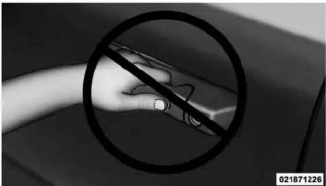
natural_image
Close-up of a hand holding a tool inside a circular target, no visible text or symbolsPushTheDoorHandleButtonToLockDoNOTGrabTheDoorHandleWhenLocking
Do NOT grab the door handle when pushing the door handle lock button. This could unlock the door(s).
THINGS TO KNOW BEFORE STARTING YOUR VEHICLE 43
NOTE:
• After pushing the door handle LOCK button, you must wait two seconds before you can lock or unlock the doors, using either Passive Entry door handle. This is done to allow you to check if the vehicle is locked by pulling the door handle, without the vehicle reacting and unlocking.
- The Passive Entry system will not operate if the RKE transmitter battery is dead.
The vehicle doors can also be locked by using the RKE transmitter lock button or the lock button located on the vehicle's interior door panel.
WINDOWS
Power Windows — If Equipped
natural_image
Interior view of a car dashboard with a control panel and directional arrow (no text or symbols)PowerWindowSwitches
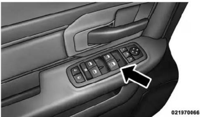
The control on the left front door panel has UP-DOWN switches that give you fingertip control of all power windows. There is a single opening and closing switch on
44 THINGS TO KNOW BEFORE STARTING YOUR VEHICLE
the front passenger door for passenger window control and on the rear doors of the Quad Cab and Crew Cab models. The windows will operate when the ignition switch is turned to the ON/RUN or ACC position, and for up to 10 minutes after the ignition is turned OFF or until a front door is opened.
NOTE: The Key Off Power Delay feature will allow the power windows to operate for up to 10 minutes after the ignition is turned OFF. This feature is cancelled when either front door is opened.
WARNING!
Neverleavechildrenunattendedinavehicle.Donot leavetheKeyFobinornearthevehicolorina locationaccessibletochildren, and donotleavethe ignitionofavehicleequippedwithKeylessEnter-N-Go™intheACCorON/RUNmode.Occupants,
WARNING!(Continued)
particularlyunattendedchildren,canbecomeen-trappedbythewindowswhileoperatingthepower windowswitches.Suchentrapmentmayresultin seriousinjuryordeath.
Auto-Down
Both the driver and front passenger window switch have an Auto-Down feature. Push the window switch past the first detent, release, and the window will go down automatically. To cancel the Auto-Down movement, operate the switch in either the up or down direction and release the switch.
To stop the window from going all the way down during the Auto-Down operation, pull up on the switch briefly.
To open the window part way, push to the first detent and release it when you want the window to stop.
(Continued)
THINGS TO KNOW BEFORE STARTING YOUR VEHICLE 45
Auto-UpFeatureWithAnti-PinchProtection (4-DoorModelsDriverAndFrontPassengerDoor Only)—IfEquipped
Lift the window switch fully upward to the second detent, release, and the window will go up automatically.
To stop the window from going all the way up during the Auto Up operation, push down on the switch briefly.
To close the window part way, lift the window switch to the first detent and release when you want the window to stop.
NOTE: If the window runs into any obstacle during the auto-closure, it will reverse direction and then go back down. Remove the obstacle and use the window switch again to close the window. Any impact due to rough road conditions may trigger the auto reverse function unexpectedly during auto closure. If this happens, pull the switch lightly to the first detent and hold to close the window manually.
WARNING!
Thereisnoanti-pinchprotectionwhenthewindow isalmostclosed.Besuretoclearallobjectsfromthe windowbeforeclosing.
ResetAuto-Up
Should the Auto Up feature stop working, the window may need to be reset. To reset Auto Up:
- Make sure the door is fully closed.
- Pull the window switch up to close the window completely and continue to hold the switch up for an additional two seconds after the window is closed.
- Push the window switch down firmly to the second detent to open the window completely and continue to hold the switch down for an additional two seconds after the window is fully open.
46 THINGS TO KNOW BEFORE STARTING YOUR VEHICLE WindowLOCKOUTSwitch(4-DoorModelsOnly)
The window LOCKOUT switch on the driver's door allows you to disable the window control on the rear passenger doors. To disable the window controls on the rear passenger doors, push the window LOCK button into the latched or down position. To enable the window controls, push the window LOCK button again and return the switch to the released or up position.

natural_image
Interior view of a car dashboard with a control panel and directional arrow (no text or symbols)WindowLockoutSwitch
Wind Buffeting
Wind buffeting can be described as the perception of pressure on the ears or a helicopter-type sound in the ears. Your vehicle may exhibit wind buffeting with the windows down, or the sunroof (if equipped) in certain open or partially open positions. This is a normal occurrence and can be minimized. If the buffeting occurs with the rear windows open, then open the front and rear windows together to minimize the buffeting. If the buffeting occurs with the sunroof open, adjust the sunroof opening to minimize the buffeting.
OCCUPANT RESTRAINT SYSTEMS
Some of the most important safety features in your vehicle are the restraint systems:
- Seat Belt Systems
• Supplemental Restraint Systems (SRS) Air Bags - Child Restraints
THINGS TO KNOW BEFORE STARTING YOUR VEHICLE 47
Important Safety Precautions
Please pay close attention to the information in this section. It tells you how to use your restraint system properly, to keep you and your passengers as safe as possible.
Here are some simple steps you can take to minimize the risk of harm from a deploying air bag:
- Children 12 years old and under should always ride buckled up in a vehicle with a rear seat.
- If a child from 2 to 12 years old (not in a rear-facing child restraint) must ride in the front passenger seat, move the seat as far back as possible and use the proper child restraint. (Refer to "Child Restraints")
- Children that are not big enough to wear the vehicle seat belt properly (Refer to "Child Restraints") should be secured in a vehicle with a rear seat in child
48 THINGS TO KNOW BEFORE STARTING YOUR VEHICLE
restraints or belt-positioning booster seats. Older children who do not use child restraints or belt-positioning booster seats should ride properly buckled up in a vehicle with a rear seat.
- Never allow children to slide the shoulder belt behind them or under their arm.
- You should read the instructions provided with your child restraint to make sure that you are using it properly.
- All occupants should always wear their lap and shoulder belts properly.
- The driver and front passenger seats should be moved back as far as practical to allow the Advanced Front Air Bags room to inflate.
- Do not lean against the door or window. If your vehicle has side air bags, and deployment occurs, the
side air bags will inflate forcefully into the space between you and the door and you could be injured.
- If the air bag system in this vehicle needs to be modified to accommodate a disabled person, contact the Customer Center. Phone numbers are provided under "If You Need Consumer Assistance."
WARNING!
- Neverplacearear-facingchildrestraintinfrontof anairbag.AdeployingPassengerAdvancedFront AirBagcancausedeathorseriousinjurytoachild 12yearsoryounger,includingachildinarear-facingchildrestraint.
- Onlyuserear-facingchildrestraintinvehicle witharearseat.
Seat Belt Systems
Buckle up even though you are an excellent driver, even on short trips. Someone on the road may be a poor driver and could cause a collision that includes you. This can happen far away from home or on your own street.
Research has shown that seat belts save lives, and they can reduce the seriousness of injuries in a collision. Some of the worst injuries happen when people are thrown from the vehicle. Seat belts reduce the possibility of ejection and the risk of injury caused by striking the inside of the vehicle. Everyone in a motor vehicle should be belted at all times.
EnhancedSeatBeltUseReminderSystem (BeltAlert)
3 BeltAlert is a feature intended to remind the driver and outboard front passenger (if equipped with outboard front passenger BeltAlert) to buckle their seat belts. The feature is active whenever the ignition is in
THINGS TO KNOW BEFORE STARTING YOUR VEHICLE 49
the START or ON/RUN position. If the driver or outboard front seat passenger is unbelted, the Seat Belt Reminder Light will turn on and remain on until both outboard front seat belts are buckled.
The BeltAlert warning sequence begins after the vehicle speed is over 5 MPH (8 km/h) by blinking the Seat Belt Reminder Light and sounding an intermittent chime. Once the sequence starts, it will continue for the entire duration or until the respective seat belts are buckled. After the sequence completes, the Seat Belt Reminder Light remains illuminated until the respective seat belts are buckled. The driver should instruct all other occupants to buckle their seat belts. If an outboard front seat belt is unbuckled while traveling at speeds greater than 5 MPH (8 km/h), BeltAlert will provide both audio and visual notification.
The outboard front passenger seat BeltAlert is not active when the outboard front passenger seat is unoccupied.
50 THINGS TO KNOW BEFORE STARTING YOUR VEHICLE
BeltAlert may be triggered when an animal or heavy object is on the outboard front passenger seat or when the seat is folded flat (if equipped). It is recommended that pets be restrained in the rear seat (if equipped) in pet harnesses or pet carriers that are secured by seat belts, and cargo is properly stowed.
BeltAlert can be activated or deactivated by your authorized dealer. Chrysler Group LLC does not recommend deactivating BeltAlert.
NOTE: If BeltAlert has been deactivated, the Seat Belt Reminder Light will continue to illuminate while the driver's or outboard front passenger's (if equipped with BeltAlert) seat belt remains unbuckled.
Lap/ShoulderBelts
All seating positions except the Quad Cab®, Mega Cab® and Crew Cab front center seating position have combination lap/shoulder belts.
The seat belt webbing retractor will lock only during very sudden stops or collisions. This feature allows the shoulder part of the seat belt to move freely with you under normal conditions. However, in a collision the seat belt will lock and reduce your risk of striking the inside of the vehicle or being thrown out of the vehicle.
WARNING!
- Relyingontheairbagsalonecouldleadtomore severeinjuriesinacollision.Theairbagswork withyourseatbelttorestrainyouproperly.In somecollisions,theairbagswon'tdeployatall. Alwayswearyourseatbelteventhoughyouhave airbags.
(Continued)
THINGS TO KNOW BEFORE STARTING YOUR VEHICLE 51
WARNING!(Continued)
- Inacollision, you and your passengers can suffer much greater injuries if you are not properly buckledup. You can strike the interior of your vehicle or other passengers, or you can be thrown out of the vehicle. Always besure you and others in your vehicle are buckledup properly.
- Itisdangeroustorideinacargoarea,insideor outsideofvehicle.Inacollision,peopleridingin theseareasaremorelikelytobeseriouslyinjured orkilled.
- Donotallowpeopletorideinanyareaofyour vehiclethatisnotequippedwithseatsandseat belts.
- Besureeveryoneinyourvehicleisinaseatand usingaseatbeltproperly.
(Continued)
WARNING!(Continued)
- Wearingyourseatbeltincorrectlycouldmakeyour injuriesinacollisionmuchworse.Youmight sufferinternalinjuries,oryoucouldevenslideout oftheseatbelt.Followtheseinstructionstowear yourseatbeltsafelyandtokeepyourpassengers safe,too.
- Twopeopleshouldneverbebeltedintoasingle seatbelt.Peoplebeltedtogethercancrashintoone anotherinacollision,hurtingoneanotherbadly. Neverusealap/shoulderbeltoralapbeltformore thanoneperson,nomatterwhattheirsize.
- Alapbeltworntoohighcanincreasetheriskof injuryinacollision. Theseatbeltforceswon'tbeat thestronghipandpelvicbones,butacrossyour abdomen.Alwayswearthelappartofyourseat beltaslowaspossibleandkeepitsnug.
(Continued)
52 THINGS TO KNOW BEFORE STARTING YOUR VEHICLE
WARNING!(Continued)
- Atwistedseatbeltmaynotprotectyouproperly.In acollision,itcouldevencutintoyou.Besurethe seatbeltisflatagainstyourbody,withouttwists.If youcan'tstraightenaseatbeltinyourvehicle,take ittoyourauthorizeddealerimmediatelyandhave itfixed.
- Aseatbeltthatisbuckledintothewrongbuckle willnotprotectyouproperly. Thelapportioncould ridetoohighonyourbody,possiblycausinginternalinjuries. Alwaysbuckleyourseatbeltintothe bucklenearestyou.
- Aseatbeltthatistooloosewillnotprotectyou properly.Inasuddenstop,youcouldmovetoofar forward,increasingthepossibilityofinjury.Wear yourseatbeltsnugly.
WARNING!(Continued)
- Aseatbeltthatiswornunderyourarmisdangerous.Yourbodycouldstriketheinsidesurfacesof thevehicleinacollision,increasingheadandneck injury.Aseatbeltwornunderthearmcancause internalinjuries.Ribsaren'tasstrongassshoulder bones.Weartheseatbeltoveryourshouldersothat yourstrongestboneswilltaketheforceinacollision.
- Ashoulderbeltplacedbehindyouwillnotprotect youfrominjuryduringacollision.Youaremore likelytohityourheadinacollisionifyoudonot wearyourshoulderbelt.Thelapandshoulderbelt aremeanttobeusedtogether.
(Continued)
(Continued)
THINGS TO KNOW BEFORE STARTING YOUR VEHICLE 53
WARNING!(Continued)
- Afrayedortornseatbeltcould dripapartina collisionandleaveyouwithnoprotection. Inspect theseatbeltsystemperiodically, checkingforcuts, frays,orlooseparts. Damagedpartsmustbereplacedimmediately. Donotdisassembleormodify theseatbeltsystem. Seatbeltassembliesmustbe replacedafteracollision.
Lap/ShoulderBeltOperatingInstructions
-
Enter the vehicle and close the door. Sit back and adjust the seat.
-
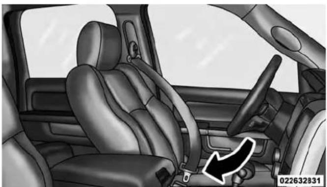
The seat belt latch plate is above the back of the front seat, and next to your arm in the rear seat (for vehicles equipped with a rear seat). Grasp the latch plate and pull out the seat belt. Slide the latch plate up the webbing as far as necessary to allow the seat belt to go around your lap.

natural_image
Interior view of a car showing seatbelt and dashboard (no text or symbols visible)PullingOutTheLatchPlate
- When the seat belt is long enough to fit, insert the latch plate into the buckle until you hear a "click."
54 THINGS TO KNOW BEFORE STARTING YOUR VEHICLE
natural_image
Interior view of a car showing the seatbelt and dashboard (no text or symbols visible)
natural_image
Interior view of a car showing seatbelt and dashboard with two arrows indicating directions (no text or symbols)InsertingLatchPlateIntoBucklePositioningTheLapBelt
-
Position the lap belt so that it is snug and lies low across your hips, below your abdomen. To remove slack in the lap belt portion, pull up on the shoulder belt. To loosen the lap belt if it is too tight, tilt the latch plate and pull on the lap belt. A snug seat belt reduces the risk of sliding under the seat belt in a collision.
-
Position the shoulder belt across the shoulder and chest with minimal, if any slack so that it is comfortable and not resting on your neck. The retractor will withdraw any slack in the shoulder belt.
THINGS TO KNOW BEFORE STARTING YOUR VEHICLE 55
- To release the seat belt, push the red button on the buckle. The seat belt will automatically retract to its stowed position. If necessary, slide the latch plate down the webbing to allow the seat belt to retract fully.
FirstRowCenterSeatBeltOperatingInstructions
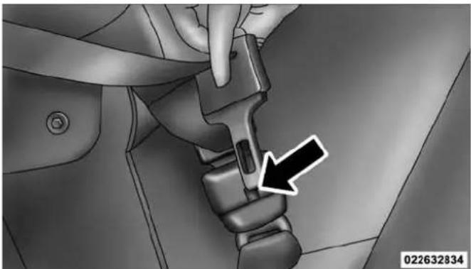
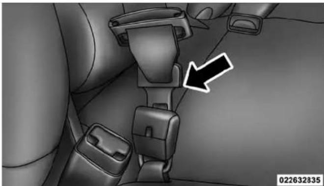
The first row center seat belt features a seat belt with a mini-latch and mini-buckle, which allows the seat belt to detach from the lower anchor when the seat is folded. The mini-buckle and seat belt can then be stored out of the way in the seat for added convenience.
- Remove the mini-latch and regular latch from its stowed position on the seat.
natural_image
Close-up of a hand using a tool to adjust a car seatbelt, with a black arrow pointing to the button (no text or symbols visible)DetachingBuckleWithSeatBeltTongue
56 THINGS TO KNOW BEFORE STARTING YOUR VEHICLE
natural_image
Interior view of a car seatbelt assembly with a black arrow pointing to the seat (no text or symbols visible)InsertingLatchPlateInUsePosition

natural_image
Medical procedure image showing a surgical tool inserted into a car seatbelt, with two arrows indicating specific anatomical points (no text or symbols present)- Grasp the mini-latch plate and pull the seat belt over the seat.
-
Route the shoulder belt to the inside of the [right/ left] head restraint.
-
When the seat belt is long enough to fit, insert the mini-latch plate into the mini-buckle until you hear a "click."
- Sit back in seat. Slide the regular latch plate up the webbing as far as necessary to allow the seat belt to go around your lap.
- When the seat belt is long enough to fit, insert the latch plate into the buckle until you hear a "click."
- Position the lap belt so that it is snug and lies low across your hips, below your abdomen. To remove slack in the lap belt portion, pull up on the shoulder belt. To loosen the lap belt if it is too tight, pull on the lap belt. A snug seat belt reduces the risk of sliding under the seat belt in a collision.
- Position the shoulder belt on your chest so that it is comfortable and not resting on your neck. The retractor will withdraw any slack in the seat belt.
THINGS TO KNOW BEFORE STARTING YOUR VEHICLE 57
- To release the seat belt, push the red button on the buckle.
- To disengage the mini-latch from the mini-buckle for storage, insert the regular latch plate into the center red slot on the mini-buckle. The seat belt will automatically retract to its stowed position. If necessary, slide the latch plate down the webbing to allow the seat belt to retract fully. Insert the mini-latch plate and regular latch plate into its stowed position.
WARNING!
- If themini-latchandmini-bucklearenotproperly connected when theseatbeltisused by an occupant, theseatbeltwill not be able to provide proper restraint and will increase risk of injury in acollision.
(Continued)
58 THINGS TO KNOW BEFORE STARTING YOUR VEHICLE
WARNING!(Continued)
- Whenreattachingthemini-latchandmini-buckle, ensuretheseatbeltwebbingisnottwisted. If the webbingistwisted, followtheprecedingproceduretodetachthemini-latchandmini-buckle, untwistthewebbing, andreattachthemini-latch andmini-buckle.
Lap/ShoulderBeltUntwistingProcedure
Use the following procedure to untwist a twisted lap/shoulder belt.
- Position the latch plate as close as possible to the anchor point.
-
At about 6 to 12 inches (15 to 30 cm) above the latch plate, grasp and twist the seat belt webbing 180^ to create a fold that begins immediately above the latch plate.
-
Slide the latch plate upward over the folded webbing. The folded webbing must enter the slot at the top of the latch plate.
- Continue to slide the latch plate up until it clears the folded webbing and the seat belt is no longer twisted.
AdjustableUpperShoulderBeltAnchorage
In the driver and front passenger seats, the top of the shoulder belt can be adjusted upward or downward to position the seat belt away from your neck. Push or squeeze the anchorage button to release the anchorage, and move it up or down to the position that serves you best.

natural_image
Interior view of a car seatbelt with directional arrows indicating seat movement (no text or symbols)AdjustableAnchorage
As a guide, if you are shorter than average, you will prefer the shoulder belt anchorage in a lower position, and if you are taller than average, you will prefer the shoulder belt anchorage in a higher position. After you release the anchorage button, try to move it up or down to make sure that it is locked in position.
THINGS TO KNOW BEFORE STARTING YOUR VEHICLE 59
NOTE: The adjustable upper shoulder belt anchorage is equipped with an Easy Up feature. This feature allows the shoulder belt anchorage to be adjusted in the upward position without pushing or squeezing the release button. To verify the shoulder belt anchorage is latched, pull downward on the shoulder belt anchorage until it is locked into position.
SeatBeltExtender
If a seat belt is not long enough to fit properly, even when the webbing is fully extended and the adjustable upper shoulder belt anchorage (if equipped) is in its lowest position, your authorized dealer can provide you with a Seat Belt Extender. The Seat Belt Extender should be used only if the existing seat belt is not long enough. When the Seat Belt Extender is not required for a different occupant, it must be removed.
WARNING!
- ONLYuseaSeatBeltExtenderifitisphysically requiredinordertoproperlyfittheoriginalseat beltsystem.DONOTUSEtheSeatBeltExtender if,whenworn,thedistancebetweenthefrontedge oftheSeatBeltExtenderbuckleandthecenterof theoccupant'sbodyisLESSthan6inches.
- UsingaSeatBeltExtenderwhennotneededcan increasetheriskofseriousinjuryordeathina collision.OnlyusetheSeatBeltExtenderwhenthe lapbeltisnotlongenoughandonlyuseinthe recommendedseatingpositions.Removeandstore theSeatBeltExtenderwhennotneeded.
SeatBeltsAndPregnantWomen
We recommend that pregnant women use the seat belts throughout their pregnancy. Keeping the mother safe is the best way to keep the baby safe.
Pregnant women should wear the lap part of the seat belt across the thighs and as snug across the hips as possible. Keep the seat belt low so that it does not come across the abdomen. That way the strong bones of the hips will take the force if there is a collision.
SeatBeltPretensioner—(IfEquipped)
The front seat belt system may be equipped with pretensioning devices that are designed to remove slack from the seat belt in the event of a collision. These devices may improve the performance of the seat belt by removing slack from the seat belt early in a collision. Pretensioners work for all size occupants, including those in child restraints.
NOTE: These devices are not a substitute for proper seat belt placement by the occupant. The seat belt still must be worn snugly and positioned properly.
The pretensioners are triggered by the Occupant Restraint Controller (ORC). Like the air bags, the pretensioners are single use items. A deployed pretensioner or a deployed air bag must be replaced immediately.
EnergyManagementFeature—IfEquipped
This vehicle has a seat belt system with an Energy Management feature in the front seating positions that may help further reduce the risk of injury in the event of a collision. This seat belt system has a retractor assembly that is designed to release webbing in a controlled manner.
CenterLapBelts
The center seating position for the Quad Cab®, Mega Cab® and Crew Cab front seat has a lap belt only. To buckle the lap belt, slide the latch plate into the buckle until you hear a "click."To lengthen the lap belt, tilt the latch plate and pull.
THINGS TO KNOW BEFORE STARTING YOUR VEHICLE 61
To remove slack, pull the loose end of the webbing. Wear the lap belt snug against the hips. Sit back and upright in the seat, then adjust the seat belt as tightly as is comfortable.
AutomaticLockingRetractors(ALR)-IfEquipped
The seat belts in the passenger seating positions may be equipped with a Switchable Automatic Locking Retractor (ALR) which is used to secure a child restraint system. For additional information, refer to “Installing Child Restraints Using The Vehicle Seat Belt” under the “Child Restraints” section of this manual. The table below defines the type of feature for each seating position.
62 THINGS TO KNOW BEFORE STARTING YOUR VEHICLE

0226059225

0226061828
StandardCabQuadCab®/MegaCab®/CrewCab
- ALR = Switchable Automatic Locking Retractor If the passenger seating position is equipped with an ALR and is being used for normal usage, only pull the seat belt webbing out far enough to comfortably wrap around the occupant's mid-section so as to not activate the ALR. If the ALR is activated, you will hear a clicking
THINGS TO KNOW BEFORE STARTING YOUR VEHICLE 63
sound as the seat belt retracts. Allow the webbing to retract completely in this case and then carefully pull out only the amount of webbing necessary to comfortably wrap around the occupant's mid-section. Slide the latch plate into the buckle until you hear a "click."
In Automatic Locking Mode, the shoulder belt is automatically pre-locked. The seat belt will still retract to remove any slack in the shoulder belt. Use the Automatic Locking Mode anytime a child restraint is installed in a seating position that has a seat belt with this feature. Children 12 years old and under should always be properly restrained in a vehicle with a rear seat.
WARNING!
- Neverplacearear-facingchildrestraintinfrontof anairbag.AdeployingPassengerAdvancedFront AirBagcancausedeathorseriousinjurytoachild 12yearsoryounger,includingachildinarear-facingchildrestraint.
- Onlyuserear-facingchildrestraintinvehicle witharearseat.
HowToEngageTheAutomaticLockingMode
- Buckle the combination lap and shoulder belt.
- Grasp the shoulder portion and pull downward until the entire seat belt is extracted.
- Allow the seat belt to retract. As the seat belt retracts, you will hear a clicking sound. This indicates the seat belt is now in the Automatic Locking Mode.
64 THINGS TO KNOW BEFORE STARTING YOUR VEHICLE
HowToDisengageTheAutomaticLockingMode
Unbuckle the combination lap/shoulder belt and allow it to retract completely to disengage the Automatic Locking Mode and activate the vehicle sensitive (emergency) locking mode.
WARNING!
- Theseatbeltassemblymustbereplacedifthe switchableAutomaticLockingRetractor(ALR)featureoranyotherseatbeltfunctionisnotworking properlywhencheckedaccordingtotheproceduresintheServiceManual.
- Failuretoreplacetheseatbeltassemblycould increasetheriskofinjuryincollisions.
(Continued)
WARNING!(Continued)
- DonotusetheAutomaticLockingModetorestrain occupantswhoarewearingtheseatbeltorchildren whoareusingboosterseats. Thelockedmodeis onlyusedtoinstallrear-facingorforward-facing childrestraintsthathaveaharnessforrestraining thechild.
Supplemental Restraint System (SRS)
AirBagSystemComponents
Your vehicle may be equipped with the following air bag system components:
•Occupant Restraint Controller (ORC)
• Air Bag Warning Light
•Steering Wheel and Column
- Instrument Panel
THINGS TO KNOW BEFORE STARTING YOUR VEHICLE 65
•Knee Impact Bolsters
• Advanced Front Air Bags
• Supplemental Side Air Bags
- Front And Side Impact Sensors — If Equipped
- Seat Belt Pretenioners
- Seat Belt Buckle Switch
AdvancedFrontAirBags
This vehicle has Advanced Front Air Bags for both the driver and front passenger as a supplement to the seat belt restraint systems. The driver's Advanced Front Air Bag is mounted in the center of the steering wheel. The passenger's Advanced Front Air Bag is mounted in the instrument panel, above the glove compartment. The words "SRS AIRBAG" or "AIRBAG" are embossed on the air bag covers.
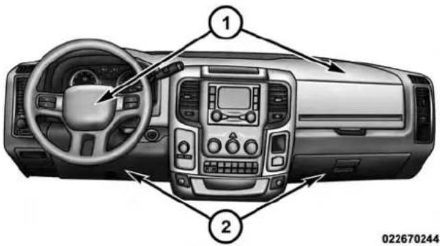
AdvancedFrontAirBagAndKneeBolsterLocations
1 — Driver And Passenger Advanced Front Air Bags
2 — Driver/Passenger Knee Impact Bolsters
WARNING!
- Beingtooclosetothesteeringwheelorinstrument panelduringAdvancedFrontAirBagdeployment couldcauseseriousinjury,includingdeath.Air bagsneedroomtoinflate.Sitback,comfortably extendingyourarmstoreachthesteeringwheelor instrumentpanel.
- Neverplacearear-facingchildrestraintinfrontof anairbag.AdeployingPassengerAdvancedFront AirBagcancausedeathorseriousinjurytoachild 12yearsoryounger,includingachildinarear-facingchildrestraint.
- Onlyusearear-facingchildrestraintinvehicle witharearseat.
AdvancedFrontAirBagFeatures
The Advanced Front Air Bag system has multistage driver and front passenger air bags. This system provides output appropriate to the severity and type of collision as determined by the Occupant Restraint Controller (ORC), which may receive information from the front impact sensors (if equipped) or other system components.
The first stage inflator is triggered immediately during an impact that requires air bag deployment. A low energy output is used in less severe collisions. A higher energy output is used for more severe collisions.
This vehicle may be equipped with a driver and/or front passenger seat belt buckle switch that detects whether the driver or front passenger seat belt is buckled. The seat belt buckle switch may adjust the inflation rate of the Advanced Front Air Bags.
THINGS TO KNOW BEFORE STARTING YOUR VEHICLE 67
WARNING!
- Noobjectsshouldbeplacedoverorneartheair bagontheinstrumentpanelsteeringwheel, becauseanysuchobjectscouldcauseharmifthe vehicleisinacollisionsevereenoughtocausethe airbagstoinflate.
- Donotputanythingonoraroundtheairbag coversorattempttoopenthemmanually.Youmay damagetheairbagsandyoucouldbeinjured becausetheairbagsmaynolongerbefunctional. Theprotectivecoversfortheairbagcushionsare designedtoopenonlywhentheairbagsare inflating.
(Continued)
WARNING!(Continued)
- Relyingontheairbagsalonecouldleadtomore severeinjuriesinacollision.Theairbagswork withyourseatbelttorestrainyouproperly.In somecollisions,airbagswon'tdeployatall.Alwayswearyourseatbeltseventhoughyouhaveair bags.
AdvancedFrontAirBagOperation
Advanced Front Air Bags are designed to provide additional protection by supplementing the seat belts. Advanced Front Air Bags are not expected to reduce the risk of injury in rear, side, or rollover collisions. The Advanced Front Air Bags will not deploy in all frontal collisions, including some that may produce substantial vehicle damage — for example, some pole collisions, truck underrides, and angle offset collisions.
68 THINGS TO KNOW BEFORE STARTING YOUR VEHICLE
On the other hand, depending on the type and location of impact, Advanced Front Air Bags may deploy in crashes with little vehicle front-end damage but that produce a severe initial deceleration.
Because air bag sensors measure vehicle deceleration over time, vehicle speed and damage by themselves are not good indicators of whether or not an air bag should have deployed.
Seat belts are necessary for your protection in all collisions, and also are needed to help keep you in position, away from an inflating air bag.
When the ORC detects a collision requiring the Advanced Front Air Bags, it signals the inflator units. A large quantity of non-toxic gas is generated to inflate the Advanced Front Air Bags.
The steering wheel hub trim cover and the upper right side of the instrument panel separate and fold out of the
way as the air bags inflate to their full size. The Advanced Front Air Bags fully inflate in less time than it takes to blink your eyes. The air bags then quickly deflate while helping to restrain the driver and front passenger.
KneeImpactBolsters
The Knee Impact Bolsters help protect the knees of the driver and front passenger, and position the front occupants for improved interaction with the Advanced Front Air Bags.
WARNING!
- Donotdrill, cut, ortamper with the knee impact bolstersinany way.
- Donotmountanyaccessoriestothekneeimpact bolsterssuchasalarmlights, stereos, citizenband radios, etc.
IfADeploymentOccurs
The Advanced Front Air Bags are designed to deflate immediately after deployment.
NOTE: Front and/or side air bags will not deploy in all collisions. This does not mean something is wrong with the air bag system.
If you do have a collision, which deploys the air bags, any or all of the following may occur:
- The air bag material may sometimes cause abrasions and/or skin reddening to the occupants as the air bags deploy and unfold. The abrasions are similar to friction rope burns or those you might get sliding along a carpet or gymnasium floor. They are not caused by contact with chemicals. They are not permanent and normally heal quickly. However, if you haven't healed significantly within a few days, or if you have any blistering, see your doctor immediately.
THINGS TO KNOW BEFORE STARTING YOUR VEHICLE 69
- As the air bags deflate, you may see some smoke-like particles. The particles are a normal by-product of the process that generates the non-toxic gas used for air bag inflation. These airborne particles may irritate the skin, eyes, nose, or throat. If you have skin or eye irritation, rinse the area with cool water. For nose or throat irritation, move to fresh air. If the irritation continues, see your doctor. If these particles settle on your clothing, follow the garment manufacturer's instructions for cleaning.
Do not drive your vehicle after the air bags have deployed. If you are involved in another collision, the air bags will not be in place to protect you.
WARNING!
Deployedairbagsandseatbeltpretensionerscannot protectyouinanothercollision.Havetheairbags,
(Continued)
70 THINGS TO KNOW BEFORE STARTING YOUR VEHICLE
WARNING!(Continued)
seatbeltpretensioners, and theseatbeltretractor assemblies replaced by an authorized dealer immediately. Also, havetheOccupantRestraintController Systemservicedaswell.
NOTE:
- Air bag covers may not be obvious in the interior trim, but they will open during air bag deployment.
- After any collision, the vehicle should be taken to an authorized dealer immediately.
EnhancedAccidentResponseSystem
In the event of an impact, if the communication network remains intact, and the power remains intact, depending on the nature of the event, the ORC will determine whether to have the Enhanced Accident Response System perform the following functions:
- Cut off fuel to the engine.
- Flash hazard lights as long as the battery has power or until the ignition switch is turned to the "OFF" position.
- Turn on the interior lights, which remain on as long as the battery has power or until the ignition switch is turned to the "OFF" position.
- Unlock the doors automatically.
SystemResetProcedure
In order to reset the Enhanced Accident Response System functions after an event, the ignition switch must be changed from ignition START or ON/RUN to ignition OFF.
AirBagWarningLight

The air bags must be ready to inflate for your protection in a collision. The Occupant Restraint Controller (ORC) monitors the internal circuits and interconnecting wiring associated with air bag system electrical components.
The ORC monitors the readiness of the electronic parts of the air bag system whenever the ignition is in the START or ON/RUN position. If the ignition is in the OFF position or in the ACC position, the air bag system is not on and the air bags will not inflate.
THINGS TO KNOW BEFORE STARTING YOUR VEHICLE
71
The ORC contains a backup power supply system that may deploy the air bags even if the battery loses power or it becomes disconnected prior to deployment.
The ORC turns on the Air Bag Warning Light in the instrument panel for approximately four to eight seconds for a self-check when the ignition is first placed in the ON/RUN position. After the self-check, the Air Bag Warning Light will turn off. If the ORC detects a malfunction in any part of the system, it turns on the Air Bag Warning Light, either momentarily or continuously. A single chime will sound to alert you if the light comes on again after initial startup.
The ORC also includes diagnostics that will illuminate the instrument panel Air Bag Warning Light if a malfunction is detected that could affect the air bag system. The diagnostics also record the nature of the malfunction.
While the air bag system is designed to be maintenance
72 THINGS TO KNOW BEFORE STARTING YOUR VEHICLE
free, if any of the following occurs, have an authorized dealer service the air bag system immediately.
- The Air Bag Warning Light does not come on during the four to eight seconds when the ignition is first placed in the ON/RUN position.
- The Air Bag Warning Light remains on after the four to eight-second interval.
- The Air Bag Warning Light comes on intermittently or remains on while driving.
NOTE: If the speedometer, tachometer, or any engine related gauges are not working, the Occupant Restraint Controller (ORC) may also be disabled. In this condition the air bags may not be ready to inflate for your protection. Have an authorized dealer service the air bag system immediately.
WARNING!
IgnoringtheAirBagWarningLightinyourinstrumentpanelcouldmeanyouwon'thavetheairbags toprotectyouinacollision.Ifthelightdoesnotcome onasabulbcheckwhentheignitionisfirstplaced in theonposition,andstaysonafteryoustartthe vehicle,orifitcomesonasyoudrive,havean authorizeddealerservicetheairbagsystemimmediately.
MaintainingYourAirBagSystem
WARNING!
- Modificationstoanypartoftheairbagsystem couldcauseittofailwhenyouneedit.Youcould beinjurediftheairbagsystemisnotthereto protectyou.Donotmodifythecomponentsor wiring,includingaddinganykindofbadgesor stickerstothesteeringwheelhubtrimcoverorthe upperrightsideoftheinstrumentpanel.Donot modifythefrontbumper,vehiclebodystructure,or addaftermarketsidestepsorrunningboards.
- Itisdangeroustotrytorepairanypartoftheair bagsystemyourself.Besuretotellanyonewho worksonyourvehiclethatithasanairbagsystem.
THINGS TO KNOW BEFORE STARTING YOUR VEHICLE 73
WARNING!(Continued)
- Donotattempttomodifyanypartofyourairbag system. The airbag may inflate accidentally or may not function properly if modifications are made. Take your vehicle to an authorized dealer for any air bags systems service. If your seat, including your trim cover and cushion, need to be serviced in any way (including removal loosening/tightening of seat attachment bolts), tak the vehicle to your authorized dealer. Only manufacturer approved seat accessories maybe used. If it is necessary to modify the airbag system for persons with disabilities, contact your authorized dealer.
(Continued)
74 THINGS TO KNOW BEFORE STARTING YOUR VEHICLE
EventDataRecorder(EDR)
This vehicle is equipped with an event data recorder (EDR). The main purpose of an EDR is to record, in certain crash or near crash-like situations, such as an air bag deployment or hitting a road obstacle, data that will assist in understanding how a vehicle's systems performed. The EDR is designed to record data related to vehicle dynamics and safety systems for a short period of time, typically 30 seconds or less. The EDR in this vehicle is designed to record such data as:
- How various systems in your vehicle were operating;
- Whether or not the driver and passenger safety belts were buckled/fastened;
- How far (if at all) the driver was pushing the accelerator and/or brake pedal; and,
- How fast the vehicle was traveling.
These data can help provide a better understanding of the circumstances in which crashes and injuries occur.
NOTE:EDR data are recorded by your vehicle only if a non-trivial crash situation occurs; no data are recorded by the EDR under normal driving conditions and no personal data (e.g., name, gender, age, and crash location) are recorded. However, other parties, such as law enforcement, could combine the EDR data with the type of personally identifying data routinely acquired during a crash investigation.
To read data recorded by an EDR, special equipment is required, and access to the vehicle or the EDR is needed. In addition to the vehicle manufacturer, other parties, such as law enforcement, that have the special equipment, can read the information if they have access to the vehicle or the EDR.
Child Restraints
Everyone in your vehicle needs to be buckled up at all times, including babies and children.
Every state in the United States, and every Canadian province, requires that small children ride in proper restraint systems. This is the law, and you can be prosecuted for ignoring it.
Children 12 years or younger should ride properly buckled up in a rear seat, if available. According to crash statistics, children are safer when properly restrained in the rear seats rather than in the front.
WARNING!
Inacollision, an unrestrained child can become a projectile inside the vehicle. The forcerequired to holdevenan infant your lap could be comeso
WARNING!(Continued)
greatthatyoucouldnotholdthechild,nomatter howstrongyouare.Thechildandotherscouldbe badlyinjured.Anychildridinginyourvehicle shouldbeinaproperrestraintforthechild'ssize.
There are different sizes and types of restraints for children from newborn size to the child almost large enough for an adult seat belt. Always check the child seat Owner's Manual to make sure you have the correct seat for your child. Carefully read and follow all the instructions and warnings in the child restraint Owner's Manual and on all the labels attached to the child restraint.
Before buying any restraint system, make sure that it has a label certifying that it meets all applicable Safety Standards. You should also make sure that you can install it in the vehicle where you will use it.
(Continued)
76 THINGS TO KNOW BEFORE STARTING YOUR VEHICLE
NOTE:
- For additional information, refer to www.seatcheck.org or call 1–866–SEATCHECK (732–8243). Canadian residents should refer to Transport Canada's website for additional information:
- www.tc.gc.ca/eng/roadsafety/safedrivers-childsafety-index-53.htm
SummaryOfRecommendationsForRestrainingChildrenInVehicles
| ChildSize,Height,WeightOrAgeRecommendedTypeOfChildRestraint | ||
| Infants and Toddlers Children who are two years old or younger and who have not reached the height or weight limits of their child restraint | Either an Infant Carrier or a Convertible Child Restraint, facing rearward in the rear seat of the vehicle | |
| Small Children Children who are at least two years old or who have out-grown the height or weight limit of their rear-facing child restraint | Forward-Facing Child Restraint with a five-point Harness, facing forward in the rear seat of the vehicle | |
THINGS TO KNOW BEFORE STARTING YOUR VEHICLE 77
| ChildSize,Height,WeightOrAgeRecommendedTypeOfChildRestraint | ||
| Larger Children Children | who have out-grown their forward-facing child restraint, but are too small to properly fit the vehicle's seat belt | Belt Positioning Booster Seat and the vehicle seat belt, seated in the rear seat of the vehicle |
| Children Too Large for Child Restraints | Children 12 years old or younger, who have out-grown the height or weight limit of their booster seat | Vehicle Seat Belt, seated in the rear seat of the vehicle |
InfantsAndChildRestraints
Safety experts recommend that children ride rear-facing in the vehicle until they are two years old or until they reach either the height or weight limit of their rear-facing child restraint. Two types of child restraints can be used rear-facing: infant carriers and convertible child seats.
The infant carrier is only used rear-facing in the vehicle. It is recommended for children from birth until they reach the weight or height limit of the infant carrier.
Convertible child seats can be used either rear-facing or forward-facing in the vehicle. Convertible child seats often have a higher weight limit in the rear-facing direction than infant carriers do, so they can be used rear-facing by children who have outgrown their infant carrier but are still less than at least two years old. Children should remain rear-facing until they reach the highest weight or height allowed by their convertible child seat.
78 THINGS TO KNOW BEFORE STARTING YOUR VEHICLE
WARNING!
- Neverplacearear-facingchildrestraintinfrontof anairbag.AdeployingpassengerAdvancedFront AirBagcancauseddeathorseriousinjurytoachild 12yearsoryounger,includingachildinarear-facingchildrestraint.
- Onlyusearear-facingchildrestraintinvehicle witharearseat.
OlderChildrenAndChildRestraints
Children who are two years old or who have outgrown their rear-facing convertible child seat can ride forward-facing in the vehicle. Forward-facing child seats and convertible child seats used in the forward-facing direction are for children who are over two years old or who have outgrown the rear-facing weight or height limit of their rear-facing convertible child seat. Children should
remain in a forward-facing child seat with a harness for as long as possible, up to the highest weight or height allowed by the child seat.
All children whose weight or height is above the forward-facing limit for the child seat should use a belt-positioning booster seat until the vehicle's seat belts fit properly. If the child cannot sit with knees bent over the vehicle's seat cushion while the child's back is against the seatback, they should use a belt-positioning booster seat. The child and belt-positioning booster seat are held in the vehicle by the seat belt.
WARNING!
- Improperinstallationcanleadtofailureofan infantorchildrestraint.Itcouldcomelooseina collision.Thechildcouldbebadlyinjuredor killed.Followthechildrestraintmanufacturer's directionsexactlywheninstallinganinfantor childrestraint.
- Afterachildrestraintisinstalledinthevehicle,do notmovethevehicleseatforwardorrearward becauseitcanloosenthechildrestraintattachments.Removethechildrestraintbeforeadjusting thevehicleseatposition.Whenthevehicleseathas beenadjusted,reinstallthechildrestraint.
(Continued)
WARNING!(Continued)
- When your child restraint is not in use, secure it in the vehicle with these seat belt or LATCH anchorages, or remove it from the vehicle. Don't leave it loose in the vehicle. In sudden stop or accident, it could strike the occupants or seat backs and cause serious personal injury.
ChildrenTooLargeForBoosterSeats
Children who are large enough to wear the shoulder belt comfortably, and whose legs are long enough to bend over the front of the seat when their back is against the seatback, should use the seat belt in a rear seat. Use this simple 5-step test to decide whether the child can use the vehicle's seat belt alone:
- Can the child sit all the way back against the back of the vehicle seat?
80 THINGS TO KNOW BEFORE STARTING YOUR VEHICLE
- Do the child's knees bend comfortably over the front of the vehicle seat – while they are still sitting all the way back?
- Does the shoulder belt cross the child's shoulder between their neck and arm?
- Is the lap part of the seat belt as low as possible, touching the child's thighs and not their stomach?
- Can the child stay seated like this for the whole trip?
If the answer to any of these questions was “no,” then the child still needs to use a booster seat in this vehicle. If the child is using the lap/shoulder belt, check seat belt fit periodically and make sure the seat belt buckle is latched. A child’s squirming or slouching can move the seat belt out of position. If the shoulder belt contacts the face or neck, move the child closer to the center of the vehicle, or use a booster seat to position the seat belt on the child correctly.
WARNING!
Neverallowachildtoputtheshoulderbeltunderan armorbehindtheirback.Inacrash,theshoulderbelt willnotprotectachildproperly,whichmayresultin seriousinjuryordeath.Achildmustalwayswear boththelapandshoulderportionsoftheseatbelt correctly.
RecommendationsForAttachingChildRestraints
| RestraintTypeCombined | Weightofthe Child+Child Restraint | Useanyattachmentmethodshownwithan“X”Below | |||
| LATCH-LowerAnchors Only | SeatBeltOnlyLATCH-LowerAnchors +TopTether Anchor | SeatBelt+Top TetherAnchor | |||
| Rear-Facing Child Restraint | Up to 65 lbs (29.5 kg) | X | X | ||
| Rear-Facing Child Restraint | More than 65 lbs (29.5 kg) | X | |||
| Forward-Facing Child Restraint | Up to 65 lbs (29.5 kg) | X | X | ||
| Forward-Facing Child Restraint | More than 65 lbs (29.5 kg) | X | |||
82 THINGS TO KNOW BEFORE STARTING YOUR VEHICLE
LowerAnchorsAndTethersForChildren(LATCH) RestraintSystem

Anchor. Tether. LATCH
The next generation of child safety.
022668173
Your vehicle is equipped with the child restraint anchorage system called LATCH, which stands for Lower Anchors and Tethers for CHildren. The LATCH system has three vehicle anchor points for installing LATCH-equipped child seats. There are two lower anchorages located at the back of the seat cushion where it meets the seatback and one top tether anchorage located behind the
seating position. These anchorages are used to install LATCH-equipped child seats without using the vehicle's seat belts. Some seating positions may have a top tether anchorage but no lower anchorages. In these seating positions, the seat belt must be used with the top tether anchorage to install the child restraint. Please see the following table for more information.
LATCHPositionsForInstallingChildRestraintsIn ThisVehicle

natural_image
Top-down view of a car showing its front and rear views with no text or symbols0226003585
StandardCab
- Lower Anchorage Symbol – 2 anchorages per seating position
• Top Tether Anchorage Symbol
THINGS TO KNOW BEFORE STARTING YOUR VEHICLE 83

natural_image
Top-down architectural rendering of a car showing front, rear, and interior views with no visible text or symbols0226003588
QuadCab®/CrewCabFullBench
• Lower Anchorage Symbol - 2 anchorages per seating position
• Top Tether Anchorage Symbol
84 THINGS TO KNOW BEFORE STARTING YOUR VEHICLE

natural_image
Top-down architectural rendering of a pickup truck showing front, rear, and side views with no visible text or symbols0226003587
QuadCab®/MegaCab®/CrewCabSplitBench
• Lower Anchorage Symbol 2 anchorages per seating position
• Top Tether Anchorage Symbol
THINGS TO KNOW BEFORE STARTING YOUR VEHICLE 85
| What is the weight limit (child's weight + weight of the child restraint) for using the LATCH anchorage system to attach the child restraint? | 65 lbs (29.5 kg) Use the LATCH anchorage system until the combined weight of the child and the child restraint is 65 lbs (29.5 kg). Use the seat belt and tether anchor instead of the LATCH system once the combined weight is more than 65 lbs (29.5 kg). |
| Can the LATCH anchorages and the seat belt be used together to attach a rear-facing or forward-facing child restraint? | No Do not use the seat belt when you use the LATCH anchorage system to attach a rear-facing or forward-facing child restraint. |
| Can a child seat be installed in the center position using the inner LATCH lower anchorages? | No Full bench rear seat only: Use the seat belt and tether anchor to install a child seat in the center seating position. |
86 THINGS TO KNOW BEFORE STARTING YOUR VEHICLE
| Can two child restraints be attached using a common lower LATCH anchorage? | No Never “share” a LATCH anchorage with two or more child restraints. If the center position does not have dedicated LATCH lower anchorages, use the seat belt to install a child seat in the center position next to a child seat using the LATCH anchorages in an outboard position. |
| Can the rear-facing child restraint touch the back of the front passenger seat? | Yes The child seat may touch the back of the front passenger seat if the child restraint manufacturer also allows contact. See your child restraint owner’s manual for more information. |
| Can the head restraints be removed? | No |
THINGS TO KNOW BEFORE STARTING YOUR VEHICLE 87
LocatingLATCHAnchorage

The lower anchorages are round bars that are found at the rear of the seat cushion where it meets the seatback. They are just visible when you lean into the rear seat to install the child restraint. You will easily feel them if you run your finger along the gap between the seatback and seat cushion.

natural_image
Interior view of a car seat with two black arrows pointing to specific areas (no text or symbols present)QuadCab®/MegaCab®/CrewCabRearOutboardSeats DriverSide
88 THINGS TO KNOW BEFORE STARTING YOUR VEHICLE
LocatingTetherAnchorage

Regular Cab models have tether strap anchorages behind the front center and right seats.
Quad Cab®, Mega Cab® and Crew Cab models have tether strap anchorages located behind
each of the rear seats.

RegularCabTetherAnchorage
1 — Tether Strap Hook
2 — Tether Strap to Child Restraint
3 — Tether Anchor

natural_image
Interior view of a vehicle showing multiple car door lockers with arrows pointing to them (no text or symbols visible)MegaCab®TetherAnchorage(BehindCovers)
LATCH-compatible child restraint systems will be equipped with a rigid bar or a flexible strap on each side. Each will have a hook or connector to attach to the lower anchorage and a way to tighten the connection to the anchorage. Forward-facing child restraints and some rear-facing infant restraints will also be equipped with a
THINGS TO KNOW BEFORE STARTING YOUR VEHICLE 89
tether strap. The tether strap will have a hook at the end to attach to the top tether anchorage and a way to tighten the strap after it is attached to the anchorage.
CenterSeatLATCH—StandardCab/Quad Cab®/CrewCabFullBench
WARNING!
- DonotinstallachildrestraintinthecenterpositionusingtheLATCHsystem. Thispositionisnot approvedforinstallingchildseatsusingthe LATCHattachments. Youmustusetheseatbelt andtetheranchortoinstallachildseatinthecenter seatingposition.
- Neverusethesameloweranchoragetoattachmore thanonechildrestraint.Pleasereferto"Installing TheLATCH-CompatibleChildRestraintSystem" fortypicalinstallationinstructions.
90 THINGS TO KNOW BEFORE STARTING YOUR VEHICLE
CenterSeatLATCH—QuadCab®/Mega Cab®/CrewCabSplitBench
If a child restraint installed in the center position blocks the seat belt webbing or buckle for the outboard position, do not use that outboard position. If a child seat in the center position blocks the outboard LATCH anchors or seat belt, do not install a child seat in that outboard position.
WARNING!
Neverusethesameloweranchoragetoattachmore thanonechildrestraint.Pleasereferto"Installing TheLATCH-CompatibleChildRestraintSystem"for typicalinstallationinstructions.
Always follow the directions of the child restraint manufacturer when installing your child restraint. Not all child restraint systems will be installed as described here.
ToInstallALATCH-CompatibleChildRestraint
If the selected seating position has a Switchable Automatic Locking Retractor (ALR) seat belt, stow the seat belt, following the instructions below. See the section "Installing Child Restraints Using the Vehicle Seat Belt" to check what type of seat belt each seating position has.
- Loosen the adjusters on the lower straps and on the tether strap of the child seat so that you can more easily attach the hooks or connectors to the vehicle anchorages.
-
Place the child seat between the lower anchorages for that seating position. For some second row seats, you may need to recline the seat and/or raise the head restraint to get a better fit. If the rear seat can be moved forward and rearward in the vehicle, you may wish to move it to its rear-most position to make room for the child seat. You may also move the front seat forward to allow more room for the child seat.
-
Attach the lower hooks or connectors of the child restraint to the lower anchorages in the selected seating position.
- If the child restraint has a tether strap, connect it to the top tether anchorage. See the section "Installing Child Restraints Using the Top Tether Anchorage" for directions to attach a tether anchor.
- Tighten all of the straps as you push the child restraint rearward and downward into the seat. Remove slack in the straps according to the child restraint manufacturer's instructions.
- Test that the child restraint is installed tightly by pulling back and forth on the child seat at the belt path. It should not move more than 1 inch (25.4 mm) in any direction.
HowToStowAnUnusedALRSeatBelt:
When using the LATCH attaching system to install a child restraint, stow all ALR seat belts that are not being used by other occupants or being used to secure child restraints. An unused belt could injure a child if they play with it and accidentally lock the seat belt retractor. Before installing a child restraint using the LATCH system, buckle the seat belt behind the child restraint and out of the child's reach. If the buckled seat belt interferes with the child restraint installation, instead of buckling it behind the child restraint, route the seat belt through the child restraint belt path and then buckle it. Do not lock the seat belt. Remind all children in the vehicle that the seat belts are not toys and that they should not play with them.
WARNING!
- Improperinstallationofachildrestrainttothe LATCHanchoragescanleadtofailureofthere-straint.Thechildcouldbebadlyinjuredorkilled. Followthechildrestraintmanufacturer'sdirections exactlywheninstallinganinfantorchildrestraint.
- Childrestraintanchoragesaredesignedtowith-standonlythoseloadsimposedbycorrectly-fitted childrestraints.Undernocircumstancesaretheyto beusedforadultseatbelts,harnesses,orfor attachingotheritemsorequipmenttothevehicle.
InstallingChildRestraintsUsingTheVehicleSeat Belt
The seat belts in the rear passenger seating positions are equipped with either a Switchable Automatic Locking Retractor (ALR) or a cinching latch plate or both. Both types of seat belts are designed to keep the lap portion of
the seat belt tight around the child restraint so that it is not necessary to use a locking clip. The ALR retractor can be "switched" into a locked mode by pulling all of the webbing out of the retractor and then letting the webbing retract back into the retractor. If it is locked, the ALR will make a clicking noise while the webbing is pulled back into the retractor. For additional information on ALR, refer to the "Automatic Locking Mode" description under "Occupant Restraints." The cinching latch plate is designed to hold the lap portion of the seat belt tight when webbing is pulled tight and straight through a child restraint's belt path.
Please see the table below and the following sections for more information.
Lap/ShoulderBeltSystemsForInstallingChild RestraintsInThisVehicle

0226059225
StandardCab
- ALR = Switchable Automatic Locking Retractor
• Cinch = Cinching Latch Plate
• Top Tether Anchorage Symbol
THINGS TO KNOW BEFORE STARTING YOUR VEHICLE 93

0226061828
QuadCab®/MegaCab®/CrewCab
- ALR = Switchable Automatic Locking Retractor
• Cinch = Cinching Latch Plate
• Top Tether Anchorage Symbol
94 THINGS TO KNOW BEFORE STARTING YOUR VEHICLE
Lap/ShoulderBeltSystems
| What is the weight limit (child’s weight + weight of the child restraint) for using the Tether Anchor with the seat belt to attach a forward facing child restraint? | Weight limit of the Child Restraint | Always use the tether anchor when using the seat belt to install a forward facing child restraint, up to the recommended weight limit of the child restraint. |
| Can the rear-facing child restraint touch the back of the front passenger seat? | Yes Contact | between the front passenger seat and the child restraint is allowed, if the child restraint manufacturer also allows contact. |
| Can the head restraints be removed? No Head restraints may not be removed | ||
| Can the buckle stalk be twisted to tighten the seat belt against the seat belt path of the child restraint? | Yes In positions | with cinching latch plates (CINCH), the buckle stalk may be twisted up to 3 full turns. Do not twist the buckle stalk in a seating position with an ALR retractor. |
InstallingAChildRestraintWithASwitchable AutomaticLockingRetractor(ALR)
- Place the child seat in the center of the seating position. For some second row seats, you may need to recline the seat and/or raise the head restraint to get a better fit. If the rear seat can be moved forward and rearward in the vehicle, you may wish to move it to its rear-most position to make room for the child seat. You may also move the front seat forward to allow more room for the child seat.
- Pull enough of the seat belt webbing from the retractor to pass it through the seat belt path of the child restraint. Do not twist the belt webbing in the belt path.
- Slide the latch plate into the buckle until you hear a "click."
- Pull on the webbing to make the lap portion tight against the child seat.
THINGS TO KNOW BEFORE STARTING YOUR VEHICLE 95
- To lock the seat belt, pull down on the shoulder part of the seat belt until you have pulled all the seat belt webbing out of the retractor. Then, allow the webbing to retract back into the retractor. As the webbing retracts, you will hear a clicking sound. This means the seat belt is now in the Automatic Locking mode.
- Try to pull the webbing out of the retractor. If it is locked, you should not be able to pull out any webbing. If the retractor is not locked, repeat step 5.
- Finally, pull up on any excess webbing to tighten the lap portion around the child restraint while you push the child restraint rearward and downward into the vehicle seat.
- If the child restraint has a top tether strap and the seating position has a top tether anchorage, connect the tether strap to the anchorage and tighten the tether
96 THINGS TO KNOW BEFORE STARTING YOUR VEHICLE
strap. See the section "Installing Child Restraints Using the Top Tether Anchorage" for directions to attach a tether anchor.
- Test that the child restraint is installed tightly by pulling back and forth on the child seat at the seat belt path. It should not move more than 1 inch (25.4 mm) in any direction.
Any seat belt system will loosen with time, so check the seat belt occasionally, and pull it tight if necessary.
Installing AChildRestraint With ACinching Latch Plate (CINCH) - If Equipped:
- Place the child seat in the center of the seating position. For some second row seats, you may need to recline the seat and / or raise the head restraint to get a better fit. If the rear seat can be moved forward and rearward in the vehicle, you may wish to move it to its
rear-most position to make room for the child seat. You may also move the front seat forward to allow more room for the child seat.
- Next, pull enough of the seat belt webbing from the retractor to pass it through the belt path of the child restraint. Do not twist the belt webbing in the belt path.
- Slide the latch plate into the buckle until you hear a "click."
- Finally, pull up on any excess webbing to tighten the lap portion around the child restraint while you push the child restraint rearward and downward into the vehicle seat.
- If the child restraint has a top tether strap and the seating position has a top tether anchorage, connect the tether strap to the anchorage and tighten the tether
strap. See the section "Installing Child Restraints Using the Top Tether Anchorage" for directions to attach a tether anchor.
- Test that the child restraint is installed tightly by pulling back and forth on the child seat at the belt path. It should not move more than 1 inch (25.4 mm) in any direction.
Any seat belt system will loosen with time, so check the belt occasionally, and pull it tight if necessary.
If the buckle or the cinching latch plate is too close to the belt path opening of the child restraint, you may have trouble tightening the seat belt. If this happens, disconnect the latch plate from the buckle and twist the short buckle-end belt up to three full turns to shorten it. Insert the latch plate into the buckle with the release button facing out, away from the child restraint. Repeat steps 4 to 6, above, to complete the installation of the child restraint.
THINGS TO KNOW BEFORE STARTING YOUR VEHICLE 97
If the belt still cannot be tightened after you shorten the buckle, disconnect the latch plate from the buckle, turn the buckle around one half turn, and insert the latch plate into the buckle again. If you still cannot make the child restraint installation tight, try a different seating position.
InstallingChildRestraintsUsingTheTopTether Anchorage
WARNING!
Donotattachatetherstrapforarear-facingcarseat toanylocationinfrontofthecarseat,includingthe seatframeoratetheranchorage.Onlyattachthe tetherstrapofarear-facingcarseattothetether anchoragethisapprovedforthatseatingposition, locatedbehindthetopofthevehicleseat.Seethe section"LowerAnchorsandTethersforCHildren
(Continued)
98 THINGS TO KNOW BEFORE STARTING YOUR VEHICLE
WARNING!(Continued)
(LATCH)RestraintSystem"forthelocationofapprovedtetheranchoragesinyourvehicle.

natural_image
Three-step illustration of a car seat assembly with diagonal lines indicating alignment, no text or symbols present.RegularandMegaCab®Trucks:
In the regular cab truck, the top tether anchorages are located behind the center and right passenger seats. In the mega cab truck, the top tether anchorages are located behind each rear seating position. There is a plastic cover over each anchorage. To attach the tether strap of the child restraint:
- Place the child restraint on the seat and adjust the tether strap so that it will reach over the seat back, under the head restraint and to the tether anchor directly behind the seat.
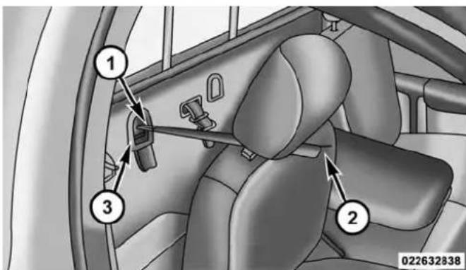
RegularCabTetherAnchorage
| 1 — Tether Strap Hook |
| 2 — Tether Strap to Child Restraint |
| 3 — Tether Anchor |
THINGS TO KNOW BEFORE STARTING YOUR VEHICLE 99
-
Route the tether strap to provide the most direct path between the anchorage and the child seat. The tether strap should go between the head restraint posts underneath the head restraint. You may need to adjust the head restraint to the upward position to pass the tether strap underneath the head restraint and between its posts.
-
Lift the cover (if so equipped), and attach the hook to the square opening in the sheet metal. Tighten the tether strap according to the child seat manufacturer's instructions.
100 THINGS TO KNOW BEFORE STARTING YOUR VEHICLE
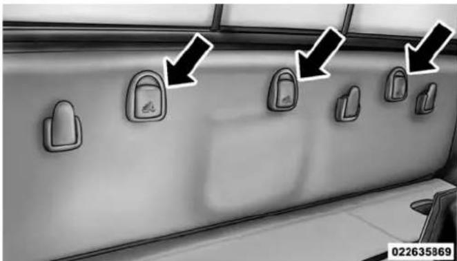
natural_image
Interior view of a car showing multiple car washers with directional arrows pointing to the door (no text or symbols on the covers)MegaCab®TetherAnchorage
WARNING!
Neverplacearear-facingchildrestraintinfrontofan airbag.AdeployingPassengerAdvancedFrontAir Bagcancausedeathorseriousinjurytoachild12
WARNING!(Continued)
yearsoryounger, includingachildinarear-facing childrestraint.
QuadCab®orCrewCabTrucks:
The top tether anchorages in this vehicle are tether strap loops located between the rear glass and the back of the rear seat. There is a tether strap loop located behind each seating position. Follow the steps below to attach the tether strap of the child restraint.
RightorLeftOutboardSeats:
- Raise the head restraint and reach between the rear seat and rear glass to access the tether strap loop.
(Continued)

natural_image
Interior view of a car showing the rear seat, frontrest, and backrest (no text or symbols visible)THINGS TO KNOW BEFORE STARTING YOUR VEHICLE 101
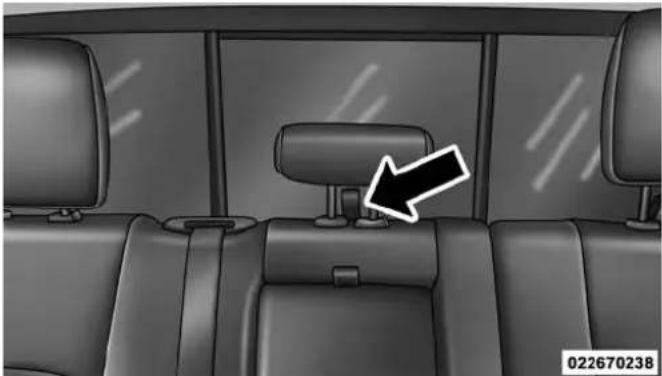
natural_image
Interior view of a car showing rear seats and seatbelt, with a black arrow pointing to the backrest (no text or symbols on the main body)HeadRestraintInRaisedPositionTetherStrapLoopWithCenterHeadRestraintIn
RaisedPosition
- Place a child restraint on the seat and adjust the tether strap so that it will reach over the seat back, under the head restraint, through the tether strap loop behind the seat and over to the tether strap loop behind the center seat.
102 THINGS TO KNOW BEFORE STARTING YOUR VEHICLE
- Pass the tether strap hook under the head restraint behind the child seat, though the tether strap loop behind the seat and over to the center tether strap loop.
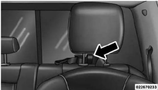
natural_image
Interior view of a car showing the rear seat, driver's seat, and dashboard (no text or symbols visible)TetherStrapThroughOutboardTetherStrapLoop
- Attach the hook to the center tether strap loop (see diagram). Tighten the tether strap according to the child seat manufacturer's instructions.

natural_image
Interior view of a car showing rear seats and seatbelt, with two black arrows pointing to the back seat (no text or symbols present)TetherStrapThroughOutboardTetherStrapLoopAnd AttachedToCenterTetherStrapLoop
NOTE: If there are child seats in both of the outboard (left and right) seating positions, the tether strap hooks of both child seats should be connected to the center tether strap loop. This is the correct way to tether two outboard child seats.
CenterSeat:
- Raise the head restraint and reach between the rear seat and rear glass to access the tether strap loop.
THINGS TO KNOW BEFORE STARTING YOUR VEHICLE 103

natural_image
Interior view of a car showing rear seats and seatbelt, with a black arrow pointing to the backrest (no text or symbols)TetherStrapLoopWithHeadRestraintInRaised Position
- Place a child restraint on the seat and adjust the tether strap so that it will reach over the seat back, under the head restraint, through the tether strap loop behind the seat and over to the tether strap loop behind either the right or left outboard seat.
104 THINGS TO KNOW BEFORE STARTING YOUR VEHICLE
- Pass the tether strap hook under the head restraint behind the child seat, though the tether strap loop behind the seat and over to the right or left outboard tether strap loop.

natural_image
Interior view of a car showing the rear seat, rear seats, and a backrest with a white arrow pointing to the seat (no text or symbols on the main body)TetherStrapThroughCenterTetherStrapLoop
- Attach the hook to the outboard tether strap loop (see diagram). Tighten the tether strap according to the child seat manufacturer's instructions.

natural_image
Interior view of a car showing rear seats and seatbelt, with two arrows pointing to the backrest (no text or symbols present)TetherStrapThroughCenterTetherStrapLoopAnd AttachedToOutboardTetherStrapLoop
InstallingThreeChildRestraints:
- Place a child restraint on each outboard rear seat. Route the tether straps following the directions for right and left seating positions, above.
- Attach both hooks to the center tether strap loop, but do not tighten the straps yet.
- Place a child restraint on the center rear seat. Route the tether strap following the directions for the center seating position, above.
- Attach the hook to the outboard tether strap loop.
- Tighten the tether straps according to the child seat manufacturer's instructions, tightening the right and left tether straps before the center tether strap.
THINGS TO KNOW BEFORE STARTING YOUR VEHICLE 105

natural_image
Interior view of a car showing three rear seats with white arrows pointing to the seat (no text or symbols)LeftOutboardAndCenterSeatingPositionShown
WARNING!
- Anincorrectlyanchoredtetherstrapcouldleadto increasedheadmotionandpossibleinjurytothe child.Useonlytheanchoragepositiondirectly behindthechildseattosecureachildrestrainttop tetherstrap.
- If your vehicle is equipped with a split reseat, makes sure the ether strap does not slip into the opening between these seats as you remove slack in the strap.
Transporting Pets
Air Bags deploying in the front seat could harm your pet. An unrestrained pet will be thrown about and possibly injured, or injure a passenger during panic braking or in a collision.
Pets should be restrained in the rear seat in pet harnesses or pet carriers that are secured by seat belts.
ENGINE BREAK-IN RECOMMENDATIONS
A long break-in period is not required for the engine and drivetrain (transmission and axle) in your vehicle.
Drive moderately during the first 300 miles (500 km). After the initial 60 miles (100 km), speeds up to 50 or 55 mph (80 or 90 km/h) are desirable.
While cruising, brief full-throttle acceleration within the limits of local traffic laws contributes to a good break-in. Wide-open throttle acceleration in low gear can be detrimental and should be avoided.
The engine oil installed in the engine at the factory is a high-quality energy conserving type lubricant. Oil changes should be consistent with anticipated climate conditions under which vehicle operations will occur. For the recommended viscosity and quality grades, refer to “Maintenance Procedures” in “Maintaining Your Vehicle.”
CAUTION!
NeveruseNon-DetergentOilorStraightMineralOil intheengineordamagemayresult.
NOTE:A new engine may consume some oil during its first few thousand miles (kilometers) of operation. This should be considered a normal part of the break-in and not interpreted as a problem.
Diesel Engine
The Cummins® turbocharged diesel engine does not require a break-in period due to its construction. Normal operation is allowed, providing the following recommendations are followed:
- Warm up the engine before placing it under load.
- Do not operate the engine at idle for prolonged periods.
THINGS TO KNOW BEFORE STARTING YOUR VEHICLE 107
- Use the appropriate transmission gear to prevent engine lugging.
- Observe vehicle oil pressure and temperature indicators.
- Check the coolant and oil levels frequently.
- Vary throttle position at highway speeds when carrying or towing significant weight.
NOTE: Light duty operation such as light trailer towing or no load operation will extend the time before the engine is at full efficiency. Reduced fuel economy and power may be seen at this time.
For additional vehicle break-in requirements, refer to "Trailer Towing" in "Starting and Operating" of the Owners Manual.
108 THINGS TO KNOW BEFORE STARTING YOUR VEHICLE
Because of the construction of the Cummins® turbo-charged diesel engine, engine run-in is enhanced by loaded operating conditions which allow the engine parts to achieve final finish and fit during the first 6,000 miles (10 000 km).
SAFETY TIPS
Transporting Passengers
NEVER TRANSPORT PASSENGERS IN THE CARGO AREA.
WARNING!
- Donotleavechildrenoranimalsinsideparked vehiclesinhotweather.Interiorheatbuild-upmay causeseriousinjuryordeath.
WARNING!(Continued)
- Itisextremelydangeroustorideinacargoarea, insideoroutsideofvehicle.Inacollision,people ridingintheseareasaremorelikelytobeseriously injuredorkilled.
- Donotallowpeopleorideinanyareaofyour vehiclethatisnotequippedwithseatsandseat belts.
- Besureeveryoneinyourvehicleisinaseatand usingaseatbeltproperly.
(Continued)
Exhaust Gas
WARNING!
Exhaustgasescaninjureorkill. They contain carbon monoxide(CO), which is colorless and odorless.
Breathingitcanmakeyouunconsciousandcan eventuallypoisonyou.Toavoidbreathing(CO), followthesesafetytips:
- Donotruntheengineinaclosedgarageorin confinedareasanylongerthanneededtomove yourvehicleinoroutofthearea.
- If you are required to drivewith the trunk/lift gate/reardors open, makes sure that all windows are closed and the climate control BLOWER switch this set at high speed. DONOT use there circulation mode.
(Continued)
THINGS TO KNOW BEFORE STARTING YOUR VEHICLE 109
WARNING!(Continued)
- Ifitisnecessarytositinaparkedvehiclewiththe engineerunning,adjustyourheatingorcooling controlstoforceoutsideairintothevehicle.Setthe blowerathighspeed.
The best protection against carbon monoxide entry into the vehicle body is a properly maintained engine exhaust system.
Whenever a change is noticed in the sound of the exhaust system, when exhaust fumes can be detected inside the vehicle, or when the underside or rear of the vehicle is damaged, have a competent mechanic inspect the complete exhaust system and adjacent body areas for broken, damaged, deteriorated, or mispositioned parts. Open seams or loose connections could permit exhaust fumes to seep into the passenger compartment. In addition, inspect the exhaust system each time the vehicle is raised for lubrication or oil change. Replace as required.
110 THINGS TO KNOW BEFORE STARTING YOUR VEHICLE
Safety Checks You Should Make Inside The Vehicle
SeatBelts
Inspect the seat belt system periodically, checking for cuts, frays, and loose parts. Damaged parts must be replaced immediately. Do not disassemble or modify the system.
Front seat belt assemblies must be replaced after a collision. Rear seat belt assemblies must be replaced after a collision if they have been damaged (i.e., bent retractor, torn webbing, etc.). If there is any question regarding seat belt or retractor condition, replace the seat belt.
AirBagWarningLight

The light should come on and remain on for four to eight seconds as a bulb check when the ignition switch is first turned ON. If the light is
not lit during starting, see your authorized dealer. If the light stays on, flickers, or comes on while driving, have the system checked by an authorized dealer.
Defroster
Check operation by selecting the defrost mode and place the blower control on high speed. You should be able to feel the air directed against the windshield. See your authorized dealer for service if your defroster is inoperable.
FloorMatSafetyInformation
Always use floor mats designed to fit the footwell of your vehicle. Use only floor mats that leave the pedal area unobstructed and that are firmly secured so that they cannot slip out of position and interfere with the pedals or impair safe operation of your vehicle in other ways.
THINGS TO KNOW BEFORE STARTING YOUR VEHICLE 111
WARNING!
Pedalsthatcannotmovefreelycancauselossof vehiclecontrolandincreasetheriskofseriouspersonalinjury.
- Alwaysmakesurethatfloormatsareproperly attachedtothefloormatfasteners.
- Neverplaceorinstallfloormatsorotherfloor coveringsinthevehiclethatcannotbeproperly securedtopreventthemfrommovingandinterferingwiththepedalsortheabilitytocontrolthe vehicle.
- Neverputfloormatsorotherfloorcoveringsontop ofalreadyinstalledfloormats.Additionalfloor matsandothercoveringswillreducethesizeofthe pedalareaandinterferewiththepedals.
WARNING!(Continued)
- Checkmountingofmatsonaregularbasis.Always properlyreinstallandsecurefloormatsthathave beenremovedforcleaning.
- Alwaysmakesurethatobjectscannotfallintothe driverfootwellwhilethevehicleismoving.Objectscanbecometrappedunderthebrakepedal andacceleratorpedalcausingalossofvehicle control.
- If required, mountingpostsmustbeproperlyinstalled, if notequipped from the factory. Failuretoproperlyfollowfloormatinstallation or mountingcan cause interference with the brake pedalandaccelerator pedal operation causing loss of control of the vehicle.
(Continued)
112 THINGS TO KNOW BEFORE STARTING YOUR VEHICLE
Periodic Safety Checks You Should Make Outside The Vehicle
Tires
Examine tires for excessive tread wear and uneven wear patterns. Check for stones, nails, glass, or other objects lodged in the tread or sidewall. Inspect the tread for cuts and cracks. Inspect sidewalls for cuts, cracks, and bulges. Check the wheel bolts for tightness. Check the tires (including spare) for proper cold inflation pressure.
Lights
Have someone observe the operation of brake lights and exterior lights while you work the controls. Check turn signal and high beam indicator lights on the instrument panel.
DoorLatches
Check for positive closing, latching, and locking.
FluidLeaks
Check area under vehicle after overnight parking for fuel, engine coolant, oil, or other fluid leaks. Also, if gasoline fumes are detected or if fuel, power steering fluid (if equipped), or brake fluid leaks are suspected. The cause should be located and corrected immediately.
UNDERSTANDING THE FEATURES OF YOUR VEHICLE
CONTENTS
■MIRRORS....1 1 7
□Inside Day/Night Mirror — If Equipped . . . . . 1 1 7
□Automatic Dimming Mirror — If Equipped . . .118
□Automatic Dimming Mirror With Rear View Camera Display — If Equipped . . . . . . . . . . . .124
□Outside Mirrors....125
□ Outside Mirrors Folding Feature .....125
□Power Mirrors — If Equipped .....126
□Heated Mirrors — If Equipped . . . . . . . . . . . . .128
□Illuminated Vanity Mirror — If Equipped . . . .128
□“Slide-On-Rod” Features Of Sun Visor —
If Equipped....128
□ Trailer Towing Mirrors — If Equipped .....129
■ SEATS ....130
□ Driver's Power Seat — If Equipped .....131
□ Passenger's Power Seat — If Equipped .....133
□Power Lumbar — If Equipped .....134
□ Heated Seats — If Equipped....134
□ Ventilated Seats — If Equipped....137
□ Manual Seat Adjuster — If Equipped. . . . . . . .138
114 UNDERSTANDING THE FEATURES OF YOUR VEHICLE
□40-20-40 Front Bench Seat — If Equipped . . . .139
□Head Restraints....139
■DRIVER MEMORY SEAT — IF EQUIPPED . . .143
□Programming The Memory Feature .....144
□Linking And Unlinking The Remote Keyless Entry Transmitter To Memory . . . . . . . . . . . . . . . . . . . . . . . . . . . . . . . . . . . . . . . . . . . . . . . . . . . . . . . . . . . . . . . . .
□Memory Position Recall....146
□Easy Entry/Exit Seat....147
■TO OPEN AND CLOSE THE HOOD .....148
■LIGHTS....149
□Headlights....151
□Automatic Headlights — If Equipped . . . . . . .151
□Headlights On With Wipers (Available With Automatic Headlights Only)....152
□Daytime Running Lights (DRL) — If Equipped . . . . . . . . . . . . . . . . . . . . . . . . . . . . . . . . . . . . . . . . . . . . . . . . . . . . . . . . . . . . . . . . . 152
□Headlight Delay....152
□Automatic High Beam Headlamp Control — If Equipped .....153
□Parking Lights And Panel Lights. . . . . . . . . . . . . . . . . . . . . . . . . . . . . . . . . . . . . . . . . . . . . . . . . . . . . . . . . . . .
□Fog Lights — If Equipped . . . . . . . . . . . . . . . . . . . . . . . . . . . . . . . . . . . . . . . . . . . . . . . . . . . . . . . . . . . 155
□Lights-On Reminder....156
□Battery Saver. . . . . . . . . . . . . . . . . . . . . . . . . . . . . . . . . . . . . . . . . . . . . . . . . . . . . . . . . 156
□Interior Lights....157
□Cargo Light....160
□Multifunction Lever....160
□Turn Signals....160
□Lane Change Assist ....161
□Flash-To-Pass....161
□High/Low Beam Switch....162
■WINDSHIELD WIPERS AND WASHERS .....162
□Windshield Wipers....162
□Windshield Wiper Operation....163
□Intermittent Wiper System....163
□Windshield Washers....163
□Mist Feature....164
□Rain Sensing Wipers — If Equipped . . . . . . . .164
■TILT STEERING COLUMN....166
■DRIVER ADJUSTABLE PEDALS — IF EQUIPPED....167
■HEATED STEERING WHEEL — IF EQUIPPED....168
UNDERSTANDING THE FEATURES OF YOUR VEHICLE 115
■ELECTRONIC SPEED CONTROL....170
□To Activate....171
□To Set A Desired Speed....171
□To Deactivate....172
□To Resume Speed....172
□To Vary The Speed Setting .....172
□To Accelerate For Passing....173
■OVERHEAD CONSOLE — IF EQUIPPED . . . . .174
□Courtesy/Reading Lights....175
■ELECTRICAL POWER OUTLETS....176
■AUXILIARY SWITCHES — IF EQUIPPED . . . . .181
CIGAR LIGHTER AND ASH RECEIVER — IF EQUIPPED....182
116 UNDERSTANDING THE FEATURES OF YOUR VEHICLE
■POWER INVERTER — IF EQUIPPED .....183
■CUPHOLDERS....184
□Front Seat Cupholders (40–20–40 Seats) . . . . . .184
□Front Instrument Panel Cupholders — Floor Storage Bin. . . . . . . . . . . . . . . . . . . . . . . . . . . . . . . . . . . . . . . . . . . . . . . . . . . . . . . . . . 184
□Rear Cupholders — If Equipped . . . . . . . . . . . . .185
■STORAGE....186
□Glove Compartment....186
□Door Storage....188
□ Center Storage Compartment — If Equipped . . .189
□Seatback Storage....191
□Storage (Regular Cab)....191
□Storage and Seats (Crew Cab)....192
□Plastic Grocery Bag Retainers (Regular Cab Models)....193
■REAR WINDOW FEATURES....193
□Rear Window Defroster....193
□Power Sliding Rear Window — If Equipped ..194
□Manual Sliding Rear Window — If Equipped .....194
UNDERSTANDING THE FEATURES OF YOUR VEHICLE 117
MIRRORS
Inside Day/Night Mirror — If Equipped
A single ball joint mirror is provided in the vehicle. It is a twist on mirror that has a fixed position at the windshield. The mirror installs on the windshield button with a counterclockwise rotation and requires no tools for mounting. The mirror head can be adjusted up, down, left, and right for various drivers. The mirror should be adjusted to center on the view through the rear window.
Headlight glare from vehicles behind you can be reduced by moving the small control under the mirror to the night position (toward the rear of the vehicle). The mirror should be adjusted while the small control under the mirror is set in the day position (toward the windshield).

natural_image
Top-down view of a car rearview mirror with a black arrow pointing to the side (no text or symbols on the mirror itself)AdjustingRearviewMirror
118 UNDERSTANDING THE FEATURES OF YOUR VEHICLE
Automatic Dimming Mirror — If Equipped
A single ball joint mirror is provided in the vehicle. It is a twist on mirror that has a fixed position at the windshield. The mirror installs on the windshield button with a counterclockwise rotation and requires no tools for mounting. The mirror head can be adjusted up, down, left, and right for various drivers. The mirror should be adjusted to center on the view through the rear window.
This mirror automatically adjusts for headlight glare from vehicles behind you.
NOTE: The Automatic Dimming Mirror feature is disabled when the vehicle is in reverse gear to improve rear view viewing.
The Automatic Dimming Mirror feature can be turned On or Off through the touchscreen.
- Press the Mirror Dimmer button once to turn the feature On.
- Press the Mirror Dimmer button a second time to turn the feature Off.

natural_image
Front view of a car rearview mirror with no visible text or symbols on the surface0304049205
AutomaticDimmingMirror
If equipped, the rearview mirror contains an ASSIST and a 9-1-1 button.
NOTE:The ASSIST and 9-1-1 features operate through the Uconnect® Access service. These buttons will only operate as long as your Uconnect® Access service is active. Refer to your "Uconnect® System supplement manual" for further information.
ASSISTCall
The ASSIST Button is used to automatically connect you to any one of the following support centers:
- Roadside Assistance – If you get a flat tire, or need a tow, just press the Assist button and you'll be connected to someone who can help. Roadside Assistance will know what vehicle you're driving and its location. Additional fees may apply for roadside Assistance.
- Uconnect® Access Customer Care – In-vehicle support for Uconnect® Access and Uconnect® Access Via Mobile features.
UNDERSTANDING THE FEATURES OF YOUR VEHICLE 119
- Vehicle Customer Care – Total support for all other vehicle issues.
9-1-1Call
- Press the 9-1-1 Call button on the Rearview Mirror.
NOTE: In case the 9-1-1 Call button is pushed in error, there will be a 10 second delay before the 9-1-1 Call system initiates a call to a 9-1-1 operator. To cancel the 9-1-1 Call connection, press the 9-1-1 Call button on the Rearview Mirror or press the cancellation button on the Phone Screen. Termination of the 9-1-1 Call will turn the green LED light on the Rearview Mirror off. - The LED light located between the Assist and 9-1-1 buttons on the Rearview Mirror will turn green once a connection to a 9-1-1 operator has been made.
120 UNDERSTANDING THE FEATURES OF YOUR VEHICLE
- Once a connection between the vehicle and a 9-1-1 operator is made, the 9-1-1 Call system may transmit the following important vehicle information to a 9-1-1 operator:
- Indication that the occupant placed a 9-1-1 Call.
• The vehicle brand.
- The last known GPS coordinates of the vehicle.
- You should be able to speak with the 9-1-1 operator through the vehicle audio system to determine if additional help is needed.
NOTE: Once a connection is made between the vehicle's 9-1-1 Call system and the 9-1-1 operator, the 9-1-1 operator may be able to open a voice connection with the vehicle to determine if additional help is needed. Once the 9-1-1 operator opens a voice connection with the vehicle's 9-1-1 Call system, the operator should be able to speak with you or other vehicle occupants and hear sounds occurring in the vehicle. The vehicle's 9-1-1 Call system will attempt to remain connected with the 9-1-1 operator until the 9-1-1 operator terminates the connection.
- The 9-1-1 operator may attempt to contact appropriate emergency responders and provide them with important vehicle information and GPS coordinates.
UNDERSTANDING THE FEATURES OF YOUR VEHICLE 121
WARNING!
- Ifanyoneinthevehiclecouldbeindanger(e.g., fireorsmokeisvisible,dangerousroadconditions orlocation),donotwaitforvoicecontactfroma 9-1-1operator.Alloccupantsshouldexitthevehicle immediatelyandmovetoasafelocation.
(Continued)
WARNING!(Continued)
- The9-1-1Callsystemisembeddedintothevehicle'selectricalsystem.Donotaddaftermarket electricalequipmenttothevehicle'selectricalsystem.Thismaypreventyourvehiclefromsendinga signaltoinitiateanemergencycall.Toavoidinterferencethatcancausethe9-1-1Callsystemtofail, neveraddaftermarketequipment(e.g.,two-way mobileradio,CBradio,datarecorder,etc.)toyour vehicle'selectricalsystemormodifytheantennas onyourvehicle.IFYOURVEHICLELOSESBATTERYPOWERFORANYREASON(INCLUDING DURINGOR AFTERANACCIDENT),THE UCONNECTFEATURES,APPSANDSERVICES, AMONGOTHERS,WILLNOTOPERATE.
(Continued)
122 UNDERSTANDING THE FEATURES OF YOUR VEHICLE
WARNING!(Continued)
- Modificationstoanypartofthe9-1-1Callsystem couldcausetheairbagsystemtofailwhenyou needit.Youcouldbeinjurediftheairbagsystem isnottheretohelpprotectyou.
9-1-1CallSystemLimitations
Vehicles sold in Canada and Mexico DO NOT have 9-1-1 Call system capabilities.
9-1-1 or other emergency line operators in Canada and Mexico may not answer or respond to 9-1-1 system calls.
If the 9-1-1 Call system detects a malfunction, any of the following may occur at the time the malfunction is detected, and at the beginning of each ignition cycle:
- The Rearview Mirror light located between the Assist and 9-1-1 buttons will continuously be illuminated red.
- The Phone Screen will display the following message "Vehicle phone requires service. Please contact your dealer."
- An In-Vehicle Audio message will state "Vehicle phone requires service. Please contact your dealer."
WARNING!
- IgnoringtheRearviewMirrorlightcouldmeanyou willnothave9-1-1Callservices.IftheRearview Mirrorlightisilluminated,haveanaauthorized dealerservicethe9-1-1Callsystemimmediately.
(Continued)
WARNING!(Continued)
- TheOccupantRestraintControlmoduleturnson theAirBagWarningLightontheinstrumentpanel ifamalfunctioninanypartofthesystemis detected. IftheAirBagWarningLightisilluminated, theairbagsystemmaynotbeworking properly and the9-1-1systemmaynotbeableto sendasignaltoa9-1-1operator. IftheAirBag WarningLightisilluminated, haveanauthorized dealerservicetheORCsystemimmediately.
Even if the 9-1-1 Call system is fully functional, factors beyond Chrysler Group LLC's control may prevent or stop the 9-1-1 Call system operation. These include, but are not limited to, the following factors:
- Delayed accessories mode is active.
• The ignition is in the OFF position.
UNDERSTANDING THE FEATURES OF YOUR VEHICLE 123
- The vehicle's electrical systems are not intact.
- The 9-1-1 Call system software and/or hardware are damaged during a crash.
- The vehicle battery loses power or becomes disconnected during a vehicle crash.
- Wireless and/or Global Positioning Satellite signals are unavailable or obstructed.
• Equipment malfunction at the 9-1-1 operator facility. - Operator error by the 9-1-1 operator.
- Wireless network congestion.
- Weather.
• Buildings, structures, geographic terrain, or tunnels.
124 UNDERSTANDING THE FEATURES OF YOUR VEHICLE
NOTE: Never place anything on or near the vehicle's wireless and GPS antennas. You could prevent wireless and GPS signal reception, which can prevent your vehicle from placing an emergency call. Wireless and GPS signal reception is required for the 9-1-1 Call system to function properly.
GeneralInformation
This device complies with Part 15 of the FCC Rules. Operation is subject to the following two conditions: (1) This device may not cause harmful interference, and (2) this device must accept any interference received, including interference that may cause undesired operation.
CAUTION!
Toavoiddamagetothemirrorduringcleaning, never sprayanycleaningsolutiondirectlyontothemirror. Applythesolutionontoacleanclothandwipethe mirrorclean.
Automatic Dimming Mirror With Rear View Camera Display — If Equipped
A single ball joint mirror is provided in the vehicle. It is a twist on mirror that has a fixed position at the windshield. The mirror installs on the windshield button with a counterclockwise rotation and requires no tools for mounting. The mirror head can be adjusted up, down, left, and right for various drivers. The mirror should be adjusted to center on the view through the rear window.
This mirror automatically adjusts for headlight glare from vehicles behind you.
UNDERSTANDING THE FEATURES OF YOUR VEHICLE 125
When the vehicle is placed into reverse gear a video display illuminates to display the image generated by the rear view camera. The auto dimming feature is also disabled to improve rear view viewing.
Outside Mirrors
To receive maximum benefit, adjust the outside mirrors to center on the adjacent lane of traffic with a slight overlap of the view obtained on the inside mirror.
NOTE: If your vehicle is equipped with illuminated approach lights under the outside mirrors they can be turned off through the instrument cluster or the Uconnect® radio. For further information refer to "EVIC" or "DID" and "Uconnect® Settings" in "Understanding Your Instrument Panel".
WARNING!
Vehiclesandotherobjectsseeninthepassengerside convexmirrorwilllooksmallerandfartheraway thantheyreallyare.Relyingtoomuchonyour passengersideconvexmirrorcouldcauseyouto collidewithanothervehicleorotherobject.Useyour insidemirrorwhenjudgingthesizeordistanceofa vehicleseeninthepassengersideconvexmirror. Somevehicleswillnothaveaconvexpassengerside mirror.
Outside Mirrors Folding Feature
All outside mirrors are designed to be able to be manually folded both forward and rearward to prevent damage.
126 UNDERSTANDING THE FEATURES OF YOUR VEHICLE
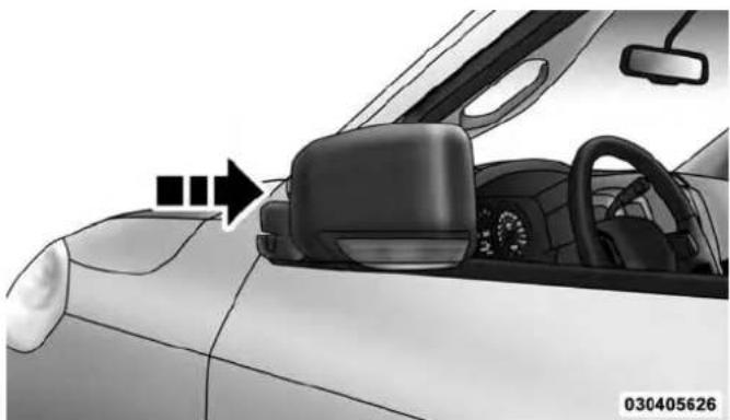
natural_image
Interior view of a car showing the dashboard, steering wheel, and side mirror (no text or symbols visible)FoldingMirror
CAUTION!
Itisrecommendedtofoldthemirrorsintothefull rearwardpositiontoresistdamagewhenenteringa carwashoranarrowlocation.
Power Mirrors — If Equipped
The controls for the power mirrors are located on the driver's door trim panel.

natural_image
Interior view of a car dashboard with a control panel and directional arrow (no text or symbols)PowerMirrorControlsLocation
The power mirror controls consist of mirror select buttons and a four-way mirror control switch.

PowerMirrorControls
1 — Mirror Select Buttons
2 — Four-Way Mirror Control Switch
To adjust a mirror, press either the L (left) or R (right) button to select the mirror that you want to adjust.
UNDERSTANDING THE FEATURES OF YOUR VEHICLE 127
Using the mirror control switch, press on any of the four arrows for the direction that you want the mirror to move.

natural_image
Side view of a car's front and dashboard showing a directional sign with cross symbol (no text or labels)PowerMirrorMovement
128 UNDERSTANDING THE FEATURES OF YOUR VEHICLE Heated Mirrors — If Equipped
These mirrors are heated to melt frost or ice. This feature can be activated whenever you turn on the rear window defroster (if equipped). Refer to "Rear Window Features" in "Understanding The Features Of Your Vehicle" for further information.
Illuminated Vanity Mirror — If Equipped
Illuminated vanity mirrors are located on each sun visor. To use the mirror, rotate the sun visor down and swing the mirror cover upward. The lights will turn on automatically. Closing the mirror cover turns off the light.
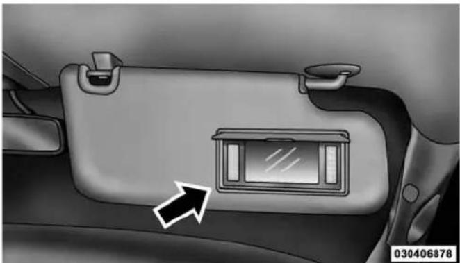
natural_image
Interior view of a car showing the backrest door and side panel with an arrow pointing to it (no text or symbols)Illuminated VanityMirror
"Slide-On-Rod" Features Of Sun Visor — If Equipped
The sun visor "Slide-On-Rod" feature allows for additional flexibility in positioning the visor to block out the sun.
To use the "Slide-On-Rod" feature, rotate the sun visor downward and unclip it. Pull the sun visor along the "Slide-On-Rod" until the sun visor is in the desired position.
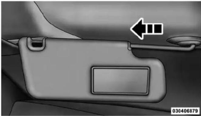
natural_image
Interior view of a car's rear seatbelt with a directional arrow and label (no text or symbols on the main subject)"Slide-On-Rod"Extender
UNDERSTANDING THE FEATURES OF YOUR VEHICLE 129
Trailer Towing Mirrors — If Equipped
These mirrors are designed with an adjustable mirror head to provide a greater vision range when towing extra-wide loads. To change position inboard or outboard, the mirror head should be rotated (flipped in or out).

natural_image
Close-up of a car's side mirror and dashboard, showing a black arrow pointing to the side mirror (no text or symbols on the main components)TrailerTowingPosition
130 UNDERSTANDING THE FEATURES OF YOUR VEHICLE
NOTE: Fold the trailer towing mirrors rearward prior to entering an automated car wash.
A small blindspot mirror is located next to main mirror and can be adjusted separately.
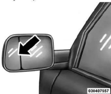
natural_image
Close-up of a car's side mirror showing a black arrow pointing downward (no text or symbols)BlindspotMirror
SEATS
Seats are a part of the Occupant Restraint System of the vehicle.
WARNING!
- Itisdangeroustorideinacargoarea,insideor outsideofavehicle.Inacollision,peopleridingin theseareasaremorelikelytobeseriouslyinjured orkilled.
- Donotallowpeopletorideinanyareaofyour vehiclethatisnotequippedwithseatsandseat belts.Inacollision,peopleridingintheseareasare morelikelytobeseriouslyinjuredorkilled.
- Besureeveryoneinyourvehicleisinaseatand usingaseatbeltproperly.
UNDERSTANDING THE FEATURES OF YOUR VEHICLE 131
Driver's Power Seat — If Equipped
Some models may be equipped with an eight-way power driver's seat. The power seat switches are located on the outboard side of the driver's seat cushion. There are two power seat switches that are used to control the movement of the seat cushion and the seatback.
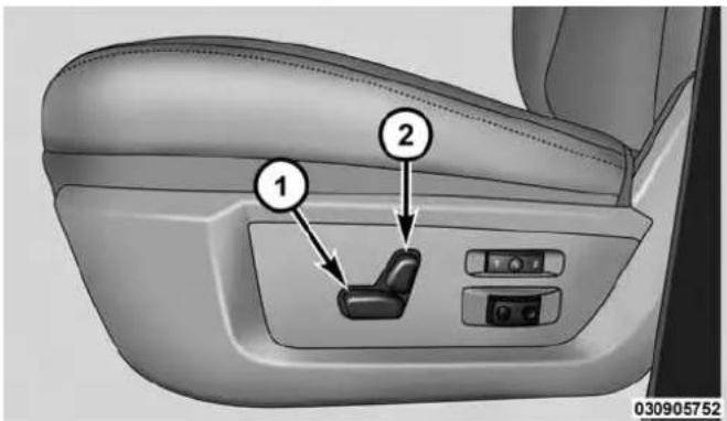
PowerSeatSwitches
1 — Power Seat Switch
2 — Power Seatback Switch
132 UNDERSTANDING THE FEATURES OF YOUR VEHICLE
AdjustingTheSeatForwardOrRearward
The seat can be adjusted both forward and rearward. Push the seat switch forward or rearward, the seat will move in the direction of the switch. Release the switch when the desired position has been reached.
AdjustingTheSeatUpUpDown
The height of the seats can be adjusted up or down. Pull upward or push downward on the seat switch, the seat will move in the direction of the switch. Release the switch when the desired position is reached.
RecliningTheSeatback
The angle of the seatback can be adjusted forward or rearward. Push the seatback switch forward or rearward, the seat will move in the direction of the switch. Release the switch when the desired position is reached.
WARNING!
- Adjustingaseatwhiledrivingmaybedangerous. Movingaseatwhiledrivingcouldresultinlossof controlwhichcouldcauseacollisionandserious injuryordeath.
- Seatsshouldbeadjustedbeforefasteningtheseat beltsandwhilethevehicleisparked.Serious injuryordeathcouldresultfromapoorlyadjusted seatbelt.
- Donotridewiththeseatbackreclinedsothatthe shoulderbeltisnolongerrestingagainstyour chest.Inacollisionyoucouldslideundertheseat belt,whichcouldresultinseriousinjuryordeath.
CAUTION!
Donotplaceanyarticleunderapowerseator impedeitsabilitytomoveasitmaycausedamageto theseatcontrols.Seattravelmaybecomelimitedif movementisstoppedbyanobstructionintheseat's path.
TiltingTheSeatUpUpDown
The angle of the seat cushion can be adjusted in four directions. Pull upward or push downward on the front or rear of the seat switch, the front or rear of the seat cushion will move in the direction of the switch. Release the switch when the desired position is reached.
Passenger's Power Seat — If Equipped
Some models are equipped with a six-way power passenger seat. The power seat switch is located on the
UNDERSTANDING THE FEATURES OF YOUR VEHICLE 133
outboard side of the seat. The switch is used to control the movement of the seat and seat cushion.
AdjustingTheSeatForwardOrRearward
The seat can be adjusted both forward and rearward. Push the seat switch forward or rearward, the seat will move in the direction of the switch. Release the switch when the desired position has been reached.
AdjustingTheSeatUpUpDown
The height of the seats can be adjusted up or down. Pull upward or push downward on the seat switch, the seat will move in the direction of the switch. Release the switch when the desired position is reached.
TiltingTheSeatUpUpDown
The angle of the seat cushion can be adjusted up or down. Pull upward or push downward on the front of
134 UNDERSTANDING THE FEATURES OF YOUR VEHICLE
the seat switch, the front of the seat cushion will move in the direction of the switch. Release the switch when you have reached the desired position.
Power Lumbar — If Equipped
Vehicles equipped with power driver or passenger seats may be also be equipped with power lumbar. The power lumbar switch is located on the outboard side of the power seat. Push the switch forward to increase the lumbar support. Push the switch rearward to decrease the lumbar support.
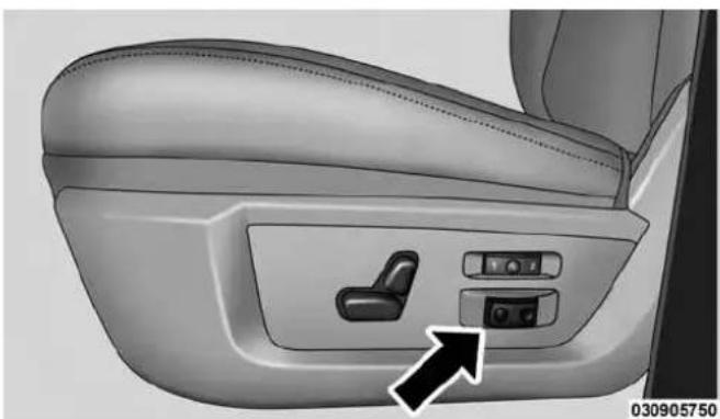
natural_image
Interior view of a car seat with a control panel and directional arrow (no text or symbols)LumbarControlSwitch
Heated Seats — If Equipped
On some models, the front and rear seats may be equipped with heaters located in the seat cushions and seat backs.
UNDERSTANDING THE FEATURES OF YOUR VEHICLE 135
WARNING!
- Persons who are unable to feel in the skin because of advanced age, chronic illness, diabetes, spinal cord injury, medication, alcohol use, exhaustion or other physical condition must exercise care when using these at least a theater. It may cause burns even at low temperatures, especially if used for long period so time.
- Donotplaceanythingontheseatorseatbackthat insulatesagainstheat,suchasablanketorcushion. Thismaycausetheseatheatertooverheat.Sitting inaseatthathasbeenoverheatedcouldcause seriousburnsduetotheincreasedsurfacetemperatureoftheseat.
FrontHeatedSeats
The front heated seats control buttons are located within the climate or controls screen of the touchscreen.
- Press the heated seat button setting On.
# once to turn the High
- Press the heated seat button the Low setting On.
# a second time to turn
- Press the heated seat button the heating elements Off.
a third time to turn
If the HI-level setting is selected, the system will automatically switch to LO-level after approximately 60 minutes of continuous operation. At that time, the display will change from HI to LO, indicating the change. The LO-level setting will turn OFF automatically after approximately 45 minutes.
NOTE: The engine must be running for the heated seats to operate.
136 UNDERSTANDING THE FEATURES OF YOUR VEHICLE
VehiclesEquippedWithRemoteStart
On models that are equipped with remote start, the heated seats can be programmed to come on during a remote start.
If your vehicle is equipped with a touchscreen, this feature can be programmed through the Uconnect® system. Refer to "Uconnect® Settings" in "Understanding Your Instrument Panel" for further information.
RearHeatedSeats
On some models, the two outboard seats are equipped with heated seats. The heated seat switches for these seats are located on the rear of the center console.
There are two heated seat switches that allow the rear passengers to operate the seats independently. You can choose from HIGH, LOW or OFF heat settings. Amber indicator lights in each switch indicate the level of heat in use. Two indicator lights will illuminate for HIGH, one for LOW and none for OFF.

Press the switch once to select HIGH-level heating. Press the switch a second time to select LOW-level heating. Press the switch a third time to shut the heating elements OFF.
NOTE:
- Once a heat setting is selected, heat will be felt within two to five minutes.
- The engine must be running for the heated seats to operate.
When the HIGH-level setting is selected, the heater will provide a boosted heat level during the first four minutes of operation. Then, the heat output will drop to the normal HIGH-level. If the HIGH-level setting is selected,
the system will automatically switch to LOW-level after approximately 60 minutes of continuous operation. At that time, the number of illuminated LEDs changes from two to one, indicating the change. The LOW-level setting will turn OFF automatically after approximately 45 minutes.
Ventilated Seats — If Equipped
Located in the seat cushion are small fans that draw the air from the passenger compartment and pull air through fine perforations in the seat cover to help keep the driver and front passenger cooler in higher ambient temperatures. The fans operate at two speeds, HIGH and LOW.
The front ventilated seats control buttons are located within the climate or controls screen of the touchscreen.
- Press the ventilated seat button HIGH.
* once to choose
UNDERSTANDING THE FEATURES OF YOUR VEHICLE 137
- Press the ventilated seat button choose LOW.
- Press the ventilated seat button turn the ventilated seat OFF.
* a second time to
* a third time to
NOTE: The engine must be running for the ventilated seats to operate.
VehiclesEquippedWithRemoteStart
On models that are equipped with remote start, the ventilated seats can be programmed to come on during a remote start.
If your vehicle is equipped with a touchscreen, this feature can be programmed through the Uconnect® system. Refer to "Uconnect® Settings" in "Understanding Your Instrument Panel" for further information.
138 UNDERSTANDING THE FEATURES OF YOUR VEHICLE
Manual Seat Adjuster — If Equipped
Both front seats are adjustable forward or rearward. The manual seat adjustment handle is located under the seat cushion at the front edge of each seat.

natural_image
Close-up of a car's side panel showing the wheel and seatbelt, with a white arrow pointing to the left side (no text or symbols on the main subject)ManualSeatAdjuster
While sitting in the seat, pull up on the handle and slide the seat forward or backward. Release the bar once you have reached the desired position. Then, using body pressure, move forward and rearward on the seat to be sure that the seat adjusters have latched.
WARNING!
- Adjustingaseatwhiledrivingmaybedangerous. Movingaseatwhiledrivingcouldresultinlossof controlwhichcouldcauseacollisionandserious injuryordeath.
- Seatsshouldbeadjustedbeforefasteningtheseat beltsandwhilethevehicleisparked.Serious injuryordeathcouldresultfromapoorlyadjusted seatbelt.
RecliningRearSeats—IfEquipped
The recliner handle is located on the outside of the seat cushion. To adjust the seatback, lift upward on the handle, lean back on the seatback and when you reach the desired position, release the handle.

natural_image
Interior view of a car seatbelt with a black arrow pointing to the seat area (no text or symbols visible)RearSeatReclinerHandle
WARNING!
Donotridewiththeseatbackreclinedsothatthe shoulderbeltisnolongerrestingagainstyourchest. Inacollisionyoucouldslideundertheseatbelt, whichcouldresultinseriousinjuryordeath.
UNDERSTANDING THE FEATURES OF YOUR VEHICLE 139
40-20-40 Front Bench Seat — If Equipped
The seat is divided into three segments. The outboard seat portions are each 40% of the total width of the seat. On some models the back of the center portion (20%) easily folds down to provide an armrest/center storage compartment.
Head Restraints
Head restraints are designed to reduce the risk of injury by restricting head movement in the event of a rear impact. Head restraints should be adjusted so that the top of the head restraint is located above the top of your ear.
WARNING!
Theheadrestraintsforalloccupantsmustbeproperlyinstalledandadjustedpriortooperatingthe vehicleoroccupyingaseat.Headrestraintsshould
(Continued)
140 UNDERSTANDING THE FEATURES OF YOUR VEHICLE
WARNING!(Continued)
neverbeadjustedwhilethevehicleisinmotion. Drivingvehiclewiththeheadrestraintsimproperly adjustedorremovedcouldcauseseriousinjuryor deathintheeventofacollision.
FrontHeadRestraints
To raise the head restraint, pull upward on the head restraint. To lower the head restraint, press the adjustment button, located on the base of the head restraint, and push downward on the head restraint.
To remove the head restraint, raise it as far as it can go then press the release buttons at the base of each post while pulling the head restraint up. To reinstall the head restraint, put the head restraint posts into the holes while pressing the release buttons. Then adjust it to the appropriate height.
WARNING!
Alooseheadrestraintthrownforwardinacollision orhardstopcouldcauseseriousinjuryordeathto occupantsofthevehicle.Alwayssecurelystowremovedheadrestraintsinalocationoutsidetheoccupantcompartment.

natural_image
Mechanical assembly diagram showing two base legs with a black arrow pointing to a component (no text or symbols)AdjustmentButton
WARNING!
ALLtheheadrestraintsMUSTbereinstalledinthe vehicletoproperlyprotecttheoccupants.Followthe re-installationinstructionsabovepriortooperating thevehicleoroccupyingaseat.
UNDERSTANDING THE FEATURES OF YOUR VEHICLE 141
RearHeadRestraints
The rear seats are equipped with adjustable and removable head restraints. To raise the head restraint, pull upward on the head restraint. To lower the head restraint, press the adjustment buttons, located on the base of the head restraint, and push downward on the head restraint. To remove the head restraint, press the adjustment buttons while pulling upward on the whole assembly and raise it as far as it can go. To reinstall the headrest, put the headrest posts into the holes while pressing the adjustment buttons. Then adjust it to the appropriate height.
NOTE: To remove outboard restraints, the rear seat bottom must be folded up.
142 UNDERSTANDING THE FEATURES OF YOUR VEHICLE
WARNING!
Alooseheadrestraintthrownforwardinacollision orhardstopcouldcauseseriousinjuryordeathto occupantsofthevehicle.Alwayssecurelystowremovedheadrestraintsinalocationoutsidetheoccupantcompartment.

natural_image
Mechanical assembly diagram showing two metal components with a black arrow pointing to a specific part (no text or symbols present)AdjustmentButton
NOTE:The rear center head restraint (Crew Cab and Quad Cab) has only one adjustment position that is used to aid in the routing of a tether. Refer to "Occupant Restraints" in "Things to Know Before Starting Your Vehicle" for further information.
WARNING!
ALLtheheadrestraintsMUSTbereinstalledinthe vehicletoproperlyprotecttheoccupants.Followthe re-installationinstructionsabovepriortooperating thevehicleoroccupyingaseat.
DRIVER MEMORY SEAT — IF EQUIPPED
This feature allows the driver to store up to two different memory profiles for easy recall through a memory switch. Each memory profile contains desired position settings for the driver seat, side mirrors, adjustable pedals (if equipped) and a set of desired radio station presets. Your Remote Keyless Entry (RKE) transmitter can also be programmed to recall the same positions when the UNLOCK button is pressed.
UNDERSTANDING THE FEATURES OF YOUR VEHICLE 143
NOTE: Your vehicle is equipped with two RKE transmitters, one RKE transmitter can be linked to memory position 1 and the other transmitter can be linked to memory position 2.
The memory seat buttons are located on the outboard side of the drivers seat cushion.

natural_image
Interior view of a car seat with a black arrow pointing to the side panel (no text or symbols visible)MemorySeatButtons
144 UNDERSTANDING THE FEATURES OF YOUR VEHICLE Programming The Memory Feature
NOTE: To create a new memory profile, perform the following:
- Cycle the vehicles ignition to the ON/RUN position (do not start the engine).
- Adjust all memory profile settings to desired preferences (seat, side mirrors, adjustable pedals and radio station presets).
- Press and release the S (Set) button on the memory switch.
- Within five seconds, press and release either of the memory buttons (1) or (2). The Electronic Vehicle Information Center (EVIC) or Driver Information Display (DID) will display which memory position has been set.
NOTE:
- Memory profiles can be set without the vehicle in PARK, but the vehicle must be in PARK to recall a memory profile.
- To set a memory profile to your RKE transmitter, refer to "Linking And Unlinking The Remote Keyless Entry Transmitter To Memory" in this section.
Linking And Unlinking The Remote Keyless Entry Transmitter To Memory
Your RKE transmitters can be programmed to recall one of two pre-programmed memory profiles by pressing the UNLOCK button on the RKE transmitter.
NOTE: Before programming your RKE transmitters to memory the feature has to be selected.
- If your vehicle is equipped with a touchscreen, you must select the "Memory To FOB" feature through the
Uconnect® system. Refer to "Uconnect® Settings" in "Understanding Your Instrument Panel" for further information.
- If your vehicle is not equipped with a touchscreen, you must select the "Key Fob Linked To Memory" feature through the Electronic Vehicle Information Center (EVIC) or Driver Information Display (DID). Refer to "Electronic Vehicle Information Center (EVIC)" or "Driver Information Display (DID)" in "Understanding Your Instrument Panel" for further information.
To program your RKE transmitters, perform the following:
- Cycle the vehicles ignition to the Off position.
- Select desired memory profile (1) or (2).
UNDERSTANDING THE FEATURES OF YOUR VEHICLE 145
NOTE: If a memory profile has not already been set, refer to "Programming The Memory Feature" for instructions on how to set a memory profile.
- Once the profile has been recalled, press and release the SET (S) button on the memory switch, then press and release button (1) or (2) accordingly. "Memory Profile Set" (1 or 2) will display in the instrument cluster on vehicles equipped with the EVIC/DID.
- Press and release the LOCK button on the RKE transmitter within 10 seconds.
NOTE: Your RKE transmitters can be unlinked to your memory settings by pressing the SET (S) button, and within 10 seconds, followed by pressing the UNLOCK button on the RKE transmitter.
Memory Position Recall
NOTE: For vehicles equipped with an automatic transmission, the vehicle must be in PARK to recall memory positions. If a recall is attempted when the vehicle is not in PARK, a message will be displayed in the Electronic Vehicle Information Center (EVIC) or Driver Information Display (DID).
For vehicles equipped with a manual transmission, the vehicle speed must be at 0 mph (0 km/h) to recall memory positions. If a recall is attempted with the vehicle speed above 0 mph (0 km/h), a message will display in the EVIC/DID.
DriverOneMemoryPositionRecall
- To recall the memory settings for driver one using the memory switch, press MEMORY button number 1 on the memory switch.
- To recall the memory settings for driver one using the RKE transmitter, press the UNLOCK button on the RKE transmitter linked to memory position 1.
DriverTwoMemoryPositionRecall
- To recall the memory setting for driver two using the memory switch, press MEMORY button number 2 on the memory switch.
- To recall the memory settings for driver two using the RKE transmitter, press the UNLOCK button on the RKE transmitter linked to memory position 2.
A recall can be cancelled by pressing any of the MEMORY buttons during a recall (S, 1, or 2). When a recall is cancelled, the driver's seat, and the power pedals (if equipped) stop moving. A delay of one second will occur before another recall can be selected.
Easy Entry/Exit Seat
This feature provides automatic driver seat positioning to enhance driver mobility when entering and exiting the vehicle.
The distance the driver seat moves depends on where you have the driver seat positioned when you remove the Key Fob from the ignition (or change the ignition to OFF, for vehicles equipped with Keyless Enter-N-Go ^TM ).
- When you remove the Key Fob from the ignition (or change the ignition to OFF, for vehicles equipped with Keyless Enter-N-Go™), the driver seat will move about 2.4 in (60 mm) rearward if the driver seat position is greater than or equal to 2.7 in (67.7 mm) forward of the rear stop. The seat will return to its previously set position when you place the ignition into the ACC or RUN position.
UNDERSTANDING THE FEATURES OF YOUR VEHICLE 147
- When you remove the Key Fob from the ignition (or change the ignition to OFF, for vehicles equipped with Keyless Enter-N-Go™), the driver seat will move to a position 0.3 in (7.7 mm) forward of the rear stop if the driver seat position is between 0.9 in and 2.7 in (22.7 mm and 67.7 mm) forward of the rear stop. The seat will return to its previously set position when you place the ignition to the ACC or RUN position.
- The Easy Entry/Easy Exit feature is disabled when the driver seat position is less than 0.9 in (22.7 mm) forward of the rear stop. At this position, there is no benefit to the driver by moving the seat for Easy Exit or Easy Entry.
Each stored memory setting will have an associated Easy Entry and Easy Exit position.
148 UNDERSTANDING THE FEATURES OF YOUR VEHICLE
NOTE:The Easy Entry/Exit feature is not enabled when the vehicle is delivered from the factory. The Easy Entry/Exit feature is enabled (or later disabled) through the programmable features in the Uconnect® system. Refer to "Uconnect® Settings/Customer Programmable Features" in "Understanding Your Instrument Panel" for further information.
TO OPEN AND CLOSE THE HOOD
To open the hood, two latches must be released.
- Pull the hood release lever located below the steering wheel at the base of the instrument panel.
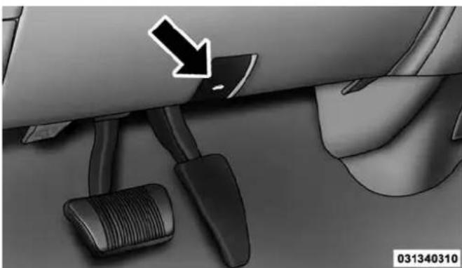
natural_image
Close-up of a car dashboard and steering wheel (no text or symbols visible)HoodRelease
- Reach into the opening beneath the center of the hood and push the safety latch lever to the left to release it, before raising the hood.
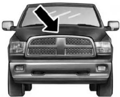
natural_image
Front view of a black-and-white image of a car with a downward arrow pointing to the grille (no text or symbols)031305529
SafetyLatchLocation(1500SeriesShown)
CAUTION!
Topreventpossibledamage, donotslamthehoodto closeit. Useafirmdownwardpushatthefrontcenter ofthehoodtoensurethatbothlatchesengage.
UNDERSTANDING THE FEATURES OF YOUR VEHICLE 149
WARNING!
Besurethehoodisfullylatchedbeforedrivingyour vehicle.Ifthehoodisnotfullylatched,itcouldopen whenthevehicleisinmotionandblockyourvision. Failuretofollowthiswarningcouldresultinserious injuryordeath.
LIGHTS
The headlight switch is located on the left side of the instrument panel, next to the steering wheel. The headlight switch controls the operation of the headlights, parking lights, instrument panel lights, cargo lights and fog lights (if equipped).
150 UNDERSTANDING THE FEATURES OF YOUR VEHICLE

natural_image
Interior view of a car dashboard and steering wheel (no visible text or symbols)HeadlightSwitchLocation
Your vehicle is equipped with plastic headlight and fog light (if equipped) lenses that are lighter and less susceptible to stone breakage than glass lights. Plastic is not as scratch resistant as glass and therefore different lens cleaning procedures must be followed.
To minimize the possibility of scratching the lenses and reducing light output, avoid wiping with a dry cloth. To remove road dirt, wash with a mild soap solution followed by rinsing.
NOTE: If your vehicle is equipped with illuminated approach lights under the outside mirrors they can be turned off through the instrument cluster or the Uconnect® radio. For further information refer to "EVIC" or "DID" and "Uconnect® Settings" in "Understanding Your Instrument Panel".
CAUTION!
Donotuseabrasivecleaningcomponents,solvents,steelwoolorotherabrasivematerialstocleanthe lenses.
Headlights

To turn on the headlights, rotate the headlight switch clockwise to the headlight position.
When the headlight switch is on, the parking lights, taillights, license plate light and instru-
ment panel lights are also turned on. To turn off the headlights, rotate the headlight switch back to the O (Off) position.
Automatic Headlights — If Equipped
This system automatically turns the headlights on or off according to ambient light levels. To turn the system on, rotate the headlight switch to the AUTO position.

031464204
AutomaticHeadlightPosition
When the system is on, the Headlight Delay feature is also on. This means the headlights will stay on for up to 90 seconds after you turn the ignition switch to the OFF position. To turn the automatic headlights off, turn the headlight switch out of the AUTO position.
152 UNDERSTANDING THE FEATURES OF YOUR VEHICLE
NOTE: The engine must be running before the headlights will turn on in the Automatic Mode.
Headlights On With Wipers (Available With Automatic Headlights Only)
When this feature is active, the headlights will turn on approximately 10 seconds after the wipers are turned on if the headlight switch is placed in the AUTO position. In addition, the headlights will turn off when the wipers are turned off, if they were turned on by this feature.
NOTE: If your vehicle is equipped with a touchscreen, this feature can be programmed through the Uconnect® system. Refer to "Uconnect® Settings" in "Understanding Your Instrument Panel" for further information.
If your vehicle is not equipped with a touchscreen, this feature can be programmed through the Electronic Vehicle Information Center (EVIC) or Driver Information Display (DID). Refer to "Electronic Vehicle Information Center (EVIC)" or "Driver Information Display (DID)" in "Understanding Your Instrument Panel" for further information.
Daytime Running Lights (DRL) — If Equipped
The headlights on your vehicle will illuminate when the engine is started and the transmission is in any gear except PARK. This provides a constant "Lights ON" condition until the ignition is turned OFF. The lights illuminate at less than 50% of normal intensity. If the parking brake is applied, the Daytime Running Lights (DRL) will turn OFF. Also, if a turn signal is activated, the DRL lamp on the same side of the vehicle may turn off for the duration of the turn signal activation. Once the turn signal is no longer active, the DRL lamp will illuminate.
Headlight Delay
To aid in your exit, your vehicle is equipped with a headlight delay that will leave the headlights on for approximately up to 90 seconds. This delay is initiated
when the ignition is turned OFF while the headlight switch is on, and then the headlight switch is cycled off. Headlight delay can be cancelled by either turning the headlight switch on then off, or by turning the ignition ON.
NOTE: If your vehicle is equipped with a touchscreen, this feature can be programmed through the Uconnect® system. Refer to "Uconnect® Settings" in "Understanding Your Instrument Panel" for further information.
If your vehicle is not equipped with a touchscreen, this feature can be programmed through the Electronic Vehicle Information Center (EVIC) or Driver Information Display (DID). Refer to “Electronic Vehicle Information Center (EVIC)” or “Driver Information Display (DID)” in “Understanding Your Instrument Panel” for further information.
UNDERSTANDING THE FEATURES OF YOUR VEHICLE 153
Automatic High Beam Headlamp Control — If Equipped
The Automatic High Beam Headlamp Control system provides increased forward lighting at night by automating high beam control through the use of a digital camera mounted on the inside rearview mirror. This camera detects vehicle specific light and automatically switches from high beams to low beams until the approaching vehicle is out of view.
NOTE:
- If your vehicle is equipped with a touchscreen the Automatic High Beam Headlamp Control can be turned on or off using the Uconnect® System. Refer to "Uconnect® Settings" in "Understanding Your Instrument Panel" for further information.
- If your vehicle is not equipped with a touchscreen the Automatic High Beam Headlamp Control can be
154 UNDERSTANDING THE FEATURES OF YOUR VEHICLE
turned on or off using the Electronic Vehicle Information Center (EVIC) or Driver Information Display (DID). Refer to "Electronic Vehicle Information Center (EVIC)" or "Driver Information Display (DID)" in "Understanding Your Instrument Panel" for further information.
- Broken, muddy, or obstructed headlights and taillights of vehicles in the field of view will cause headlights to remain on longer (closer to the vehicle). Also, dirt, film, and other obstructions on the windshield or camera lens will cause the system to function improperly.
- To opt out of the Advanced Auto High-Beam Sensitivity Control (default) and enter Reduced High-Beam Sensitivity Control (not recommended), toggle high-beam lever 6 full on/off cycles within 10 seconds of ignition ON. System will return to default setting upon ignition off.
If the windshield or Automatic High Beam Headlamp Control mirror is replaced, the mirror must be re-aimed to ensure proper performance. See your local authorized dealer.
ToActivate
- If your vehicle is equipped with a touchscreen, the Automatic High Beams are enabled through the Uconnect® system. Refer to "Uconnect® Settings" in "Understanding Your Instrument Panel" for further information.
If your vehicle is not equipped with a touchscreen, the Automatic High Beams are enabled through the Electronic Vehicle Information Center (EVIC) or Driver Information Display (DID). Refer to “Electronic Vehicle Information Center (EVIC)” or “Driver Information Display (DID)” in “Understanding Your Instrument Panel” for further information.
- Turn the headlight switch to the AUTO headlight position.
- Push the multifunction lever away from you (toward front of vehicle) to engage the high beam mode.
NOTE: This system will not activate until the vehicle is at or above 20 mph (32 km/h).
ToDeactivate
- Pull the multifunction lever toward you (or rearward in car) to manually deactivate the system (normal operation of low beams).
- Push back on the multifunction lever once again to reactivate the system.
UNDERSTANDING THE FEATURES OF YOUR VEHICLE 155
Parking Lights And Panel Lights
To turn on the parking lights and instrument panel lights, rotate the headlight switch clockwise. To turn off the parking lights, rotate the headlight switch back to the O (Off) position.
Fog Lights — If Equipped
The fog lights are turned on by rotating the headlight switch to the parking light or headlight position and pushing in the headlight rotary control.
156 UNDERSTANDING THE FEATURES OF YOUR VEHICLE
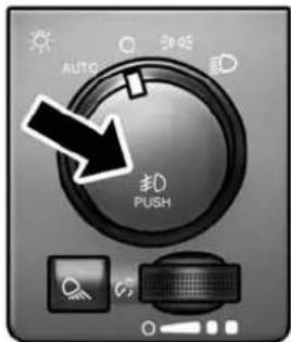
031464205
FogLightSwitch
The fog lights will operate only when the parking lights are on or when the vehicle headlights are on low beam. An indicator light located in the instrument cluster will illuminate when the fog lights are on. The fog lights will turn off when the switch is pushed a second time, when the headlight switch is rotated to the off position, or the high beam is selected.
Lights-On Reminder
If the headlights, parking lights, or cargo lights are left on after the ignition is turned OFF, a chime will sound when the driver's door is opened.
Battery Saver
To protect the life of your vehicle's battery, load shedding is provided for both the interior and exterior lights.
If the ignition is OFF and any door is left ajar for 10 minutes or the dimmer control is rotated all the way up to the dome ON position for 10 minutes, the interior lights will automatically turn off.
NOTE: Battery saver mode is cancelled if the ignition is ON.
If the headlights remain on while the ignition is cycled OFF, the exterior lights will automatically turn off after eight minutes. If the headlights are turned on and left on for eight minutes while the ignition is OFF, the exterior lights will automatically turn off.
Interior Lights
Courtesy and dome lights are turned on when the front doors are opened, when the dimmer control (rotating wheel on the bottom of the switch) is rotated to the far right detent position. If your vehicle is equipped with Remote Keyless Entry (RKE) and the UNLOCK button is pressed on the RKE transmitter the courtesy and dome lights will turn on. When a door is open and the interior lights are on, rotating the dimmer control all the way left, to the OFF detent, will cause all the interior lights to go out. This is also known as the "Party" mode because it allows the doors to stay open for extended periods of time without discharging the vehicle's battery.
UNDERSTANDING THE FEATURES OF YOUR VEHICLE 157
The brightness of the instrument panel as well as the ambient lighting can be regulated by rotating the dimmer control right (brighter) or left (dimmer). When the headlights are on you can supplement the brightness of the odometer, trip odometer, radio and overhead console by rotating the control to the right until you hear a click. This feature is termed the "Parade" mode and is useful when headlights are required during the day.
NOTE: If your vehicle is equipped with a touchscreen, the dimming of the touchscreen is programmable through the Uconnect® system. Refer to "Uconnect® Settings" in "Understanding Your Instrument Panel" for further details.
158 UNDERSTANDING THE FEATURES OF YOUR VEHICLE

DimmerControl
031464206
Courtesy/ReadingLights
Both lights in the overhead console and rear passenger compartment will illuminate as courtesy lights when a door is opened, when the dimmer control is rotated to the courtesy light position (full right position), or when the UNLOCK button is pressed on the Remote Keyless Entry
(RKE) transmitter, if equipped. These lights are also operated individually as reading lights by pressing on the corresponding lens.

natural_image
Interior view of a car dashboard with two directional control panels and a central touchscreen display (no text or symbols visible)FrontCourtesy/ReadingLights

natural_image
Microscopic view of a rod-shaped bacterial cell with a labeled arrow pointing to its interior (no text or symbols on the cell itself)RearPassengerCourtesy/ReadingLight
NOTE: The courtesy/reading lights will remain on until the switch is pressed a second time, so be sure they have been turned off before leaving the vehicle. If the interior lights are left on after the ignition is turned OFF, they will automatically turn off after 15 minutes.
UNDERSTANDING THE FEATURES OF YOUR VEHICLE 159
AmbientLight
The overhead console is equipped with an ambient light feature. This light casts illumination for improved visibility of the floor console area.

natural_image
Interior view of a car dashboard with control panel and directional arrow indicator (no text or symbols)AmbientLight
160 UNDERSTANDING THE FEATURES OF YOUR VEHICLE
Cargo Light
The cargo lights are turned on by pressing on the cargo button.

031464207
CargoLightSwitch
The cargo lights will also turn on for approximately 30 seconds when a RKE transmitter UNLOCK button is pressed, as part of the Illuminated Entry feature.
Multifunction Lever
The multifunction lever is located on the left side of the steering column.
Turn Signals
Move the multifunction lever up or down and the arrows on each side of the instrument cluster flash to show proper operation of the front and rear turn signal lights.

natural_image
Interior view of a car dashboard with steering wheel, speedometer, and control panel (no visible text or symbols)TurnSignalLever
NOTE: If either light remains on and does not flash, or there is a very fast flash rate, check for a defective outside light bulb. If an indicator fails to light when the lever is moved, it would suggest that the indicator bulb is defective.
UNDERSTANDING THE FEATURES OF YOUR VEHICLE 161
Lane Change Assist
Tap the lever up or down once, without moving beyond the detent, and the turn signal (right or left) will flash three times then automatically turn off.
Flash-To-Pass
You can signal another vehicle with your headlights by partially pulling the multifunction lever toward the steering wheel. This will cause the high beam headlights to turn on until the lever is released.
162 UNDERSTANDING THE FEATURES OF YOUR VEHICLE High/Low Beam Switch
Push the multifunction lever toward the instrument panel to switch the headlights to high beam. Pulling the multifunction lever back toward the steering wheel will turn the low beams back on, or shut the high beams off.
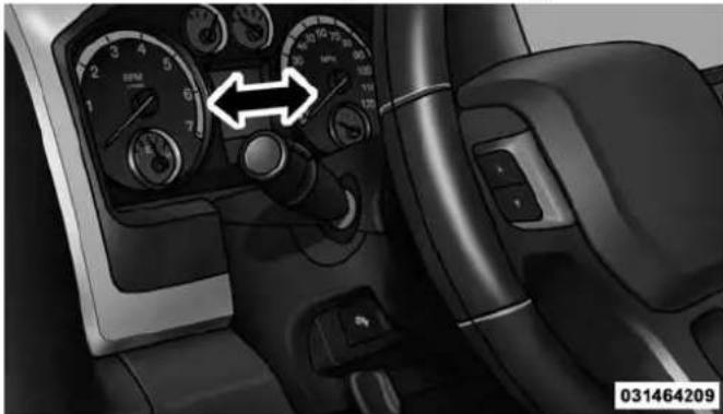
natural_image
Interior view of a car dashboard with steering wheel, speedometer, and control panel (no visible text or symbols)High/LowBeamSwitch
WINDSHIELD WIPERS AND WASHERS
Windshield Wipers
The wipers and washers are operated by a switch in the multifunction lever. Turn the end of the handle to select the desired wiper speed.
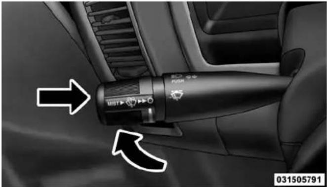
natural_image
Interior view of a car showing a black handheld device with directional arrows indicating left and right motion (no text or symbols on the device itself)WindshieldWiper/WasherSwitch
Windshield Wiper Operation
Rotate the end of the lever upward, to the first detent past the intermittent settings for low-speed wiper operation. Rotate the end of the lever upward to the second detent past the intermittent settings for high-speed wiper operation.
Intermittent Wiper System
The intermittent feature of this system was designed for use when weather conditions make a single wiping cycle, with a variable pause between cycles, desirable. For maximum delay between cycles, rotate the control knob into the upper end of the delay range.
The delay interval decreases as you rotate the knob until it enters the low continual speed position. The delay can be regulated from a maximum of about 18 seconds between cycles, to a cycle every one second. The delay intervals will double in duration when the vehicle speed is 10 mph (16 km/h) or less.
UNDERSTANDING THE FEATURES OF YOUR VEHICLE 163
Windshield Washers
To use the windshield washer, push the washer knob, located on the end of the multifunction lever, inward to the second detent. Washer fluid will be sprayed and the wiper will operate for two to three cycles after the washer knob is released from this position.
If the washer knob is depressed while in the delay range, the wiper will operate for several seconds after the washer knob is released. It will then resume the intermittent interval previously selected. If the washer knob is pushed while in the off position, the wiper will turn on and cycle approximately three times after the wash knob is released.
To prevent freeze-up of your windshield washer system in cold weather, select a solution or mixture that meets or exceeds the temperature range of your climate. This rating information can be found on most washer fluid containers.
164 UNDERSTANDING THE FEATURES OF YOUR VEHICLE
WARNING!
Suddenlossofvisibilitythroughthewindshield couldleadtoacollision.Youmightnotseeother vehiclesorotherobstacles.Toavoidsuddenicingof thewindshieldduringfreezingweather,warmthe windshieldwiththedefrosterbeforeandduring windshieldwasheruse.
Mist Feature
When a single wipe to clear off road mist or spray from a passing vehicle is needed, push the washer knob, located on the end of the multifunction lever, inward to the first detent and release. The wipers will cycle one time and automatically shut off.
NOTE: The mist feature does not activate the washer pump; therefore, no washer fluid will be sprayed on the windshield. The wash function must be used in order to spray the windshield with washer fluid.
Rain Sensing Wipers — If Equipped
This feature senses moisture on the windshield and automatically activates the wipers for the driver. The feature is especially useful for road splash or overspray from the windshield washers of the vehicle ahead. Rotate the end of the multifunction lever to one of five settings to activate this feature.
NOTE: If your vehicle is equipped with a touchscreen, this feature can be programmed through the Uconnect® system. Refer to "Uconnect® Settings" in "Understanding Your Instrument Panel" for further information.
If your vehicle is not equipped with a touchscreen, this feature can be programmed through the Electronic Vehicle Information Center (EVIC) or Driver Information Display (DID). Refer to "Electronic Vehicle Information Center (EVIC)" or "Driver Information Display (DID)" in "Understanding Your Instrument Panel" for further information.
The sensitivity of the system can be adjusted with the multifunction lever. Wiper delay position 1 is the least sensitive, and wiper delay position 5 is the most sensitive. Setting 3 should be used for normal rain conditions. Settings 1 and 2 can be used if the driver desires less wiper sensitivity. Setting 4 and 5 can be used if the driver desires more sensitivity. Place the wiper switch in the OFF position when not using the system.
NOTE:
- The Rain Sensing feature will not operate when the wiper switch is in the low or high-speed position.
- The Rain Sensing feature may not function properly when ice, or dried salt water is present on the windshield.
- Use of Rain-X® or products containing wax or silicone may reduce Rain Sensing performance.
UNDERSTANDING THE FEATURES OF YOUR VEHICLE 165
The Rain Sensing system has protection features for the wiper blades and arms, and will not operate under the following conditions:
- LowAmbientTemperature— When the ignition is first turned ON, the Rain Sensing system will not operate until the wiper switch is moved, vehicle speed is greater than 0 mph (0 km/h), or the outside temperature is greater than 32^ (0°C).
- TransmissionInNEUTRALPosition—When the ignition is ON, and the transmission is in the NEUTRAL position, the Rain Sensing system will not operate until the wiper switch is moved, vehicle speed is greater than 5 mph (8 km/h), or the shift lever is moved out of the NEUTRAL position.
166 UNDERSTANDING THE FEATURES OF YOUR VEHICLE
RemoteStartModeInhibit— On vehicles equipped with Remote Starting system, Rain Sensing wipers are not operational when the vehicle is in the remote start mode. Once the operator is in the vehicle and has placed the ignition switch in the RUN position, rain sensing wiper operation can resume, if it has been selected, and no other inhibit conditions (mentioned previously) exist.
TILT STEERING COLUMN
This feature allows you to tilt the steering column upward or downward. The tilt lever is located on the steering column, below the multifunction lever.
Pull the lever toward the steering wheel to unlock the steering column. With one hand firmly on the steering wheel, move the steering column up or down, as desired. Release the lever to lock the steering column firmly in place.

natural_image
Interior view of a car dashboard and steering wheel (no visible text or symbols)TiltSteeringLever
WARNING!
Donotadjustthesteeringcolumnwhiledriving. Adjustingthesteeringcolumnwhiledrivingordrivingwiththesteeringcolumnunlocked,couldcause
(Continued)
WARNING!(Continued)
thedrivertolosecontrolofthevehicle.Failureto followthiswarningmayresultinseriousinjuryor death.
DRIVER ADJUSTABLE PEDALS — IF EQUIPPED
The adjustable pedals system is designed to allow a greater range of driver comfort for steering wheel tilt and seat position. This feature allows the brake, accelerator, and clutch pedals (if equipped) to move toward or away from the driver to provide improved position with the steering wheel.
The adjustable pedal switch is located to the left side of the steering column.
UNDERSTANDING THE FEATURES OF YOUR VEHICLE 167

natural_image
Interior view of a car dashboard with steering wheel and dashboard controls (no visible text or symbols)AdjustablePedalsSwitch
• The pedals can be adjusted with the ignition OFF.
- The pedals cannot be adjusted when the vehicle is in REVERSE or when the Electronic Speed Control System is on. The following messages will be displayed on vehicles equipped with the Electronic Vehicle Information System (EVIC) or Driver Information Display (DID)
168 UNDERSTANDING THE FEATURES OF YOUR VEHICLE
if the pedals are attempted to be adjusted when the system is locked out ("Adjustable Pedal Disabled — Cruise Control Engaged" or "Adjustable Pedal Disabled — Vehicle In Reverse".
NOTE:
- Always adjust the pedals to a position that allows full pedal travel.
- Further small adjustments may be necessary to find the best possible seat/pedal position.
- For vehicles equipped with Driver Memory Seat, you can use your Remote Keyless Entry (RKE) transmitter or the memory switch on the driver's door trim panel to return the adjustable pedals to pre-programmed positions. Refer to "Driver Memory Seat" in "Understanding The Features Of Your Vehicle" for further information.
CAUTION!
Donotplaceanyarticleundertheadjustablepedals orimpedeitsabilitytomoveasitmaycausedamage tothepedalcontrols.Pedaltravelmaybecomelimitedifmovementisstoppedbyanobstructioninthe adjustablepedal'spath.
WARNING!
Donotadjustthepedalswhilethevehicleismoving. Youcouldlosecontrolandhaveanaccident.Always adjustthepedalswhilethevehicleisparked.
HEATED STEERING WHEEL — IF EQUIPPED
The steering wheel contains a heating element that helps warm your hands in cold weather. The heated steering wheel has only one temperature setting. Once the heated steering wheel has been turned on it will operate for up
to 80 minutes before automatically shutting off. The heated steering wheel can shut off early or may not turn on when the steering wheel is already warm.
The heated steering wheel control button is located within the Uconnect® system. You can gain access to the control button through the climate screen or the controls screen.
- Press the heated steering wheel button turn the heating element ON.
once to
- Press the heated steering wheel button time to turn the heating element OFF.
a second
NOTE: The engine must be running for the heated steering wheel to operate.
VehiclesEquippedWithRemoteStart
On models that are equipped with remote start, the heated steering wheel can be programmed to come on
UNDERSTANDING THE FEATURES OF YOUR VEHICLE 169
during a remote start through the Uconnect® system. Refer to "Uconnect® Settings" in "Understanding Your Instrument Panel" for further information.
WARNING!
- Personswhoareunabletofeelpaintotheskin becauseofadvancedage,chronicillness,diabetes, spinalcordinjury,medication,alcoholuse,exhaustion,orotherphysicalconditionsmustexercise carewhenusingthesteeringwheelheater.Itmay causeburnsevenatlowtemperatures,especiallyif usedforlongperiods.
- Donotplaceanythingonthesteeringwheelthat insulatesagainstheat,suchasablanketorsteering wheelcoversofanytypeandmaterial.Thismay causethesteeringwheelheatertooverheat.
170 UNDERSTANDING THE FEATURES OF YOUR VEHICLE ELECTRONIC SPEED CONTROL
When engaged, the Electronic Speed Control takes over accelerator operations at speeds greater than 25 mph (40 km/h).
The Electronic Speed Control buttons are located on the right side of the steering wheel.

ElectronicSpeedControlSwitches
1—ON/OFF 3—SET-
2 — RES + 4 — CANCEL
UNDERSTANDING THE FEATURES OF YOUR VEHICLE 171
NOTE: In order to ensure proper operation, the Electronic Speed Control System has been designed to shut down if multiple Speed Control functions are operated at the same time. If this occurs, the Electronic Speed Control System can be reactivated by pushing the Electronic Speed Control ON/OFF button and resetting the desired vehicle set speed.
To Activate
Push the ON/OFF button. The Cruise Indicator Light in the instrument cluster will illuminate. To turn the system off, push the ON/OFF button a second time. The Cruise Indicator Light will turn off. The system should be turned off when not in use.
WARNING!
LeavingtheElectronicSpeedControlsystemon whennotinuseisdangerous.Youcouldaccidentally setthesystemorcauseittogofasterthanyouwant. Youcouldlosecontrolandhaveanaccident.Always leavethesystemOFFwhenyouarenotusingit.
To Set A Desired Speed
Turn the Electronic Speed Control ON. When the vehicle has reached the desired speed, press the SET (-) button and release. Release the accelerator and the vehicle will operate at the selected speed.
NOTE: The vehicle should be traveling at a steady speed and on level ground before pressing the SET (-) button.
172 UNDERSTANDING THE FEATURES OF YOUR VEHICLE
To Deactivate
A soft tap on the brake pedal, pushing the CANCEL button, or normal brake pressure while slowing the vehicle will deactivate the Electronic Speed Control without erasing the set speed from memory.
Pressing the ON/OFF button or turning the ignition switch OFF erases the set speed from memory.
To Resume Speed
To resume a previously set speed, push the RES (+) button and release. Resume can be used at any speed above 20 mph (32 km/h).
To Vary The Speed Setting
ToIncreaseSpeed
When the Electronic Speed Control is set, you can increase speed by pushing the RES (+) button.
The drivers preferred units can be selected through the instrument panel settings if equipped. Refer to “Understanding Your Instrument Panel” for more information. The speed increment shown is dependant on the chosen speed unit of U.S. (mph) or Metric (km/h):
U.S.Speed(mph)
- Pressing the RES (+) button once will result in a 1 mph increase in set speed. Each subsequent tap of the button results in an increase of 1 mph.
- If the button is continually pressed, the set speed will continue to increase until the button is released, then the new set speed will be established.
MetricSpeed(km/h)
- Pressing the RES (+) button once will result in a 1 km/h increase in set speed. Each subsequent tap of the button results in an increase of 1 km/h.
- If the button is continually pressed, the set speed will continue to increase until the button is released, then the new set speed will be established.
ToDecreaseSpeed
When the Electronic Speed Control is set, you can decrease speed by pushing the SET (-) button.
The drivers preferred units can be selected through the instrument panel settings if equipped. Refer to “Understanding Your Instrument Panel” for more information. The speed decrement shown is dependant on the chosen speed unit of U.S. (mph) or Metric (km/h):
U.S.Speed(mph)
- Pressing the SET (-) button once will result in a 1 mph decrease in set speed. Each subsequent tap of the button results in a decrease of 1 mph.
UNDERSTANDING THE FEATURES OF YOUR VEHICLE 173
- If the button is continually pressed, the set speed will continue to decrease until the button is released, then the new set speed will be established.
MetricSpeed(km/h)
- Pressing the SET (-) button once will result in a 1 km/h decrease in set speed. Each subsequent tap of the button results in a decrease of 1 km/h.
- If the button is continually pressed, the set speed will continue to decrease until the button is released, then the new set speed will be established.
To Accelerate For Passing
Press the accelerator as you would normally. When the pedal is released, the vehicle will return to the set speed.
UsingElectronicSpeedControlOnHills
The transmission may downshift on hills to maintain the vehicle set speed.
174 UNDERSTANDING THE FEATURES OF YOUR VEHICLE
NOTE: The Electronic Speed Control system maintains speed up and down hills. A slight speed change on moderate hills is normal.
On steep hills, a greater speed loss or gain may occur so it may be preferable to drive without Electronic Speed Control.
WARNING!
ElectronicSpeedControlcanbedangerouswherethe systemcannotmaintainaconstantspeed.Yourvehiclecouldgotoofastfortheconditions,andyou couldlosecontrolandhaveanaccident.Donotuse ElectronicSpeedControlinheavytrafficoronroads thatarewinding,icy,snow-coveredorslippery.
OVERHEAD CONSOLE — IF EQUIPPED
The overhead console is located on the headliner above the rearview mirror. The overhead console contains the following features:
•Courtesy/Reading Lights
- Power Sliding Rear Window Switch — If Equipped

natural_image
Interior view of a car air conditioner unit with control panel and directional arrow (no text or symbols)OverheadConsole
Courtesy/Reading Lights
Both lights in the overhead console and rear passenger compartment will illuminate as courtesy lights when a door is opened, when the dimmer control is rotated to the courtesy light position (full right position), or when the UNLOCK button is pressed on the Remote Keyless Entry
UNDERSTANDING THE FEATURES OF YOUR VEHICLE 175
(RKE) transmitter, if equipped. These lights are also operated individually as reading lights by pressing on the corresponding lens.

natural_image
Interior view of a car dashboard with two directional control panels and a central touchscreen display (no text or symbols visible)FrontCourtesy/ReadingLights
176 UNDERSTANDING THE FEATURES OF YOUR VEHICLE

natural_image
Microscopic view of a rod-shaped biological structure with a circular end, marked by an arrow pointing to a specific region (no text or symbols present)RearPassengerCourtesy/ReadingLight
NOTE: The courtesy/reading lights will remain on until the switch is pressed a second time, so be sure they have been turned off before leaving the vehicle. If the interior lights are left on after the ignition is turned OFF, they will automatically turn off after 15 minutes.
ELECTRICAL POWER OUTLETS
The auxiliary 12 Volt (13 Amp) power outlets can provide power for in-cab accessories designed for use with the standard "cigar lighter" plug. The 12 Volt power outlets have a cap attached to the outlet indicating "12V DC," together with either a key symbol or a battery symbol.
A key symbol indicates that the key must be in the ON/RUN or ACC positions for the outlet to provide power. The battery symbol indicates that the outlet is connected to the battery, and can provide power at all times.
NOTE: To ensure proper operation, a MOPAR® knob and element must be used.
The auxiliary power outlets can be found in the following locations:
CAUTION!
- Donotexceedthemaximumpowerof160Watts(13 Amps)at12Volts.Ifthe160Watts(13Amps)power ratingisexceeded,thefuseprotectingthesystem willneedtobereplaced.
- Poweroutletsaredesignedforaccessoryplugs only.Donotinsertanyotherobjectinthepower outletsasthiswilldamagetheoutletandblowthe fuse.Improperuseofthepoweroutletcancause damagenotcoveredbyyourNewVehicleLimited Warranty.
UNDERSTANDING THE FEATURES OF YOUR VEHICLE 177
- Lower left and lower right of the center stack when equipped with a bench seat.

PowerOutlets—CenterStack
1 — Power Outlet
2 — USB Port (Charge Only)
178 UNDERSTANDING THE FEATURES OF YOUR VEHICLE
• Center console when equipped with bucket seats.
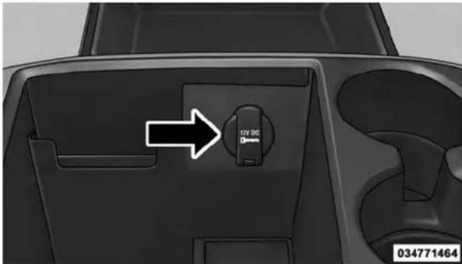
PowerOutlet—CenterConsole
- Inside the upper lid of the center storage compartment — if equipped.

PowerOutlet—UpperLid
- Rear of the center console storage compartment — Quad Cab® or Crew Cab.

natural_image
Interior view of a vehicle air conditioner unit with control panel and directional arrow (no text or symbols)PowerOutlet—RearCenterConsole
UNDERSTANDING THE FEATURES OF YOUR VEHICLE 179

PowerOutlet—RearCenterConsoleFuse
180 UNDERSTANDING THE FEATURES OF YOUR VEHICLE
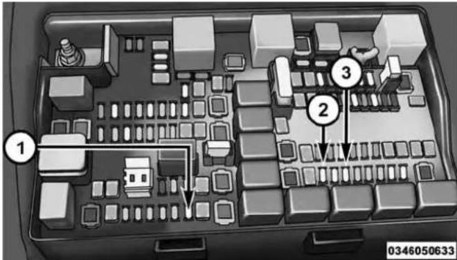
PowerOutletFuseLocations
1 — F104 Fuse 20 A Yellow Power Outlet Console Bin
2 — F90-F91 Fuse 20 A Yellow Power Outlet Rear Center Console
3 — F93 Fuse 20 A Yellow Cigar Lighter Instrument Panel
The key symbol indicates that this outlet can supply power when the key is in the ON/RUN or ACC positions.
All accessories connected to the outlet(s) should be removed or turned off when the vehicle is not in use to protect the battery against discharge.
WARNING!
Toavoidseriousinjuryordeath:
- Onlydevicesdesignedforuseinthistypeofoutlet shouldbeinsertedintoany12Voltoutlet.
- Donottouchwithwethands.
- Closethelidwhennotinuseandwhiledrivingthe vehicle.
- If this outletismishandled, it may cause an electric shock and failure.
CAUTION!
- Manyaccessories that can be plugged in draw power from the vehicle's battery, even when not in use (i.e., cellular phones, etc.). Eventually, if plugged in longenough, the vehicle's battery will discharges sufficiently to degrade battery life and/or prevent the engine from starting.
- Accessories that draw higher power (i.e., coolers, vacuum cleaners, lights, etc.), will discharge the battery even more quickly. Only us these intermittently and with greater caution.
- Aftertheuseofhighpowerdrawaccessories,or longperiodsofthevehiclenotbeingstarted(with accessoriesstillpluggedin),thevehiclemustbe drivenasufficientlengthoftimetoallowthe generatortorechargethevehicle'sbattery.
AUXILIARY SWITCHES — IF EQUIPPED
There can be up to five auxiliary switches located in the lower switch bank of the instrument panel which can be used to power various electronic devices and PTO (Power Take Off) – If Equipped. Connections to the switches are found under the hood in the connectors attached to the auxiliary Power Distribution Center.
You have the ability to configure the functionality of the auxiliary switches via the Electronic Vehicle Information Center (EVIC) or Driver Information Display (DID). All switches can now be configured for ignition or battery power, saving or not saving state across a key cycle, and momentary or latching switch operation.
For further information on using the auxiliary switches, please refer to the Ram Body Builders Guide by accessing www.rambodybuilder.com and choosing the appropriate links.
182 UNDERSTANDING THE FEATURES OF YOUR VEHICLE CIGAR LIGHTER AND ASH RECEIVER — IF EQUIPPED
A removable ash receiver and cigar lighter are available. For vehicles with a bench seat the cupholder tray can be used to hold the ash receiver.

CigarLighterandAshReceiver(BenchSeat)
1 — Cigar Lighter
2 — Ash Receiver
For vehicles equipped with a floor console, the cupholders may be used.
UNDERSTANDING THE FEATURES OF YOUR VEHICLE 183
POWER INVERTER — IF EQUIPPED
A 115 Volt (150 Watts Maximum) outlet is located on the center stack of the instrument panel, to the right of the radio. This outlet can power cellular phones, electronics and other low power devices requiring power up to 150 Watts. Certain high-end video games, such as PlayStation3 and XBox360 will exceed this power limit, as will most power tools.
The power inverter is designed with built-in overload protection. If the power rating of 150 Watts is exceeded, the power inverter will automatically shut down. Once the electrical device has been removed from the outlet the inverter should automatically reset.
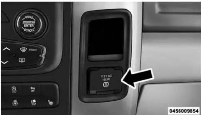
PowerInverterOutlet
To turn on the power outlet, simply plug in the device. The outlet automatically turns off when the device is unplugged.
NOTE: Due to built-in overload protection, the power inverter will shut down if the power rating is exceeded.
184 UNDERSTANDING THE FEATURES OF YOUR VEHICLE
WARNING!
Toavoidseriousinjuryordeath:
- Donotinsertanyobjectsintothereceptacles.
• Donottouchwithwethands.
• Closethelidwhennotinuse. - If this outletismishandled, it may cause an electric shock and failure.
CUPHOLDERS
Front Seat Cupholders (40–20–40 Seats)
The cupholders are located on the backside of the center portion of the front seat (20). Fold down the center section of the front seat to gain access to the cupholders.
Front Instrument Panel Cupholders — Floor Storage Bin
For vehicles equipped with bucket seats two cupholders are located in the floor storage bin.

natural_image
Interior view of a car dashboard with two compartments and a handle, showing no text or symbols.FrontCupholdersForBucketSeats
Rear Cupholders — If Equipped
Some vehicles are equipped with rear cupholders located in the center armrest.

natural_image
Interior view of a car showing rear seats and seatbelt, with a black arrow pointing to the seat (no text or symbols on the main subject)RearArmrestCupholder
UNDERSTANDING THE FEATURES OF YOUR VEHICLE 185
Some vehicles may be equipped with a rear cupholder that consists of two cup wells for rear passenger convenience.
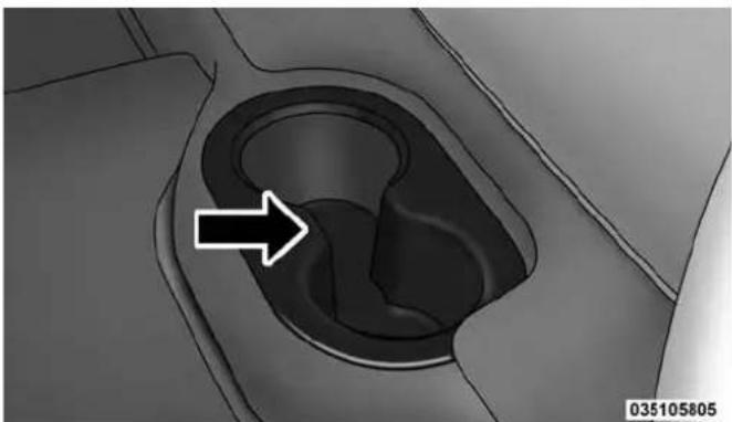
natural_image
Close-up of a car intake canal with an arrow pointing to the opening area (no text or symbols)RearCupWells
186 UNDERSTANDING THE FEATURES OF YOUR VEHICLE
STORAGE
Glove Compartment
The glove compartment is located on the passenger side of the instrument panel and features both an upper and lower storage area.

GloveCompartment
1 — Upper Glove Compartment
2 — Lower Glove Compartment
To open the upper glove compartment push upward on the handle release. The glove compartment door will automatically open.

natural_image
Interior view of a car dashboard and air vent system (no visible text or symbols)UpperGloveCompartment
UNDERSTANDING THE FEATURES OF YOUR VEHICLE 187
To open the lower glove compartment, pull on the handle to release the latch and lower the glove compartment door.

natural_image
Interior view of a car showing the hood, front panel, and side-mounted air conditioner unit (no visible text or symbols)LowerGloveCompartment
188 UNDERSTANDING THE FEATURES OF YOUR VEHICLE
Door Storage
FrontDoorStorage—IfEquipped
Storage areas and bottle holders (drivers side only) are located in the door trim panels.
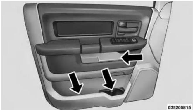
natural_image
Interior view of a car dashboard with directional arrows indicating movement or flow (no text or symbols)FrontDoorStorage
RearDoorStorage—IfEquipped
Storage compartments are located in both the driver and passenger rear door trim panels.

natural_image
Interior view of a car showing the backrest door and side panel with two arrows indicating direction (no text or symbols)RearDoorStorage
Center Storage Compartment — If Equipped
The center storage compartment is located between the driver and passenger seats. The storage compartment provides an armrest and contains both and upper and lower storage area.
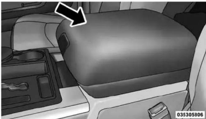
natural_image
Interior view of a car showing the rear seat and dashboard with a white arrow pointing to the side (no text or symbols on the main subject)CenterStorageCompartment
UNDERSTANDING THE FEATURES OF YOUR VEHICLE 189
WARNING!
- Thisarmrestisnotaseat.Anyoneseatedonthe armrestcouldbeseriouslyinjuredduringvehicle operation,oracollision.Onlyusethecenterseatingpositionwhenthearmrestisfullyupright.
- Inacollision, the latch may open if the total weight of the items stored exceeds about 10 lbs (4.5 kg). These items could be thrown about endangering occupants of the vehicle. Items stored should not exceed at total of 10 lbs (4.5 kg).
Pull on the upper handle on the front of the armrest to raise the cover. The upper storage area contains a 12 Volt power outlet that can be used to power small electrical devices, refer to "Electrical Power Outlets" for further information.
190 UNDERSTANDING THE FEATURES OF YOUR VEHICLE

natural_image
Interior view of a car dashboard with seats and a backseat, featuring a white arrow pointing to the seat area (no text or symbols on the main objects)UpperStorageCompartmentLowerStorageBin
With the upper lid closed, pull on the lower handle to open the lower storage bin.
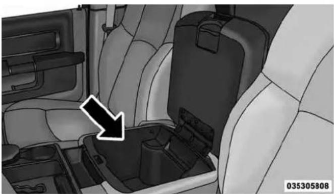
natural_image
Interior view of a car showing the rear seats and seat compartments with a black arrow pointing to one seat (no text or symbols on the main objects)WARNING!
Donotoperatethisvehiclewithaconsolecompartmentlidintheopenposition.Drivingwiththeconsolecompartmentlidopenmayresultininjuryinacollision.
Seatback Storage
Located in the back of both the driver and passenger front seats are pockets that can be used for storage.

natural_image
Interior view of a car showing the rear seat, dashboard, and air vent (no text or symbols visible)DriversSideSeatbackStorageStorageBin
UNDERSTANDING THE FEATURES OF YOUR VEHICLE 191
Storage (Regular Cab)
The storage bin is located behind the front seats and runs the length of the cab.
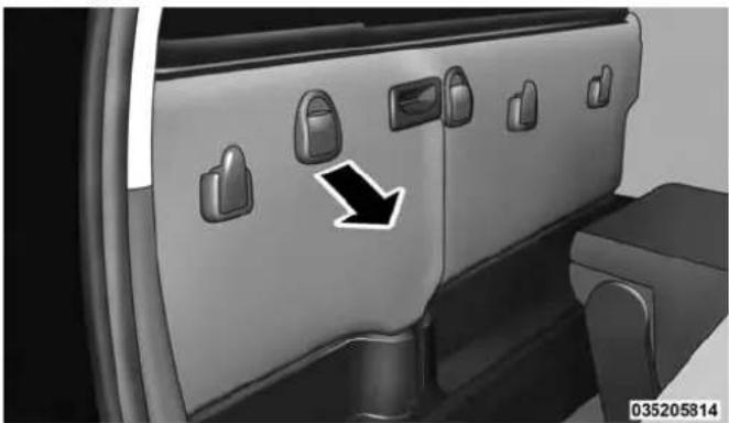
natural_image
Interior view of a car showing the door panel with lock icons and a black arrow pointing to a specific area (no text or symbols present)192 UNDERSTANDING THE FEATURES OF YOUR VEHICLE
Storage and Seats (Crew Cab)
The Crew Cab models provide additional storage under the rear seats. Lift the seats to access the storage compartment.
To open the storage compartments, lift upward on the handle of the latch and open the lid.

natural_image
Interior view of a vehicle showing a seatbelt mechanism with two arrows pointing to the side (no text or symbols present)CrewCabStorage
CAUTION!
Alwaysliftthestoragecompartmentlidsbyusing thehandle.Failureretoliftthelidsbyusingthehandle canresultindamagetothelids.
Plastic Grocery Bag Retainers (Regular Cab Models)
Retainer hooks which will hold plastic grocery bag handles are built into the back panel of the cab, behind the rear seat.

natural_image
Interior view of a car showing three directional arrows pointing to the door panel (no text or symbols present)GroceryBagHooks
UNDERSTANDING THE FEATURES OF YOUR VEHICLE 193
REAR WINDOW FEATURES
Rear Window Defroster

The rear window defroster button is located on the climate control panel. Press this button to turn on the rear window defroster and the heated outside mirrors (if equipped). An indicator in the button will illuminate when the rear window defroster is on. The rear window defroster automatically turns off after approximately 10 minutes. For an additional five minutes of operation, press the button a second time.
NOTE: To prevent excessive battery drain, use the rear window defroster only when the engine is operating.
194 UNDERSTANDING THE FEATURES OF YOUR VEHICLE
CAUTION!
Failure to follow these cautions can cause damage to the heating elements:
- Usecarewhenwashingtheinsideoftherear window.Donotuseabrasivewindowcleanerson theinteriorsurfaceofthewindow.Useasoftcloth andamildwashingsolution,wipingparallelttothe heatingelements.Labelscanbepeeledoffafter soakingwithwarmwater.
- Donotusescrapers, sharpinstruments, or abrasive windowcleanersontheinteriorsurfaceofthe window.
- Keepallobjectsasafedistancefromthewindow.
Power Sliding Rear Window — If Equipped
The switch for the power sliding rear window is located on the overhead console.
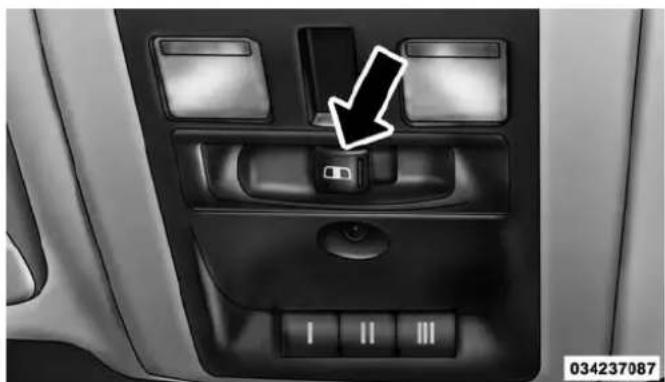
natural_image
Interior view of a car dashboard with control panel and directional arrow (no text or symbols)RearWindowSwitch
Push the switch to the right to open the glass. Pull the switch to the left to close the glass.
Manual Sliding Rear Window — If Equipped
A locking device in the center of the window helps to prevent entry from the rear of the vehicle. Squeeze the lock to release the window.
UNDERSTANDING YOUR INSTRUMENT PANEL
CONTENTS
■INSTRUMENT PANEL FEATURES....198
■INSTRUMENT CLUSTER — BASE. . . . . . . . . . . .199
■Uconnect® SETTINGS....259
□Buttons On The Faceplate. . . . . . . . . . . . . . . . . . . . . . . . . . . . . . . . . . . . . . . . . . . . . . . 261
□Buttons On The Touchscreen. . . . . . . . . . . . . . . . . . . . . . . . . . . . . . . . . . . . . . . . . . . . . . . . . . . 261
■Uconnect® RADIOS — IF EQUIPPED .....278
■iPod®/USB/MP3 CONTROL — IF EQUIPPED . .278
■STEERING WHEEL AUDIO CONTROLS — IF EQUIPPED....279
□Radio Operation....280
□CD Player — If Equipped. . . . . . . . . . . . . . . . . . . . . . . . . . . . . . . . . . . . . . . . . . . . . . 280
■CD/DVD DISC MAINTENANCE....280
□ Regulatory And Safety Information .....281
■CLIMATE CONTROLS....283
□Manual Climate Controls Without Touchscreen — If Equipped . . . . . . . . . . . . . . . . . . . . . . . . . . . . . . . . . . . . . . . . . . . . . . . . . . . . . . . . . 283
□Manual Climate Controls With Touchscreen — If Equipped....288
□Automatic Climate Controls With Touchscreen — If Equipped . . . . . . . . . . . . . . . . . . . . . . . . . . . . . . . . . . . . . . . . . . . . . . . . . . . . . . . . . . . . . . . . 293
□Climate Control Functions .....299
□Automatic Temperature Control (ATC) . . . . . .301
□Operating Tips....303
■Uconnect® VOICE RECOGNITION .....306
□Introducing Uconnect®. . . . . . . . . . . . . . . . . . . . . . . . . . . . . . . . . . . . . . . . . . . . 306
□Get Started....307
UNDERSTANDING YOUR INSTRUMENT PANEL 197
□Basic Voice Commands. . . . . . . . . . . . . . . . . . . . . . . . . . . . . . . 308
□Radio....310
□Media. 311
□Climate (8.4A/8.4AN)....313
□Navigation (8.4A/8.4AN)....314
□Phone....315
□Voice Text Reply....316
□Uconnect® Access* (8.4A/8.4AN)....317
□Register (8.4A/8.4AN)....318
□Mobile App (8.4A/8.4AN) . . . . . . . . . . . . . . . . . . . . . . . 319
□Voice Texting (8.4A/8.4AN)....320
□Yelp® (8.4A/8.4AN). .320
□SiriusXM Travel Link™ (8.4A/8.4AN) .....322
□Additional Information....323
198 UNDERSTANDING YOUR INSTRUMENT PANEL
INSTRUMENT PANEL FEATURES
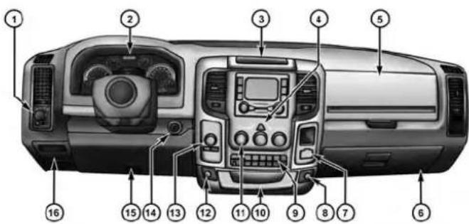
040170075
1 — Headlight Switch 7 — 115v Power Inverter Outlet 13 — Gear Selector/Transfer Case
2 — Instrument Cluster 8 — Power Outlet — If Equipped 14 — Ignition Switch
3 — Radio 9 — Lower Switch Bank 15 — Hood Release
4 — Hazard Switch 10 — Instrument Panel Drawer 16 — Parking Brake Release
5 — Upper Glove Compartment 11 — Climate Controls
6 — Lower Glove Compartment 12 — Power Outlet/Cigar Lighter — If Equipped
Position Switch — If Equipped
INSTRUMENT CLUSTER — BASE

0403017342
200 UNDERSTANDING YOUR INSTRUMENT PANEL
The tachometer indicates engine speed in Revolutions Per Minute (RPM x 1000).
CAUTION!
Donotoperatetheenginewiththetachometer pointerathighRPMforextendedperiods.Engine operationover3200RPMcanresultinsignificant damagethatwillnotbecoveredundertheNew VehicleLimitedWarranty.
2. Anti-Lock Brake (ABS) Light

This light monitors the Anti-lock Brake System (ABS). The light will turn on when the ignition switch is turned to the ON/RUN position and may stay on for as long as four seconds.
UNDERSTANDING YOUR INSTRUMENT PANEL
201
If the ABS light remains on or turns on while driving, it indicates that the anti-lock portion of the brake system is not functioning and that service is required. However, the conventional brake system will continue to operate normally if the BRAKE warning light is not on.
If the ABS light is on, the brake system should be serviced as soon as possible to restore the benefits of anti-lock brakes. If the ABS light does not turn on when the ignition switch is turned to the ON/RUN position, have the light inspected by an authorized dealer.
3. MalfunctionIndicatorLight(MIL)
The Malfunction Indicator Light (MIL) is part of an onboard diagnostic (OBDII) system which monitors the emissions and engine control system. If the vehicle is ready for emissions testing, the light will come on when the ignition is first turned on and remain on, as a bulb check, until the engine is started. If the vehicle is not ready for emissions
202 UNDERSTANDING YOUR INSTRUMENT PANEL
testing the light will come on when the ignition is first turned on and remain on for 15 seconds, then blink for 5 seconds, and remain on until the vehicle is started. If the bulb does not come on during starting, have the condition investigated promptly.
If this light comes on and remains on while driving, it suggests a potential engine control problem and the need for system service.
Although your vehicle will usually be drivable and not need towing, see your authorized dealer for service as soon as possible.
CAUTION!
ProlongeddrivingwiththeMalfunctionIndicator Light(MIL)oncouldcausedamagetotheengine controlsystem.Italsocouldaffectfueleconomyand driveability.IftheMILisflashing,severecatalytic
(Continued)
CAUTION!(Continued)
converterdamageandpowerlosswillsoonoccur. Immediateserviceisrequired.
WARNING!
Amalfunctioningcatalyticconverter, as referenced above, can reach high temperature than innormal operating conditions. This can cause a fire if you drive slowly or park over flammable substances such as dry plants, wood, cardboard, etc. This could result in deathor serious injury to the driver, occupants or others.
4. TurnSignalIndicators

The arrow will flash with the exterior turn signal when the turn signal lever is operated.
UNDERSTANDING YOUR INSTRUMENT PANEL 203
NOTE:
- A continuous chime will sound if the vehicle is driven more than 1 mile (1.6 km) with either turn signal on.
- Check for an inoperative outside light bulb if either indicator remains on and does not flash, or flashes at a rapid rate.
5.Voltmeter

When the engine is running, the gauge indicates the electrical system voltage. The pointer should within the normal range if the battery is charged. If inter moves to either extreme left or right and as there during normal driving, the electrical sys-ould be serviced.
NOTE: The voltmeter may show a gauge fluctuation at various engine temperatures. This cycling operation is caused by the post-heat cycle of the intake manifold heater system. The number of cycles and the length of the cycling operation is controlled by the engine control module. Post-heat operation can run for several minutes, and then the electrical system and voltmeter needle will stabilize.
6.BrakeWarningLight
BRAKE This light monitors various brake functions, including brake fluid level and parking brake application. If the brake light turns on it may indicate that the parking brake is applied, that the brake fluid level is low, or that there is a problem with the Anti-lock Brake System reservoir.
If the light remains on when the parking brake has been disengaged, and the fluid level is at the full mark on the master cylinder reservoir, it indicates a possible brake
204 UNDERSTANDING YOUR INSTRUMENT PANEL
hydraulic system malfunction or that a problem with the Brake Booster has been detected by the Anti-Lock Brake System (ABS) / Electronic Stability Control (ESC) system. In this case, the light will remain on until the condition has been corrected. If the problem is related to the brake booster, the ABS pump will run when applying the brake and a brake pedal pulsation may be felt during each stop.
The dual brake system provides a reserve braking capacity in the event of a failure to a portion of the hydraulic system. A leak in either half of the dual brake system is indicated by the Brake Warning Light, which will turn on when the brake fluid level in the master cylinder has dropped below a specified level.
The light will remain on until the cause is corrected.
NOTE: The light may flash momentarily during sharp cornering maneuvers, which change fluid level conditions. The vehicle should have service performed, and the brake fluid level checked.
If brake failure is indicated, immediate repair is necessary.
WARNING!
Drivingvehiclewiththeredbrakelightonis dangerous.Partofthebrakesystemmayhavefailed. Itwilltakelongertostopthevehicle.Youcouldhave acollision.Havethevehiclecheckedimmediately.
Vehicles equipped with the ABS, are also equipped with Electronic Brake Force Distribution (EBD). In the event of an EBD failure, the Brake Warning Light will turn on along with the ABS Light. Immediate repair to the ABS system is required.
Operation of the Brake Warning Light can be checked by turning the ignition switch from the OFF position to the ON/RUN position. The light should illuminate for approximately two seconds. The light should then turn off
unless the parking brake is applied or a brake fault is detected. If the light does not illuminate, have the light inspected by an authorized dealer.
The light also will turn on when the parking brake is applied with the ignition switch in the ON/RUN position.
NOTE: This light shows only that the parking brake is applied. It does not show the degree of brake application.
7. HighBeamIndicator

This light shows that the high beam headlights are on. Push the multifunction control lever away from you to switch the headlights to high beam. Pull the lever toward you to switch the headlights back to low beam. If the driver's door is open, and the headlights or park lights are left on, the high beam indicator light will remain illuminated and a chime will sound.
8.SeatBeltReminderLight

When the ignition switch is first turned to ON/RUN, this light will turn on for four to eight seconds as a bulb check. During the bulb check, if the driver's seat belt is unbuckled, a chime will sound. After the bulb check or when driving, if the driver's seat belt remains unbuckled, the seat belt reminder light will flash or remain on continuously. Refer to "Occupant Restraints" in "Things To Know Before Starting Your Vehicle" for further information.
9.AirBagWarningLight

This light will turn on for four to eight seconds as a bulb check when the ignition switch is first turned to ON/RUN. If the light is either not on during starting, stays on, or turns on while
driving, have the system inspected at an authorized dealer as soon as possible. Refer to “Occupant Restraints” in “Things To Know Before Starting Your Vehicle” for further information.
206 UNDERSTANDING YOUR INSTRUMENT PANEL
10.OilPressureGauge—IfEquipped
The pointer should always indicate some oil pressure when the engine is running. A continuous high or low reading under normal driving conditions may indicate a lubrication system malfunction. Immediate service should be obtained from an authorized dealer.
11.Speedometer
The speedometer shows the vehicle speed in miles per hour and/or kilometers per hour (mph/km/h).
12. Park/HeadlightONIndicator—IfEquipped

This indicator will illuminate when the park lights or headlights are turned on.
13.CargoLight—IfEquipped

The cargo light will illuminate when the cargo light is activated by pressing the cargo light button on the headlight switch.
14.FuelGauge
Shows level of fuel in tank when ignition switch is in the ON/RUN position.
15. VehicleSecurityLight—IfEquipped

This light will flash at a fast rate for approximately 15 seconds, when the vehicle security alarm is arming, and then will flash slowly until the vehicle is disarmed.
16. TirePressureMonitoringTelltaleLight—IfEquipped

Each tire, including the spare (if provided), should be checked monthly when cold and inflated to the inflation pressure recommended by the vehicle manufacturer on the vehicle placard or tire inflation pressure label. (If your vehicle has tires of a different size than the size indicated on the vehicle placard or tire inflation pressure label, you should determine the proper tire inflation pressure for those tires.)
As an added safety feature, your vehicle has been equipped with a Tire Pressure Monitoring System (TPMS) that illuminates a low tire pressure telltale when one or more of your tires is significantly under-inflated. Accordingly, when the low tire pressure telltale illuminates, you should stop and check your tires as soon as possible, and inflate them to the proper pressure. Driving on a significantly under-inflated tire causes the tire to
UNDERSTANDING YOUR INSTRUMENT PANEL 207
overheat and can lead to tire failure. Under-inflation also reduces fuel efficiency and tire tread life, and may affect the vehicle's handling and stopping ability.
Please note that the TPMS is not a substitute for proper tire maintenance, and it is the driver's responsibility to maintain correct tire pressure, even if under-inflation has not reached the level to trigger illumination of the TPMS low tire pressure telltale.
Your vehicle has also been equipped with a TPMS malfunction indicator to indicate when the system is not operating properly. The TPMS malfunction indicator is combined with the low tire pressure telltale. When the system detects a malfunction, the telltale will flash for approximately one minute and then remain continuously illuminated. This sequence will continue upon subsequent vehicle start-ups as long as the malfunction exists. When the malfunction indicator is illuminated, the system may not be able to detect or signal low tire pressure as intended. TPMS malfunctions may occur for a variety
208 UNDERSTANDING YOUR INSTRUMENT PANEL
of reasons, including the installation of replacement or alternate tires or wheels on the vehicle that prevent the TPMS from functioning properly. Always check the TPMS malfunction telltale after replacing one or more tires or wheels on your vehicle, to ensure that the replacement or alternate tires and wheels allow the TPMS to continue to function properly.
CAUTION!
TheTPMShasbeenoptimizedfortheoriginal equipmenttiresandwheels.TPMSpressuresand warninghavebeenestablishedforthetiresize equippedonyourvehicle.Undesirablesystemoperationorsensordamagemayresultwhenusingreplacementequipmentthatisnotofthesamesize, type,and/orstyle.Aftermarketwheelscancause sensordamage.Usingaftermarkettiresealantsmay
CAUTION!(Continued)
causetheTirePressureMonitoringSystem(TPMS) sensortobecomeinoperable. Afterusinganafter-markettiresealantitisrecommendedthatyoutake yourvehicletoanauthorizeddealershiptohaveyour sensorfunctionchecked.
NOTE: The TPMS telltale is also accompanied by a "Low Tire" message in the odometer (Base Cluster), or in the Electronic Vehicle Information Center (EVIC) screen indicating "Low Tire" for EVIC enabled clusters.
17.FrontFogLightIndicator—IfEquipped

This indicator will illuminate when the front fog lights are on.
(Continued)
UNDERSTANDING YOUR INSTRUMENT PANEL 209
- Electronic Vehicle Information Center (EVIC)/Driver Information Display (DID)
The EVIC/DID features a driver-interactive display that is located in the instrument cluster. For further information, refer to “Electronic Vehicle Information Center (EVIC)” OR “/Driver Information Display (DID)” in “Understanding Your Instrument Panel.”
19.ShiftLeverIndicator
The Shift Lever Indicator is self-contained within the instrument cluster. It displays the gear position of the automatic transmission.
NOTE: The highest available transmission gear is displayed in the lower right corner of the EVIC/DID whenever the Electronic Range Select (ERS) feature is active. Use the +/- selector on the shift lever to activate ERS. Refer to "Automatic Transmission" in "Starting And Operating" for further information.
20.DriverInformationDisplay(DID)Menu
The Driver Information Display (DID) features a driver-interactive display that is located in the instrument cluster. For further information, refer to “Driver Information Display (DID)” in “Understanding Your Instrument Panel.”
- Electronic Stability Control (ESC) OFF Indicator Light—If Equipped

This light indicates the Electronic Stability Control (ESC) is off.
22.TOW/HAUL

The TOW HAUL button is located on the center stack upper switch bank. This light will illuminate when TOW HAUL mode is selected.
210 UNDERSTANDING YOUR INSTRUMENT PANEL
23. Electronic Stability Control (ESC) Activation/Malfunction Indicator Light—If Equipped

The “ESC Activation/Malfunction Indicator Light” in the instrument cluster will come on when the ignition switch is turned to the ON/RUN position. It should go out with the engine running. If the “ESC Activation/Malfunction Indicator Light” comes on continuously with the engine running, a malfunction has been detected in the ESC system. If this light remains on after several ignition cycles, and the vehicle has been driven several miles (kilometers) at speeds greater than 30 mph (48 km/h), see your authorized dealer as soon as possible to have the problem diagnosed and corrected.
NOTE:
- The "ESC Off Indicator Light" and the "ESC Activation/Malfunction Indicator Light" come on momentarily each time the ignition switch is turned to ON/RUN.
- Each time the ignition is turned to ON/RUN, the ESC system will be ON, even if it was turned off previously.
- The ESC system will make buzzing or clicking sounds when it is active. This is normal; the sounds will stop when ESC becomes inactive following the maneuver that caused the ESC activation.
24. Temperature Gauge
The temperature gauge shows engine coolant temperature. Any reading within the normal range indicates that the engine cooling system is operating satisfactorily.
The gauge pointer will likely indicate a higher temperature when driving in hot weather, up mountain grades, or when towing a trailer. It should not be allowed to exceed the upper limits of the normal operating range.
CAUTION!
Drivingwithahotenginecoolingsystemcould damageyourvehicle.Ifthetemperaturegaugereads "H"pulloverandstopthevehicle.Idlethevehicle withtheairconditionerturnedoffuntilthepointer dropsbackintothenormalrange.Ifthepointer remainsonthe"H"andyouhearcontinuouschimes, turntheengineoffimmediatelyandcallanaauthorizeddealerforservice.
WARNING!
Ahotenginecoolingsystemisdangerous.Youor otherscouldbebadlyburnedbysteamorboiling coolant.Youmaywanttocallanauthorizeddealer forserviceifyourvehicleoverheats.Ifyoudecideto lookunderthehoodyourself,see"MaintainingYour Vehicle."Followthewarningsunderthe"Cooling SystemPressureCap"paragraph.
25.ElectronicThrottleControl(ETC)Light

This light informs you of a problem with the Electronic Throttle Control (ETC) system. The light will come on when the ignition is first turned ON and remain on briefly as a bulb
check. If the light does not come on during starting, have the system checked by an authorized dealer.
If a problem is detected, the light will come on while the engine is running. Cycle the ignition key when the
212 UNDERSTANDING YOUR INSTRUMENT PANEL
vehicle has completely stopped and the shift lever is placed in the PARK position. The light should turn off.
If the light remains lit with the engine running, your vehicle will usually be drivable. However, see an authorized dealer for service as soon as possible. If the light is flashing when the engine is running, immediate service is required. You may experience reduced performance, an elevated/rough idle or engine stall and your vehicle may require towing.
26.4LOW

This light alerts the driver that the vehicle is in the four-wheel drive LOW mode. The front and rear driveshafts are mechanically locked together forcing the front and rear wheels to rotate at the same speed. Low range provides a greater gear reduction ratio to provide increased torque at the wheels.
For further information on four-wheel drive operation and proper use, refer to "Four-Wheel Drive Operation — If Equipped" in "Starting And Operating".
27.4WDAUTOIndicatorLight—IfEquipped

This light alerts the driver that the vehicle is in the four-wheel drive auto mode, and the front axle is engaged, but the vehicle's power is sent to the rear wheels. Four-wheel drive will be automatically engaged when the vehicle senses a loss of traction.
For further information on four-wheel drive operation and proper use, refer to "Four-Wheel Drive Operation — If Equipped" in "Starting And Operating".
28.4WDIndicatorLight—IfEquipped
4WD
This light alerts the driver that the vehicle is in the four-wheel drive mode, and the front and rear driveshafts are mechanically locked together forcing the front and rear wheels to rotate at the same speed.
For further information on four-wheel drive operation and proper use, refer to "Four-Wheel Drive Operation — If Equipped" in "Starting And Operating".
ELECTRONIC VEHICLE INFORMATION CENTER (EVIC)
The Electronic Vehicle Information Center (EVIC) features a driver-interactive display that is located in the instrument cluster.
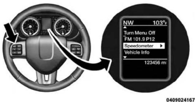
ElectronicVehicleInformationCenter(EVIC)
214 UNDERSTANDING YOUR INSTRUMENT PANEL
The EVIC Menu items consists of the following:
- Speedometer
- Vehicle Info
•Fuel Economy Info - Trip A
- Trip B
- Stop/Start Info (If Equipped)
• Air Suspension (If Equipped) - Trailer Tow
- Messages
•Screen Setup - Vehicle Settings (Not Equipped with a Uconnect® 5.0 & 8.4 radio)
The system allows the driver to select information by pushing the following EVIC Control buttons located on the left side of the steering wheel:

040971549
EVICControlButtons
UNDERSTANDING YOUR INSTRUMENT PANEL 215
- UPArrowButton

Push and release the UP arrow button to scroll upward through the main menu items.
- DOWNArrowButton

Push and release the DOWN arrow button to scroll downward through the main menu items.
•RIGHTArrowButton

Push and release the RIGHT arrow button to access/select the information screens or sub-menu screens of a main menu item. Push and hold the RIGHT arrow button for two seconds
to reset displayed/selected features that can be reset.
- LEFTArrowButton

Push and release the LEFT arrow button to return to the main menu, to exit the main menu push and release the UP or DOWN arrow to highlight Turn Menu Off, then push and re-
lease the RIGHT arrow.
216 UNDERSTANDING YOUR INSTRUMENT PANEL
Electronic Vehicle Information Center (EVIC) Displays — 3.5" Display

flowchart
graph TD
    1 --> 2
    2 --> 3
    3 --> 4
    4 --> 5
    5 --> 6
    6 --> 7
    7 --> 1
    1 --> 8
    8 --> 9
    9 --> 10
    10 --> 11
    11 --> 12
    12 --> 13
    13 --> 14
    14 --> 15
    15 --> 16
    16 --> 17
    17 --> 18
    18 --> 19
    19 --> 20
    20 --> 21
    21 --> 22
    22 --> 23
    23 --> 24
    24 --> 25
    25 --> 26
    26 --> 27
    27 --> 28
    28 --> 29
    29 --> 30
    30 --> 31
    31 --> 32
    32 --> 33
    33 --> 34
    34 --> 35
    35 --> 36
    36 --> 37
    37 --> 38
    38 --> 39
    39 --> 40
    40 --> 41
    41 --> 42
    42 --> 43
    43 --> 44
    44 --> 45
    45 --> 46
    46 --> 47
    47 --> 48
    48 --> 49
    49 --> 50
    50 --> 51
    51 --> 52
    52 --> 53
    53 --> 54
    54 --> 55
    55 --> 56
    56 --> 57
    57 --> 58
    58 --> 59
    59 --> 60
    60 --> 61
    61 --> 62
    62 --> 63
    63 --> 64
    64 --> 65
    65 --> 66
    66 --> 67
    67 --> 68
    68 --> 69
    69 --> 70
    70 --> 71
    71 --> 72
    72 --> 73
    73 --> 74
    74 --> 75
    75 --> 76
    76 --> 77
    77 --> 78
    78 --> 79
    79 --> 80
    80 --> 81
    81 --> 82
    82 --> 83
    83 --> 84
    84 --> 85
    85 --> 86
    86 --> 87
    87 --> 88
    88 --> 89
    89 --> 90
0409021772
The EVIC displays are located in the center portion of the cluster and consists of seven sections:
- CompassDisplay
Displays the current direction. For further information, refer to "Compass Settings" under "Customer Programmable Features — Uconnect® 5.0/8.4 Settings."
2.TemperatureDisplay
Displays the temperature in degrees Celsius or degrees Fahrenheit.
3.MainScreen
Displays main menu, sub-menus, settings.
4.EVICWhiteTelltales
5.EVICAmberTelltales
UNDERSTANDING YOUR INSTRUMENT PANEL 217
6.EVICRedTelltales
7. Audio/PhoneInformationAndSub-menuInformation
Whenever there are sub-menus available, the position within the sub-menu is shown here.
The main display area will normally display the main menu or the screens of a selected feature of the main menu. The main display area also displays "pop up" messages that consist of approximately 60 possible warning or information messages. These pop up messages fall into several categories:
- FiveSecondStoredMessages
When the appropriate conditions occur, this type of message takes control of the main display area for five seconds and then returns to the previous screen. Most of the messages of this type are then stored (as long as the condition that activated it remains active) and can be reviewed from the “Messages” main menu item. As long as there is a stored message, an "i" will be displayed in the EVIC's compass/outside temp line. Examples of this message type are "Right Front Turn Signal Lamp Out" and "Low Tire Pressure."
- UnstoredMessages
This message type is displayed indefinitely or until the condition that activated the message is cleared. Examples of this message type are “Turn Signal On” (if a turn signal is left on) and “Lights On” (if driver leaves the vehicle).
• UnstoredMessagesUntilRUN
These messages deal primarily with the Remote Start feature. This message type is displayed until the ignition is in the RUN state. Examples of this message type are "Remote Start Aborted - Door Ajar" and "Press Brake Pedal and Push Button to Start."
218 UNDERSTANDING YOUR INSTRUMENT PANEL
- FiveSecondUnstoredMessages
When the appropriate conditions occur, this type of message takes control of the main display area for five seconds and then returns to the previous screen. An example of this message type is “Automatic High Beams On.”
Oil Life Reset
Your vehicle is equipped with an engine oil change indicator system. The “Oil Change Required” message will display for approximately 10 seconds after a single chime has sounded, to indicate the next scheduled oil change interval. The engine oil change indicator system is duty cycle based, which means the engine oil change interval may fluctuate, dependent upon your personal driving style.
NOTE: Use the steering wheel controls for the following procedure(s)
VehiclesEquippedWithPassiveEntry
- Without pushing the brake pedal, push the ENGINE START/STOP button and cycle the ignition to the ON/RUN position (do not start the engine).
- Push and release the DOWNarrow button to scroll downward through the main menu to "Vehicle Info".
- Push and release the RIGHTarrow button to access the "OilLife" screen.
- Push and hold the RIGHTarrow button for one second to access the "OilLifeReset" screen.
- Push and release the DOWNarrow button to select "Yes", then push and release the RIGHTarrow button to select reset of the Oil Life.
- Push and release the Up arrow button to exit the EVIC screen.
VehiclesNotEquippedWithPassiveEntry
- Without pushing the brake pedal, cycle the ignition to the ON/RUN position (do not start the engine).
- Push and release the DOWNarrow button to scroll downward through the main menu to "Vehicle Info".
- Push and release the RIGHTarrow button to access the "OilLife" screen.
- Push and hold the RIGHTarrow button for one second to access the "OilLifeReset" screen.
- Push and release the DOWNarrow button to select "Yes", then push and release the RIGHTarrow button to select reset of the Oil Life.
- Push and release the Up arrow button to exit the EVIC screen.
NOTE: If the indicator message illuminates when you start the vehicle, the oil change indicator system did not reset. If necessary, repeat this procedure.
EVIC Messages
• Front Seatbelts Unbuckled
- Driver Seatbelt Unbuckled
• Passenger Seatbelt Unbuckled
•Service Airbag System
• Traction Control Off
- Washer Fluid Low
- Oil Pressure Low
- Oil Change Due
- Fuel Low
•Service Antilock Brake System
•Service Electronic Throttle Control
•Service Power Steering
220 UNDERSTANDING YOUR INSTRUMENT PANEL
• Cruise Off
• Cruise Ready
• Cruise Set To XXX MPH
- Tire Pressure Screen With Low Tire(s) "Inflate Tire to XX"
• Tire Pressure Information System (TPIS)
•Service Tire Pressure System
- Parking Brake Engaged
- Brake Fluid Low
•Service Electronic Braking System
•Engine Temperature Hot
- Battery Voltage Low
•Service Electronic Throttle Control
•Lights On
• Right Turn Signal Light Out
- Left Turn Signal Light Out
- Turn Signal On
- Sound Horn with Remote Lock: Off; 1st Press; 2nd Press
- Vehicle Not in Park
•Key in Ignition
•Key in Ignition Lights On
- Remote Start Active Key to Run
- Remote Start Active Push Start Button
- Remote Start Aborted Fuel Low
- Remote Start Aborted Too Cold
UNDERSTANDING YOUR INSTRUMENT PANEL 221
- Remote Start Aborted Door Open
- Remote Start Aborted Hood Open
- Remote Start Aborted Trunk Open
- Remote Start Aborted Time Expired
- Remote Start Disabled Start to Reset
•Service Airbag System
•Service Airbag Warning Light - Driver Seatbelt Unbuckled
- Passenger Seatbelt Unbuckled
•Front Seatbelts Unbuckled - Door Open
-
Doors Open
•Gear Not Available -
Shift Not Allowed
- Shift to Neutral then Drive or Reverse
•Automatic Unavailable Use Autostick Service Req.
• Transmission Getting Hot Press Brake
•Trans. Hot Stop Safely Shift to Park Wait to Cool
•Transmission Cool Ready to Drive - Trailer Brake Disconnected
•Service Transmission
•Service Shifter - Engage Park Brake to Prevent Rolling
• Transmission Too cold Idle with Engine On - Washer Fluid Low
- Autostop Duration – If Equipped
222 UNDERSTANDING YOUR INSTRUMENT PANEL
The Reconfigurable Telltales section is divided into the white telltales area on the right, yellow telltales in the middle, and red telltales on the left.
EVIC Red Telltales
This area will show reconfigurable red telltales. These telltales include:
•DoorAjar

This light will turn on to indicate that one or more doors may be ajar.
• OilPressureWarningLight
This telltale indicates low engine oil pressure. If the light turns on while driving, stop the vehicle and shut off the engine as soon as possible. A chime will sound when this light turns on.
Do not operate the vehicle until the cause is corrected. This light does not show how much oil is in the engine. The engine oil level must be checked under the hood.
• OilTemperatureWarningLight

This telltale indicates engine oil temperature is high. If the light turns on while driving, stop the vehicle and shut off the engine as soon as possible.
- ChargingSystemLight

This light shows the status of the electrical charging system. If the light stays on or comes on while g, turn off some of the vehicle's non-essential cal devices or increase engine speed (if at idle). If charging system light remains on, it means that the e is experiencing a problem with the charging h. OBTAIN SERVICE IMMEDIATELY. See an au-ed dealer.
UNDERSTANDING YOUR INSTRUMENT PANEL 223
If jump starting is required, refer to "Jump Starting Procedures" in "What To Do In Emergencies."
• ElectronicThrottleControl(ETC)Light

This light informs you of a problem with the Electronic Throttle Control (ETC) system. The light will come on when the ignition is first turned ON and remain on briefly as a bulb check. If the light does not come on during starting, have the system checked by an authorized dealer.
If a problem is detected, the light will come on while the engine is running. Cycle the ignition key when the vehicle has completely stopped and the shift lever is placed in the PARK position. The light should turn off.
If the light remains lit with the engine running, your vehicle will usually be drivable. However, see an authorized dealer for service as soon as possible. If the light is flashing when the engine is running, immediate service is required. You may experience reduced performance, an elevated/rough idle or engine stall and your vehicle may require towing.
•EngineTemperatureWarningLight
This light warns of an overheated engine condition. As temperatures rise and the gauge approaches H, this indicator will illuminate and a single chime will sound after reaching a set threshold. Further overheating will cause the temperature gauge to pass H, a continuous chime will occur until the engine is allowed to cool.
If the light turns on while driving, safely pull over and stop the vehicle. If the A/C system is on, turn it off. Also, shift the transmission into NEUTRAL and idle the vehicle. If the temperature reading does not return to normal, turn the engine off immediately and call for service. Refer to "If Your Engine Overheats" in "What To Do In Emergencies" for more information.
224 UNDERSTANDING YOUR INSTRUMENT PANEL
- TrailerBrakeDisconnectedWarningLight

This telltale is on when the Trailer Brake has been disconnected.
EVIC Yellow Telltales
This area will show reconfigurable yellow caution tell-tales. These telltales include:
- LowFuelTelltale

When the fuel level reaches approximately 3.0 gal (11.0 L) this light will turn on, and remain on until added.
•WindshieldWasherFluidLowIndicator

This telltale will turn on to indicate the wind-shield washer fluid is low.
- LowCoolantLevelIndicator

This telltale will turn on to indicate the vehicle coolant level is low.
• Transmission Temperature Warning Telltale

This telltale indicates that the transmission fluid temperature is running hot. This may occur with severe usage, such as trailer towing. If this telltale turns on, safely pull over and stop the then, shift the transmission into NEUTRAL and engine at idle or faster until the light turns off.
CAUTION!
ContinuousdrivingwiththeTransmissionTemperatureWarningLightilluminatedwilleventuallycauseseveretransmissiondamageortransmissionfailure.
WARNING!
If you continue operating the vehicle when the Transmission Temperature Warning Light is illuminated you could cause the fluid to oil over, come in contact with hot engine exhaust components and cause fire.
- LooseFuelFillerCap

This telltale will turn on to indicate that the fuel filler cap may be loose.
EVIC White Telltales
•ElectronicSpeedControlON

This light will turn on when the electronic speed control is ON. For further information, refer to "Electronic Speed Control" in "Understanding The Features Of Your Vehicle."
•ElectronicSpeedControlSET

This light will turn on when the electronic speed control is SET. For further information, refer to "Electronic Speed Control" in "Understanding The Features Of Your Vehicle."
• HillDescentControl-Ifequipped

This indicator will illuminate when Hill Descent Control (HDC) has been selected using the Hill Descent Control Switch., refer to "Electronic Brake Control" in "Starting And Operating."
226 UNDERSTANDING YOUR INSTRUMENT PANEL
EVIC Selectable Menu Items
Push and release the UP or DOWN arrow buttons until the desired Selectable Menu item is highlighted in the EVIC.
Speedometer
Push and release the UPor DOWNarrow button until the speedometer menu item is highlighted in the EVIC. Push and release the RIGHTarrow button to cycle the display between mph and km/h.
VehicleInfo
Push and release the UP or DOWN arrow button(s) until the Vehicle Info menu item is highlighted in the EVIC. Push and release the RIGHTarrow button to enter the sub-menus items of Vehicle Info. follow the directional prompts to access or reset any of the following Vehicle Info sub-menu items:
- Tire Pressure
- Coolant Temp
• Transmission Temp (Automatic only) - Oil Temp
- Oil Pressure
- Oil Life
- Battery Voltage
•Gauge Summary - Engine Hours
FuelEconomy
Push and release the UPor DOWNarrow button until the Fuel Economy menu item is highlighted. Push and Hold the RIGHTarrow button to reset Average Fuel Economy.
- Current Fuel
UNDERSTANDING YOUR INSTRUMENT PANEL 227
• Economy gauge
• Average Fuel Economy value
- Range to Empty
• Dual Fuel Tank levels — If Equipped
- Push and release the RIGHT arrow button to display the Fuel Tank Level submenu item. Your EVIC will display the fuel levels of the Front and Rear fuel tanks. The fuel is automatically transferred from the Rear tank to the Front tank based on both tank levels. Fuel transfer is complete once the Front Fuel Level is greater than the Rear Fuel Level.
TripA
Push and release the UPor DOWNarrow button until the Trip A menu item is highlighted in the EVIC. The Trip A information will display the following:
- Distance
• Average MPG
- Elapsed Time
Push and hold RIGHT arrow button to reset all information.
TripB
Push and release Up & Down arrow button until the Trip B menu item is highlighted in the EVIC. The Trip B information will display the following:
- Distance
• Average MPG - Elapsed Time
Push and hold the RIGHTarrow button to reset all the information.
228 UNDERSTANDING YOUR INSTRUMENT PANEL
TrailerTow
Push and release the UPor DOWNarrow button until the Trailer Tow menu item is highlighted. Push and release the RIGHT arrow button and the next screen will display the following trailer trip information:
- Trip (trailer specific) Distance
- Trailer Brake
- Output
•Type
•Gain
Push and hold the RIGHTarrow button to reset all the information.
EVICMessages
•Front Seatbelts Unbuckled
- Driver Seatbelt Unbuckled
• Passenger Seatbelt Unbuckled
•Service Airbag System
- Traction Control Off
- Washer Fluid Low
- Oil Pressure Low
- Oil Change Due
- Fuel Low
•Service Antilock Brake System
•Service Electronic Throttle Control
•Service Power Steering
• Cruise Off
• Cruise Ready
• Cruise Set To XXX MPH
UNDERSTANDING YOUR INSTRUMENT PANEL 229
- Tire Pressure Screen With Low Tire(s) "Inflate Tire to XX"
• Tire Pressure Information System (TPIS)
•Service Tire Pressure System - Parking Brake Engaged
- Brake Fluid Low
•Service Electronic Braking System
•Engine Temperature Hot - Battery Voltage Low
•Service Electronic Throttle Control
•Lights On
• Right Turn Signal Light Out -
Left Turn Signal Light Out
-
Turn Signal On
- Sound Horn with Remote Lock: Off; 1st Press; 2nd Press
- Vehicle Not in Park
•Key in Ignition
•Key in Ignition Lights On - Remote Start Active Key to Run
- Remote Start Active Push Start Button
- Remote Start Aborted Fuel Low
- Remote Start Aborted Too Cold
- Remote Start Aborted Door Open
- Remote Start Aborted Hood Open
- Remote Start Aborted Trunk Open
230 UNDERSTANDING YOUR INSTRUMENT PANEL
- Remote Start Aborted Time Expired
- Remote Start Disabled Start to Reset
•Service Airbag System
•Service Airbag Warning Light - Driver Seatbelt Unbuckled
• Passenger Seatbelt Unbuckled
•Front Seatbelts Unbuckled - Door Open
- Doors Open
•Gear Not Available - Shift Not Allowed
- Shift to Neutral then Drive or Reverse
• Automatic Unavailable Use Autostick Service Req.
• Transmission Getting Hot Press Brake
•Trans. Hot Stop Safely Shift to Park Wait to Cool
• Transmission Cool Ready to Drive
• Trailer Brake Disconnected
•Service Transmission
•Service Shifter
- Engage Park Brake to Prevent Rolling
• Transmission Too cold Idle with Engine On
- Washer Fluid Low
- Autostop Duration – If Equipped
The Reconfigurable Telltales section is divided into the white telltales area on the right, yellow telltales in the middle, and red telltales on the left.
ScreenSetup
Push and release the UPor DOWNarrow button until the Screen Setup menu item is highlighted in the EVIC. Push and release the RIGHTarrow button to enter the Screen Setup sub-menu. The Screen Setup feature allows you to change what information is displayed in the instrument cluster as well as the location that information is displayed.
VehicleSettings
Personal Settings allows the driver to set and recall features when the transmission is in PARK.
Push and release the UPand DOWNbutton until Settings displays in the EVIC.
Follow the prompts to display and set any of the following Vehicle Settings.
NOTE: Your vehicle may or may not be equipped with all the following settings.
| SettingNames | SettingNamesAbbreviated(Left SubmenuLayer) | Sub-Menus(RightSubmenuLayer) | |
| 1 Language Select Language English, Spanish, French, Italian, German, Dutch | |||
| 2 Units Units U.S.; Metric | |||
| 3 Park | Sense ParkSense | ●Notification — Sound Only; Sound & Display●Front Volume — Low; Medium; High●Rear Volume — Low; Medium; High | |
| 4 Tilt | Mirror in Reverse | Tilt Mirror in R On; Off | |
| 5 Rain | Sensing Wipers Auto Wipers On; Off | ||
| 6 Hill | Start Assist Hill Start Assist On; Off | ||
| 7 Headlights Off Delay | Lights Off Delay 0 seconds; 30 seconds; 60 seconds; 90 seconds | ||
| 8 | Illuminated Approach | Lights w/ Unlock | 0 seconds; 30 seconds; 60 seconds; 90 seconds |
| 9 | Headlights On with Wipers | Lights w/ Wipers | On; Off |
| 10 | Automatic Highbeams | Auto Highbeams | On; Off |
| 11 Flash Lights with Lock | Lights w/ Lock On; Off | ||
| 12 Auto Lock Doors Auto Lock | Doors On; Off | ||
| 13 Auto Unlock Doors Auto Unlock Doors On; Off | |||
| 14 Sound Horn with Remote Start | Horn w/ Rmt Start On; Off | ||
| 15 Sound Horn with Remote Lock | Horn w/ Rmt Lock On; Off | ||
| 16 Remote Unlock Sequence | Remote Unlock Driver Door; All Doors | ||
| 17 Key Fob Linked to Memory | Key in Memory On; Off | ||
| 18 | Passive Entry | Passive Entry | On; Off |
| 19 Remote StartComfort System | Rmt Start Comfort On; Off | ||
| 20 Easy Exit Seat Easy Exit Seat | On; Off | ||
| 21 Key-off Power Delay Power | Off Delay Off; 45 seconds; 5 minutes; 10 minutes | ||
| 22 Commercial Settings Commercial | Aux SwitchesPower Take-OffPIN Setup | ||
| 23 Air Suspension Display Alerts | Air Susp. Alerts All; Warnings Only | ||
| 24 | Aero Ride Height Mode | Aero Mode | On; Off |
| 25 | Tire/Jack Mode | Tire/Jack Mode | On; Off |
| 26 | Transport Mode Transport Mode | On; Off | |
| 27 Wheel Alignment Mode | Wheel Alignment On; Off | ||
| 28 Horn w/ Remote Lower | Horn w/ Rmt Lwr On; Off | ||
| 29 Lights w/ Remote Lower | Lights w/ Rmt Lwr On; Off | ||
| 30 Trailer Select Trailer Select | Trailer 1; Trailer 2; Trailer 3; Trailer 4 | ||
| 31 Brake Type Brake Type Light | Electric; Heavy Electric; Light EOH; Heavy EOH | ||
236 UNDERSTANDING YOUR INSTRUMENT PANEL
| SettingNames | SettingNamesAbbreviated(Left SubmenuLayer) | Sub-Menus(RightSubmenuLayer) | |
| 32 | Trailer Name Trailer Name | • Trailer # (# is equal to slot position)• Boat• Car• Cargo• Dump• Equipment• Flatbed• Gooseneck• Horse• Tag• Motorcycle• Snowmobile• Travel• Utility• 5th Wheel | |
| 33 | Compass Variance Compass | Var 1-15 increments of 1 | |
| 34 | Calibrate Compass Compass | Cal Cancel; Calibrate | |
| 35 | Fuel Saver Display Fuel Saver | On; Off |
TurnMenuOFF
Push and release the RIGHTarrow button to exit the main menu.
Push and release any EVIC control button to enter the EVIC main menu again.
238 UNDERSTANDING YOUR INSTRUMENT PANEL
DRIVER INFORMATION DISPLAY (DID)
The Driver Information Display (DID) features a driver-interactive display that is located in the instrument cluster.

DriverInformationDisplay(DID)
The DID Menu items consists of the following:
• Digital Speedometer
- Vehicle Info
- Fuel Economy Info
- Trip A
- Trip B
- Trailer Tow
•Audio
- Stored Messages
- Screen Setup
- Vehicle Settings (Not Equipped with a Uconnect® 5.0 & 8.4 radio)
The system allows the driver to select information by pushing the following buttons mounted on the steering wheel:
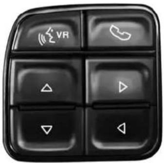
DIDControls
040971549
UNDERSTANDING YOUR INSTRUMENT PANEL 239
-UPArrowButton

Push and release the UParrow button to scroll upward through the main menu and submenus.
- DOWNArrowButton

Push and release the DOWNarrow button to scroll downward through the main menu and submenus.
•RIGHTArrowButton

Push and release the RIGHTarrow button to access/select the information screens or sub-menu screens of a main menu item. Push and hold the RIGHT arrow button for two seconds isplayed/selected features that can be reset.
240 UNDERSTANDING YOUR INSTRUMENT PANEL
- LEFTArrowButton

Push and release the LEFTarrow button to return to the main menu from an info screen or submenu item.
Driver Information Display (DID) Displays
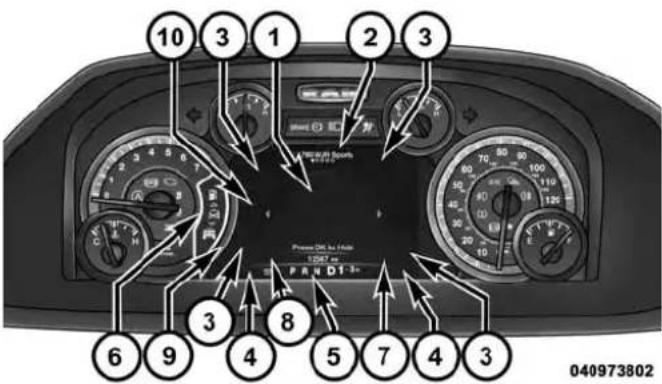
The DID displays are located in the center portion of the cluster and consists of eight sections:
UNDERSTANDING YOUR INSTRUMENT PANEL 241
- Main Screen — The inner ring of the display will illuminate in grey under normal conditions, yellow for non critical warnings, red for critical warnings, and white for on demand information.
- Audio / Phone Information and Sub-menu Information — Whenever there are sub-menus available, the position within the sub-menus is shown here.
- Selectable Information (Compass, Temp, Range to Empty, Trip A, Trip B, Average MPG, Trailer Trip (distance only), Trailer Brake Gain)
- Telltales/Indicators
- Shift Lever Status (PRNDL)
- Selectable Menu Icons
- Air Suspension Status – If Equipped
-
4WD Status
-
Selectable Gauge 2 (Trans Temp, Oil Temp, Oil Life, Trailer Brake, Current MPG)
-
Selectable Gauge 1 (Trans Temp, Oil Temp, Oil Life, Trailer Brake, Current MPG)
The main display area will normally display the main menu or the screens of a selected feature of the main menu. The main display area also displays “pop up” messages that consist of approximately 60 possible warning or information messages. These pop up messages fall into several categories:
- FiveSecondStoredMessages
When the appropriate conditions occur, this type of message takes control of the main display area for five seconds and then returns to the previous screen. Most of the messages of this type are then stored (as long as the condition that activated it remains active) and can be reviewed from the "Messages" main menu item. As long
242 UNDERSTANDING YOUR INSTRUMENT PANEL
as there is a stored message, an "i" will be displayed in the DID's compass/outside temp line. Examples of this message type are "Right Front Turn Signal Lamp Out" and "Low Tire Pressure."
- UnstoredMessages
This message type is displayed indefinitely or until the condition that activated the message is cleared. Examples of this message type are "Turn Signal On" (if a turn signal is left on) and "Lights On" (if driver leaves the vehicle).
• UnstoredMessagesUntilRUN
These messages deal primarily with the Remote Start feature. This message type is displayed until the ignition is in the RUN state. Examples of this message type are "Remote Start Aborted - Door Ajar" and "Press Brake Pedal and Push Button to Start."
- FiveSecondUnstoredMessages
When the appropriate conditions occur, this type of message takes control of the main display area for five seconds and then returns to the previous screen. An example of this message type is “Automatic High Beams On.”
Oil Life Reset
Your vehicle is equipped with an engine oil change indicator system. The “Oil Change Required” message will flash in the DID display for approximately 10 seconds after a single chime has sounded, to indicate the next scheduled oil change interval. The engine oil change indicator system is duty cycle based, which means the engine oil change interval may fluctuate, dependent upon your personal driving style.
NOTE: Use the steering wheel DID controls for the following procedure(s).
VehiclesEquippedWithPassiveEntry
- Without pushing the brake pedal, push the ENGINE START/STOP button and cycle the ignition to the ON/RUN position (do not start the engine).
- Push and release the DOWNarrow button to scroll downward through the main menu to "Vehicle Info."
- Push and release the RIGHTarrow button to access the "OilLife" screen.
- Push and hold the RIGHTarrow button for one second to access the "OilLifeReset" screen.
- Push and release the DOWNarrow button to select "Yes," then push and release the RIGHTarrow button to select reset of the Oil Life.
- Push and release the Uparrow button to exit the DID screen.
VehiclesNotEquippedWithPassiveEntry
- Without pushing the brake pedal, cycle the ignition to the ON/RUN position (do not start the engine).
- Push and release the DOWNarrow button to scroll downward through the main menu to "Vehicle Info."
- Push and release the RIGHTarrow button to access the "OilLife" screen.
- Push and hold the RIGHTarrow button for one second to access the "OilLifeReset" screen.
- Push and release the DOWNarrow button to select "Yes," then push and release the RIGHTarrow button to select reset of the Oil Life.
- Push and release the Uparrow button to exit the DID screen.
244 UNDERSTANDING YOUR INSTRUMENT PANEL
NOTE: If the indicator message illuminates when you start the vehicle, the oil change indicator system did not reset. If necessary, repeat this procedure.
DID Messages
•Front Seatbelts Unbuckled
- Driver Seatbelt Unbuckled
• Passenger Seatbelt Unbuckled
•Service Airbag System
- Traction Control Off
- Washer Fluid Low
- Oil Pressure Low
- Oil Change Due
- Fuel Low
•Service Antilock Brake System
•Service Electronic Throttle Control
•Service Power Steering
• Cruise Off
• Cruise Ready
• Cruise Set To XXX MPH
- Tire Pressure Screen With Low Tire(s) "Inflate Tire to XX"
•Tire Pressure Information System (TPIS)
•Service Tire Pressure System
- Parking Brake Engaged
- Brake Fluid Low
•Service Electronic Braking System
- Engine Temperature Hot
UNDERSTANDING YOUR INSTRUMENT PANEL 245
- Battery Voltage Low
•Service Electronic Throttle Control
•Lights On
• Right Turn Signal Light Out - Left Turn Signal Light Out
- Turn Signal On
- Sound Horn with Remote Lock: Off; 1st Press; 2nd Press
- Vehicle Not in Park
•Key in Ignition
•Key in Ignition Lights On - Remote Start Active Key to Run
-
Remote Start Active Push Start Button
-
Remote Start Aborted Fuel Low
- Remote Start Aborted Too Cold
- Remote Start Aborted Door Open
- Remote Start Aborted Hood Open
- Remote Start Aborted Trunk Open
- Remote Start Aborted Time Expired
- Remote Start Disabled Start to Reset
•Service Airbag System
•Service Airbag Warning Light - Driver Seatbelt Unbuckled
- Passenger Seatbelt Unbuckled
• Front Seatbelts Unbuckled - Door Open
246 UNDERSTANDING YOUR INSTRUMENT PANEL
- Doors Open
•Gear Not Available - Shift Not Allowed
- Shift to Neutral then Drive or Reverse
• Automatic Unavailable Use Autostick Service Req.
• Transmission Getting Hot Press Brake
•Trans. Hot Stop Safely Shift to Park Wait to Cool
• Transmission Cool Ready to Drive
• Trailer Brake Disconnected
•Service Transmission
•Service Shifter - Engage Park Brake to Prevent Rolling
• Transmission Too cold Idle with Engine On
- Washer Fluid Low
- Autostop Duration – If Equipped
The Reconfigurable Telltales section is divided into the white telltales area on the right, yellow telltales in the middle, and red telltales on the left.
DID Red Telltales
This area will show reconfigurable red telltales. These telltales include:
- DoorAjar
This light will turn on to indicate that one or more doors may be ajar.
UNDERSTANDING YOUR INSTRUMENT PANEL 247
• OilPressureWarningLight

This telltale indicates low engine oil pressure. If the light turns on while driving, stop the vehicle and shut off the engine as soon as possible. A chime will sound when this light turns on.
Do not operate the vehicle until the cause is corrected. This light does not show how much oil is in the engine. The engine oil level must be checked under the hood.
• OilTemperatureWarningLight

This telltale indicates engine oil temperature is high. If the light turns on while driving, stop the vehicle and shut off the engine as soon as possible.
- ChargingSystemLight

This light shows the status of the electrical charging system. If the light stays on or comes on while g, turn off some of the vehicle's non-essential
electrical devices or increase engine speed (if at idle). If the charging system light remains on, it means that the vehicle is experiencing a problem with the charging system. OBTAIN SERVICE IMMEDIATELY. See an authorized dealer.
If jump starting is required, refer to "Jump Starting Procedures" in "What To Do In Emergencies."
•ElectronicThrottleControl(ETC)Light

This light informs you of a problem with the Electronic Throttle Control (ETC) system. The light will come on when the ignition is first turned ON and remain on briefly as a bulb check. If the light does not come on during starting, have the system checked by an authorized dealer.
If a problem is detected, the light will come on while the engine is running. Cycle the ignition key when the vehicle has completely stopped and the shift lever is placed in the PARK position. The light should turn off.
248 UNDERSTANDING YOUR INSTRUMENT PANEL
If the light remains lit with the engine running, your vehicle will usually be drivable. However, see an authorized dealer for service as soon as possible. If the light is flashing when the engine is running, immediate service is required. You may experience reduced performance, an elevated/rough idle or engine stall and your vehicle may require towing.
•EngineTemperatureWarningLight

This light warns of an overheated engine condition. As temperatures rise and the gauge approaches H, this indicator will illuminate and a single chime will sound after reaching a set threshold. Further overheating will cause the temperature gauge to pass H, a continuous chime will occur until the engine is allowed to cool.
If the light turns on while driving, safely pull over and stop the vehicle. If the A/C system is on, turn it off. Also, shift the transmission into NEUTRAL and idle the vehicle. If the temperature reading does not return to normal, turn the engine off immediately and call for service. Refer to "If Your Engine Overheats" in "What To Do In Emergencies" for more information.
- TrailerBrakeDisconnectedWarningLight

This telltale is on when the Trailer Brake has been disconnected.
DID Yellow Telltales
This area will show reconfigurable yellow caution tell-tales. These telltales include:
- LowFuelTelltale

When the fuel level reaches approximately 3.0 gal (11.0 L), this light will turn on, and remain on until added.
UNDERSTANDING YOUR INSTRUMENT PANEL 249
•WindshieldWasherFluidLowIndicator

This telltale will turn on to indicate the wind-shield washer fluid is low.
- LowCoolantLevelIndicator

This telltale will turn on to indicate the vehicle coolant level is low.
• Transmission Temperature Warning Telltale

This telltale indicates that the transmission fluid temperature is running hot. This may occur with severe usage, such as trailer towing. If this telltale turns on, safely pull over and stop the vehicle. Then, shift the transmission into NEU-TRAL and run the engine at idle or faster until the light turns off.
CAUTION!
ContinuousdrivingwiththeTransmissionTemperatureWarningLightilluminatedwilleventuallycauseseveretransmissiondamageortransmissionfailure.
WARNING!
If you continue operating the vehicle when the Transmission Temperature Warning Light is illuminated you could cause the fluid to oil over, come in contact with hot engine exhaust components and cause a fire.
- LooseFuelFillerCap

This telltale will turn on to indicate that the fuel filler cap may be loose.
DID White Telltales
•ElectronicSpeedControlReady

This light will turn on when the electronic speed control is ON. For further information, refer to "Electronic Speed Control" in "Understanding The Features Of Your Vehicle."
DID Selectable Menu Items
Push and release the UPor DOWNarrow buttons until the desired Selectable Menu icon/title is highlighted in the DID.
DigitalSpeedometer

Push and release the UPor DOWNarrow button until the Digital display icon is highlighted in the DID. Push and release the
RIGHTarrow button to change the display
between mph and km/h.
VehicleInfo

Push and release the UPor DOWNarrow button until the Vehicle Info icon is highlighted in the DID. Push and release the RIGHT arrow button to enter the submenus items of Vehicle
Info. follow the directional prompts to access or reset any of the following Vehicle Info submenu items:
TirePressureInformationSystem(3500SeriesHeavy DutyRamTrucks)
Push and release the UPor DOWNarrow button until "Tire Pressure" is highlighted in the DID. Push and release the RIGHT arrow button and one of the following will be displayed:
A vehicle ICON is displayed with the tire pressure values in each corner of the ICON.
If the Tire Pressure system requires service, "Service Tire Pressure System" is displayed.
- Tire PSI is an information only function and cannot be reset.
- Refer to the "Tire Pressure Information System (TPIS) under "Starting and Operating" for further information.
- TransmissionTemperature-AutomaticTransmissionOnly
- OilTemperature
•OilLife - BatteryVoltage—IfEquipped
• GaugeSummary: - Coolant Temperature
- Transmission Temperature (automatic only)
- Oil Temperature
- Oil Pressure
- EngineHours
FuelEconomy

Push and release the UPor DOWNarrow button until the Fuel Economy Menu icon/title is highlighted.
Submenuitem:
- Range
• Current MPG or L/100 km
• Average MPG or L/100 km - To reset the following features (Range, Current MPG or L/100 km, or Average MPG / L/100 km), push hold the RIGHTarrow button till features are reset.
• Dual Fuel Tank levels — If Equipped
252 UNDERSTANDING YOUR INSTRUMENT PANEL
- Push and release the RIGHTarrow button to display the Fuel Tank Level submenu item. Your DID will display the fuel levels of the Front and Rear fuel tanks.
- The fuel is automatically transferred from the Rear tank to the Front tank based on both tank levels. Fuel transfer is complete once the Front Fuel Level is greater than the Rear Fuel Level.
TripA

Push and release the UPor DOWNarrow button until the Trip A icon/title is highlighted in the DID. The Trip A information will display the following:
• Distance MI or km
• Average MPG or L/100 km
• Average MPH or km/h
- Elapsed Time
Hold the RIGHTarrow button to reset all the information.
Push the DOWNarrow button to enter Trip B.
TripB

The Trip B information will display the following:
- Distance MI or km
• Average MPG or L/100 km
• Average MPH or km/h - Elapsed Time
Hold the RIGHTarrow button to reset all the information.
TrailerTow

Push and release the UPor DOWNarrow button until the Trailer Tow icon is highlighted. Push and release the RIGHT arrow button and the next screen will display the following
trailer trip information:
- Trailer Trip
- Trailer Brake
Audio
Push and release the UPor DOWNarrow button until the Audio display icon is highlighted in the DID. Push and release the RIGHTarrow button to display the active source.
StoredMessages

Push and release the UP arrow button until the Messages display icon is highlighted in the DID. This feature shows the number of stored warning messages. Pushing the RIGHTarrow
button will allow you to see what the stored messages are.
ScreenSetup
Push and release the UPor DOWNarrow button until the Screen Setup display icon is highlighted in the DID. Push and release the RIGHT arrow button to enter the Screen Setup
submenu. The Screen Setup feature allows you to change what information is displayed in the instrument cluster as well as the location that information is displayed.
254 UNDERSTANDING YOUR INSTRUMENT PANEL
VehiclesSettings(Customer-Programmable Features)

NOTE: This feature is only available on 5.0 and 8.4 Uconnect® Radios
Personal Settings allows the driver to set and recall features when the transmission is in PARK.
Push and release the UPand DOWNbutton until Personal Settings displays in the DID.
Follow the prompts to display and set any of the following Personal Settings.
NOTE: Your vehicle may or may not be equipped with all the following settings.
| SettingNames | SettingNamesAbbreviated (LeftSubmenuLayer) | Sub-Menus (RightSubmenuLayer) | |
| 1 Language Select Language English, Spanish, French, Italian, | German, Dutch | ||
| 2 Units Units U.S.; Metric | |||
| 3 Park | Sense ParkSense | • Notification — Sound Only;Sound & Display• Front Volume — Low;Medium; High• Rear Volume — Low;Medium; High | |
| 4 Tilt | Mirror in Reverse Tilt Mirror in R On; Off | ||
| 5 Rain | Sensing Wipers Auto Wipers On; Off | ||
| 6 Hill | Start Assist Hill Start Assist | On; Off | |
| 7 | Headlights Off Delay | Lights Off Delay | 0 seconds; 30 seconds;60 seconds; 90 seconds |
| 8 | Illuminated Approach | Lights w/ Unlock | 0 seconds; 30 seconds;60 seconds; 90 seconds |
| 9 | Headlights On with Wipers | Lights w/ Wipers | On; Off |
| 10 | Automatic Highbeams | Auto Highbeams | On; Off |
| 11 Flash Lights with Lock Lights w/ Lock | On; Off | ||
| 12 Auto Lock Doors Auto Lock Doors On; | Off | ||
| 13 Auto Unlock Doors Auto Unlock Doors | On; Off | ||
| 14 Sound Horn with Remote Start Horn w/ Rmt Start On; Off | |||
| 15 Sound Horn with Remote Lock Horn w/ Rmt Lock On; Off | |||
| 16 | Remote Unlock Sequence | Remote Unlock | Driver Door; All Doors |
| 17 | Key Fob Linked to Memory | Key in Memory | On; Off |
| 18 | Passive Entry | Passive Entry | On; Off |
| 19 | Remote Start Comfort System | Rmt Start Comfort | On; Off |
| 20 | Easy Exit Seat | Easy Exit Seat | On; Off |
| 21 | Key-off Power Delay | Power Off Delay | Off; 45 seconds; 5 minutes;10 minutes |
| 22 Commercial Settings Commercial | Aux SwitchesPower Take-OffPIN Setup | ||
| 23 Air Suspension Display Alerts Air Susp. Alerts All;Warnings Only | |||
| 24 Aero Ride Height Mode Aero Mode On; Off | |||
| 25 Tire/Jack Mode Tire/Jack Mode On; Off | |||
| 26 | Transport Mode | Transport Mode | On; Off |
| 27 | Wheel Alignment Mode | Wheel Alignment | On; Off |
| 28 | Horn w/ Remote Lower | Horn w/ Rmt Lwr | On; Off |
| 29 | Lights w/ Remote Lower | Lights w/ Rmt Lwr | On; Off |
| 30 | Trailer Select | Trailer Select | Trailer 1; Trailer 2; Trailer 3; Trailer 4 |
| 31 | Brake Type | Brake Type | Light Electric; Heavy Electric; Light EOH; Heavy EOH |
258 UNDERSTANDING YOUR INSTRUMENT PANEL
| SettingNames | SettingNamesAbbreviated (LeftSubmenuLayer) | Sub-Menus (RightSubmenuLayer) | |
| 32 Trailer Name Trailer Name | Trailer # (# is equal to slot position)BoatCarCargoDumpEquipmentFlatbedGooseneckHorseTagMotorcycleSnowmobileTravelUtility5th Wheel | ||
| 33 | Compass Variance Compass Var 1-15 increments of 1 | ||
| 34 | Calibrate Compass Compass Cal Cancel; Calibrate | ||
| 35 | Fuel Saver Display Fuel Saver On; Off | ||
| 36 | Park Assist Front Chime Volume | Park Assist Front Chime Volume | On; Off |
| 37 | Park Assist Rear Chime Volume Park Assist Rear Chime Volume On; Off |
Uconnect® SETTINGS
The Uconnect® system uses a combination of buttons on the touchscreen and buttons on the faceplate located on the center of the instrument panel that allows you to access and change the customer programmable features. Many features can vary by vehicle.
260 UNDERSTANDING YOUR INSTRUMENT PANEL

Uconnect®5.0ButtonsOnTheTouchscreenAndButtons OnTheFaceplate
1 — Uconnect® Buttons On The Touchscreen
2 — Uconnect® Buttons On The Faceplate

Uconnect®8.4A/8.4ANButtonsOnTheTouchscreenAnd ButtonsOnTheFaceplate
1 — Uconnect® Buttons On The Touchscreen
2 — Uconnect® Buttons On The Faceplate
Buttons On The Faceplate
Buttons on the faceplate are located below the Uconnect® system in the center of the instrument panel. In addition, there is a Scroll/Enter control knob located on the right side of the Climate Controls in the center of the instrument panel. Turn the control knob to scroll through menus and change settings (i.e., 30, 60, 90), push the center of the control knob one or more times to select or change a setting (i.e., ON, OFF).
Your Uconnect® system may also have Screen Off and Back buttons located below the Uconnect® system.
Push the Screen Off button to turn off the Uconnect® touchscreen. Push the Screen Off button a second time to turn the touchscreen on.
Push the Back button to exit out of a Menu or certain option on the Uconnect® system.
Buttons On The Touchscreen
Buttons on the touchscreen are accessible on the Uconnect® display.
CustomerProgrammableFeatures—Uconnect® 5.0/8.4Settings
Push the + MORE button on the faceplate (Uconnect® 5.0) or the "Apps" button on the touchscreen (Uconnect® 8.4), then press the "Settings" button on the touchscreen to display the Setting menu screen. In this mode the Uconnect® system allows you to access programmable features that may be equipped such as Display, Clock, Safety & Driving Assistance, Lights, Doors & Locks, Auto-On Comfort & Remote Start, Engine Off Operation, Compass Settings, Audio, Phone/Bluetooth® and SiriusXM Setup.
NOTE: Only one touchscreen area may be selected at a time.
262 UNDERSTANDING YOUR INSTRUMENT PANEL
When making a selection, press the button on the touchscreen to enter the desired mode. Once in the desired mode, press and release the preferred setting until a check-mark appears next to the setting, showing that setting has been selected. Once the setting is complete, either press the "Back Arrow" button on the touchscreen or the BACK button on the faceplate to return to the previous menu or press the "X" button on the touchscreen to close out of the settings screen. Pressing the "Up" or "Down" arrow buttons on the touchscreen on the right side of the screen will allow you to toggle up or down through the available settings.
Display
After pressing the "Display" button on the touchscreen the following settings will be available.
- DisplayMode
When in this display you may select one of the auto display settings. To change Mode status, select from
"Day," "Night" or "Auto" until a check-mark appears next to the setting, showing that setting has been selected. Then press the arrow back button on the touchscreen.
NOTE: When Day or Night is selected for the Display Mode, the usage of the Parade Mode feature will cause the radio to activate the Display Brightness Day control even though the headlights are on.
- DisplayBrightnessWithHeadlightsON
When in this display, you may select the brightness with the headlights on. Adjust the brightness with the "+" and "-" setting buttons on the touchscreen or by selecting any point on the scale between the "+" and "-" buttons on the touchscreen. Then press the arrow back button on the touchscreen.
NOTE: To make changes to the "Display Brightness with Headlights ON" setting, the headlights must be on and the interior dimmer switch must not be in the "party" or "parade" positions.
- DisplayBrightnessWithHeadlightsOFF
When in this display, you may select the brightness with the headlights off. Adjust the brightness with the "+" and "-" setting buttons on the touchscreen or by selecting any point on the scale between the "+" and "-" buttons on the touchscreen. Then press the arrow back button on the touchscreen.
NOTE: To make changes to the "Display Brightness with Headlights OFF" setting, the headlights must be off and the interior dimmer switch must not be in the "party" or "parade" positions.
- SetTheme
This feature will allow you to choose a background theme for the display screen. The theme will change the background color, highlight color, and button color of the display screen. Press the "Set Theme" button on the touchscreen and select one of the pre-configured themes available.
- SetLanguage
When in this display, you may select one of multiple languages (English / Français / Español) for all display nomenclature, including the trip functions and the navigation system (if equipped). Press the Set Language button on the touchscreen, then press the desired language button on the touchscreen until a check-mark appears next to the language, showing that setting has been selected. Press the back arrow button on the touchscreen to return to the previous menu.
264 UNDERSTANDING YOUR INSTRUMENT PANEL
- Units
When in this display, you may select to have the Driver Information Display (DID), odometer, and navigation system (if equipped) changed between US and Metric units of measure. Press "US" or "Metric" until a checkmark appears next to the setting, showing that setting has been selected. Press the back arrow button on the touchscreen to return to the previous menu.
- TouchscreenBeep
When in this display, you may turn on or shut off the sound heard when a touchscreen button (button on the touchscreen) is pressed. Press the "Touchscreen Beep" button on the touchscreen until a check-mark appears next to the setting, showing that setting has been selected. Press the back arrow button on the touchscreen to return to the previous menu.
- NavigationTurn-By-TurnInCluster—IfEquipped
When this feature is selected, the turn-by-turn directions will appear in the display as the vehicle approaches a designated turn within a programmed route. To make your selection, press the "Navigation Turn-By-Turn In Cluster" button on the touchscreen, until a check-mark appears next to the setting, showing that setting has been selected. Press the back arrow button on the touchscreen to return to the previous menu.
- ControlsScreenTime-Out—IfEquipped
When this feature is selected, the Controls Screen will stay open for five seconds before the screen times out. With the feature deselected, the screen will stay open until it is manually closed. Press the “Controls Screen Time-Out” button on the touchscreen, until a check-mark appears next to the setting, showing that setting has been selected. Press the back arrow button on the touchscreen to return to the previous menu.
UNDERSTANDING YOUR INSTRUMENT PANEL 265
•FuelSaverDisplay—IfEquipped
This feature will allow you to enable fuel saver mode and will be displayed in the DID. Press the "Fuel Saver Display" button on the touchscreen, until a check-mark appears next to the setting, showing that setting has been selected. Press the back arrow button on the touchscreen to return to the previous menu.
Clock
After pressing the "Clock" button on the touchscreen the following settings will be available:
- SyncTimeWithGPS
This feature will allow you to automatically have the radio set the time. To change the Sync Time setting, press the "Sync with GPS Time" button on the touchscreen until a check-mark appears next to the setting, showing that setting has been selected. Press the back arrow button on the touchscreen to return to the previous menu, or push the back button on the faceplate.
- SetTimeHours
This feature will allow you to adjust the hours. The "Sync with GPS Time" button on the touchscreen must be unchecked. To make your selection, press the "+" or "-" buttons on the touchscreen to adjust the hours up or down. Press the back arrow button on the touchscreen to return to the previous menu or press the" X" button on the touchscreen to close out of the settings screen.
- SetTimeMinutes
This feature will allow you to adjust the minutes. The "Sync with GPS Time" button on the touchscreen must be unchecked. To make your selection, press the "+" or "-" buttons on the touchscreen to adjust the minutes up or down. Press the back arrow button on the touchscreen to return to the previous menu or press the "X" button on the touchscreen to close out of the settings screen.
266 UNDERSTANDING YOUR INSTRUMENT PANEL
- TimeFormat
This feature will allow you to select the time format display setting. Press the "Time Format" button on the touchscreen until a check-mark appears next to the 12hrs or 24hrs setting, showing that setting has been selected. Press the back arrow button on the touchscreen to return to the previous menu, or push the back button on the faceplate.
• ShowTimeInStatusBar—IfEquipped
This feature will allow you to turn on or shut off the digital clock in the status bar. To change the Show Time Status setting press the "Show Time in Status Bar" button on the touchscreen until a check-mark appears next to setting, indicating that the setting has been selected. To return to the previous menu, press the back arrow button on the touchscreen, or push the back button on the faceplate.
Safety&DrivingAssistance
After pressing the "Safety & Driving Assistance" button on the touchscreen the following settings will be available.
- TiltMirrorsInReverse
When this feature is selected, the outside sideview mirrors will tilt downward when the ignition is in the RUN position and the transmission shift lever is in the REVERSE position. The mirrors will move back to their previous position when the transmission is shifted out of REVERSE. To make your selection, press the "Tilt Mirrors In Reverse" button on the touchscreen, until a checkmark appears next to setting, showing that setting has been selected. Press the back arrow button on the touchscreen to return to the previous menu.
UNDERSTANDING YOUR INSTRUMENT PANEL 267
•ParkView®BackupCamera
Your vehicle may be equipped with the ParkView® Rear Back Up Camera that allows you to see an on-screen image of the rear surroundings of your vehicle whenever the shift lever is put into REVERSE. The image will be displayed on the radio touchscreen display along with a caution note to "check entire surroundings" across the top of the screen. After five seconds, this note will disappear. The ParkView® camera is located on the rear of the vehicle above the rear License plate. To make your selection, press the "ParkView® Backup Camera" button on the touchscreen, until a check-mark appears next to the setting, indicating that the setting had been selected. Press the back arrow button on the touchscreen to return to the previous menu.
- ParkView®CameraDelay
When this feature is enabled, it will allow the ParkView Backup Camera display to remain on while in drive for
up to 10 seconds, or 8 mph. To make your selection, press the "ParkView® Backup Camera Delay" button on the touchscreen, until a check-mark appears next to the setting, indicating that the setting had been selected. Press the back arrow button on the touchscreen to return to the previous menu.
- ParkView®BackupCameraActiveGuidelines
Your vehicle may be equipped with the ParkView® Rear Back Up Camera Active Guidelines that allows you to see Active (Dynamic) Guidelines which deflect with steering wheel angle over the ParkView Back up Camera display whenever the shift lever is put into REVERSE. The image will be displayed on the radio touchscreen display along with a caution note to "check entire surroundings" across the top of the screen. After five seconds, this note will disappear. To make your selection, press the "ParkView® Backup Camera Active Guidelines" button on the touchscreen, until a check-mark appears next to the setting,
268 UNDERSTANDING YOUR INSTRUMENT PANEL
indicating that the setting had been selected. Press the back arrow button on the touchscreen to return to the previous menu.
• RainSensingAutoWipers
When this feature is selected, the system will automatically activate the windshield wipers if it senses moisture on the windshield. To make your selection, press the "Rain Sensing" button on the touchscreen, until a checkmark appears next to the setting, showing that setting has been selected. Press the back arrow button on the touchscreen to return to the previous menu.
• HillStartAssist—IfEquipped
When this feature is selected, the Hill Start Assist (HSA) system is active. Refer to "Electronic Brake Control System" in "Starting And Operating" for system function and operating information. To make your selection, press the "Hill Start Assist" button on the touchscreen, until a check-mark appears next to the setting, showing that the setting has been selected. Press the back arrow button on the touchscreen to return to the previous menu.
Lights
After pressing the "Lights" button on the touchscreen the following settings will be available:
•HeadlightIlluminationOnApproach
When this feature is selected, the headlights will activate and remain on for 0, 30, 60, or 90 seconds when the doors are unlocked with the Remote Keyless Entry (RKE) transmitter. To change the Illuminated Approach status, press the "+" or "-" button on the touchscreen to select your desired time interval. Press the back arrow button on the touchscreen to return to the previous menu.
•HeadlightsWithWipers—IfEquipped
When this feature is selected, and the headlight switch is in the AUTO position, the headlights will turn on approximately 10 seconds after the wipers are turned on.
The headlights will also turn off when the wipers are turned off, if they were turned on by this feature. To make your selection, press the "Headlights With Wipers" button on the touchscreen, until a check-mark appears next to the setting, showing that setting has been selected. Press the back arrow button on the touchscreen to return to the previous menu.
• AutoDimHighBeams—IfEquipped
When this feature is selected, the high beam headlights will deactivate automatically under certain conditions. To make your selection, press the "Auto High Beams" button on the touchscreen, until a check-mark appears next to the setting, showing that setting has been selected. Press the back arrow button on the touchscreen to return to the previous menu. Refer to "Automatic High Beam — If Equipped" in "Understanding The Features Of Your Vehicle" for further information.
- FlashLampsWithLock
When this feature is selected, the exterior lights will flash when the doors are locked or unlocked with the Remote Keyless Entry (RKE) transmitter. This feature may be selected with or without the Sound Horn on Lock feature selected. To make your selection, press the "Flash Lamps with Lock" button on the touchscreen, until a check-mark appears next to the setting, showing that setting has been selected. Press the back arrow button on the touchscreen to return to the previous menu.
Doors&Locks
After pressing the "Doors & Locks" button on the touchscreen the following settings will be available:
•AutoUnlockOnExit
When this feature is selected, all doors will unlock when the vehicle is stopped, the transmission is in the PARK or NEUTRAL position and the driver's door is opened.
270 UNDERSTANDING YOUR INSTRUMENT PANEL
To make your selection, press the "Auto Unlock On Exit" button on the touchscreen, until a check-mark appears next to the setting, showing that the setting has been selected. Press the back arrow button on the touchscreen to return to the previous menu.
- SoundHornWithLock
When this feature is selected, the horn will sound when the door locks are activated. To make your selection, press the "Sound Horn With Lock" button on the touchscreen, until a check-mark appears next to the setting, showing that the setting has been selected. Press the back arrow button on the touchscreen to return to the previous menu.
• SoundHornWithRemoteStart
When this feature is selected, the horn will sound when the remote start is activated. To make your selection, press the "Sound Horn With Remote Start" button on the touchscreen, until a check-mark appears next to the setting, showing that the setting has been selected. Press the back arrow button on the touchscreen to return to the previous menu.
- 1stPushOfKeyFobUnlocks
When 1st Push Of Key Fob Unlocks is selected, only the driver's door will unlock on the first push of the Remote Keyless Entry (RKE) transmitter UNLOCK button. When 1st Push Of Key Fob Unlocks is selected, you must push the RKE transmitter UNLOCK button twice to unlock the passenger's doors. When Unlock All Doors On 1st Push is selected, all of the doors will unlock on the first push of the RKE transmitter UNLOCK button.
NOTE: If the vehicle is programmed 1st Push Of Key Fob Unlocks, all doors will unlock no matter which Passive Entry equipped door handle is grasped. If 1st Push Of Key Fob Unlocks is programmed, only the driver's door will unlock when the driver's door is grasped. With Passive Entry, if 1st Push Of Key Fob Unlocks is programmed, pressing the handle more than once will only result in the driver's door opening. If Driver's Door first is selected, once the driver door is opened, the interior door lock/unlock switch can be used to unlock all doors (or use RKE transmitter).
- PassiveEntry
This feature allows you to lock and unlock the vehicles door(s) without having to push the Remote Keyless Entry (RKE) transmitter LOCK or UNLOCK buttons. To make your selection, press the "Passive Entry" button on the touchscreen, until a check-mark appears next to the setting, showing that the setting has been selected. Press the back arrow button on the touchscreen to return to the previous menu. Refer to "Keyless Enter-N-Go™" in "Things To Know Before Starting Your Vehicle."
• PersonalSettingsLinkedtoKeyFob—IfEquipped
This feature provides automatic recall of all settings stored to a memory location (driver's seat, exterior mirrors, steering column position and radio station presets) to enhance driver mobility when entering and exiting the vehicle. To make your selection, press the "Personal Settings Linked to Key Fob" button on the touchscreen, until a check-mark appears next to the setting, showing that the setting has been selected. Press the back arrow button on the touchscreen to return to the previous menu.
272 UNDERSTANDING YOUR INSTRUMENT PANEL
NOTE: The seat will return to the memorized seat location (if Personal Settings Linked to Key Fob is set to ON) when the Remote Keyless Entry (RKE) transmitter is used to unlock the door. Refer to "Driver Memory Seat" in "Understanding The Features Of Your Vehicle" for further information.
AutoComfortSystems—IfEquipped
After pressing the "Auto-On Comfort & Remote Start" button on the touchscreen the following settings will be available:
•HornWithRemoteStart
When this feature is selected, the horn will sound when the remote start is activated. To make your selection, press the "Sound Horn With Remote Start" button on the touchscreen, until a check-mark appears next to the setting, showing that the setting has been selected. Press the back arrow button on the touchscreen to return to the previous menu.
- Auto-OnDriverHeated/VentilatedSeat&Steering WheelWithVehicleStart—IfEquipped
When this feature is selected the driver's heated seat and heated steering wheel will automatically turn ON when temperatures are below 40^ F ( 4.4^ C). When temperatures are above 80^ F ( 26.7^ C) the driver vented seat will turn ON. To make your selection, press the "Auto Heated Seats" button on the touchscreen, then select either "Off," "Remote Start" or "All Starts" until a check-mark appears next to setting, showing that setting has been selected. Press the back arrow button on the touchscreen to return to the previous menu.
UNDERSTANDING YOUR INSTRUMENT PANEL 273
EngineOffOptions
After pressing the "Engine Off Options" button on the touchscreen the following settings will be available:
- EasyExitSeats—IfEquipped
When this feature is selected, the Driver's seat will automatically move rearward once the engine is shut off. To make your selection, press the "Easy Exit Seats" button on the touchscreen, until a check-mark appears next to setting, showing that setting has been selected. Press the back arrow button on the touchscreen to return to the previous menu.
- EngineOffPowerDelay
When this feature is selected, the power window switches, radio, Uconnect® Phone system (if equipped), DVD video system (if equipped), power sunroof (if
-equipped), and power outlets will remain active for up to 10 minutes after the ignition is cycled to OFF. Opening either front door will cancel this feature. To change the Engine Off Power Delay status, press the "0 seconds," "45 seconds," "5 minutes" or "10 minutes" button on the touchscreen. Then press the back arrow button on the touchscreen.
- HeadlightOffDelay
When this feature is selected, the driver can choose to have the headlights remain on for 0, 30, 60, or 90 seconds when exiting the vehicle. To change the Headlight Off Delay status, press the "+" or "-" button on the touchscreen to select your desired time interval. Press the back arrow button on the touchscreen to return to the previous menu.
274 UNDERSTANDING YOUR INSTRUMENT PANEL
CompassSettings—Uconnect®5.0
After pressing the "Compass Settings" button on the touchscreen the following settings will be available:
•Variance
Compass Variance is the difference between Magnetic North and Geographic North. To compensate for the differences the variance should be set for the zone where the vehicle is driven, per the zone map. Once properly set, the compass will automatically compensate for the differences and provide the most accurate compass heading.
NOTE: Keep magnetic materials, such as iPod's®, Mobile Phones, Laptops and Radar Detectors, away from the top of the instrument panel where the compass module is located. These materials can cause interference with the compass sensor, and it may give false readings.
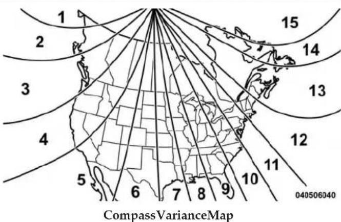
• PerformCompassCalibration
Push the Compass button on the faceplate, then press the "Calibration" button on the touchscreen to change this setting. This compass is self-calibrating, which eliminates the need to manually reset the compass. When the vehicle is new, the compass may appear erratic and the
Driver Information Display (DID) will display CAL until the compass is calibrated. You may also calibrate the compass by pressing the "ON" button on the touchscreen and completing one or more 360-degree turns (in an area free from large metal or metallic objects) until the CAL indicator displayed in the DID turns off. The compass will now function normally.
Audio
After pressing the "Audio" button on the touchscreen the following settings will be available:
•Balance/Fade
This feature allows you to adjust the Balance and Fade settings. Press and drag the speaker icon or use the arrows to adjust, tap the "C" icon to readjust to the center. Press the back arrow button on the touchscreen to return to the previous menu.
• Equalizer
When in this display you may adjust the Bass, Mid and Treble settings. Adjust the settings with the "+" and "-" buttons on the touchscreen or by selecting any point on the scale between the "+" and "-" buttons on the touchscreen. Press the back arrow button on the touchscreen to return to the previous menu.
- SpeedAdjustedVolume
This feature increases or decreases volume relative to vehicle speed. To change the Speed Adjusted Volume press the "Speed Adjusted Volume" button on the touchscreen and select from "Off," "1," "2" or "3" buttons on the touchscreen. Press the back arrow button on the touchscreen to return to the previous menu.
- SurroundSound—IfEquipped
This feature provides simulated surround sound mode. To make your selection, press the "Surround Sound"
276 UNDERSTANDING YOUR INSTRUMENT PANEL
button on the touchscreen, select "On" or "Off." Press the back arrow button on the touchscreen to return to the previous menu.
• AUXVolumeOffset—IfEquipped
This feature provides the ability to tune the audio level for portable devices connected through the AUX input. To make your selection, press the "AUX Volume Offset" button on the touchscreen, select "On" or "Off." Press the back arrow button on the touchscreen to return to the previous menu.
- Loudness—IfEquipped
This feature improves sound quality at lower volumes. To make your selection, press the “Loudness” button on the touchscreen, select “On” or “Off.” Press the back arrow button on the touchscreen to return to the previous menu.
Phone/Bluetooth®
After pressing the "Phone/Bluetooth®" button on the touchscreen the following settings will be available:
•PairedPhones
This feature shows which phones are paired to the Phone/Bluetooth® system. For further information, refer to the Uconnect® Supplement Manual.
•PairedAudioSources
This feature shows which audio devices are paired to the Phone/Bluetooth® system. For further information, refer to the Uconnect® Supplement Manual.
TrailerBrake
After pressing the "Trailer Brake" button on the touchscreen the following settings will be available:
- TrailerSelect
When this feature is selected, the Trailer Type can be selected between "Trailer 1," "Trailer 2," "Trailer 3" and "Trailer 4." To make your selection, scroll up or down until the preferred setting is highlighted, then press and release the SELECT button until a check-mark appears next to the setting, showing that the setting has been selected.
- TrailerBrakeType
When this feature is selected, the Trailer Brake Type can be changed between "Light Electric," "Heavy Electric," "Light EOH" and "Heavy EOH." To make your selection, scroll up or down until the preferred setting is highlighted, then press and release the SELECT button until a check-mark appears next to the setting, showing that the setting has been selected. Refer to "Integrated Trailer Brake Module" in "Starting And Operating."
SiriusXMSetup—IfEquipped
After pressing the "SiriusXM Setup" button on the touchscreen, the following settings will be available:
- ChannelSkip
SiriusXM can be programmed to designate a group of channels that are the most desirable to listen to or to exclude undesirable channels while scanning. To make your selection, press the "Channel Skip" button on the touchscreen, select the channels you would like to skip followed by pressing the back arrow button on the touchscreen.
- SubscriptionInformation
New vehicle purchasers or lessees will receive a free limited time subscription to SiriusXM Satellite Radio
278 UNDERSTANDING YOUR INSTRUMENT PANEL
with your radio. Following the expiration of the free services, it will be necessary to access the information on the Subscription Information screen to re-subscribe.
Press the "Subscription Info" button on the touchscreen to access the Subscription Information screen.
Write down the SIRIUS ID numbers for your receiver. To reactivate your service, either call the number listed on the screen or visit the provider online.
NOTE:SiriusXM Travel Link is a separate subscription and is available for U.S. residents only.
Uconnect® RADIOS — IF EQUIPPED
For detailed information about your Uconnect® radio, refer to your Uconnect® Supplement Manual.
iPod®/USB/MP3 CONTROL — IF EQUIPPED
Located inside the center console upper lid, this feature allows an iPod® or external USB device to be plugged into the USB port.
iPod® control supports Mini, 4G, Photo, Nano, 5G iPod® and iPhone® devices. Some iPod® software versions may not fully support the iPod® control features. Please visit Apple's website for software updates.
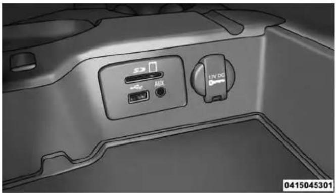
natural_image
Interior view of a car air conditioner unit with control panel and indicator lights (no text or symbols visible)CenterConsoleUSB/AUXSDCardMediaHub
For further information, refer to the Uconnect® Supplement Manual or visit UconnectPhone.com.
UNDERSTANDING YOUR INSTRUMENT PANEL 279
STEERING WHEEL AUDIO CONTROLS — IF EQUIPPED
The remote sound system controls are located on the back surface of the steering wheel. Reach behind the wheel to access the switches.

natural_image
Interior view of a car steering wheel with black arrows indicating clockwise direction (no text or symbols)045035190
RemoteSoundSystemControls(RearviewOfSteering Wheel)
280 UNDERSTANDING YOUR INSTRUMENT PANEL
The right hand control is a rocker type switch with a push-button in the center. Pushing the top of the switch will increase the volume, and pushing the bottom of the switch will decrease the volume.
The button located in the center of the right hand control will switch modes to Radio, CD or other valid audio sources.
The left hand control is a rocker type switch with a push-button in the center. The function of the left hand control is different depending on which mode you are in.
The following describes the left hand control operation in each mode.
Radio Operation
Pushing the top of the switch will SEEK up for the next listenable station and pushing the bottom of the switch will SEEK down for the next listenable station.
The button located in the center of the left hand control will tune to the next pre-set station that you have programmed in the radio pre-set buttons.
CD Player — If Equipped
Pushing the top of the switch once will go to the next track on the CD. Pressing the bottom of the switch once will go to the beginning of the current track or to the beginning of the previous track if it is within eight seconds after the current track begins to play.
If you push the switch up or down twice it plays the second track, three times, it will play the third, etc.
CD/DVD DISC MAINTENANCE
To keep a CD/DVD in good condition, take the following precautions:
-
Handle the disc by its edge; avoid touching the surface.
-
If the disc is stained, clean the surface with a soft cloth, wiping from center to edge.
- Do not apply paper or tape to the disc; avoid scratching the disc.
- Do not use solvents such as benzene, thinner, cleaners, or anti-static sprays.
- Store the disc in its case after playing.
- Do not expose the disc to direct sunlight.
- Do not store the disc where temperatures may become too high.
NOTE: If you experience difficulty in playing a particular disc, it may be damaged (e.g., scratched, reflective coating removed, a hair, moisture or dew on the disc) oversized, or have protection encoding. Try a known good disc before considering disc player service.
Under certain conditions, the mobile phone being on in your vehicle can cause erratic or noisy performance from your radio. This condition may be lessened or eliminated by relocating the mobile phone antenna. This condition is not harmful to the radio. If your radio performance does not satisfactorily “clear” by the repositioning of the antenna, it is recommended that the radio volume be turned down or off during mobile phone operation when not using Uconnect® (if equipped).
Regulatory And Safety Information
USA/CANADA
Exposure to Radio Frequency Radiation
The radiated output power of the internal wireless radio is far below the FCC radio frequency exposure limits.
282 UNDERSTANDING YOUR INSTRUMENT PANEL
Nevertheless, the wireless radio shall be used in such a manner that the radio is 20 cm or further from the human body.
The internal wireless radio operates within guidelines found in radio frequency safety standards and recommendations, which reflect the consensus of the scientific community.
The radio manufacturer believes the internal wireless radio is safe for use by consumers. The level of energy emitted is far less than the electromagnetic energy emitted by wireless devices such as mobile phones. However, the use of wireless radios may be restricted in some situations or environments, such as aboard airplanes. If you are unsure of restrictions, you are encouraged to ask for authorization before turning on the wireless radio.
This device complies with Part 15 of the FCC Rules and with Industry Canada license-exempt RSS standard(s). Operation is subject to the following two conditions:
-
This device may not cause harmful interference.
-
This device must accept any interference received, including interference that may cause undesired operation.
- This equipment has been tested and found to comply with the limits for a Class B digital device, pursuant to Part 15 of the FCC Rules. These limits are designed to provide reasonable protection against harmful interference in a residential installation. This equipment generates, uses and can radiate radio frequency energy and, if not installed and used in accordance with the instructions, may cause harmful interference to radio communications. However, there is no guarantee that interference will not occur in a particular installation.
-
If this equipment does cause harmful interference to radio or television reception, which can be determined by turning the equipment off and on, the user is encouraged to try to correct the interference by one or more of the following measures:
-
Increase the separation between the equipment and receiver.
- Consult the dealer or an experienced radio technician for help.
CLIMATE CONTROLS
The Climate Control System allows you to regulate the temperature, amount, and direction of air circulating throughout the vehicle. The controls are located on the instrument panel below the radio.
Manual Climate Controls Without Touchscreen — If Equipped
The controls for the manual heating and air conditioning system in this vehicle consist of a series of outer rotary dials and inner push knobs. These comfort controls can be set to obtain desired interior conditions.
284 UNDERSTANDING YOUR INSTRUMENT PANEL
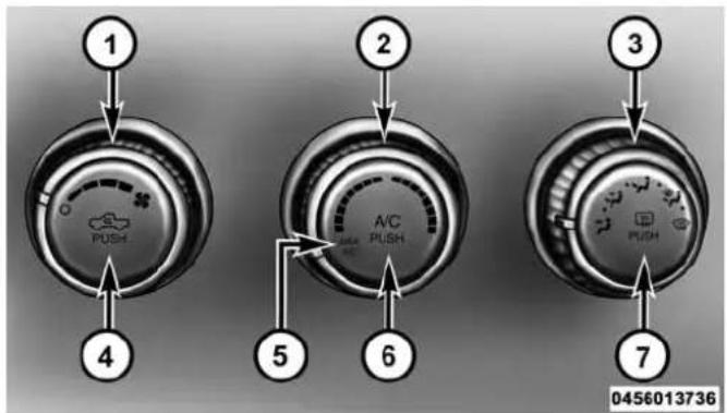
ManualClimateControls
1 — Front Blower 5 — MAX A/C
2 — Temperature Control 6 — Air Conditioning (A/C)
3 — MODE Control 7 — DEFROST Mode
4 — RECIRCULATION Control
FrontBlowerControl

045671419
There are four blower speeds. Use this control to regulate the amount of air forced through the system in any mode you select. The blower speed increases as you move the control clockwise from the OFF position.
TemperatureControl
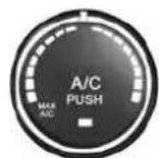
045671420
Use this control to regulate the temperature of the air inside the passenger compartment. Rotating the knob counterclockwise, from top center into the blue area of the scale, indicates cooler temperatures. Rotating the knob clockwise, into the red area, indicates
warmer temperatures.
AirConditioningOperation

Push the A/C button to engage the Air Conditioning (A/C). A LED will illuminate when the A/C system is engaged.
MAXA/C
For maximum cooling, when MAX A/C is selected the A/C is turned on automatically and the air is recirculated.
UNDERSTANDING YOUR INSTRUMENT PANEL 285
NOTE:A/C cannot be deselected when in MAX A/C position. The LED will blink three times if the A/C button is pushed. If your air conditioning performance seems lower than expected, check the front of the A/C condenser (located in front of the radiator), for an accumulation of dirt or insects. Clean with a gentle water spray from behind the radiator and through the condenser. Fabric front fascia protectors may reduce airflow to the condenser, reducing air conditioning performance.
ModeControl(AirDirection)

045671421
Mode control allows you to choose from several patterns of air distribution. You can select either a primary mode, as identified by the symbols, or a blend of two of these modes. The closer the control is to a particular mode, the more air distribution you
receive from that mode.
286 UNDERSTANDING YOUR INSTRUMENT PANEL
PanelMode

Air is directed through the outlets in the instrument panel. These outlets can be adjusted to direct 7.
Bi-LevelMode

Air is directed through the panel and floor outlets.
NOTE: There is a difference in temperature (in any conditions other than full cold or full hot), between the upper and lower outlets for added comfort. The warmer air goes to the floor outlets. This feature gives improved comfort during sunny but cool conditions.
FloorMode

Air is directed through the floor outlets with a small amount through the defrost and side win-emist outlets.
MixMode

Air is directed through the floor, defrost and side window demist outlets. This setting works best in or snowy conditions that require extra heat at the shield. This setting is good for maintaining comfort, reducing moisture on the windshield.
DefrostMode

Air is directed through the windshield and side window demist outlets. Use the DEFROST mode maximum blower and warm temperature settings at windshield and side window defrosting.
NOTE: The air conditioning compressor operates in MIX and DEFROST, or a blend of these modes even if the A/C button is not pushed. This dehumidifies the air to help dry the windshield. To improve fuel economy, use these modes only when necessary.
RecirculationControl

Push the Recirculation Control button to choose between outside air intake or recirculation of the air inside the vehicle. A LED will illuminate when you are in Recirculation mode. Only use the Recirculation mode to temporarily block out any outside odors, smoke, or dust, and to cool the interior rapidly upon initial start-up in very hot or humid weather.
NOTE:
- If the RECIRCULATION button is pushed when the system is in Defrost mode, the Recirculation LED indicator will flash three times and then turn off to indicate Recirculation mode is not allowed.
- Continuous use of the Recirculation mode may make the inside air stuffy and window fogging may occur. Extended use of this mode is not recommended.
- In cold or damp weather, the use of the Recirculation mode will cause windows to fog on the inside because of moisture buildup inside the vehicle. For maximum defogging, select the outside air position.
- The A/C can be deselected manually without disturbing the mode control selection by pushing the A/C button.
288 UNDERSTANDING YOUR INSTRUMENT PANEL
AirOutlets
The airflow from each of the instrument panel outlets can be adjusted for direction, and turned on or off to control airflow.
NOTE: For maximum airflow to the rear, the center instrument panel outlets can be directed toward the rear seat passengers.
EconomyMode
If ECONOMY mode is desired, push the A/C button to turn off the LED indicator and the A/C compressor. Rotate the temperature control knob to the desired temperature. Also, make sure to select only Panel, Bi-Level or Floor modes.
Stop/StartSystem—IfEquipped
While in an Autostop, the Climate Controls system may automatically adjust airflow to maintain cabin comfort. Customer settings will be maintained upon return to an engine running condition.
Manual Climate Controls With Touchscreen — If Equipped
ButtonsOnTheFaceplate
The buttons on the faceplate are located below the radio touchscreen.

ClimateControls—ButtonsOnTheFaceplate
UNDERSTANDING YOUR INSTRUMENT PANEL 289
ButtonsOnTheTouchscreen
Buttons on the touchscreen are accessible on the radio.

TemperatureControls—ButtonsOnTheTouchscreen
ButtonDescriptions(AppliesToBothButtonsOnTheFaceplateandButtonsOnTheTouchscreen)
1.MAXA/CButton
Press and release to toggle between MAX A/C and the prior settings. The button on the touchscreen illuminates when MAX A/C is ON. In MAX A/C, the blower level and mode position can be adjusted to desired user settings. Pressing other settings will cause the MAX A/C operation to switch to the prior settings and the MAX A/C indicator will turn off.
2.A/CButton
Press and release to change the current setting, the indicator illuminates when A/C is ON. Performing this function again will cause the A/C operation to switch into manual mode and the A/C indicator will turn off.
290 UNDERSTANDING YOUR INSTRUMENT PANEL
3. RecirculationButton
Press and release to change the current setting; the indicator illuminates when ON.
4.FrontDefrostButton
Press and release to change the current airflow setting to Defrost mode. The indicator illuminates when this feature is ON. Air comes from the windshield and side window demist outlets. When the defrost button is selected, the blower level will increase. Use Defrost mode with maximum temperature settings for best windshield and side window defrosting and defogging. Performing this function will cause the ATC to switch into manual mode. If the front defrost mode is turned off the climate system will return the previous setting.
5.DefrostButton
Press and release this button to turn on the rear window defroster (if equipped) and the heated outside mirrors (if equipped). An indicator will illuminate when the rear window defroster is on. The rear window defroster automatically turns off after 10 minutes.
CAUTION!
Failure to follow these cautions can cause damage to the heating elements:
- Usecarewhenwashingtheinsideoftherear window.Donotuseabrasivewindowcleanerson theinteriorsurfaceofthewindow.Useasoftcloth andamildwashingsolution,wipingparalleltothe heatingelements.Labelscanbepeeledoffafter soakingwithwarmwater.
- Donotusescrapers, sharpinstruments, or abrasive window cleanerson the interiorsurface of the window.
- Keepallobjectsasafedistancefromthewindow.
6.Modes
The airflow distribution mode can be adjusted so air comes from the instrument panel outlets, floor outlets, and demist outlets. The Mode settings are as follows:
- PanelMode

Air comes from the outlets in the instrument panel. Each of these outlets can be individually adjusted to direct the flow of air. The air vanes of the center outlets and outboard outlets can be moved up and down or side to side to regulate airflow direction. There is a shut off wheel located below the air vanes to shut off or adjust the amount of airflow from these outlets.
- Bi-LevelMode

Air comes from the instrument panel outlets and floor outlets. A slight amount of air is directed through the defrost and side window demister outlets.
NOTE:BI-LEVEL mode is designed under comfort conditions to provide cooler air out of the panel outlets and warmer air from the floor outlets.
- FloorMode

Air comes from the floor outlets. A slight amount of air is directed through the defrost and side window demister outlets.
- MixMode

Air comes from the floor, defrost and side window demister outlets. This mode works best in cold or snowy conditions.
NOTE: The air conditioning compressor operates in MIX and DEFROST modes even if the A/C button is not pressed. This dehumidifies the air to help dry the windshield. To improve fuel economy, utilize these modes only when required.
292 UNDERSTANDING YOUR INSTRUMENT PANEL
7.BlowerControl
Blower control is used to regulate the amount of air forced through the climate system. There are seven blower speeds available. Adjusting the blower will cause automatic mode to switch to manual operation. The speeds can be selected using either buttons on the faceplate or buttons on the touchscreen as follows:
BlowerControlKnobOnTheFaceplate
The blower speed increases as you turn the control clockwise from the lowest blower setting. The blower speed decreases as you turn the blower control knob counterclockwise.
ButtonsOnTheTouchscreen
Use the small blower icon to reduce the blower setting and the large blower icon to increase the blower setting. Blower can also be selected by pressing the blower bar area between the icons.
8.ClimateControlOFFButton
Press and release this button to turn the Climate Control ON/OFF.
9. TemperatureControlButtonDown
Push the button on the faceplate for cooler temperature settings. On the touchscreen, slide the temperature bar towards the blue arrow button for cooler temperature settings.
10. TemperatureControlUpButton
Push the button on the faceplate for warmer temperature settings. On the touchscreen, slide the temperature bar towards the blue arrow button for cooler temperature settings.
RecirculationControl
When outside air contains smoke, odors, or high humidity, or if rapid cooling is desired, you may wish to recirculate interior air by pressing the RECIRCULATION control but Recirculation mode should only be used temporarily. The recirculation LED will illuminate on the blower control knob when this button is selected. Push the button a second time to turn off the Recirculation mode LED and allow outside air into the vehicle.
NOTE: In cold weather, use of Recirculation mode may lead to excessive window fogging. The Recirculation mode is not allowed in Defrost mode to improve window clearing operation. Recirculation will be disabled automatically if these modes are selected.
Automatic Climate Controls With Touchscreen — If Equipped
ButtonsOnTheFaceplate
The buttons on the faceplate are located below the Uconnect® screen.

AutomaticClimateControls—ButtonsOnThe Faceplate
294 UNDERSTANDING YOUR INSTRUMENT PANEL
ButtonsOnTheTouchscreen
Buttons on the touchscreen are accessible on the Uconnect® system screen.
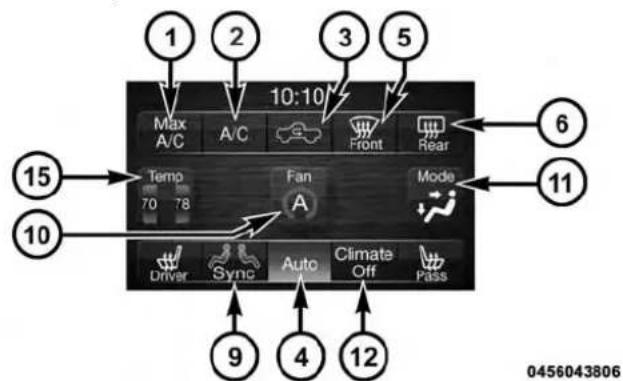
Uconnect®5.0AutomaticTemperatureControls—ButtonsOnTheTouchscreen

Uconnect®8.4AutomaticTemperatureControls—ButtonsOnTheTouchscreen
ButtonDescriptions(AppliesToBothButtonsOn TheFaceplateAndButtonsOnTheTouchscreen)
1.MAXA/CButton
Press and release to change the current setting, the indicator illuminates when MAX A/C is ON. Performing
this function again will cause the MAX A/C operation to switch into manual mode and the MAX A/C indicator will turn off.
2.A/CButton
Press and release to change the current setting, the indicator illuminates when A/C is ON. Performing this function again will cause the A/C operation to switch into manual mode and the A/C indicator will turn off.
3. RecirculationButton
Press and release to change the current setting, the indicator illuminates when ON.
4. AUTOOperationButton
Automatically controls the interior cabin temperature by adjusting airflow distribution and amount. Performing this function will cause the ATC to switch between manual mode and automatic modes. Refer to “Automatic Operation” for more information.
5.FrontDefrostButton
Press and release to change the current airflow setting to Defrost mode. The indicator illuminates when this feature is ON. Air comes from the windshield and side window demist outlets. When the defrost button is selected, the blower level will increase. Use Defrost mode with maximum temperature settings for best windshield and side window defrosting and defogging. Performing this function will cause the ATC to switch into manual mode. If the front defrost mode is turned off the climate system will return the previous setting.
6.DefrostButton
Press and release this button to turn on the rear window defroster (if equipped) and the heated outside mirrors (if equipped). An indicator will illuminate when the rear window defroster is on. The rear window defroster automatically turns off after 10 minutes.
CAUTION!
Failure to follow these cautions can cause damage to the heating elements:
- Usecarewhenwashingtheinsideoftherear window.Donotuseabrasivewindowcleanerson theinteriorsurfaceofthewindow.Useasoftcloth andamildwashingsolution,wipingparalleltothe heatingelements.Labelscanbepeeledoffafter soakingwithwarmwater.
- Donotusescrapers, sharpinstruments, or abrasive window cleanerson the interiorsurface of the window.
- Keepallobjectsasafedistancefromthewindow.
7.PassengerTemperatureControlUpButton (Uconnect®8.4)
Provides the passenger with independent temperature control. Push the button on the faceplate for warmer temperature settings or on the touchscreen, press and slide the temperature bar towards the red arrow for warmer temperature settings.
NOTE: Pressing this button while in Sync mode will automatically exit Sync.
8.PassengerTemperatureControlDownButton (Uconnect®8.4)
Provides the passenger with independent temperature control. Push the button on the faceplate for cooler temperature settings or on the touchscreen, press and slide the temperature bar towards the blue arrow for cooler temperature settings.
NOTE: Pressing this button while in Sync mode will automatically exit Sync.
9.SYNC
Press the Sync button on the touchscreen to toggle the Sync feature On/Off. The Sync indicator is illuminated when this feature is enabled. Sync is used to synchronize the passenger temperature setting with the driver temperature setting. Changing the passenger temperature setting while in Sync will automatically exit this feature.
10.BlowerControl
Blower control is used to regulate the amount of air forced through the climate system. There are seven blower speeds available. Adjusting the blower will cause automatic mode to switch to manual operation. The speeds can be selected using either Buttons on the faceplate or buttons on the touchscreen as follows:
BlowerControlKnobOnTheFaceplate
The blower speed increases as you turn the control clockwise from the lowest blower setting. The blower speed decreases as you turn the blower control knob counterclockwise.
ButtonOnTheTouchscreen
Use the small blower icon to reduce the blower setting and the large blower icon to increase the blower setting. Blower can also be selected by pressing the blower bar area between the icons.
11.Modes
The airflow distribution mode can be adjusted so air comes from the instrument panel outlets, floor outlets, demist outlets and defrost outlets. The Mode settings are as follows:
- PanelMode

Air comes from the outlets in the instrument panel. Each of these outlets can be individually adjusted to direct the flow of air. The air vanes of the center outlets and outboard outlets can be moved up and down or side to side to regulate airflow direction. There is a shut off wheel located below the air vanes to shut off or adjust the amount of airflow from these outlets.
- Bi-LevelMode

Air comes from the instrument panel outlets and floor outlets. A slight amount of air is directed through the defrost and side window demister outlets.
NOTE:BI-LEVEL mode is designed under comfort conditions to provide cooler air out of the panel outlets and warmer air from the floor outlets.
- FloorMode

Air comes from the floor outlets. A slight amount of air is directed through the defrost de window demister outlets.
- MixMode

Air comes from the floor, defrost and side window demist outlets. This mode works best in cold or snowy conditions.
12. ClimateControlOFFButton
Press and release this button to turn the Climate Control ON/OFF.
UNDERSTANDING YOUR INSTRUMENT PANEL 299
13.DriverTemperatureControlDownButton (Uconnect®8.4)
Provides the driver with independent temperature control. Push the button on the faceplate for cooler temperature settings or on the touchscreen, press and slide the temperature bar towards the blue arrow for cooler temperature settings.
NOTE: In Sync mode, this button will also automatically adjust the passenger temperature setting at the same time.
14. DriverTemperatureControlUpButton(Uconnect®8.4)
Provides the driver with independent temperature control. Push the button on the faceplate button for warmer temperature settings or on the touchscreen, press and slide the temperature bar towards the red arrow for warmer temperature settings.
NOTE: In Sync mode, this button will also automatically adjust the passenger temperature setting at the same time.
15.TemperatureControl(Uconnect®5.0)
Press the temperature button on the touchscreen to regulate the temperature of the air inside the passenger compartment. Moving the temperature bar into the red area, indicates warmer temperatures. Moving the temperature bar into the blue area indicates cooler temperatures.
Climate Control Functions
A/C(AirConditioning)
The Air Conditioning (A/C) button allows the operator to manually activate or deactivate the air conditioning system. When the air conditioning system is turned on, cool dehumidified air will flow through the outlets into the cabin. For improved fuel economy, press the A/C
300 UNDERSTANDING YOUR INSTRUMENT PANEL
button to turn off the air conditioning and manually adjust the blower and airflow mode settings. Also, make sure to select only Panel, Bi-Level or Floor modes.
NOTE:
- For Manual Climate Controls, if the system is in Mix, Floor or Defrost Mode, the A/C can be turned off, but the A/C system shall remain active to prevent fogging of the windows.
- If fog or mist appears on the windshield or side glass, select Defrost mode and adjust blower speed if needed.
- If your air conditioning performance seems lower than expected, check the front of the A/C condenser (located in front of the radiator), for an accumulation of dirt or insects. Clean with a gentle water spray from behind the radiator and through the condenser. Fabric front fascia protectors may reduce airflow to the condenser, reducing air conditioning performance.
MAXA/C
MAX A/C sets the control for maximum cooling performance.
Press and release to toggle between MAX A/C and the prior settings. The button on the touchscreen illuminates when MAX A/C is ON.
In MAX A/C, the blower level and mode position can be adjusted to desired user settings. Pressing other settings will cause the MAX A/C operation to switch to the prior settings and the MAX A/C indicator will turn off.
RecirculationControl

When outside air contains smoke, odors, or high humidity, or if rapid cooling is desired, you may wish to recirculate interior air by pressing the RECIRCULATION control button on chscreen or faceplate. Recirculation mode
should only be used temporarily. The recirculation LED button on the faceplate will illuminate when either button is selected. Push either button a second time to turn off the Recirculation mode LED and allow outside air into the vehicle.
NOTE: In cold weather, use of Recirculation mode may lead to excessive window fogging. The recirculation feature may be unavailable (button on the touchscreen greyed out) if conditions exist that could create fogging on the inside of the windshield. On systems with Manual Climate Controls, the recirculation mode is not allowed in Defrost mode to improve window clearing operation. Recirculation will be disabled automatically if this mode is selected. Attempting to use Recirculation while in this mode will cause the LED in the control button on the faceplate to blink and then turn off.
Automatic Temperature Control (ATC)
AutomaticOperation
- Push the AUTO button on the faceplate or press the "AUTO" button on the touchscreen.
- Next, adjust the temperature you would like the system to maintain by adjusting the driver and passenger temperature buttons on the faceplate or buttons on the touchscreen. Once the desired temperature is displayed, the system will achieve and automatically maintain that comfort level.
- When the system is set up for your comfort level, it is not necessary to change the temperature. You will experience the greatest efficiency by simply allowing the system to function automatically.
302 UNDERSTANDING YOUR INSTRUMENT PANEL
NOTE:
- It is not necessary to move the temperature settings. The system automatically adjusts the temperature, mode, and blower speed to provide comfort as quickly as possible.
- The temperature can be displayed in U.S. or Metric units by selecting the Uconnect® customer-programmable feature. Refer to the “Uconnect® System Settings” in this section of the manual.
To provide you with maximum comfort in the Automatic mode, during cold start-ups the blower fan will remain on low until the engine warms up. The blower will increase in speed and transition into Auto mode.
ManualOperationOverride
The system allows for manual selection of blower speed, air distribution mode, A/C status and recirculation control.
The blower fan speed can be set to any fixed speed by adjusting the blower control. The fan will now operate at a fixed speed until additional speeds are selected. This allows the front occupants to control the volume of air circulated in the vehicle and cancel the Auto mode.
The operator can also select the direction of the airflow by selecting one of the available mode settings. A/C operation and Recirculation control can also be manually selected in Manual operation.
NOTE: Each of these features operates independently from each other. If any feature is controlled manually, temperature control will continue to operate automatically.
Operating Tips
NOTE: Refer to the chart at the end of this section for suggested control settings for various weather conditions.
SummerOperation
The engine cooling system must be protected with a high-quality antifreeze coolant to provide proper corrosion protection and to protect against engine overheating. OAT coolant (conforming to MS.90032) is recommended. Refer to “Maintenance Procedures” in “Maintaining Your Vehicle” for proper coolant selection.
WinterOperation
To ensure the best possible heater and defroster performance, make sure the engine cooling system is functioning properly and the proper amount, type, and concentration of coolant is used. Refer to "Maintenance Procedures" in "Maintaining Your Vehicle" for proper coolant selection. Use of the air Recirculation mode during Winter months is not recommended because it may cause window fogging.
Vacation/Storage
Any time you store your vehicle or keep it out of service (i.e., vacation) for two weeks or more, run the air conditioning system at idle for about five minutes in fresh air with the blower setting in high. This will ensure adequate system lubrication to minimize the possibility of compressor damage when the system is started again.
304 UNDERSTANDING YOUR INSTRUMENT PANEL
WindowFoggingandFrosting
Vehicle windows tend to fog on the inside of the glass in mild, rainy and/or humid weather. Windows may frost on the inside of the glass in very cold weather. To clear the windows, select Defrost or Mix mode and increase the front blower speed. Do not use the Recirculation mode without A/C for long periods, as fogging may occur.
NOTE: Automatic Temperature Controls (ATC) will automatically adjust the climate control settings to reduce or eliminate window fogging on the front windshield. When this occurs, recirculation will be unavailable.
OutsideAirIntake
Make sure the air intake, located directly in front of the windshield, is free of obstructions such as leaves. Leaves collected in the air intake may reduce airflow, can cause odor, and if they enter the plenum they could plug the water drains. In winter months, ensure the air intake is clear of ice, slush and snow.
ControlSettingSuggestionsForVariousWeatherConditions
| WEATHER | CONTROL SETTINGS |
Hot weather and vehicle interior is very hot  | Set the mode control toA/C on, and blower on high. Roll down the windows for a minute to flush out the hot air. Once comfort is achieved adjust controls for comfort. |
Warm weather  | Turn A/C on and set the mode control to theposition. |
Co  | Operate in posit |
| Set the mode control to and turn on A/C to keep windows clear. | |
| Set the mode control to the fogging starts to occur, move the control towards the position. |
0456001003
OperatingTipsChart
306 UNDERSTANDING YOUR INSTRUMENT PANEL
Uconnect® VOICE RECOGNITION
Introducing Uconnect®
Start using Uconnect® Voice Recognition with these helpful quick tips. It provides the key Voice Commands and tips you need to know to control your Uconnect® 5.0 or 8.4A/8.4AN system.
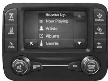
0501043050
Uconnect®5.0
Key Features:
- 5" touchscreen
• Three buttons on either side of the display

Uconnect®8.4AN
If you see the HD icon on your touchscreen, you have the Uconnect® 8.4AN system. If not, you have a Uconnect® 8.4A system.
Get Started
- Visit UconnectPhone.com to check mobile device and feature compatibility and to find phone pairing instructions.
- Reduce background noise. Wind and passenger conversations are examples of noise that may impact recognition.
- Speak clearly at a normal pace and volume while facing straight ahead. The microphone is positioned on the rearview mirror and aimed at the driver.
UNDERSTANDING YOUR INSTRUMENT PANEL
307
- Each time you give a Voice Command, you must first push either the VR or Phone button, wait until after the beep, then say your Voice Command.
- You can interrupt the help message or system prompts by pushing the VR or Phone button and saying a Voice Command from current category.
Two buttons are all you need to control your Uconnect® system with your voice.
308 UNDERSTANDING YOUR INSTRUMENT PANEL
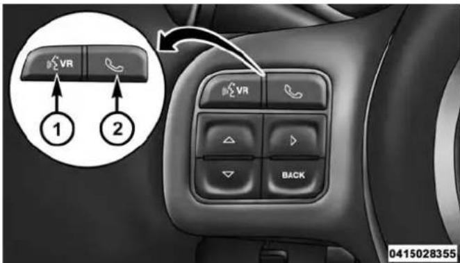
VoiceRecognition(VR)/PhoneButtons
1 — Push To Begin Radio, Media, Navigation, Apps And Climate Functions
2 — Push To Initiate Or To Answer A Phone Call, Send Or Receive A Text
Basic Voice Commands
The basic Voice Commands below can be given at any point while using your Uconnect® system.
Push the VR button 📋VR. After the beep, say...
- Cancelto stop a current voice session
- Helpto hear a list of suggested Voice Commands
- Repeat to listen to the system prompts again
Notice the visual cues that inform you of your voice recognition system's status. Cues appear on the touchscreen.

Uconnect®5.0Uconnect®8.4A/8.4AN
UNDERSTANDING YOUR INSTRUMENT PANEL 309
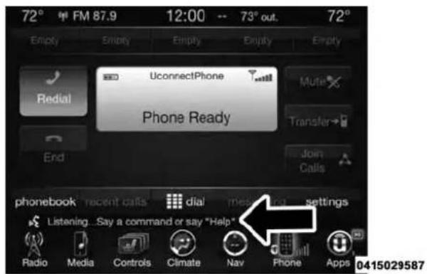
310 UNDERSTANDING YOUR INSTRUMENT PANEL
Radio
Use your voice to quickly get to the AM, FM or SiriusXM Satellite Radio® stations you would like to hear. (Subscription or included SiriusXM Satellite Radio® trial required.)
Push the VR button (VR). After the beep, say...
• Tunetoninety-five-point-five FM
• TunetoSatellite Channel Hits 1
TIP: At any time, if you are not sure of what to say or want to learn a Voice Command, press the VR button (VR) and say "Help." The system will provide you with a list of commands.

Uconnect®5.0Radio
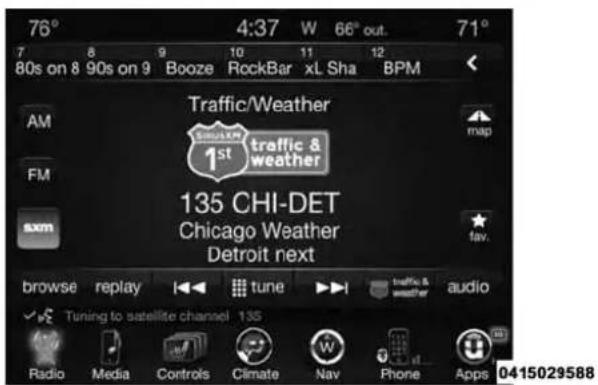
Uconnect®8.4A/8.4ANRadio
UNDERSTANDING YOUR INSTRUMENT PANEL 311
Media
Uconnect® offers connections via USB, SD, Bluetooth® and auxiliary ports (If Equipped). Voice operation is only available for connected USB and iPod® devices. (Remote CD player optional and not available on all vehicles.)
Push the VR button (VR). After the beep, say one of the following commands and follow the prompts to switch your media source or choose an artist.
•Changesourceto Bluetooth®
- Changesourceto iPod®
•Changesourceto USB
- Play artist Beethoven; Play album Greatest Hits; Play song Moonlight Sonata; PlaygenreClassical
312 UNDERSTANDING YOUR INSTRUMENT PANEL
TIP: Press the Browse button on the touchscreen to see all of the music on your iPod® or USB device. Your Voice Command must match exactly how the artist, album, song and genre information is displayed.
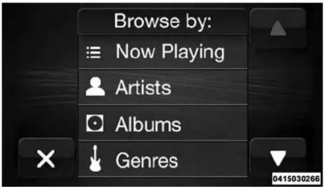
Uconnect®5.0Media
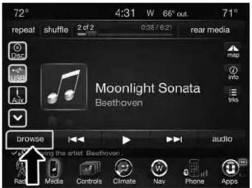
Uconnect®8.4A/8.4ANMedia
UNDERSTANDING YOUR INSTRUMENT PANEL 313
Climate (8.4A/8.4AN)
Too hot? Too cold? Adjust vehicle temperatures hands-free and keep everyone comfortable while you keep moving ahead. (If vehicle is equipped with climate control.)
Push the VR button (CVR). After the beep, say one of the following commands:
- Setdrivertemperatureto70 degrees
- Setpassengertemperatureto70 degrees
TIP: Voice Command for Climate may only be used to adjust the interior temperature of your vehicle. Voice Command will not work to adjust the heated seats or steering wheel if equipped.

Uconnect8.4A/8.4ANClimate
314 UNDERSTANDING YOUR INSTRUMENT PANEL
Navigation (8.4A/8.4AN)
The Uconnect® navigation feature helps you save time and become more productive when you know exactly how to get to where you want to go. (Navigation is optional on the Uconnect® 8.4A system. See your dealer to activate navigation at any time.)
- To enter a destination, push the VR button (VR). After the beep, say:
- For the 8.4A Uconnect® System, say: "Enterstate."
- For the 8.4AN Uconnect® System, say: "Navigate to 800 Chrysler Drive Auburn Hills, Michigan."
- Then follow the system prompts.
TIP: To start a POI search, push the VR button After the beep, say: " Findnearestcoffee shop."
Uconnect®8.4A/8.4ANNavigation
UNDERSTANDING YOUR INSTRUMENT PANEL 315
Phone
Making and answering hands-free phone calls is easy with Uconnect®. When the Phonebook button is illuminated on your touchscreen, your system is ready. Check UconnectPhone.com for mobile phone compatibility and pairing instructions.
Push the Phone button 📋. After the beep, say one of the following commands...
- CallJohn Smith
•Dial123-456-7890 and follow the system prompts
• Redial(call previous outgoing phone number) - Callback(call previous incoming phone number)
TIP: When providing a Voice Command, push the Phone button 🔍 and say "Call," then pronounce the name exactly as it appears in your phone book. When a contact has multiple phone numbers, you can say "CallJohn Smith work."

Uconnect®5.0Phone
316 UNDERSTANDING YOUR INSTRUMENT PANEL

Uconnect®8.4A/8.4ANPhone
Voice Text Reply
Uconnect® will announce incomingtext messages. Push the Phone button and say Listen.(Must have compatible mobile phone paired to Uconnect® system.)
- Once an incoming text message is read to you, push the Phone button 🔔. After the beep, say: "Reply."
- Listen to the Uconnect® prompts. After the beep, repeat one of the pre-defined messages and follow the system prompts.
| PRE-DEFINEDVOICETEXTREPLYRESPONSES | ||
| Yes. Stuck in Traffic. See you later. | ||
| No. | Start without me. | I'll be Late. |
| Okay. Where are you? I will beminutes late. | ||
| Call me. | Are you there yet? | |
| I'll call you later. | I need directions. | See you inof minutes. |
| I'm on my way. | Can't talk right | |
| I'm lost. Thanks. now. | ||
UNDERSTANDING YOUR INSTRUMENT PANEL 317
TIP:Your mobile phone must have the full implementation of the Message Access Profile (MAP) to take advantage of this feature. For details about MAP, visit UconnectPhone.com.AppleiPhone®iOS6orlatersupportsreadingincomingtextmessagesonly.
Uconnect® Access\* (8.4A/8.4AN)
An included trial and/or subscription is required to take advantage of the Uconnect® Access services in the next section of this guide. To register with Uconnect® Access, press the Apps button on the 8.4-inch touchscreen to get started. Detailed registration instructions can be found on the next page.
*Uconnect® Access is available only on equipped vehicles purchased within the continental United States and Alaska. Services can only be used where coverage is available; see coverage map for details.
CALL 9-1-1 Call
⚠️ Theft Alarm Notification
Remote Door Lock/Unlock
Stolen Vehicle Assistance
Remote Vehicle Start**
Remote Horn and Lights
Yelp® Search
Voice Texting
Roadside Assistance Call
Wi-Fi Hotspot***
**If vehicle is equipped.
***Extra charges apply.
318 UNDERSTANDING YOUR INSTRUMENT PANEL
Register (8.4A/8.4AN)
- Press the Appsbutton on the bottom of the 8.4-inch touchscreen.
- If a pop-up message appears, press Registeror go to the Favorite Apps menu and press Uconnect® Registration.
-
Read through the registration instructions. Enter and confirm your personal email address. Then press Send.
-
Check your personal inbox for an email from Uconnect® Access.
-
Click on the link inside the email within 72 hours and complete the easy online registration process to create a personal Mopar® Owner Connect account linked to your vehicle.

Uconnect®Registration8.4A/8.4AN
Mobile App (8.4A/8.4AN)
Securely link your mobile device to your vehicle with the Uconnect® Access App. Once you have downloaded the App, you may start your vehicle or lock it from virtually any distance. (Vehicle must be properly equipped with factory-installed Remote Start.)

MobileApp
UNDERSTANDING YOUR INSTRUMENT PANEL 319
Download the Uconnect® Access App to a compatible Apple® or Android® mobile devices. All you need to do is:
- After registering with Uconnect® Access, log on to your Mopar® Owner Connect account at moparownerconnect.com.
- On the Dashboard page, enter your mobile phone number to receive a link to download the App on your mobile device. Or go to iTunes®, or Google Play, and search for the Uconnect® Access App.
- To activate the App, enter your Mopar Owner Connect user name and password and log in. Your vehicle is then connected to your mobile device.
0415028348
320 UNDERSTANDING YOUR INSTRUMENT PANEL
Voice Texting (8.4A/8.4AN)
- To send a message, push the Phone button 📋. After the beep, say the following command: "Sendmessageto John Smith."
- Listen to the prompt. After the beep, dictate the message you would like to send. Wait for Uconnect® to process your message.
- The Uconnect® system will repeat your message and provide a variety of options to add to, delete, send or hear the message again. After the beep, tell Uconnect® what you'd like to do. For instance, if you're happy with your message, after the beep, say: "Send."
You must be registered with Uconnect® Access and have a compatible MAP – enabled smartphone to use your voice to send a personalized text message.
TIP:
- Not compatible with iPhone®.
- Messages are limited to 140 characters.
- The Messaging button on the touchscreen must be illuminated to use the feature.
Yelp® (8.4A/8.4AN)
Once registered with Uconnect® Access, you can use your voice to search for the most popular places or things around you.
- Press the "Apps" button on the touchscreen.
- Press the "All Apps" button on the touchscreen.
-
Press the "Yelp" button on the touchscreen.
-
Once the YELP® home screen appears on the touchscreen, push the VR button (VR), then say: "YELP search."
- Listen to the system prompts and after the beep, tell Uconnect® the place or business that you'd like Uconnect® to find.
TIP: Once you perform a search, you can reorganize the results by selecting either the Best Match, Rating or Distance tab on the top of the touchscreen display.
UNDERSTANDING YOUR INSTRUMENT PANEL 321

Yelp®
322 UNDERSTANDING YOUR INSTRUMENT PANEL
SiriusXM Travel Link™ (8.4A/8.4AN)
Need to find a gas station, view local movie listings, check a sports score or the 5-day weather forecast?
SiriusXM Travel Link™ is a suite of services that brings a wealth of information right to your Uconnect® 8.4AN system. (Not available for 8.4A system.)
Push the VR button (CVR). After the beep, say one of the following commands:
• Showfuelprices
• Show5-dayweatherforecast
• Showextendedweather
TIP: Traffic alerts are not accessible with Voice Command.
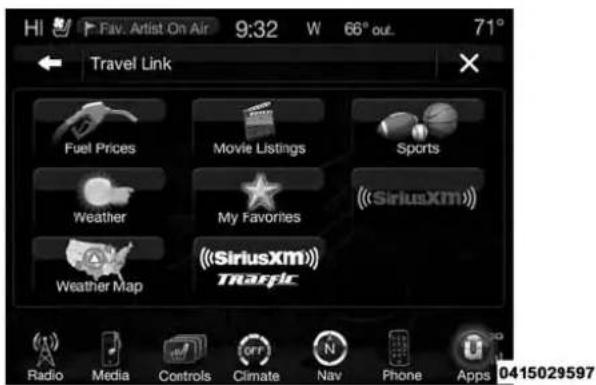
SiriusXMTravelLink™
Additional Information
© 2014 Chrysler Group LLC. All rights reserved. Mopar and Uconnect are registered trademarks and Mopar Owner Connect is a trademark of Chrysler Group LLC. Android is a trademark of Google Inc. SiriusXM and all related marks and logos are trademarks of SiriusXM Radio Inc. Yelp, Yelp logo, Yelp burst and related marks are registered trademarks of Yelp.
Uconnect® System Support:
• U.S. residents call 1-877-855-8400 or visit DriveUconnect.com
- Canadian residents call 1-800-465-2001 (English) or 1-800-387-9983 (French) or visit DriveUconnect.ca
Mon. – Fri., 7:00 am – 12:00 am, ET
Sat., 8:00 am - 10:00 pm, ET
Sun., 9:00 am – 5:00 pm, ET
Uconnect® Access Services Support 1-855-792-4241. Please have your Uconnect® Security PIN ready when you call.
STARTING AND OPERATING
CONTENTS
■STARTING PROCEDURES....330
□Normal Starting. . . . . . . . . . . . . . . . . . . . . . . . . . . . . . . . . . . . . . . . . . . . . 330
□Automatic Transmission....331
☐Extreme Cold Weather (Below -20^ F or -29^ C). .331
□If Engine Fails To Start....331
□After Starting....332
■ENGINE BLOCK HEATER — IF EQUIPPED. . . .333
■AUTOMATIC TRANSMISSION....333
□Key Ignition Park Interlock. . . . . . . . . . . . . . . . . . . . . 335
□Brake/Transmission Shift Interlock System . . .336
□Six-Speed Automatic Transmission — If Equipped .....336
□Stationary Mode....348
□Mobile Mode. .350
■FOUR-WHEEL DRIVE OPERATION — IF EQUIPPED ....351
□Manually Shifted Transfer Case — If Equipped....351
326 STARTING AND OPERATING
□Shifting Procedure — Manually Shifted Transfer Case . . . . . . . . . . . . . . . . . . . . . . . . . . . . . . . . . . . . . . . . . . . . . . . . . . . . . . . . 354
□Transfer Case Position Indicator Light . . . . . .355
□Electronically Shifted Transfer Case (Four-Position Switch) — If Equipped . . . . . . .355
□Shifting Procedure....359
■LIMITED-SLIP DIFFERENTIAL....361
■DRIVING ON SLIPPERY SURFACES....362
□Acceleration....362
□Traction....363
■DRIVING THROUGH WATER....363
□Flowing/Rising Water....363
□Shallow Standing Water....364
■POWER STEERING....365
□Power Steering Fluid Check....366
■PARKING BRAKE....367
□Anti-Lock Brake System (ABS)....371
□Traction Control System (TCS)....372
□Hill Start Assist (HSA) .373
□Electronic Stability Control (ESC) .....375
□ESC Activation/Malfunction Indicator Light And ESC OFF Indicator Light . . . . . . . . . . . . . . . . . . . . . . . . . . . . . . . . . . . . . . . . . . . . . . . . . . . . . . . . . .
□Trailer Sway Control (TSC) .....381
■TIRE SAFETY INFORMATION .....382
STARTING AND OPERATING 327
□Tire Markings....382
□Tire Identification Number (TIN)....386
□Tire Terminology And Definitions....387
□Tire Loading And Tire Pressure....389
■TIRES — GENERAL INFORMATION .....394
□Tire Pressure....394
□Tire Inflation Pressures....395
☐Tire Pressures For High Speed Operation . . . 397
□Tire Maintenance and Replacement .....397
□Radial Ply Tires....398
□Tire Types . . . . . . . . . . . . . . . . . . . . . . . . . . . . . . . . . . . . . . . . . . . . . . . 398
□Run Flat Tires — If Equipped . . . . . . . . . . . . . . . . . . . . . . 400
□Spare Tires — If Equipped .....400
□Tire Spinning....403
□Tread Wear Indicators....403
□Life Of Tire....404
□Replacement Tires....405
■ SUPPLEMENTAL TIRE PRESSURE INFORMATION — IF EQUIPPED....406
■TIRE CHAINS (TRACTION DEVICES) .....407
■TIRE ROTATION RECOMMENDATIONS . . . . .409
□Dual Rear Wheels....410
■TIRE PRESSURE MONITOR SYSTEM (TPMS) . .411
□Base System — If Equipped .....414
□Premium System . . . . . . . . . . . . . . . . . . . . . . . . . . . . . . . . . . . . . . . . . . . 414
☐Tire Pressure Information System (TPIS)
Chassis Cab — If Equipped .....419
328 STARTING AND OPERATING
□General Information....421
■FUEL REQUIREMENTS....421
□5.7L/6.4L Engines . . . . . . . . . . . . . . . . . . . . . . . . . . . . . . . . . . . . . . . . . . . . . 421
□Reformulated Gasoline....422
□Gasoline/Oxygenate Blends....422
□E-85 Usage In Non-Flex Fuel Vehicles .....423
□MMT In Gasoline....423
□Materials Added To Fuel . . . . . . . . . . . . . . . . . . . . . . . . . . . . . . 424
□Fuel System Cautions. . . . . . . . . . . . . . . . . . . . . . . . . . . . . . . . . 424
□Carbon Monoxide Warnings....425
■ADDING FUEL....426
□Loose Fuel Filler Cap Message . . . . . . . . . . . . . . . . . . . . . . . . . . . . . . . . . . . . . . . . . . . . . . . . . . . . . . . . . . 427
■VEHICLE LOADING....427
□Certification Label .....427
■TRAILER TOWING....430
□Common Towing Definitions . . . . . . . . . . . . . . . . 430
□Trailer Hitch Classification....435
□Trailer Towing Weights (Maximum Trailer Weight Ratings)....436
□Trailer And Tongue Weight....436
□Towing Requirements....437
□Towing Tips....446
■SNOWPLOW 448
□Before Plowing....448
□ Snowplow Prep Package Model Availability . . .449
□Over The Road Operation With Snowplow Attached....449
□Operating Tips....450
□General Maintenance....450
■RECREATIONAL TOWING (BEHIND MOTORHOME, ETC.) . . . . . . . . . . . . . . . . . . . . . . . . . . . . . . . . . . . . . . . . . . . . . . . . 451
□ Towing This Vehicle Behind Another Vehicle . . .451
STARTING AND OPERATING 329
□Recreational Towing — Two-Wheel Drive Models....452
□Recreational Towing — Four-Wheel Drive Models . . . . . . . . . . . . . . . . . . . . . . . . . . . . . . . . . . . . . . . . . . . . . . . . . . . . . 453
330 STARTING AND OPERATING
STARTING PROCEDURES
Before starting your vehicle, adjust your seat, adjust both inside and outside mirrors, and fasten your seat belt.
The starter should not be operated for more than 10-second intervals. Waiting a few seconds between such intervals will protect the starter from overheating.
WARNING!
Neverleavechildrenaloneinavehicle,orwith accesstoan unlocked vehicle.Leavingchildrenina vehicleunattendedisdangerousforanumberof reasons.Achildorotherscouldbeseriouslyor fatally injured.Childrenshouldbewarnednotto touchtheparkingbrake,brakepedalortheshift lever/transmissiongearselector.DonotleavetheKey Fobinornearthevehicle,orinalocationaccessible
WARNING!(Continued)
tochildren, and donotleavetheignitionofvehicle equipped with keyless Enter-N-GointheACCor ON/RUNmode. Achildcouldoperatepowerwindows, other controls, ormovethevehicle.
Normal Starting
Normal starting of either a warm or cold engine is obtained without pumping or pressing the accelerator pedal. Cycle the ignition to the START position and release when the engine starts. If the engine fails to start within 10 seconds, cycle the ignition to the OFF position, wait five seconds, then repeat the “Normal Starting” procedure.
(Continued)
Automatic Transmission
Start the engine with the shift lever in the NEUTRAL or PARK. Apply the brake before shifting into any driving range.
NOTE: This vehicle is equipped with at transmission shiftinterlockingsystem. The brake pedal must be pressed to shift out of PARK.
TipStartFeature
Donotpress the accelerator. Cycle the ignition switch briefly to the START position and release it. The starter motor will continue to run but will automatically disengage when the engine is running.
Extreme Cold Weather (Below -20°F or -29°C)
To ensure reliable starting at these temperatures, use of an externally powered electric engine block heater (available from your authorized dealer) is recommended.
If Engine Fails To Start
If the engine fails to start after you have followed the "Normal Starting" procedure, it may be flooded. Push the accelerator pedal all the way to the floor and hold it there while cranking the engine. This should clear any excess fuel in case the engine is flooded.
CAUTION!
Topreventdamagetothestarter, donotcrank the engineformorethan10secondsatatime. Wait10to 15secondsbeforetryingagain.
WARNING!
- Neverpourfuelorotherflammableliquidsinto thethrottlebodyairinletopeninginanattemptto startthevehicle. This could result in a flashfire causing serious personal injury.
- Donotattempttopushortowyourvehicletogetit started. Vehiclesequippedwithanautomatictransmissioncannotbestedthisway.Unburnedfuel couldenterthecatalyticconverterandoncethe enginehasstarted,igniteanddamagetheconverter andvehicle.
- If the vehicle has adischarged battery, booster cables maybe used to obtain a start from abooster battery or the battery in another vehicle. This type of start can be dangerous if done improperly. Refer to "Jump Starting" in "What To Do In Emergencies" for further information.
If the engine has been flooded, it may start to run, but not have enough power to continue running when the ignition button/key is released. If this occurs, continue cranking with the accelerator pedal pushed all the way to the floor. Release the accelerator pedal and the ignition button/key once the engine is running smoothly.
If the engine shows no sign of starting after two 10-second periods of cranking with the accelerator pedal held to the floor, the "Normal Starting" procedure should be repeated.
After Starting
The idle speed is automatically controlled and will decrease as the engine warms up.
ENGINE BLOCK HEATER — IF EQUIPPED
The engine block heater warms the engine, and permits quicker starts in cold weather. Connect the cord to a standard 110-115 Volt AC electrical outlet with a grounded, three-wire extension cord.
GasolineEngineOnly
The engine block heater cord is routed through the grille by the right front tow hook.
It includes a removable cap that is secured by a tethered strap. It also has a c-clip that is used for storage when not in use for the winter months. During winter months, remove the heater cord wiring assembly from itself on the c-clip.
The engine block heater must be plugged in at least one hour to have an adequate warming effect on the engine.
WARNING!
Remembertodisconnecttheengineblockheater cordbeforedriving.Damagetothe110-115Volt electricalcordcouldcauseelectrocution.
AUTOMATIC TRANSMISSION
CAUTION!
Damagetothetransmissionmayoccurifthefollowingprecautionsarenotobserved:
- ShiftintooroutofPARKorREVERSEonlyafter thevehiclehascometoacompletestop.
- DonotshiftbetweenPARK, REVERSE, NEUTRAL, orDRIVEwhentheengineisaboveidlespeed.
- Beforeshiftingintoanygear,makesureyourfoot isfirmlypressingthebrakepedal.
334 STARTING AND OPERATING
NOTE: You must press and hold the brake pedal while shifting out of PARK.
WARNING!
- ItisdangeroustoshiftoutofPARKorNEUTRAL iftheenginespeedishigherthanidlespeed.If yourfootisnotfirmlypressingthebrakepedal,the vehiclecouldacceleratequicklyforwardorinreverse.Youcouldlosecontrolofthevehicleandhit someoneorsomething.Onlyshiftintogearwhen theengineisidlingnormallyandyourfootis firmlypressingthebrakepedal.
(Continued)
WARNING!(Continued)
- Unintendedmovementofvehiclecouldinjure thoseinornearthevehicle.Aswithallvehicles, youshouldneverexitavehiclewhiletheengineis running.Beforeexitingavehicle,alwaysapplythe parkingbrake,shiftthetransmissionintoPARK, turntheengineOFF,andremovetheKeyFob. WhentheignitionisintheLOCK/OFF(keyremoval)position,thetransmissionislockedin PARK,securingthevehicleagainstunwanted movement.
- Whenleavingthevehicle,alwaysmakesurethe ignitionisintheOFFposition,removetheKeyFob fromthevehicle,andlockthevehicle.
(Continued)
WARNING!(Continued)
- Neverleavechildrenaloneinavehicle,orwith accesstoan unlocked vehicle. Allowingchildrento beinavehicleunattendedisdangerousfora numberofreasons.Achildorotherscouldbe seriouslyorfatallyinjured.Childrenshouldbe warnednottotouchtheparkingbrake,brakepedal orthetransmissiongearselector.
- DonotleavetheKeyFobinornearthevehicle(or inalocationaccessibletochildren), anddonot leavetheignition(inavehicleequipped with KeylessEnter-N-Go™)intheACCorON/RUN position. Achildcouldoperatepowerwindows, othercontrols, ormovethevehicle.
Key Ignition Park Interlock
This vehicle is equipped with a Key Ignition Park Interlock which requires the transmission to be in PARK before the ignition switch can be turned to the LOCK/OFF (key removal) position. The Key Fob can only be removed from the ignition when the ignition is in the LOCK/OFF position, and the transmission is locked in PARK whenever the ignition switch is in the LOCK/OFF position.
NOTE: If a malfunction occurs, the system will trap the Key Fob in the ignition switch to warn you that this safety feature is inoperable. The engine can be started and stopped but the Key Fob cannot be removed until you obtain service.
336 STARTING AND OPERATING
Brake/Transmission Shift Interlock System
This vehicle is equipped with a Brake Transmission Shift Interlock system (BTSI) that holds the shift lever in PARK unless the brakes are applied. To shift the transmission out of PARK, the ignition switch must be turned to the ON/RUN position (engine running or not) and the brake pedal must be pressed.
Six-Speed Automatic Transmission — If Equipped
Chassis Cab models (with automatic transmission) may use either the AS66RC transmission (which is equipped with a Power Take-Off (PTO) access cover on the side of the transmission case), or the 66RFE transmission (which has no PTO access cover).
The transmission gear position display (located in the instrument cluster) indicates the transmission gear range. The shift lever is mounted on the right side of the steering column. You must press the brake pedal to move the shift lever out of PARK (refer to "Brake/Transmission Shift Interlock System" in this section). To drive, move the shift lever from PARK or NEUTRAL to the DRIVE position. Pull the shift lever toward you when shifting into RE-VERSE or PARK, or when shifting out of PARK.
The electronically-controlled transmission provides a precise shift schedule. The transmission electronics are self-calibrating; therefore, the first few shifts on a new vehicle may be somewhat abrupt. This is a normal condition, and precision shifts will develop within a few hundred miles (kilometers).
Only shift from DRIVE to PARK or REVERSE when the accelerator pedal is released and the vehicle is stopped. Be sure to keep your foot on the brake pedal when shifting between these gears.
The transmission shift lever has only PARK, REVERSE, NEUTRAL, and DRIVE shift positions. Manual downshifts can be made using the Electronic Range Select
(ERS) shift control (refer to "Electronic Range Select [ERS] Operation" in this section for further information). Pressing the ERS (- / + ) switches (on the shift lever) while in the DRIVE position will select the highest available transmission gear, and will display that gear in the instrument cluster as 1, 2, 3, etc.
GearRanges
DO NOT race the engine when shifting from PARK or NEUTRAL into another gear range.
NOTE: After selecting any gear range, wait a moment to allow the selected gear to engage before accelerating. This is especially important when the engine is cold.
PARK(P)
This range supplements the parking brake by locking the transmission. The engine can be started in this range. Never attempt to use PARK while the vehicle is in motion. Apply the parking brake when leaving the vehicle in this range.
When parking on a level surface, you may shift the transmission into PARK first, and then apply the parking brake.
When parking on a hill, apply the parking brake before shifting the transmission to PARK, otherwise the load on the transmission locking mechanism may make it difficult to move the shift lever out of PARK. As an added precaution, turn the front wheels toward the curb on a downhill grade and away from the curb on an uphill grade.
On four-wheel drive vehicles be sure that the transfer case is in a drive position.
338 STARTING AND OPERATING
WARNING!
- NeverusethePARKpositionasasubstituteforthe parkingbrake.Alwaysapplytheparkingbrake fullywhenparkedtoguardagainstvehiclemovementandpossibleinjuryordamage.
- Yourvehiclecouldmoveandinjureyouandothers ifitisnotcompletelyinPARK.Checkbytryingto movetheshiftleveroutofPARKwiththebrake pedalreleased.Makesurethetransmissionisin PARKbeforeleavingthevehicle.
WARNING!(Continued)
- It is dangerous to shift out of PARK or NEUTRAL if the engines speed is higher than idlespeed. If your foot is not firmly pressing the brake pedal, the vehicle could accelerate quickly forward or in reverse. You could lose control of the vehicle and hit someone or something. Only shift into gear when the engine is idling normally and your foot is firmly pressing the brake pedal.
(Continued)
(Continued)
WARNING!(Continued)
- Unintendedmovementofvehiclecouldinjure thoseinornearthevehicle.Aswithallvehicles, youshouldneverexitavehiclewhiletheengineis running.Beforeexitingavehicle,alwaysapplythe parkingbrake,shiftthetransmissionintoPARK, turntheengineOFF,andremovetheKeyFob. WhentheignitionisintheLOCK/OFF(keyremoval)position,thetransmissionislockedin PARK,securingthevehicleagainstunwanted movement.
- Whenleavingthevehicle,alwaysmakesurethe ignitionisintheOFFposition,removetheKeyFob fromthevehicle,andlockthevehicle.
WARNING!(Continued)
- Neverleavechildrenaloneinavehicle,orwith accesstoan unlocked vehicle. Allowingchildrento beinavehicleunattendedisdangerousfora numberofreasons.Achildorotherscouldbe seriouslyorfatallyinjured.Childrenshouldbe warnednottotouchtheparkingbrake,brakepedal ortheshiftlever.
- DonotleavetheKeyFobinornearthevehicle,(or inalocationaccessibletochildren)anddonot leavetheignition(inavehicleequipped with KeylessEnter-N-Go™)intheACCorON/RUN position.Achildcouldoperatepowerwindows, othercontrols,ormovethevehicle.
(Continued)
CAUTION!
- BeforemovingtheshiftleveroutofPARK,you mustturntheignitionswitchfromtheLOCK/OFF positiontotheON/RUNposition,andalsopress thebrakepedal. Otherwise,damagetotheshift levercouldresult.
- DONOTracetheenginewhenshiftingfrom PARKorNEUTRALintoanothergearrange,asthis candamagethedrivetrain.
The following indicators should be used to ensure that you have engaged the transmission into the PARK position:
- When shifting into PARK, pull the shift lever toward you and move it all the way counterclockwise until it stops.
- Release the shift lever and make sure it is fully seated in the PARK gate.
- Look at the transmission gear position display and verify that it indicates the PARK position.
- With brake pedal released, verify that the shift lever will not move out of PARK.
REVERSE(R)
This range is for moving the vehicle backward. Shift into REVERSE only after the vehicle has come to a complete stop.
NEUTRAL(N)
Use this range when the vehicle is standing for prolonged periods with the engine running. The engine may be started in this range. Apply the parking brake and shift the transmission into PARK if you must leave the vehicle.
WARNING!
DonotcoastinNEUTRALandneverturnoffthe ignitiontocoastdownahill.Theseareunsafe practicesthatlimityourresponsetochangingtraffic orroadconditions.Youmightlosecontrolofthe vehicleandhaveacollision.
CAUTION!
Towingthevehicle,coasting,ordrivingforanyother reasonwiththetransmissioninNEUTRALcancause severetransmissiondamage.Referto"Recreational Towing"in"StartingAndOperating"and"TowingA DisabledVehicle"in"WhatToDoInEmergencies" forfurtherinformation.
DRIVE(D)
This range should be used for most city and highway driving. It provides the smoothest upshifts and downshifts, and the best fuel economy. The transmission automatically upshifts through underdrive first, second, and third gears, direct fourth gear and overdrive fifth and sixth gears. The DRIVE position provides optimum driving characteristics under all normal operating conditions.
When frequent transmission shifting occurs (such as when operating the vehicle under heavy loading conditions, in hilly terrain, traveling into strong head winds, or while towing heavy trailers), use the Electronic Range Select (ERS) shift control (refer to “Electronic Range Select (ERS) Operation” in this section for further information) to select a lower gear range. Under these conditions, using a lower gear range will improve performance and extend transmission life by reducing excessive shifting and heat buildup.
If the transmission temperature exceeds normal operating limits, the powertrain controller will modify the transmission shift schedule and expand the range of torque converter clutch engagement. This is done to prevent transmission damage due to overheating.
If the transmission becomes extremely hot or is in danger of overheating, the "Transmission Temperature Warning Light" may illuminate and the transmission may operate differently until the transmission cools down.
NOTE: Use caution when operating a heavily loaded vehicle at low speeds (such as towing a trailer up a steep grade, or in stop-and-go traffic) during hot weather. In these conditions, torque converter slip can impose a significant additional heat load on the cooling system. Downshifting the transmission to the lowest possible gear (when climbing a grade), or shifting to NEUTRAL (when stopped in heavy traffic) can help to reduce this excess heat generation.
During cold temperatures, transmission operation may be modified depending on engine and transmission temperature as well as vehicle speed. This feature improves warm up time of the engine and transmission to achieve maximum efficiency. Engagement of the torque converter clutch is inhibited until the transmission fluid is warm (refer to the "Note" under "Torque Converter Clutch" in this section). On models with 66RFE transmission, top overdrive gear is also inhibited until the transmission fluid is warm, and during extremely cold temperatures (-16°F [-27°C] or below), operation may briefly be limited to first and direct gears only. On trucks with AS66RC transmission, fifth and sixth gears may be inhibited briefly on cold starts below 41°F (5°C), and during very cold temperatures (-4°F [-20°C] or below), operation may briefly be limited to third gear only. During this condition, the ability of the vehicle to accelerate under heavily loaded conditions may be reduced.
In all cases, normal operation will resume once the transmission temperature has risen to a suitable level.
TransmissionLimpHomeMode
Transmission function is monitored electronically for abnormal conditions. If a condition is detected that could result in transmission damage, Transmission Limp Home Mode is activated. In this mode, the transmission remains in fourth gear (for 66RFE transmission) or third gear (for AS66RC transmission) regardless of which forward gear is selected. If an AS66RC equipped truck enters Limp Home Mode at highway speeds, it will initially engage fifth gear, until the vehicle slows to a speed where third gear can be engaged. PARK, REVERSE, and NEUTRAL will continue to operate. The Malfunction Indicator Light (MIL) may be illuminated. Limp Home Mode allows the vehicle to be driven to an authorized dealer for service without damaging the transmission.
In the event of a momentary problem, the transmission can be reset to regain all forward gears by performing the following steps:
- Stop the vehicle.
- Shift the transmission into PARK.
- Turn the ignition switch to the OFF position.
-
Wait approximately 10 seconds.
-
Restart the engine.
-
Shift into the desired gear range. If the problem is no longer detected, the transmission will return to normal operation.
NOTE: Even if the transmission can be reset, we recommend that you visit your authorized dealer at your earliest possible convenience. Your authorized dealer has diagnostic equipment to determine if the problem could recur.
344 STARTING AND OPERATING
If the transmission cannot be reset, authorized dealer service is required.
ElectronicRangeSelect(ERS)Operation
The Electronic Range Select (ERS) shift control allows the driver to limit the highest available gear when the transmission is in DRIVE. For example, if you shift the transmission into 4 (fourth gear), the transmission will not shift above fourth gear, but will shift through the lower gears normally.
You can switch between DRIVE and ERS mode at any vehicle speed. When the shift lever is in the DRIVE position, the transmission will operate automatically, shifting between all available gears. Tapping the ERS (-) switch will activate ERS mode, display the current gear in the instrument cluster, and maintain that gear as the top available gear. Once in ERS mode, tapping (-) or (+) will change the top available gear.

natural_image
Close-up of a car interior showing a black handle with a white button and arrow pointing to the side panel (no text or symbols visible)ColumnShiftLever
To exit ERS mode, simply press and hold the ERS (+) switch until "D" is once again displayed in the instrument cluster.
WARNING!
Donotdownshiftforadditionalenginebrakingona slipperysurface. Thedrivewheelscouldlosetheir gripandthevehiclecouldskid,causingacollisionor personalinjury.
NOTE: To select the proper gear position for maximum deceleration (engine braking), simply press and hold the ERS (-) switch. The transmission will shift to the range from which the vehicle can best be slowed down.
CAUTION!
When using ERSforengine braking while descending steep grades, be careful not too overspeed the engine. Apply the brakes as needed to prevent engine overspeed.
OverdriveOperation
The automatic transmission includes an electronically controlled Overdrive (fifth and sixth gears). The transmission will automatically shift into Overdrive if the following conditions are present:
- The shift lever is in the DRIVE position.
- The transmission fluid has reached an adequate temperature.
- The engine coolant has reached an adequate temperature.
- Vehicle speed is sufficiently high.
- The TOW/HAUL switch has not been activated.
- The driver is not heavily pressing the accelerator.
346 STARTING AND OPERATING
WhenToUseTOW/HAULMode
When driving in hilly areas, towing a trailer, carrying a heavy load, etc., and frequent transmission shifting occurs, press the TOW/HAUL switch to activate TOW/HAUL mode. This will improve performance and reduce the potential for transmission overheating or failure due to excessive shifting. When operating in TOW/HAUL mode, transmission upshifts are delayed, and the transmission will automatically downshift (for engine braking) when the throttle is closed and/or during steady braking maneuvers.

TOW/HAULSwitch
The "TOW/HAUL Indicator Light" will illuminate in the instrument cluster to indicate that TOW/HAUL mode has been activated. Pressing the switch a second time restores normal operation. Normal operation is always the default at engine start-up. If TOW/HAUL mode is desired, the switch must be pressed each time the engine is started.
WARNING!
Donotusethe"TOW/HAUL"featurewhendriving inicyorslipperyconditions.Theincreasedengine brakingcancausetherearwheelstoslide,andthe vehicletoswingaroundwiththepossiblelossof vehiclecontrol,whichmaycauseanaccidentpossiblyresultinginpersonalinjuryordeath.
TorqueConverterClutch
A feature designed to improve fuel economy has been included in the automatic transmission on your vehicle. A clutch within the torque converter engages automatically at calibrated speeds. This may result in a slightly different feeling or response during normal operation in the upper gears. When the vehicle speed drops or during some accelerations, the clutch automatically disengages.
NOTE:
- The torque converter clutch will not engage (and 66RFE-equipped trucks will not shift to sixth gear), until the transmission fluid and engine coolant are warm [usually after 1 to 3 miles (2 to 5 km) of driving]. Because engine speed is higher when the torque converter clutch is not engaged, it may seem as if the transmission is not shifting properly when cold. This is normal. Using the Electronic Range Select (ERS) shift control, when the transmission is sufficiently warm, will demonstrate that the transmission is able to shift into and out of Overdrive.
- If the vehicle has not been driven for several days, the first few seconds of operation after shifting the transmission into gear may seem sluggish. This is due to the fluid partially draining from the torque converter into the transmission. This condition is normal and will not
cause damage to the transmission. The torque converter will refill within five seconds after starting the engine.
This vehicle when equipped with PTO Prep and the AS66RC automatic six-speed, will allow for an aftermarket upfit with a transmission driven PTO (power take off). The customer will have the ability to operate the PTO in either a “stationary” or “mobile” mode. The vehicles will be factory set to the “stationary” mode. To select ‘mobile mode’ You will need to enter the commercial vehicle menu on the EVIC/DID screen and select mobile PTO mode. Details of the PTO selection modes and further PTO information is available at the Ram Truck Bodybuilders web site. www.rambodybuilder.com
AS66RCSix-SpeedAutomaticTransmissionOnly
The PTO drive gear (part of the AS66RC) operates at torque converter turbine speed. The turbine speed will be less than engine speed when the torque converter clutch is not engaged and will be same as engine speed when the torque converter clutch is engaged.
Stationary Mode
To operate the PTO in this mode the vehicle must meet the following conditions:
- Be in PARK position (vehicles equipped with automatic transmission.)
- PTO switch has been activated.
- Parking brake applied (vehicles equipped with manual transmission).
-
Brake pedal must not be applied.
-
Vehicle engine must be running.
- No vehicle, brake or clutch switch faults present.
- PTO must be correctly installed using the vehicle provided circuits.
The Electronic Vehicle Information Center (EVIC) or Driver Information Display (DID) will display a "PTO On"message for five seconds if the above conditions are met. Otherwise, the EVIC/DID will display a message "To Operate PTO Shift To Park"indicating what operator action should be taken to engage the PTO mode.
The customer has the choice to operate the PTO by utilizing the cruise control switches or by utilizing a remote control (provided by the PTO supplier). To operate the feature using the cruise control switches, the customer must first activate the PTO switch which will turn on the PTO. In order to increase or decrease the engine idle speed, to optimize the PTO function, the "RESUME/ACCEL" and "DECEL" cruise switches can
be used respectively. To disengage PTO operation and return to "standard vehicle operation" simply toggle the PTO switch to the OFF position.
The torque converter clutch (TCC) will automatically engage at engine speeds above 1,200 RPM (engine speed) in PTO stationary mode. Once engaged, the TCC will remain applied and will not disengage until the engine speed falls below 1,000 RPM. TCC engagement is desirable for certain types of PTO applications (Automatic Transmission Only).
To operate the PTO via a remote switch, the customer must make sure the above conditions are met. It is vital for proper operation that the PTO and remote have been installed correctly, paying special attention to ensure the vehicle provided wiring has been connected properly. This is the responsibility of the installer of the PTO and switches/remote system. It is the responsibility of the PTO manufacturer to ensure that their electrical (switches
350 STARTING AND OPERATING
and remote) system is compatible with the vehicle's electrical architecture and software functionality.
NOTE: Single set speed can be programmed via the PTO menu on the EVIC/DID screen. Further details are available at the Ram Truck Bodybuilders web site. www.rambodybuilder.com www.ramtrucks.com.
Mobile Mode
To operate the PTO in this mode the vehicle must meet the following conditions:
- Mobile mode is activated via the menu on the EVIC/DID screen.
•(ON/OFF) switch has been activated. - Vehicles with automatic transmission must be in PARK or DRIVE.
-
Parking brake must not be applied.
-
Brake pedal must not be applied.
- No vehicle, brake or clutch switch faults present.
- Vehicle engine must be running.
- PTO must be correctly installed using the vehicle provided circuits.
The customer may choose to use the PTO while the vehicle is moving. To do so, the PTO function must be activated prior to taking the vehicle out of PARK. This is accomplished by activating the upfitter-provided PTO on/off switch. At this point, the customer may place the vehicle in a forward or reverse gear and have PTO operation once the vehicle begins to move. To disengage PTO operation and return to “standard vehicle operation” simply toggle the on/off switch to the OFF position.
NOTE: For application specific information with respect to PTO and pump requirements and additional vehicle information (wiring schematics, preset idle values, engine speed limits, and vehicle hardware and software requirements) please refer to the Body Builders Guide by accessing www.rambodybuilder.com and choosing the appropriate links.
Four-wheel drive trucks are equipped with either a manually shifted transfer case or an electronically shifted transfer case. Refer to the operating instructions for your transfer case, located in this section for further information.
Manually Shifted Transfer Case — If Equipped
The transfer case provides four mode positions.
- Two-wheel drive high range (2H)
• Four-wheel drive high range (4H)
- Neutral (N)
- Four-wheel drive low range (4L)
This transfer case is intended to be driven in the 2H position for normal street and highway conditions such as dry, hard surfaced roads.
When additional traction is required, the 4H and 4L positions can be used to lock the front and rear drive-shafts together and force the front and rear wheels to rotate at the same speed. This is accomplished by simply moving the shift lever to the desired positions once the appropriate speed and gear requirements are met refer to "Shifting Procedure – Manually Shifted Transfer Case" in this section for further information. The 4H and 4L positions are intended for loose, slippery road surfaces only. Driving in the 4H and 4L positions on dry, hard surfaced roads may cause increased tire wear and damage to the driveline components.
352 STARTING AND OPERATING
The “Transfer Case Position Indicator Light” in the instrument cluster will alert the driver that the vehicle is in four-wheel drive and that the front and rear drive-shafts are locked together. This light will illuminate when the transfer case is shifted into either the 4H or 4L position. There is no light for the 2H or NEUTRAL positions on some models.
When operating your vehicle in 4L, the engine speed is approximately three times that of the 2H or 4H positions at a given road speed. Take care not to overspeed the engine and do not exceed 25 mph (40 km/h).
Proper operation of four-wheel drive vehicles depends on tires of equal size, type and circumference on each wheel. Any difference will adversely affect shifting and can cause damage to the drivetrain.
NOTE: Do not attempt to make a shift while only the front or rear wheels are spinning. The front and rear driveshaft speeds must be equal for the shift to take place. Shifting while only the front or rear wheels are spinning can cause damage to the transfer case.
Because four-wheel drive provides improved traction, there is a tendency to exceed safe turning and stopping speeds. Do not go faster than road conditions permit.
NOTE: Delayed shifts out of four-wheel drive may be experienced due to uneven tire wear, low or uneven tire pressures, excessive vehicle loading, or cold temperatures.
WARNING!
Youorotherscouldbeinjuredorkilledifyouleave thevehicleunattendedwiththetransfercaseinthe
(Continued)
WARNING!(Continued)
NEUTRALpositionwithoutfirstfullyengagingthe parkingbrake. ThetransfercaseNEUTRALposition disengagesboththefrontandreadriveshaftsfrom thepowertrainandwillallowthevehicletoroll, evenifthetransmissionisinPARK. Theparking brakeshouldalwaysbeappliedwhenthedriveris notinthevehicle.
For additional information on the appropriate use of each transfer case mode position, see the information below:
2H
Rear-Wheel Drive High Range — This range is for normal street and highway driving on dry hard surfaced roads.
4H
Four-Wheel Drive High Range — This range locks the front and rear driveshafts together forcing the front and rear wheels to rotate at the same speed. Additional traction for loose, slippery road surfaces only.
Neutral(N)
Neutral — This range disengages the front and rear driveshafts from the powertrain. To be used for flat towing behind another vehicle. Refer to “Recreational Towing” in “Starting and Operating” for further information.
4L
Four-Wheel Drive Low Range — This range locks the front and rear driveshafts together forcing the front and rear wheels to rotate at the same speed. Additional traction and maximum pulling power for loose, slippery road surfaces only. Do not exceed 25 mph (40 km/h).
CAUTION!
Donotuse4L(Low)rangewhenoperatingthe vehicleondrypavement.Drivelinehardwaredamagecanresult.
Shifting Procedure — Manually Shifted Transfer Case
2HTo4H
Shifting between 2H and 4H can be made with the vehicle stopped or in motion. If the vehicle is in motion, shifts can be made up to 55 mph (88 km/h). With the vehicle in motion, the transfer case will engage/disengage faster if you momentarily release the accelerator pedal after completing the shift. Apply a constant force when shifting the transfer case lever.
2HOr4HTo4L
With the vehicle rolling at 2 to 3 mph (3 to 5 km/h), shift the transmission into NEUTRAL. While the vehicle is coasting at 2 to 3 mph (3 to 5 km/h), shift the transfer case lever firmly to the desired position. Do not pause in transfer case NEUTRAL.
NOTE:
- Pausing in transfer case NEUTRAL in vehicles equipped with an automatic transmission may require shutting the engine OFF to avoid gear clash while completing the shift. If difficulty occurs, shift the transmission into NEUTRAL, hold foot on brake, and turn the engine OFF. Make shift to the desired mode.
- Shifting into or out of 4L is possible with the vehicle completely stopped, however difficulty may occur due to the mating clutch teeth not being properly aligned. Several attempts may be required for clutch teeth
STARTING AND OPERATING 355
alignment and shift completion to occur. The preferred method is with the vehicle rolling 2 to 3 mph (3 to 5 km/h). Avoid attempting to engage or disengage 4L with the vehicle moving faster than 2 to 3 mph (3 to 5 km/h).
- Do not attempt to shift into or from 4L while the transmission is in gear.
Transfer Case Position Indicator Light
The "Transfer Case Position Indicator Light" in the instrument cluster is used to alert the driver that the front axle is fully engaged and all four wheels are driving.
Electronically Shifted Transfer Case (Four-Position Switch) — If Equipped
This is an electronic shift transfer case and is operated by the 4WD Control Switch (Transfer Case Switch), which is located on the instrument panel.
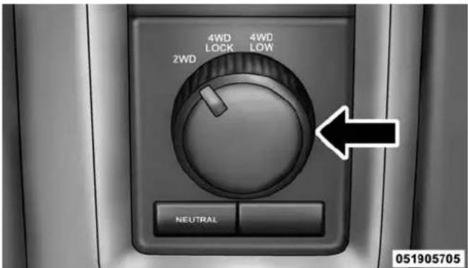
TransferCaseSwitch(Four-Position)
This electronically shifted transfer case provides four mode positions:
- Two-wheel drive high range (2WD)
- Four-wheel drive lock range (4WD LOCK)
- Four-wheel drive low range (4WD LOW)
• Neutral (NEUTRAL)
356 STARTING AND OPERATING
This electronically shifted transfer case is designed to be driven in the two-wheel drive position (2WD) for normal street and highway conditions on dry, hard surfaced roads.
When additional traction is required, the transfer case 4WD LOCK and 4WD LOW positions can be used to maximize torque to the front driveshaft, forcing the front and rear wheels to rotate at the same speed. This is accomplished by rotating the 4WD Control Switch to the desired position. Refer to "Shifting Procedure" in this section for specific shifting instructions. The 4WD LOCK and 4WD LOW positions are designed for loose, slippery road surfaces only. Driving in the 4WD LOCK and 4WD LOW positions on dry hard surfaced roads may cause increased tire wear and damage to the driveline components.
NOTE: The transfer case NEUTRAL position is selected by pressing the button located on the lower left hand corner of the 4WD Control Switch. The transfer case NEUTRAL position is to be used for recreational towing only. Refer to "Recreational Towing" in "Starting and Operating" for further information.
TransferCasePositionIndicatorLights
The Transfer Case Position Indicator Lights (4WD and 4LOW) are located in the instrument cluster and indicate the current and desired transfer case selection. When you select a different transfer case position, the indicator lights will do the following:
IfAllShiftConditionsAreMet:
- The current position indicator light will turn OFF.
-
The selected position indicator light will flash until the transfer case completes the shift.
-
When the shift is complete, the indicator light for the selected position will stop flashing and remain ON.
IfOneOrMoreShiftConditionsAreNotMet:
- The indicator light for the current position will remain ON.
- The newly selected position indicator light will continue to flash.
- The transfer case willnotshift.
NOTE: Before retrying a selection, make certain that all the necessary requirements for selecting a new transfer case position have been met. To retry the selection, turn the control knob back to the current position, wait five seconds, and retry selection. To find the shift requirements, refer to the "Shifting Procedure" for your transfer case, located in this section.
The "SVC 4WD Warning Light" monitors the electronic shift four-wheel drive system. If this light remains on after engine start up or illuminates during driving, it means that the four-wheel drive system is not functioning properly and that service is required.
WARNING!
Alwaysengagetheparkingbrakewhenpowering downthevehicleifthe"SVC4WDWarningLight"is illuminated. Notengagingtheparkingbrakemay allowthevehicletoroll,whichmaycausepersonal injury.
NOTE: Do not attempt to make a shift while only the front or rear wheels are spinning, as this can cause damage to driveline components.
When operating your vehicle in 4WD LOW, the engine speed is approximately three times that of the 2WD or
358 STARTING AND OPERATING
4WD LOCK positions at a given road speed. Take care not to overspeed the engine and do not exceed 25 mph (40 km/h).
Proper operation of four-wheel drive vehicles depends on tires of equal size, type and circumference on each wheel. Any difference in tire size can cause damage to the drivetrain.
Because four-wheel drive provides improved traction, there is a tendency to exceed safe turning and stopping speeds. Do not go faster than road conditions permit.
WARNING!
Youorotherscouldbeinjuredorkilledifyouleave thevehicleunattendedwiththetransfercaseinthe NEUTRALpositionwithoutfirstfullyengagingthe parkingbrake.ThetransfercaseNEUTRALposition
(Continued)
WARNING!(Continued)
disengagesboththefrontandredriveshaftsfrom thepowertrainandwillallowthevehicletoroll, evenifthetransmissionisinPARK.Theparking brakeshouldalwaysbeappliedwhenthedriveris notinthevehicle.
For additional information on the appropriate use of each transfer case mode position, see the information below:
2WD
Rear Wheel Drive High Range — This range is for normal street and highway driving on dry, hard surfaced roads.
4WDLOCK
Four-Wheel Drive Lock Range — This range maximizes torque to the front driveshaft, forcing the front and rear wheels to rotate at the same speed. This range provides additional traction for loose, slippery road surfaces only.
4WDLOW
Four-Wheel Drive Low Range — This range provides low speed four-wheel drive. It maximizes torque to the front driveshaft, forcing the front and rear wheels to rotate at the same speed. This range provides additional traction and maximum pulling power for loose, slippery road surfaces only. Do not exceed 25 mph (40 km/h).
NEUTRAL(N)
Neutral — This range disengages both the front and rear driveshafts from the powertrain. To be used for flat towing behind another vehicle. Refer to “Recreational Towing” in “Starting and Operating” for further information.
Shifting Procedure
NOTE:
- If any of the requirements to select a new transfer case position have not been met, the transfer case will not shift. The position indicator light for the previous position will remain ON and the newly selected position indicator light will continue to flash until all the requirements for the selected position have been met. To retry a shift: return the control knob back to the original position, make certain all shift requirements have been met, wait five seconds and try the shift again.
- If all the requirements to select a new transfer case position have been met, the current position indicator light will turn OFF, the selected position indicator light will flash until the transfer case completes the shift. When the shift is complete, the position indicator light for the selected position will stop flashing and remain ON.
360 STARTING AND OPERATING
2WDTo4WDLOCK
Rotate the 4WD control switch to the desired position. Shifts between 2WD and 4WD LOCK can be done with the vehicle stopped or in motion. With the vehicle in motion, the transfer case will engage/disengage faster if you momentarily release the accelerator pedal after turning the control switch. If the vehicle is stopped, the ignition switch must be in the ON position with the engine either running or off. This shift cannot be completed if the ignition switch is in the ACC position.
NOTE: The four-wheel drive system will not allow shifts between 2WD/4WD LOCK if the front and/or rear wheels are spinning (no traction). In this situation, the selected position indicator light will flash and the original position indicator light will remain ON. At this time, reduce speed and stop spinning the wheels to complete the shift.
2WDOr4WDLOCKTo4WDLOW
NOTE: When shifting into or out of 4WD LOW some gear noise may be heard. This noise is normal and is not detrimental to the vehicle or occupants.
Shifting can be performed with the vehicle rolling 2 to 3 mph (3 to 5 km/h) or completely stopped. You can use either of the following procedures:
PreferredProcedure
- With the engine running, slow the vehicle to 2 to 3 mph (3 to 5 km/h).
- Shift the transmission into NEUTRAL.
- While still rolling, rotate the transfer case control switch to the desired position.
- After the desired position indicator light is ON (not flashing), shift the transmission back into gear.
AlternateProcedure
- Bring the vehicle to a complete stop.
- With the ignition switch in the ON position and the engine running, shift the transmission into NEUTRAL.
- Rotate the transfer case control switch to the desired position.
- After the desired position indicator light is ON (not flashing), shift the transmission back into gear.
NOTE:
- If Steps 1 or 2 of either the Preferred or Alternate Procedure are not satisfied prior to attempting the shift, then the desired position indicator light will flash continuously while the original position indicator light is ON, until all requirements have been met.
- The ignition switch must be in the ON position for a shift to take place and for the position indicator lights to be operable. If the ignition switch is not in the ON position, the shift will not take place and no position indicator lights will be on or flashing.
LIMITED-SLIP DIFFERENTIAL
The limited-slip differential provides additional traction on snow, ice, mud, sand and gravel, particularly when there is a difference between the traction characteristics of the surface under the right and left rear wheels. During normal driving and cornering, the limited-slip unit performs similarly to a conventional differential. On slippery surfaces, however, the differential delivers more of the driving effort to the rear wheel having the better traction.
The limited-slip differential is especially helpful during slippery driving conditions. With both rear wheels on a slippery surface, a slight application of the accelerator
will supply maximum traction. When starting with only one rear wheel on an excessively slippery surface, slight momentary application of the parking brake may be necessary to gain maximum traction.
WARNING!
Onvehiclesequippedwithalimited-slipdifferential neverruntheenginewithonerearwheeloffthe groundsincethevehiclemaydrivethroughtherear wheelremainingontheground.Youcouldlose controlofthevehicle.
Care should be taken to avoid sudden accelerations when both rear wheels are on a slippery surface. This could cause both rear wheels to spin, and allow the vehicle to slide sideways on the crowned surface of a road or in a turn.
DRIVING ON SLIPPERY SURFACES
Acceleration
Rapid acceleration on snow covered, wet, or other slippery surfaces may cause the driving wheels to pull erratically to the right or left. This phenomenon occurs when there is a difference in the surface traction under the rear (driving) wheels.
WARNING!
Rapidacceleration on slipperysurfaces is dangerous. Unequaltraction can cause sudden pulling of therear wheels. You could lose control of the vehicle and possibly have a collision. Accelerates slowly and carefully whenever there is likely to be poor traction (ice, snow, wet mud, looses and, etc.).
Traction
When driving on wet or slushy roads, it is possible for a wedge of water to build up between the tire and road surface. This is known as hydroplaning and may cause partial or complete loss of vehicle control and stopping ability. To reduce this possibility, the following precautions should be observed:
- Slow down during rainstorms or when the roads are slushy.
- Slow down if the road has standing water or puddles.
- Replace tires when tread wear indicators first become visible.
- Keep tires properly inflated.
- Maintain sufficient distance between your vehicle and the vehicle in front of you to avoid a collision in a sudden stop.
Your vehicle may be equipped with a Limited Slip Differential (LSD) that reduces, but does not eliminate, the amount of wheel slip across a given axle for improved handling.
DRIVING THROUGH WATER
Driving through water more than a few inches/centimeters deep will require extra caution to ensure safety and prevent damage to your vehicle.
Flowing/Rising Water
WARNING!
Donotdriveonoracrossaroadorpathwherewater isflowingand/orrising(asinstormrun-off).Flowingwatercanwearawaytheroadorpath'ssurface andcauseyourvehicletosinkintodeeperwater. Furthermore,flowingand/orrisingwatercancarry
(Continued)
WARNING!(Continued)
yourvehicleawayswiftly.Failuretofollowthis warningmayresultininjuriesthatareseriousor fataltoyou,yourpassengers,andothersaroundyou.
Shallow Standing Water
Although your vehicle is capable of driving through shallow standing water, consider the following Cautions and Warnings before doing so.
WARNING!
- Drivingthroughstandingwaterlimitsyourvehicle'stractioncapabilities.Donotexceed5mph (8km/h)whendrivingthroughstandingwater.
(Continued)
WARNING!(Continued)
- Drivingthroughstandingwaterlimitsyourvehicle'sbrakingcapabilities,whichincreasesstoppingdistances.Therefore,afterdrivingthroughstandingwater,driveslowlyandlightlypressonthebrakepedalseveraltimestodrythebrakes.
- Failuretofollowthesewarningsmayresultin injuriesthatareseriousorfataltoyou,yourpassengers,andothersaroundyou.
CAUTION!
- Alwayscheckthedepthofthestandingwater beforedrivingthroughit.Neverdrivethrough standingwaterthatisdeeperthanthebottomof thetirerimsmountedonthevehicle.
(Continued)
CAUTION!(Continued)
- Determinetheconditionoftheroadorthepath thatisunderwaterandifthereareanyobstaclesin thewaybeforedrivingthroughthestandingwater.
- Donotexceed5mph(8km/h)whendriving throughstandingwater.Thiswillminimizewave effects.
- Drivingthroughstandingwatermaycausedamage toyourvehicle'sdrivetraincomponents.Always inspectyourvehicle'sfluids(i.e.,engineoil,transmission,axle,etc.)forsignsofcontamination(i.e., fluidthatismilkyorfoamyinappearance)after drivingthroughstandingwater.Donotcontinueto operatethevehicleifanyfluidappearscontaminated,asthismayresultinfurtherdamage.Such damageisnotcoveredbytheNewVehicleLimited Warranty.
CAUTION!(Continued)
- Gettingwaterinsideyourvehicle'senginecan causeittolockupandstallout,andcauseserious internaldamagetotheengine.Suchdamageisnot coveredbytheNewVehicleLimitedWarranty.
POWER STEERING
The standard power steering system will give you good vehicle response and increased ease of maneuverability in tight spaces. The system will provide mechanical steering capability if power assist is lost.
If for some reason the power assist is interrupted, it will still be possible to steer your vehicle. Under these conditions, you will observe a substantial increase in steering effort, especially at very low vehicle speeds and during parking maneuvers.
(Continued)
366 STARTING AND OPERATING
NOTE:
- Increased noise levels at the end of the steering wheel travel are considered normal and do not indicate that there is a problem with the power steering system.
- Upon initial start-up in cold weather, the power steering pump may make noise for a short amount of time. This is due to the cold, thick fluid in the steering system. This noise should be considered normal, and it does not in any way damage the steering system.
CAUTION!
Prolongedoperationofthesteeringsystemattheend ofthesteeringwheeltravelwillincreasethesteering fluidtemperatureanditshouldbeavoidedwhen possible.Damagetothepowersteeringpumpmay occur.
Power Steering Fluid Check
Checking the power steering fluid level at a defined service interval is not required. The fluid should only be checked if a leak is suspected, abnormal noises are apparent, and/or the system is not functioning as anticipated. Coordinate inspection efforts through an authorized dealer.
CAUTION!
Donotusechemicalflushesinyourpowersteering systemasthechemicalscandamageyourpower steeringcomponents.Suchdamageisnotcoveredby theNewVehicleLimitedWarranty.
WARNING!
Fluidlevelshouldbecheckedonalevelsurfaceand withtheengineofftopreventinjuryfrommoving partsandtoensureaccuratefluidlevelreading.Do notoverfill.Useonlymanufacturer'srecommended powersteeringfluid.
If necessary, add fluid to restore to the proper indicated level. With a clean cloth, wipe any spilled fluid from all surfaces. Refer to "Fluids, Lubricants, and Genuine Parts" in "Maintaining Your Vehicle" for further information.
PARKING BRAKE
Before leaving the vehicle, make sure that the parking brake is fully applied, the engine is off and the Key Fob is removed from the ignition switch. Also, be certain to leave an automatic transmission in PARK, or manual transmission in REVERSE or first gear.
The foot operated parking brake is located below the lower left corner of the instrument panel. To apply the parking brake, firmly push the parking brake pedal fully. To release the parking brake, pull the parking brake release handle.
368 STARTING AND OPERATING

natural_image
Interior view of a car's seat and dashboard area showing a parking slot and foot pusher (no text or symbols visible)ParkingBrakeRelease
When the parking brake is applied with the ignition switch ON, the "Brake Warning Light" in the instrument cluster will illuminate.
NOTE:
- When the parking brake is applied and the automatic transmission is placed in gear, the "Brake Warning Light" will flash. If vehicle speed is detected, a chime will sound to alert the driver. Fully release the parking brake before attempting to move the vehicle.
- This light only shows that the parking brake is applied. It does not show the degree of brake application.
When parking on a hill, it is important to turn the front wheels toward the curb on a downhill grade and away from the curb on an uphill grade. For vehicles equipped with an automatic transmission, apply the parking brake before placing the shift lever in PARK, otherwise the load on the transmission locking mechanism may make it difficult to move the shift lever out of PARK.
The parking brake should always be applied whenever the driver is not in the vehicle.
WARNING!
- Neverleavechildrenaloneinavehicle,orwith accesstuan unlocked vehicle. Allowing childrento beinavehicleunattended is dangerous for a number of reasons. Achildor others could be seriously or fatally injured. Children should be warned not to touch the parking brake, brake pedal ortheshift lever.
- DonotleavetheKeyFobinornethevehicle,or inalocationaccessibletochildren,anddonot leavetheignitionofavehicleequippedwith KeylessEnter-N-Go™intheACCorON/RUN mode.Achildcouldoperatepowerwindows,other controls,ormovethevehicle.
WARNING!(Continued)
- Besuretheparkingbrakeisfullydisengaged beforedriving;failuretodosocanleadtobrake failureandacollision.
- Alwaysfullyapplytheparkingbrakewhenleavingyourvehicleoritmayrollandcausedamageor injury. Also, becertaintoleaveanautomatictransmissioninPARK, amanualtransmissioninREVERSEorfirstgear. Failuretodosomaycausethe vehicletorollandcausedamageorinjury.
CAUTION!
If the "BrakeWarningLight" remains on with the parkingbrakereleased, abrakesystemmalfunction is indicated. Havethebrakesystemserviced by an authorized dealer immediately.
(Continued)
370 STARTING AND OPERATING
BRAKE SYSTEM
If power assist is lost for any reason (for example, repeated brake applications with the engine off), the brakes will still function. However, you will experience a substantial increase in braking effort to stop the vehicle.
If either the front or rear hydraulic system loses normal braking capability, the remaining system will still function with some loss of overall braking effectiveness. This will be evident by increased pedal travel during application, greater pedal force required to slow or stop, and activation of the “Brake Warning Light” and the “ABS Warning Light” (if equipped) during brake use.
The brake system power assist is provided by a hydro-boost unit which shares fluid with the power steering system. You may experience some clicking or hissing noises from the hydro-boost system during hard braking conditions.
NOTE: Under cold temperatures, pedal effort will be higher than normal until the power steering fluid reaches operating temperature.
Hydraulic Brake Assist
The brake system power assist is provided by a hydro-boost unit which shares fluid with the power steering system. You may experience some clicking or hissing noises from the hydro-boost system during hard braking conditions.
NOTE: Under cold temperatures, pedal effort will be higher than normal until the power steering fluid reaches operating temperature.
Your vehicle is equipped with an advanced electronic brake control system that includes Anti-Lock Brake System (ABS), Traction Control System (TCS), Brake Assist System (BAS), Electronic Roll Mitigation (ERM), Hill Start Assist (HSA), Electronic Stability Control (ESC), Trailer Sway Control (TSC) and Hill Decent Control (HDC [Power Wagon only]). All of the systems work together to enhance vehicle stability and control in various driving conditions, and are commonly referred to as ESC.
Anti-Lock Brake System (ABS)
The Four-Wheel Anti-Lock Brake System (ABS) is designed to aid the driver in maintaining vehicle control under adverse braking conditions. The system operates with a separate computer to modulate hydraulic pressure to prevent wheel lockup and help avoid skidding on slippery surfaces.
The system's pump motor runs during an ABS stop to provide regulated hydraulic pressure. The pump motor makes a low humming noise during operation. This is normal.
The ABS conducts a low-speed selftest at about 10 mph (16 km/h). If you have your foot lightly on the brake while this test is occurring, you may feel slight pedal movement. The movement can be more apparent on ice and snow. This is normal.
When you are in a severe braking condition involving use of the ABS, you will experience some pedal drop as the vehicle comes to a complete stop. This is the result of the system reverting to the base brake system and is normal.
Engagement of the ABS may be accompanied by a pulsing sensation. You may also hear a clicking noise. These occurrences are normal, and indicate that the system is functioning.
WARNING!
- Pumpingoftheanti-lockbrakeswilldiminish theireffectivenessandmayleadtoacollision. Pumpingmakethestoppingdistancelonger.Just pressfirmlyonyourbrakepedalwhenyouneedto slowdownorstop.
- The Anti-Lock Brake System (ABS) cannot prevent thenaturallawsof physics from acting on the vehicle, nor can it increase braking or steering efficiency beyond that afforded by the condition of the vehicle brakes and tires or the traction afforded.
- The ABScannotpreventcollisions, including those resulting from excessivespeedinturns, following another vehicle to closely, or hydroplaning.
- The capabilities of an ABS-equipped vehicle must never be exploited in areckless or dangerous manner which could jeopardize the user's safety or the safety of others.
ABSWarningLight
The ABS includes an amber warning light. When the light is illuminated, the ABS is not functioning. The system reverts to standard, non-anti-lock brakes.
Traction Control System (TCS)
The TCS monitors the amount of wheel spin of each of the driven wheels. If wheel spin is detected, brake pressure is applied to the slipping wheel(s), and engine power is reduced to provide enhanced acceleration and stability. A feature of the TCS system, Brake Limited Differential (BLD), controls the wheel spin across a driven axle. If one wheel on a driven axle is spinning faster than the other, the system will apply the brake of the spinning wheel. This will allow more engine torque to be applied to the wheel that is not spinning. This feature remains active even if TCS and ESC are in the "Partial Off" mode. Refer to "Electronic Stability Control (ESC)" in this section of this manual. This brake pressure
modulation transfers drive torque from slipping to non-slipping wheels to provide optimal forward traction.
Hill Start Assist (HSA)
The HSA system is designed to assist the driver in launching a vehicle on an incline. HSA will maintain the level of brake pressure the driver inputs for a short duration once the driver takes his foot off of the brake pedal. If the driver does not apply the throttle during this short duration, the system will release brake pressure and the vehicle will roll down the incline. The system will release brake pressure in proportion to the amount of throttle applied.
During operation, HSA will activate the brake control system and a clicking noise may occur. If your foot is on the brake pedal during operation you may feel a slight pedal movement. The clicking and pedal movement is normal and both will stop when HSA becomes inactive.
HSAAActivationCriteria
The following criteria must be met in order for HSA to activate:
- Vehicle must be stopped
- Vehicle must be on an approximate 7% or greater incline
- Gear selection matches vehicle uphill direction (i.e., vehicle facing uphill is in forward gear; vehicle backing uphill is in REVERSE gear).
WARNING!
Theremaybesituationsonminorhillswithloaded vehicleorwhilepullingatrailerwherethesystem willnotactivateandslightrollingmayoccur,which couldcauseacollisionwithanothervehicleorobject. Alwaysrememberthedriverisresponsibleforbrakingthevehicle.
The system will only work if the intended direction of the vehicle and vehicle gear match. For example, if the intended direction is forward up a hill and the vehicle is in DRIVE and the activation criteria are met, HSA will activate.
The system will work in REVERSE and all forward gears, and will not activate if the vehicle is placed in NEUTRAL.
TowingAndHaulingWithHSA
The HSA system does not know if your vehicle is loaded or towing a trailer unless the TOW/HAUL switch, located on the center stack, is selected. When activated, the "TOW/HAUL Indicator Light" will illuminate in the instrument cluster. Refer to "Automatic Transmission" in "Starting and Operating" for further information. In order to accommodate the extra weight entailed under towing and hauling conditions and to increase driver comfort while launching on a hill, the system recognizes when the TOW/HAUL switch is activated and compensates by releasing brake pressure at a slower rate while throttle is applied in order to prevent the vehicle from rolling down the hill.
WARNING!
- If you use a trailer brake controller with your trailer, your trailer brakes may be activated and deactivated with the brakes switch. If so, when the brake pedal is released, there may not been enough brake pressure to hold the vehicle and trailer on a hill and this could cause a collision with another vehicle or object behind you. In order to avoid rolling down the inclinewhileresuming acceleration, manually activate the trailer brake or apply more vehicle brake pressure prioritoreleasing the brake pedal. Always remember the driver responsible for braking the vehicle.
(Continued)
WARNING!(Continued)
- HSAisnotaparkingbrake. If you stop the vehicle on a hill without putting the transmission in PARK or using the parking brake, it will rolldown the incline and could collidewith another vehicle, object person, and causes serious or fatal injury. Always remember the parking brakewhile parking on a hill and that the driver is responsible for braking the vehicle.
HSAOff
HSA is a Customer Programmable Feature in the EVIC/DID. If you wish to turn off the HSA feature, refer to "Electronic Vehicle Information Center (EVIC)/Driver Information Display (DID)" in "Understanding Your Instrument Panel" for further information.
Electronic Stability Control (ESC)
The ESC system enhances directional control and stability of the vehicle under various driving conditions. ESC corrects for oversteering or understeering of the vehicle by applying the brake of the appropriate wheel to assist in counteracting the oversteer or understeer condition. Engine power may also be reduced to help the vehicle maintain the desired path.
ESC uses sensors in the vehicle to determine the vehicle path intended by the driver and compares it to the actual path of the vehicle. When the actual path does not match the intended path, ESC applies the brake of the appropriate wheel to assist in counteracting the oversteer or understeer condition.
• Oversteer - when the vehicle is turning more than appropriate for the steering wheel position.
- Understeer - when the vehicle is turning less than appropriate for the steering wheel position.
WARNING!
ElectronicStabilityControl(ESC) cannot prevent the naturallawsofphysicsfromactingonthevehicle, norcanitincreasethetractionaffordedbyprevailing roadconditions. ESC cannot prevent accidents, including those resulting from excessivespeedin turns, driving on very slippery surfaces, or hydroplaning. ESC also cannot prevent accidents resulting from loss of vehicle contro duetoin appropriate driver input for the conditions. Only as safe, attentive, and skillful driver can prevent accidents. The capabilities of an ESC equipped vehicle must never be exploited in areckless or dangerous manner which could jeopardize the user's safety or the safety of others.
AllTwo-WheelDriveVehiclesAndFour-Wheel DriveVehiclesIn2WD,4WDAUTO,Or4WD LOCKModesCanChooseTheFollowingESC OperatingModes:
ESCON
This is the normal operating mode for ESC in 2WD/4WD AUTO/4WD LOCK modes and in 2WD vehicles. Whenever the vehicle is started or the transfer case (if equipped) is shifted from 4WD LOW or Neutral, back to 4WD LOCK or 4WD AUTO, the ESC system will be in this mode. This mode should be used for almost all driving situations. ESC should only be turned to "ESC Partial Off" or "ESC Full Off" for specific reasons as noted below.
ESCPartialOff
This mode is entered by momentarily pressing the "ESC Partial Off" switch. When in "Partial Off" mode, the TCS
portion of ESC, except for the “limited slip” feature described in the TCS section, has been disabled and the "ESC Off Indicator Light" will be illuminated. All other stability features of ESC function normally. This mode is intended to be used if the vehicle is in deep snow, sand, or gravel conditions and more wheel spin than TCS would normally allow is required to gain traction. To turn ESC on again, momentarily press the "ESC Off" switch. This will restore the normal "ESC On" mode of operation.
NOTE: To improve the vehicle's traction when driving with snow chains or starting off in deep snow, sand or gravel, it may be desirable to switch to the "ESC Partial Off" mode by pressing the "ESC Off" switch. Once the situation requiring ESC to be switched to the "ESC Partial Off" mode is overcome, turn ESC back on by momentarily pressing the "ESC Off" switch. This may be done while the vehicle is in motion.
WARNING!
- Whenin"ESCPartialOff"mode,theTCSfunctionalityofESC,(exceptforthelimitedslipfeature describedintheTCSsection),hasbeendisabled andthe"ESCOffIndicatorLight"willbeilluminated.Whenin"ESCPartialOff"mode,theengine powerreductionfeatureofTCSisdisabled,and theenhancedvehiclestabilityofferedbytheESC systemisreduced.
- TrailerSwayControl(TSC)isdisabledwhenthe ESCsystemisinthe"ESCPartialOff"mode.
378 STARTING AND OPERATING
AllFour-WheelDriveVehiclesIn4WDAUTO And4WDLOCKModesCanAlsoChooseThe FollowingESCOOperatingMode.ThisIsTheOnly SelectableESCOOperatingModein4WDLOW:
ESCFullOff
This mode is intended for off-road use when ESC stability features could inhibit vehicle maneuverability due to trail conditions. This mode is entered by pressing and holding the "ESC Off" switch for five seconds when the vehicle is stopped and the engine is running. After five seconds, the "ESC Off Indicator Light" will illuminate. Press and release the trip odometer button located on the instrument cluster to clear this message.
NOTE: The "ESC OFF" message will display and the audible chime will sound when the shift lever is placed into the PARK position from any other position and then moved out of the PARK position. This will occur even if the message was previously cleared. In this mode, ESC and TCS except for the “limited slip” feature described in the TCS section are turned off until the vehicle reaches a speed of 40 mph (64 km/h). At 40 mph (64 km/h) the system returns to “ESC Partial Off” mode, described above. When the vehicle speed drops below 35 mph (56 km/h) the ESC system reverts back to “ESC Full Off”. ESC is off at low vehicle speeds so that it will not interfere with off-road driving but ESC function returns to provide the stability feature at speeds above 40 mph (64 km/h). The “ESC Off Indicator Light” will always be illuminated when ESC is in “ESC Partial Off” and “ESC Full Off”. To turn ESC on again, momentarily press the “ESC Off” switch. This will restore the normal “ESC On” mode of operation.
"ESC Full Off" is the only operating mode for ESC in 4WD LOW. Whenever the vehicle is started in 4WD LOW or the transfer case (if equipped) is shifted from 4WD LOCK or NEUTRAL, to 4WD LOW, the ESC system will be in this mode.
WARNING!
Inthe"ESCFullOff"mode,theenginetorquereductionandstabilityfeaturesaredisabled.Therefore,theenhancedvehiclestabilityofferedbyESCis unavailable.Inanemergencyevasivemaneuverthe ESCsystemwillnotengagetoassistinmaintaining stability."ESCFullOff"modeisintendedforoff-highwayoroff-roaduseonly.
ESC Activation/Malfunction Indicator Light And ESC OFF Indicator Light

The "ESC Activation/Malfunction Indicator Light" in the instrument cluster will come on when the ignition switch is turned to the ON position. It should go out with the engine running. If the “ESC Activation/Malfunction Indicator Light” comes on continuously with the engine running, a malfunction has been detected in the ESC system. If this light remains on after several ignition cycles, and the vehicle has been driven several miles (kilometers) at speeds greater than 30 mph (48 km/h), see your authorized dealer as soon as possible to have the problem diagnosed and corrected.
380 STARTING AND OPERATING
The “ESC Activation/Malfunction Indicator Light” (located in the instrument cluster) starts to flash as soon as the tires lose traction and the ESC system becomes active. The “ESC Activation/Malfunction Indicator Light” also flashes when TCS is active. If the “ESC Activation/Malfunction Indicator Light” begins to flash during acceleration, ease up on the accelerator and apply as little throttle as possible. Be sure to adapt your speed and driving to the prevailing road conditions.
NOTE:
- The "ESC Activation/Malfunction Indicator Light" and the "ESC OFF Indicator Light" come on momentarily each time the ignition switch is turned ON.
- Each time the ignition is turned ON, the ESC system will be ON even if it was turned off previously. Except for when the vehicle is started while in 4WD Low Range.
- The ESC system will make buzzing or clicking sounds when it is active. This is normal; the sounds will stop when ESC becomes inactive following the maneuver that caused the ESC activation.

The "ESC OFF Indicator Light" indicates the Electronic Stability Control (ESC) is in "ESC Partial Off" or "ESC Full Off".
Trailer Sway Control (TSC)
The TSC system uses sensors in the vehicle to recognize an excessively swaying trailer and will take the appropriate actions to attempt to stop the sway. The system may reduce engine power and apply the brake of the appropriate wheel(s) to counteract the sway of the trailer. TSC will become active automatically once an excessively swaying trailer is recognized. No driver action is required to activate. Note that TSC cannot stop all trailers from swaying. Always use caution when towing a trailer and follow the trailer tongue weight recommendations. Refer to “Trailer Towing” in “Starting and Operating” for further information. When TSC is functioning, the “ESC Activation/Malfunction Indicator Light” will flash, the engine power may be reduced and you may feel the brakes being applied to individual wheels to attempt to stop the trailer from swaying. TSC is disabled when the ESC system is in the “ESC Partial Off” or “ESC Full Off” modes.
TSC is only active in the default "ESC On" mode. TSC can be disabled by pressing the "ESC Off" switch and entering "ESC Partial Off" mode. It is not active in the "ESC Partial Off" or "ESC Full Off" modes. Refer to the ESC portion of this section for an explanation of the different ESC operating modes.
WARNING!
IfTSCactivateswhiledriving,slowthevehicle down,stopathenearestsafelocation,andadjustthe trailerloadtoeliminatetrailersway.
382 STARTING AND OPERATING
TIRE SAFETY INFORMATION
Tire Markings
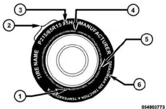
1 — U.S. DOT Safety Standards
Code (TIN)
2 — Size Designation
3 — Service Description
4 — Maximum Load
5 — Maximum Pressure
6 — Treadwear, Traction and
Temperature Grades
NOTE:
- P (Passenger) — Metric tire sizing is based on U.S. design standards. P-Metric tires have the letter "P" molded into the sidewall preceding the size designation. Example: P215/65R15 95H.
- European — Metric tire sizing is based on European design standards. Tires designed to this standard have the tire size molded into the sidewall beginning with the section width. The letter "P" is absent from this tire size designation. Example: 215/65R15 96H.
- LT (Light Truck) — Metric tire sizing is based on U.S. design standards. The size designation for LT-Metric tires is the same as for P-Metric tires except for the letters "LT" that are molded into the sidewall preceding the size designation. Example: LT235/85R16.
STARTING AND OPERATING 383
- Temporary spare tires are designed for temporary emergency use only. Temporary high pressure compact spare tires have the letter "T" or "S" molded into the sidewall preceding the size designation. Example: T145/80D18 103M.
- High flotation tire sizing is based on U.S. design standards and it begins with the tire diameter molded into the sidewall. Example: 31x10.5 R15 LT.
TireSizingChart
EXAMPLE:
ExampleSizeDesignation:P215/65R15XL95H,215/65R1596H,LT235/85R16C,T145/80D18103M,31x10.5R15LT
P= Passenger car tire size based on U.S. design standards, or "....blank....." = Passenger car tire based on European design standards, or LT= Light truck tire based on U.S. design standards, or T o r S = Temporary spare tire or 31= Overall diameter in inches (in) 215,235,145= Section width in millimeters (mm)
384 STARTING AND OPERATING
EXAMPLE:
| 65,85,80= Aspect ratio in percent (%)– Ratio of section height to section width of tire, or10.5= Section width in inches (in) |
| R= Construction code– "R"means radial construction, or– "D"means diagonal or bias construction |
| 15,16,18= Rim diameter in inches (in) |
| ServiceDescription: |
| 95= Load Index– A numerical code associated with the maximum load a tire can carry |
EXAMPLE:
H= Speed Symbol
– A symbol indicating the range of speeds at which a tire can carry a load corresponding to its load index under certain operating conditions
- The maximum speed corresponding to the speed symbol should only be achieved under specified operating conditions (i.e., tire pressure, vehicle loading, road conditions, and posted speed limits)
LoadIdentification:
Absence of the following load identification symbols on the sidewall of the tire indicates a Standard Load (SL) tire:
- XL=Extra load (or reinforced) tire, or
- LL=Light load tire or
- C, D, E, F, G = Load range associated with the maximum load a tire can carry at a specified pressure
MaximumLoad– Maximum load indicates the maximum load this tire is designed to carry
Maximum Pressure - Maximum pressure indicates the maximum permissible cold tire inflation pressure for this tire
386 STARTING AND OPERATING
Tire Identification Number (TIN)
The TIN may be found on one or both sides of the tire, however, the date code may only be on one side. Tires with white sidewalls will have the full TIN, including the date code, located on the white sidewall side of the tire.
Look for the TIN on the outboard side of black sidewall tires as mounted on the vehicle. If the TIN is not found on the outboard side, then you will find it on the inboard side of the tire.
| EXAMPLE: |
| DOTMAL9ABCD0301 |
| DOT= Department of Transportation- This symbol certifies that the tire is in compliance with the U.S. Department of Transportation tire safety standards and is approved for highway use |
| MA= Code representing the tire manufacturing location (two digits) |
| L9= Code representing the tire size (two digits) |
| ABCD= Code used by the tire manufacturer (one to four digits) |
| 03= Number representing the week in which the tire was manufactured (two digits)- 03 means the 3rd week |
| 01= Number representing the year in which the tire was manufactured (two digits) - 01 means the year 2001 - Prior to July 2000, tire manufacturers were only required to have one number to represent the year in which the tire was manufactured. Example: 031 could represent the 3rd week of 1981 or 1991 |
Tire Terminology And Definitions
| TermDefinition | |
| B-PillarThe vehicle B-Pillar | is the structural member of the body located behind the front door. |
| ColdTireInflationPressureCold tire in | flation pressure is defined as the tire pressure after the vehicle has not been driven for at least three hours, or driven less than 1 mile (1.6 km) after sitting for a minimum of three hours. Inflation pressure is measured in units of PSI (pounds per square inch) or kPa (kilopascals). |
388 STARTING AND OPERATING
| TermDefinition | |
| MaximumInflationPressureThe maximum inflation pressure is the maximum permissible cold tire inflation pressure for this tire. The maximum inflation pressure is molded into the sidewall. | |
| RecommendedColdTireInflation Pressure | Vehicle manufacturer's recommended cold tire inflation pressure as shown on the tire placard. |
| TirePlacardA label permanently attached to the vehicle describing the vehicle's loading capacity, the original equipment tire sizes and the recommended cold tire inflation pressures. | |
STARTING AND OPERATING 389
Tire Loading And Tire Pressure
TireAndLoadingInformationPlacardLocation
NOTE: The proper cold tire inflation pressure is listed on the driver's side B-Pillar or the rear edge of the driver's side door.

natural_image
Close-up of a car door handle with a black arrow pointing to a vertical panel, showing no text or symbols on the door itself.ExampleTirePlacardLocation(Door)
390 STARTING AND OPERATING

natural_image
Interior view of a car showing seat, door, and latch mechanism (no text or symbols)ExampleTirePlacardLocation(B-Pillar)
TireAndLoadingInformationPlacard

811b5a9a
TireAndLoadingInformationPlacard
This placard tells you important information about the:
- Number of people that can be carried in the vehicle.
-
Total weight your vehicle can carry.
-
Tire size designed for your vehicle.
- Cold tire inflation pressures for the front, rear, and spare tires.
Loading
The vehicle maximum load on the tire must not exceed the load carrying capacity of the tire on your vehicle. You will not exceed the tire's load carrying capacity if you adhere to the loading conditions, tire size, and cold tire inflation pressures specified on the Tire and Loading Information placard and in the "Vehicle Loading" section of this manual.
NOTE: Under a maximum loaded vehicle condition, gross axle weight ratings (GAWRs) for the front and rear axles must not be exceeded. For further information on GAWRs, vehicle loading, and trailer towing, refer to "Vehicle Loading" in this section.
To determine the maximum loading conditions of your vehicle, locate the statement "The combined weight of occupants and cargo should never exceed XXX lbs or XXX kg" on the Tire and Loading Information placard. The combined weight of occupants, cargo/luggage and trailer tongue weight (if applicable) should never exceed the weight referenced here.
StepsForDeterminingCorrectLoadLimit
- Locate the statement "The combined weight of occupants and cargo should never exceed XXX lbs or XXX kg" on your vehicle's placard.
- Determine the combined weight of the driver and passengers that will be riding in your vehicle.
- Subtract the combined weight of the driver and passengers from XXX lbs or XXX kg.
392 STARTING AND OPERATING
- The resulting figure equals the available amount of cargo and luggage load capacity. For example, if "XXX" amount equals 1,400 lbs (635 kg) and there will be five 150 lb (68 kg) passengers in your vehicle, the amount of available cargo and luggage load capacity is 650 lbs (295 kg) (since 5 x 150 lbs (68 kg) = 750 lbs (340 kg), and 1400 lbs (635 kg) - 750 lbs (340 kg) = 650 lbs [295 kg]).
- Determine the combined weight of luggage and cargo being loaded on the vehicle. That weight may not safely exceed the available cargo and luggage load capacity calculated in step 4.
NOTE:
- If your vehicle will be towing a trailer, load from your trailer will be transferred to your vehicle. The following table shows examples on how to calculate total load, cargo/luggage, and towing capacities of your vehicle with varying seating configurations and number and size of occupants. This table is for illustration purposes only and may not be accurate for the seating and load carry capacity of your vehicle.
- For the following example, the combined weight of occupants and cargo should never exceed 865 lbs (392 kg).

811a4d11
WARNING!
Overloading of your tires is dangerous. Overloading can cause it is a failure, affect vehicle handling, and increase your stopping distance. Usetires of the recommended load capacity for your vehicle. Never overload them.
TIRES — GENERAL INFORMATION
Tire Pressure
Proper tire inflation pressure is essential to the safe and satisfactory operation of your vehicle. Four primary areas are affected by improper tire pressure:
•Safety and Vehicle Stability
• Economy
•Tread Wear
- Ride Comfort
Safety
WARNING!
- Improperlyinflatedtiresaredangerousandcan causecollisions.
- Under-inflationincreasestireflexingandcanresultinoverheatingandtirefailure.
• Over-inflationreducesatire'sabilitytocushion shock.Objectsontheroadandchuckholescan causedamagethatresultintirefailure.
• Overinflatedorunder-inflatedtirescanaffective-vehiclehandlingandcanfailsuddenly,resulting in lossofvehiclecontrol. - Unequaltirepressurescancausesteeringproblems.Youcouldlosecontrolofyourvehicle.
(Continued)
WARNING!(Continued)
- Unequaltirepressuresfromonesideofthevehicle totheothercancausethevehicletodrifttothe rightorleft.
- Alwaysdrivewitheachtireinflatedtotherecommendedcoldtireinflationpressure.
Both under-inflation and over-inflation affect the stability of the vehicle and can produce a feeling of sluggish response or over responsiveness in the steering.
NOTE:
- Unequal tire pressures from side to side may cause erratic and unpredictable steering response.
- Unequal tire pressure from side to side may cause the vehicle to drift left or right.
Economy
Underinflated tires will increase tire rolling resistance resulting in higher fuel consumption.
RideComfortAndVehicleStability
Proper tire inflation contributes to a comfortable ride. Over-inflation produces a jarring and uncomfortable ride.
Tire Inflation Pressures
The proper cold tire inflation pressure is listed on the driver's side B-Pillar or rear edge of the driver's side door.
At least once a month:
- Check and adjust tire pressure with a good quality pocket-type pressure gauge. Do not make a visual judgement when determining proper inflation. Tires may look properly inflated even when they are under-inflated.
- Inspect tires for signs of tire wear or visible damage.
CAUTION!
Afterinspectingoradjustingthetirepressure,alwaysreinstallthevalvestemcap.Thiswillprevent moistureanddirtfromenteringthevalvestem, whichcoulddamagethevalvestem.
Inflation pressures specified on the placard are always "cold tire inflation pressure." Cold tire inflation pressure is defined as the tire pressure after the vehicle has not been driven for at least three hours, or driven less than 1 mile (1.6 km) after sitting for a minimum of three hours. The cold tire inflation pressure must not exceed the maximum inflation pressure molded into the tire sidewall.
Check tire pressures more often if subject to a wide range of outdoor temperatures, as tire pressures vary with temperature changes.
Tire pressures change by approximately 1 psi (7 kPa) per 12^ F ( 7^ C) of air temperature change. Keep this in mind when checking tire pressure inside a garage, especially in the winter.
Example: If garage temperature = 68^ F ( 20^ C) and the outside temperature = 32^ F ( 0^ C) then the cold tire inflation pressure should be increased by 3 psi (21 kPa), which equals 1 psi (7 kPa) for every 12^ F ( 7^ C) for this outside temperature condition.
Tire pressure may increase from 2 to 6 psi (13 to 40 kPa) during operation. DO NOT reduce this normal pressure build up or your tire pressure will be too low.
Tire Pressures For High Speed Operation
The manufacturer advocates driving at safe speeds and within posted speed limits. Where speed limits or conditions are such that the vehicle can be driven at high speeds, maintaining correct tire inflation pressure is very important. Increased tire pressure and reduced vehicle loading may be required for high-speed vehicle operation. Refer to your authorized tire dealer or original equipment vehicle dealer for recommended safe operating speeds, loading and cold tire inflation pressures.
WARNING!
Highspeeddrivingwithyourvehicleundermaximumloadisdangerous.Theaddedstrainonyour tirescouldcausethemtofail.Youcouldhavea seriouscollision.Donotdriveavehicleloadedtothe maximumcapacityatcontinuousspeedsabove 75mph(120km/h).
Tire Maintenance and Replacement
You should follow all maintenance procedures specified by the manufacturer of this vehicle's tires. The tires originally installed on this vehicle were designed to conform to EPA greenhouse gas standards and NHTSA fuel economy standards.
If you need to replace your tires, you should do so with tires that meet those standards. Check with your authorized dealer or with the tire manufacturer for appropriate replacement tires.
398 STARTING AND OPERATING
Radial Ply Tires
WARNING!
Combiningradialplytireswithothertypesoftires onyourvehiclewillcauseyourvehicletohandle poorly.Theinstabilitycouldcauseacollision.Alwaysuseradialplytiresinsetsoffour.Never combinethemwithothertypesoftires.
TireRepair
If your tire becomes damaged, it may be repaired if it meets the following criteria:
• The tire has not been driven on when flat.
- The damage is only on the tread section of your tire (sidewall damage is not repairable).
- The puncture is no greater than a 14 of an inch (6 mm).
Consult an authorized tire dealer for tire repairs and additional information.
Damaged Run Flat tires, or Run Flat tires that have experienced a loss of pressure should be replaced immediately with another Run Flat tire of identical size and service description (Load Index and Speed Symbol).
Tire Types
AllSeasonTires—IfEquipped
All Season tires provide traction for all seasons (spring, summer, fall and winter). Traction levels may vary between different all season tires. All season tires can be identified by the M+S, M&S, M/S or MS designation on the tire sidewall. Use all season tires only in sets of four; failure to do so may adversely affect the safety and handling of your vehicle.
SummerOrThreeSeasonTires—IfEquipped
Summer tires provide traction in both wet and dry conditions, and are not intended to be driven in snow or on ice. If your vehicle is equipped with summer tires, be aware these tires are not designed for winter or cold driving conditions. Install winter tires on your vehicle when ambient temperatures are less than 40^ F ( 5^ C) or if roads are covered with ice or snow. For more information, contact an authorized dealer.
Summer tires do not contain the all season designation or mountain/snowflake symbol on the tire sidewall. Use summer tires only in sets of four; failure to do so may adversely affect the safety and handling of your vehicle.
WARNING!
Donotusesummertiresinsnow/iceconditions. You could lose vehicle control, resulting in severe injury or death. Driving to fast for conditions also creates the possibility of loss of vehicle control.
SnowTires
Some areas of the country require the use of snow tires during the winter. Snow tires can be identified by a "mountain/snowflake" symbol on the tire sidewall.

If you need snow tires, select tires equivalent in size and type to the original equipment tires. Use snow tires only in sets of four; failure to do so may adversely affect the safety and handling of your vehicle.
400 STARTING AND OPERATING
Snow tires generally have lower speed ratings than what was originally equipped with your vehicle and should not be operated at sustained speeds over 75 mph (120 km/h). For speeds above 75 mph (120 km/h) refer to original equipment or an authorized tire dealer for recommended safe operating speeds, loading and cold tire inflation pressures.
While studded tires improve performance on ice, skid and traction capability on wet or dry surfaces may be poorer than that of non-studded tires. Some states prohibit studded tires; therefore, local laws should be checked before using these tire types.
Run Flat Tires — If Equipped
Run Flat tires allow you the capability to drive 50 miles (80 km) at 50 mph (80 km/h) after a rapid loss of inflation pressure. This rapid loss of inflation is referred to as the Run Flat mode. A Run Flat mode occurs when the tire inflation pressure is of/or below 14 psi (96 kPa). Once a Run Flat tire reaches the run flat mode it has limited driving capabilities and needs to be replaced immediately. A Run Flat tire is not repairable.
It is not recommended driving a vehicle loaded at full capacity or to tow a trailer while a tire is in the run flat mode.
See the tire pressure monitoring section for more information.
Spare Tires — If Equipped
NOTE: For vehicles equipped with Tire Service Kit instead of a spare tire, please refer to "Tire Service Kit" in "What To Do In Emergencies" for further information.
CAUTION!
Because of the reduced ground clearance, donottake your vehicle through an automatic car wash with a compactor limited - usetemporary spare installed. Damageto the vehicle may result.
SpareTireMatchingOriginalEquippedTireAndWheel—IfEquipped
Your vehicle may be equipped with a spare tire and wheel equivalent in look and function to the original equipment tire and wheel found on the front or rear axle of your vehicle. This spare tire may be used in the tire rotation for your vehicle. If your vehicle has this option, refer to an authorized tire dealer for the recommended tire rotation pattern.
CompactSpareTire—IfEquipped
The compact spare is for temporary emergency use only. You can identify if your vehicle is equipped with a compact spare by looking at the spare tire description on the Tire and Loading Information Placard located on the driver's side door opening or on the sidewall of the tire. Compact spare tire descriptions begin with the letter "T" or "S" preceding the size designation. Example: T145/80D18 103M.
T, S = Temporary Spare Tire
Since this tire has limited tread life, the original equipment tire should be repaired (or replaced) and reinstalled on your vehicle at the first opportunity.
Do not install a wheel cover or attempt to mount a conventional tire on the compact spare wheel, since the wheel is designed specifically for the compact spare tire.
402 STARTING AND OPERATING
Do not install more than one compact spare tire and wheel on the vehicle at any given time.
WARNING!
Compactsparesarefortemporaryemergencyuse only.Withthesespares,donotdrivemorethan 50mph(80km/h).Temporaryusespareshavelimited treadlife.Whenthetreadisworntothetreadwear indicators,thetemporaryusesparetireneedstobe replaced.Besuretofollowthewarnings,which applytoyourspare.Failureretodosocouldresultin sparetirefailureandlossofvehiclecontrol.
FullSizeSpare—IfEquipped
The full size spare is for temporary emergency use only. This tire may look like the originally equipped tire on the front or rear axle of your vehicle, but it is not. This spare tire may have limited tread life. When the tread is worn
to the tread wear indicators, the temporary use full size spare tire needs to be replaced. Since it is not the same as your original equipment tire, replace (or repair) the original equipment tire and reinstall on the vehicle at the first opportunity.
Limited-UseSpare—IfEquipped
The limited-use spare tire is for temporary emergency use only. This tire is identified by a label located on the limited-use spare wheel. This label contains the driving limitations for this spare. This tire may look like the original equipped tire on the front or rear axle of your vehicle, but it is not. Installation of this limited-use spare tire affects vehicle handling. Since it is not the same as your original equipment tire, replace (or repair) the original equipment tire and reinstall on the vehicle at the first opportunity.
WARNING!
Limited-usesparesareforemergencyuseonly.Installationofthislimited-usesparetireaffectsvehicle handling.Withthistire,donotdrivemorethanthe speedlistedonthelimit-usesparewheel.Keep inflatedtothecoldtireinflationpressureslistedon yourTireandLoadingInformationPlacardlocated onthedriver'ssideB-Pillarortherearedgeofthe driver'ssidedoor.Replace(orrepair)theoriginal equipmenttireatthefirstopportunityandreinstallit onyourvehicle.Failureretodosocouldresultinloss ofvehiclecontrol.
Tire Spinning
When stuck in mud, sand, snow, or ice conditions, do not spin your vehicle's wheels above 30 mph (48 km/h) or for longer than 30 seconds continuously without stopping.
Refer to "Freeing A Stuck Vehicle" in "What To Do In Emergencies" for further information.
WARNING!
Fastspinningtirescanbedangerous. Forces generated by excessive wheel speeds may cause it damaged or failure. Atire could explode and injures someone. Donotspinyour vehicle's wheels faster than 30 mph (48 km/h) form more than 30 seconds continuously when you are stuck, and donotlet any on near aspinning wheel, no matter what the speed.
Tread Wear Indicators
Tread wear indicators are in the original equipment tires to help you in determining when your tires should be replaced.
natural_image
Close-up of two car tires showing tread pattern and tire tread (no text or symbols)055007576
1 — Worn Tire 2 — New Tire
These indicators are molded into the bottom of the tread grooves. They will appear as bands when the tread depth becomes a 1/16 of an inch (2 mm). When the tread is
worn to the tread wear indicators, the tire should be replaced. Refer to "Replacement Tires" in this section for further information.
Life Of Tire
The service life of a tire is dependent upon varying factors including, but not limited to:
- Driving style.
- Tire pressure - Improper cold tire inflation pressures can cause uneven wear patterns to develop across the tire tread. These abnormal wear patterns will reduce tread life, resulting in the need for earlier tire replacement.
- Distance driven.
- Performance tires, tires with a speed rating of V or higher, and summer tires typically have a reduced tread life. Rotation of these tires per the vehicle maintenance schedule is highly recommended.
WARNING!
Tiresandthesparetireshouldbereplacedaftersix years, regardless of the remaining tread. Failure to follow this warning can result in sudden tire failure. You could lose control and have a collision resulting in serious injury or death.
Keep dismounted tires in a cool, dry place with as little exposure to light as possible. Protect tires from contact with oil, grease, and gasoline.
Replacement Tires
The tires on your new vehicle provide a balance of many characteristics. They should be inspected regularly for wear and correct cold tire inflation pressures. The manufacturer strongly recommends that you use tires equivalent to the originals in size, quality and performance when replacement is needed. Refer to the paragraph on "Tread Wear Indicator." Refer to the Tire and Loading
Information placard or the Vehicle Certification Label for the size designation of your tire. The Load Index and Speed Symbol for your tire will be found on the original equipment tire sidewall. See the Tire Sizing Chart example found in the Tire Safety Information section of this manual for more information relating to the Load Index and Speed Symbol of a tire.
It is recommended to replace the two front tires or two rear tires as a pair. Replacing just one tire can seriously affect your vehicle's handling. If you ever replace a wheel, make sure that the wheel's specifications match those of the original wheels.
It is recommended you contact your authorized tire dealer or original equipment dealer with any questions you may have on tire specifications or capability. Failure to use equivalent replacement tires may adversely affect the safety, handling, and ride of your vehicle.
WARNING!
- Donotuseatire, wheelsizeorratingotherthan thatspecifiedforyourvehicle. Some combinations of unapprovedtiresandwheelsmaychangesuspensiondimensionsandperformancecharacteristics, resultinginchangestosteering, handling, and brakingofyourvehicle. This can cause unpredictablehandlingandstresstosteeringandsuspensioncomponents. You could lose control and have a collision resulting in serious injury or death. Use only the tire and wheelsizes with load ratings approved for your vehicle.
- Neveruseatirewithasmallerloadindexor capacity,otherthanwhatwasoriginallyequipped onyourvehicle.Usingatirewithasmallerload indexcouldresultintireoverloadingandfailure. Youcouldlosecontrolandhaveacollision.
WARNING!(Continued)
- Failuretoequipyourvehiclewithtireshaving adequatespeedcapabilitycanresultinsuddentire failureandlossofvehiclecontrol.
CAUTION!
Replacingoriginaltireswithtiresofadifferentsize mayresultinfalsespeedometerandodometerreadings.
SUPPLEMENTAL TIRE PRESSURE INFORMATION — IF EQUIPPED
A light load vehicle condition is defined as two passengers [150 lbs (68 kg) each] plus 200 lbs (91 kg) of cargo. Cold tire inflation pressures for a lightly loaded vehicle will be found on the face of the driver's door.
TIRE CHAINS (TRACTION DEVICES)
Use of traction devices require sufficient tire-to-body clearance. Follow these recommendations to guard against damage.
Please follow the table below for proper tire size, chain type, and axle recommendations:
- Traction device must be of proper size for the tire, as recommended by the traction device manufacturer.
| VehicleAxleRecommendationsTireSizesChainClass | |||
| Chassis Cab 3500 (Single Rear Wheel) Models | Rear Only LT265/70 | R18E U Class | |
| Chassis Cab 3500 (Dual Rear Wheel) 4X2 Models | Rear Only LT235/80 | R17E U Class | |
| Chassis Cab 3500 (Dual Rear Wheel) 4X4 Models | Front/Rear LT235/80 | R17E U Class | |
| Chassis Cab 4500/5500 Models | Rear Only 225/70R | 19.5G U Class | |
WARNING!
Using tires of different size and type (M+S, Snow) between front and rear axles can cause unpredictable handling. You could close control and have a collision.
CAUTION!
To avoid damagetoyourvehicleortires, observethe following precautions:
- Because of restricted traction device clearance between tires and others suspension components, it is important that only traction devices being good condition are used. Brokendevices can cause serious damage. Stop the vehicle immediately if noise occurs that could indicate device breakage. Remove the damaged part of the device before further use.
CAUTION!(Continued)
- Installdeviceastightlyaspossibleandthenre-tightenafterdrivingabout ^1/2 mile(0.8km).
- Donotexceed30mph(48km/h).
- Drivecautiously and avoid severeturnsandlarge bumps, especially withloaded vehicle.
- Donotdriveforaprolongedperiodondrypavement.
- Observethetractiondevicemanufacturer'sinstructionsonthemethodofinstallation,operating speed,andconditionsforuse.Alwaysusethe suggestedoperatingspeedofthedevicemanufac-turer'sifitislessthan30mph(48km/h).
- Donotusetractiondevicesonacompactsparetire.
TIRE ROTATION RECOMMENDATIONS
Tires on the front and rear axles of vehicles operate at different loads and perform different steering, driving, and braking functions. For these reasons, they wear at unequal rates.
These effects can be reduced by timely rotation of tires. The benefits of rotation are especially worthwhile with aggressive tread designs such as those on On/Off Road type tires. Rotation will increase tread life, help to maintain mud, snow, and wet traction levels, and contribute to a smooth, quiet ride.
Refer to the "Maintenance Schedule" for the proper maintenance intervals. More frequent rotation is permissible if desired. The reasons for any rapid or unusual wear should be corrected prior to rotation being performed.

flowchart
graph TD
    A["Vehicle"] --> B[" collision"]
    C["Vehicle"] --> B
    D["Vehicle"] --> B
    B --> E[" collision"]
    style A fill:#f9f,stroke:#333
    style C fill:#f9f,stroke:#333
    style D fill:#f9f,stroke:#333
    style E fill:#ccf,stroke:#333
055703771
TireRotation
NOTE: On Canadian vehicles only, if your vehicle is equipped with All-Season type tires on the front and On/Off Road type tires mounted on the rear, do not use a front to back rotation pattern. Instead, rotate your tires side to side at the recommended intervals.
410 STARTING AND OPERATING
Dual Rear Wheels

The tires used on dual wheel assemblies should be matched for wear to prevent overloading one tire in a set. To check if tires are even, lay a straight edge across all four tires. The straight edge should touch all the tires.
NOTE: If your vehicle is equipped with a Tire Pressure Information System (TPIS):
- The Tire Pressure Information System (TPIS) uses unique sensors in the inner rear wheels to help identify them from the outer rear wheels, because of this, the inner and outer wheel locations can't be switched.
- After a tire rotation is completed, as shown below, the system can auto learn the locations of each sensor ID. Auto learning/localization occurs when the vehicle ignition status is changed from Off to On and speeds of greater than 5 mph (8km/h) are obtained and remain over 5mph (8km/h) for at about a 15 minute period. You may need to drive for 20 minutes to account slower speeds and stops.
- If the tires are rotated incorrectly, The Auto localization of the TPIS sensors will fail to locate correctly resulting in incorrect locations for the pressure values displayed in the Instrument Cluster.
CAUTION!
4500/5500DualRearTiresmayonlyhaveoneapproveddirectionofrotation. Thisistoaccommodate theasymmetricaldesign(treadpattern)oftheOn/Off roadtire.
- Whenreplacingaflat,thesparetiremayhavetobe remountedontherimorinstalledatadifferent locationtomaintainthecorrectplacementofthe tireonthewheelrelativetothetire/wheelposition onthevehicle.Forexample,ifthespareisusedto replaceanouterreartireitwillhavetobere-mountedontherimsothatthewwheelisdished inward.Thatwaythetreaddesignofasymmetrical tireswillmaintainproperposition.
TIRE PRESSURE MONITOR SYSTEM (TPMS)
The Tire Pressure Monitor System (TPMS) will warn the driver of a low tire pressure based on the vehicle recommended cold placard pressure.
The tire pressure will vary with temperature by about 1 psi (7 kPa) for every 12°F (6.5°C). This means that when the outside temperature decreases, the tire pressure will decrease. Tire pressure should always be set based on cold inflation tire pressure. This is defined as the tire pressure after the vehicle has not been driven for at least three hours, or driven less than 1 mile (1.6 km) after a three hour period. The cold tire inflation pressure must not exceed the maximum inflation pressure molded into the tire sidewall. Refer to “Tires – General Information” in “Starting and Operating” for information on how to properly inflate the vehicle’s tires. The tire pressure will also increase as the vehicle is driven - this is normal and there should be no adjustment for this increased pressure.
412 STARTING AND OPERATING
The TPMS will warn the driver of a low tire pressure if the tire pressure falls below the low-pressure warning limit for any reason, including low temperature effects and natural pressure loss through the tire.
The TPMS will continue to warn the driver of low tire pressure as long as the condition exists, and will not turn off until the tire pressure is at or above the recommended cold placard pressure. Once the low tire pressure warning (Tire Pressure Monitoring [TPM] Telltale Light) illuminates, you must increase the tire pressure to the recommended cold placard pressure in order for the “Tire Pressure Monitoring Telltale Light” to turn off. The system will automatically update and the “Tire Pressure Monitoring Telltale Light” will turn off once the system receives the updated tire pressures. The vehicle may need to be driven for up to 20 minutes above 15 mph (25 km/h) in order for the TPMS to receive this information.
For example, your vehicle may have a recommended cold (parked for more than three hours) placard pressure of 30 psi (207 kPa). If the ambient temperature is 68°F (20°C) and the measured tire pressure is 27 psi (186 kPa), a temperature drop to 20°F (-7°C) will decrease the tire pressure to approximately 23 psi (158 kPa). This tire pressure is sufficiently low enough to turn ON the “Tire Pressure Monitoring Telltale Light.” Driving the vehicle may cause the tire pressure to rise to approximately 27 psi (186 kPa), but the “Tire Pressure Monitoring Telltale Light” will still be ON. In this situation, the “Tire Pressure Monitoring Telltale Light” will turn OFF only after the tires are inflated to the vehicle’s recommended cold placard pressure value.
CAUTION!
- TheTPMShasbeenoptimizedfortheoriginal equipmenttiresandwheels.TPMSpressureshave beenestablishedforthetiresizeequippedonyour vehicle.Undesirablesystemoperationorsensor damagemayresultwhenusingreplacementequipmentthatisnotofthesamesize,type,and/orstyle. Aftermarketwheelscancausesensordamage.UsingaftermarkettiresealantsmaycausetheTire PressureMonitoringSystem(TPMS)sensortobecomeinoperable.Afterusinganaftermarkettire sealantitisrecommendedthatyoutakeyour vehicletoanauthorizeddealershiptohaveyour sensorfunctionchecked.
- Afterinspectingoradjustingthetirepressurealwaysreinstallthevalvestemcap.Thiswillprevent moistureanddirtfromenteringthevalvestem, whichcoulddamagetheTPMSsensor.
NOTE:
- The TPMS is not intended to replace normal tire care and maintenance or to provide warning of a tire failure or condition.
- The TPMS should not be used as a tire pressure gauge while adjusting your tire pressure.
- Driving on a significantly under-inflated tire causes the tire to overheat and can lead to tire failure. Under-inflation also reduces fuel efficiency and tire tread life, and may affect the vehicle's handling and stopping ability.
- The TPMS is not a substitute for proper tire maintenance, and it is the driver's responsibility to maintain correct tire pressure using an accurate tire pressure gauge, even if under-inflation has not reached the level to trigger illumination of the "Tire Pressure Monitoring Telltale Light."
414 STARTING AND OPERATING
- Seasonal temperature changes will affect tire pressure, and the TPMS will monitor the actual tire pressure in the tire.
Base System — If Equipped
The Tire Pressure Monitor System (TPMS) uses wireless technology with wheel rim mounted electronic sensors to monitor tire pressure levels. Sensors mounted to each wheel as part of the valve stem transmit tire pressure readings to the receiver module.
NOTE: It is particularly important for you to check the tire pressure in all of the tires on your vehicle monthly and to maintain the proper pressure.
The TPMS consists of the following components:
- Receiver module,
- Four TPM sensors, and
- TPM Telltale Light
The matching full size spare wheel and tire assembly (if equipped) has a TPM sensor. The matching full size spare can be used in place of any of the four road tires. The TPMS will only monitor the pressure in the full size spare when it is used in place of a road tire. Otherwise, a spare with a pressure below the low-pressure limit will not cause the “Tire Pressure Monitoring Telltale Light” to illuminate or the chime to sound.
Premium System
The Tire Pressure Monitor System (TPMS) uses wireless technology with wheel rim mounted electronic sensors to monitor tire pressure levels. Sensors mounted to each wheel as part of the valve stem transmit tire pressure readings to the receiver module.
NOTE: It is particularly important for you to check the tire pressure in all of the tires on your vehicle monthly and to maintain the proper pressure.
The TPMS consists of the following components:
- Receiver module
- Four TPM sensors
- Various TPMS messages, which display in the Electronic Vehicle Information Center (EVIC)/Driver Information Display (DID)
- TPM Telltale Light
The matching full size spare wheel and tire assembly (if equipped) has a TPM sensor. The full size spare can be used in place of any of the four road tires. A spare with a pressure below the low-pressure limit will not cause the "Tire Pressure Monitoring Telltale Light" to illuminate or the chime to sound while it is stored in the spare tire location.
TirePressureMonitoringLowPressureWarnings
The "Tire Pressure Monitoring Telltale Light" will illuminate in the instrument cluster and a chime will sound when tire pressure is low in one or more of the four active road tires. In addition, the EVIC/DID will display a "LOW TIRE" message and a graphic showing the pressure values of each tire with the low tire pressure values in a different color. An "Inflate to XX" message will also be displayed.
EXAMPLE ONLY

"LOWTIREPRESSURE"Message
Should this occur, you should stop as soon as possible and inflate the tires with a low pressure condition (those in a different color in the EVIC/DID graphic) to the vehicle's recommended cold placard pressure inflation value as shown in the "Inflate to XX" message. Once the system receives the updated tire pressures, the system
will automatically update, the graphic display in the EVIC/DID will return to its original color, and the "Tire Pressure Monitoring Telltale Light" will turn off. The vehicle may need to be driven for up to 20 minutes above 15 mph (24 km/h) in order for the TPMS to receive this information.
ServiceTPMSWarning
If a system fault is detected, the "Tire Pressure Monitoring Telltale Light" will flash on and off for 75 seconds and then remain on solid. The system fault will also sound a chime. In addition, the EVIC/DID will display a "SERVICE TPM SYSTEM" message for a minimum of five seconds and then display dashes (- -) in place of the pressure value to indicate which sensor is not being received.
STARTING AND OPERATING 417
EXAMPLE ONLY

055900260
TirePressureMonitorDisplay
If the ignition switch is cycled, this sequence will repeat, providing the system fault still exists. If the system fault no longer exists, the "Tire Pressure Monitoring Telltale Light" will no longer flash, and the "SERVICE TPM
SYSTEM" message will no longer display, and a pressure value will display in place of the dashes. A system fault can occur due to any of the following:
- Signal interference due to electronic devices or driving next to facilities emitting the same radio frequencies as the TPM sensors.
•Installing aftermarket window tinting that contains materials that may block radio wave signals.
• Accumulation of snow or ice around the wheels or wheel housings.
• Using tire chains on the vehicle. - Using wheels/tires not equipped with TPM sensors.
418 STARTING AND OPERATING
VehiclesWithMatchingFullSizeSpare
- The matching full size spare wheel and tire assembly has a TPM sensor that can be monitored by the TPMS.
- If you install the full size spare in place of a road tire that has a pressure below the low-pressure warning limit, upon the next ignition switch cycle, a chime will sound and the "Tire Pressure Monitoring Telltale Light" will turn ON. In addition, the EVIC/DID will display a "LOW TIRE" message and a graphic showing the low tire pressure value in a different color. An "Inflate to XX" message will also be displayed.
- After driving the vehicle for up to 20 minutes above 15 mph (25 km/h) the “Tire Pressure Monitoring Telltale Light” will turn OFF and the pressure value will be updated and return to it’s original color, as long as no tire pressure is below the low-pressure warning limit in any of the four active road tires.
VehiclesWithNonMatchingFullSizeSpare
- The compact spare tire does not have a TPM sensor. Therefore, the TPMS will not monitor the pressure in the compact spare tire.
- If you install the compact spare tire in place of a road tire that has a pressure below the low-pressure warning limit, upon the next ignition switch cycle, the TPM Telltale Light and a "LOW TIRE" message will remain ON and a chime will sound. In addition, the graphic in the EVIC/DID will still display a flashing pressure value or a pressure value in a different color.
-
After driving the vehicle for up to 20 minutes above 15 mph (24 km/h), the TPM Telltale Light will flash on and off for 75 seconds and then remain on solid. In addition, the EVIC/DID will display a "SERVICE TPM SYSTEM" message for a minimum of five seconds and then display dashes (- -) in place of the pressure value.
-
For each subsequent ignition switch cycle, a chime will sound, the TPM Telltale Light will flash on and off for 75 seconds and then remain on solid, and the EVIC/DID will display a "SERVICE TPM SYSTEM" message for a minimum of five seconds and then display dashes (- -) in place of the pressure value.
- Once you repair or replace the original road tire and reinstall it on the vehicle in place of the compact spare, the TPMS will update automatically. In addition, the TPM Telltale Light will turn OFF and the graphic in the EVIC/DID will display a new pressure value instead of dashes (- -), as long as no tire pressure is below the low-pressure warning limit in any of the four active road tires. The vehicle may need to be driven for up to 20 minutes above 15 mph (24 km/h) in order for the TPMS to receive this information.
Tire Pressure Information System (TPIS) Chassis Cab — If Equipped
Your vehicle may be equipped with a Tire Pressure Information System (TPIS).
The Tire Pressure Information System (TPIS) uses wireless technology with wheel rim mounted electronic sensors to transmit tire pressure levels. Sensors mounted to each wheel as part of the valve stem transmit tire pressure readings to the receiver module.
NOTE: It is particularly important for you to check the tire pressure in all of the tires on your vehicle monthly and to maintain the proper pressure.
The TPIS consists of the following components:
- Receiver module
- Four TPM sensors (Single Rear Wheel [SRW] applications)
420 STARTING AND OPERATING
- Six TPM sensors (Dual Rear Wheel [DRW] applications)
- Pressure display in the Electronic Vehicle Information Center (EVIC)/Driver Information Display (DID)
The TPIS system will display all four (Single Rear Wheel [SRW] applications) or six (Dual Rear Wheel [DRW] applications) tire pressure values EVIC/DID display.
If a system fault is detected, the EVIC/DID will display a "SERVICE TPM SYSTEM" message for a minimum of five seconds and then display dashes (--) in place of the pressure value to indicate which sensor is not being received.
If the ignition switch is cycled, this sequence will repeat, providing the system fault still exists. If the system fault no longer exists, the "SERVICE TPM SYSTEM" message will no longer be displayed, and a pressure value will display in place of the dashes. A system fault can occur due to any of the following:
- Signal interference due to electronic devices or driving next to facilities emitting the same radio frequencies as the TPM sensors.
- Installing aftermarket window tinting that contains materials that may block radio wave signals.
- Accumulation of snow or ice around the wheels or wheel housings.
• Using tire chains on the vehicle. - Using wheels/tires not equipped with TPM sensors.
General Information
This device complies with Part 15 of the FCC rules and RSS 210 of Industry Canada. Operation is subject to the following conditions:
- This device may not cause harmful interference.
- This device must accept any interference received, including interference that may cause undesired operation.
The TPM sensors are regulated under one of the following licenses:
| United States GQ4-61T | |
| Canada 1470A-42T |
FUEL REQUIREMENTS
5.7L/6.4L Engines

This engine is designed to meet all emissions regulations and provide satisfactory fuel economy and performance when using high quality unleaded gasoline having an octane range of 87 to 89. The manufac-
turer recommends the use of 89 octane for optimum performance. The use of premium gasoline (Over 89 octane) is not recommended, as it will not provide any benefit over regular gasoline in these engines.
Light spark knock at low engine speeds is not harmful to your engine. However, continued heavy spark knock at high speeds can cause damage and immediate service is required. Poor quality gasoline can cause problems such
422 STARTING AND OPERATING
as hard starting, stalling, and hesitations. If you experience these symptoms, try another brand of gasoline before considering service for the vehicle.
Over 40 auto manufacturer's world wide have issued and endorsed consistent gasoline specifications (the Worldwide Fuel Charter, WWFC) which define fuel properties necessary to deliver enhanced emissions, performance, and durability for your vehicle. The manufacturer recommends the use of gasolines that meet the WWFC specifications, if they are available.
Reformulated Gasoline
Many areas of the country require the use of cleaner burning gasoline referred to as “Reformulated Gasoline.” Reformulated gasoline contain oxygenates and are specifically blended to reduce vehicle emissions and improve air quality.
The manufacturer supports the use of reformulated gasoline. Properly blended reformulated gasoline will provide excellent performance and durability of engine and fuel system components.
Gasoline/Oxygenate Blends
Some fuel suppliers blend unleaded gasoline with oxygenates such as Ethanol.
CAUTION!
DONOTusegasolinecontainingMethanolorgasolinecontainingmorethan10%Ethanol.Useofthese blendsmayresultinstartinganddrivabilityproblems,damagecriticalfuelsystemcomponents,cause emissionstoexceedtheapplicablestandard,and/or causethe"MalfunctionIndicatorLight"toilluminate.Pumplabelsshouldclearlycommunicateifa fuelcontainsgreaterthan10%Ethanol.
Problems that result from using gasoline containing Methanol or gasoline containing more than 10% Ethanol are not the responsibility of the manufacturer and may not be covered under New Vehicle Limited Warranty.
E-85 Usage In Non-Flex Fuel Vehicles
Non-Flex Fuel Vehicles (FFV) are compatible with gasoline containing 10% ethanol (E10). Gasoline with higher ethanol content may void the New Vehicle Limited Warranty.
If a Non-FFV vehicle is inadvertently fueled with E-85 fuel, the engine will have some or all of these symptoms:
- Operate in a lean mode.
- OBD II "Malfunction Indicator Light" on.
- Poor engine performance.
- Poor cold start and cold drivability.
- Increased risk for fuel system component corrosion.
To fix a Non-FFV vehicle inadvertently fueled once with E-85 perform the following:
- Drain the fuel tank (see your authorized dealer).
- Change the engine oil and oil filter.
- Disconnect and reconnect the battery to reset the engine controller memory.
More extensive repairs will be required for prolonged exposure to E-85 fuel.
MMT In Gasoline
Methylcyclopentadienyl Manganese Tricarbonyl (MMT) is a manganese-containing metallic additive that is blended into some gasoline to increase octane. Gasoline blended with MMT provides no performance advantage beyond gasoline of the same octane number without MMT. Gasoline blended with MMT reduces spark plug life and reduces emissions system performance in some vehicles. The manufacturer recommends that gasoline
424 STARTING AND OPERATING
without MMT be used in your vehicle. The MMT content of gasoline may not be indicated on the gasoline pump, therefore, you should ask your gasoline retailer whether the gasoline contains MMT. MMT is prohibited in Federal and California reformulated gasoline.
Materials Added To Fuel
All gasoline sold in the United States is required to contain effective detergent additives. Use of additional detergents or other additives is not needed under normal conditions and they would result in additional cost. Therefore, you should not have to add anything to the fuel.
Fuel System Cautions
CAUTION!
Followtheseguidelinestomaintainyourvehicle's performance:
- The useofleadedgasisprohibitedbyFederallaw. Using leadedgasolinecanimpairengineperformanceanddamagetheemissionscontrolsystem.
- Anout-of-tuneengineorcertainfuelorignition malfunctionscancausethecatalyticconverterto overheat. If you notice apungentburningodor or somelightsmoke, you'renginemaybeoutoftune ormalfunctioning and may require immediateservice. Contact your authorized dealer for service assistance.
(Continued)
CAUTION!(Continued)
- Theuseoffueladditives, which are now being sold as octaneenhancers, is not recommended. Most of these products contain high concentrations of methanol. Fuelsystemdamage or vehicle performance problems resulting from the use of such fuel soradditives is not the responsibility of the manufacturer.
NOTE: Intentional tampering with the emissions control system can result in civil penalties being assessed against you.
Carbon Monoxide Warnings
WARNING!
Carbonmonoxide(CO)inexhaustgasesisdeadly. Followtheprecautionsbelowtopreventcarbon monoxidepoisoning:
- Donotinhaleexhaustgases. They contain carbon monoxide, acolorless and odorless gas, which can kill. Never run the engine in a closed area, such as agarage, and never sit in a parked vehicle with the engineer running for an extended period. If the vehicle is stopped in an open area with the engine running form more than a short period, adjust the ventilation system to force fresh, outside air into the vehicle.
(Continued)
426 STARTING AND OPERATING
WARNING!(Continued)
- Guardagainstcarbonmonoxidewithpropermaintenance.Havetheexhaustsysteminspectedevery timethevehicleisraised.Haveanyabnormal conditionsrepairedpromptly.Untilrepaired,drive withallsidewindowsfullyopen.
ADDING FUEL
CAUTION!
- Damagetothefuelsystemoremissionscontrol systemcouldresultfromusinganimproperfuel tankfillertubecap(fuelfillercap).Apoorlyfitting capcouldletimpuritiesintothefuelsystem.Also, apoorly-fittedaftermarketcapcancausetheMIL (MalfunctionIndicatorLight)toilluminatedueto fuelvaporsescapingfromthesystem.
CAUTION!(Continued)
- ApoorlyfittingfuelfillercapmaycausetheMILto turnon.
- Toavoidfuelspillageandoverfilling, donot"top off"thefueltankafterfilling.
NOTE: When the fuel nozzle "clicks" or shuts off the fuel tank is full.
WARNING!
- Neverhaveanysmokingmaterialslitinornearthe vehiclewhenthegascapisremovedorthetankis beingfilled.
- Neveraddfueltothevehiclewhentheengineis running. This is inviolation of most state and federal fireregulations and may cause the MIL to turn on.
(Continued)
NOTE: Tighten the gas cap 14 turn until you hear one click. This is an indication that the cap is properly tightened.
If the gas cap is not tightened properly, the Malfunction Indicator Light will come on. Be sure the gas cap is tightened every time the vehicle is refueled.
WARNING!
Afiremayresultifgasolineispumpedintoa portablecontainerthatisinsideofavehicle.You couldbeburned.Alwaysplacegascontainersonthe groundwhilefilling.
Loose Fuel Filler Cap Message

If the vehicle diagnostic system determines that the fuel filler cap is loose, improperly installed, or damaged, a loose gascap indicator
will display in the EVIC/DID telltale display area. Refer to "Electronic Vehicle Information Center (EVIC)/Driver Information Display (DID) in "Understanding Your Instrument Panel" for further information. Tighten the fuel filler cap properly and press the SELECT button to turn off the message. If the problem continues, the message will appear the next time the vehicle is started.
VEHICLE LOADING
Certification Label
As required by National Highway Traffic Safety Administration regulations, your vehicle has a certification label affixed to the driver's side door or pillar.
This label contains the month and year of manufacture, Gross Vehicle Weight Rating (GVWR), Gross Axle Weight Rating (GAWR) front and rear, and Vehicle Identification Number (VIN). A Month-Day-Hour (MDH) number is
428 STARTING AND OPERATING
included on this label and indicates the Month, Day and Hour of manufacture. The bar code that appears on the bottom of the label is your VIN.
GrossVehicleWeightRating(GVWR)
The GVWR is the total permissible weight of your vehicle including driver, passengers, vehicle, options and cargo. The label also specifies maximum capacities of front and rear axle systems (GAWR). Total load must be limited so GVWR and front and rear GAWR are not exceeded.
Payload
The payload of a vehicle is defined as the allowable load weight a truck can carry, including the weight of the driver, all passengers, options and cargo.
GrossAxleWeightRating(GAWR)
The GAWR is the maximum permissible load on the front and rear axles. The load must be distributed in the cargo area so that the GAWR of each axle is not exceeded. Each axle GAWR is determined by the components in the system with the lowest load carrying capacity (axle, springs, tires or wheels). Heavier axles or suspension components sometimes specified by purchasers for increased durability does not necessarily increase the vehicle's GVWR.
TireSize
The tire size on the Vehicle Certification Label represents the actual tire size on your vehicle. Replacement tires must be equal to the load capacity of this tire size.
RimSize
This is the rim size that is appropriate for the tire size listed.
InflationPressure
This is the cold tire inflation pressure for your vehicle for all loading conditions up to full GAWR.
CurbWeight
The curb weight of a vehicle is defined as the total weight of the vehicle with all fluids, including vehicle fuel, at full capacity conditions, and with no occupants or cargo loaded into the vehicle. The front and rear curb weight values are determined by weighing your vehicle on a commercial scale before any occupants or cargo are added.
Loading
The actual total weight and the weight of the front and rear of your vehicle at the ground can best be determined by weighing it when it is loaded and ready for operation.
The entire vehicle should first be weighed on a commercial scale to insure that the GVWR has not been exceeded. The weight on the front and rear of the vehicle should then be determined separately to be sure that the load is properly distributed over the front and rear axle. Weighing the vehicle may show that the GAWR of either the
front or rear axles has been exceeded but the total load is within the specified GVWR. If so, weight must be shifted from front to rear or rear to front as appropriate until the specified weight limitations are met. Store the heavier items down low and be sure that the weight is distributed equally. Stow all loose items securely before driving.
Improper weight distributions can have an adverse effect on the way your vehicle steers and handles and the way the brakes operate.
CAUTION!
DonotloadyourvehicleanyheavierthantheGVWR orthemaximumfrontandrearGAWR.Ifyoudo, partsonyourvehiclecanbreak,oritcanchangethe wayyourvehiclehandles.Thiscouldcauseyouto losecontrol.Alsooverloadingcanshortenthelifeof yourvehicle.
TRAILER TOWING
In this section you will find safety tips and information on limits to the type of towing you can reasonably do with your vehicle. Before towing a trailer, carefully review this information to tow your load as efficiently and safely as possible.
To maintain the New Vehicle Limited Warranty coverage, follow the requirements and recommendations in this manual concerning vehicles used for trailer towing.
Common Towing Definitions
The following trailer towing related definitions will assist you in understanding the following information:
GrossVehicleWeightRating(GVWR)
The GVWR is the total allowable weight of your vehicle. This includes driver, passengers, cargo and tongue weight. The total load must be limited so that you do not exceed the GVWR. Refer to "Vehicle Loading/Vehicle Certification Label" in "Starting and Operating" for further information.
GrossTrailerWeight(GTW)
The GTW is the weight of the trailer plus the weight of all cargo, consumables and equipment (permanent or temporary) loaded in or on the trailer in its "loaded and ready for operation" condition.
The recommended way to measure GTW is to put your fully loaded trailer on a vehicle scale. The entire weight of the trailer must be supported by the scale.
WARNING!
Ifthegrosstrailerweightis5,000lbs(2267kg)or more,itismandatorytouseaweight-distributing hitchtoensurestablehandlingofyourvehicle.If
(Continued)
WARNING!(Continued)
youuseastandardweight-carryinghitch,youcould losecontrolofyourvehicleandcauseacollision.
GrossCombinationWeightRating(GCWR)
The GCWR is the total permissible weight of your vehicle and trailer when weighed in combination.
GrossAxleWeightRating(GAWR)
The GAWR is the maximum capacity of the front and rear axles. Distribute the load over the front and rear axles evenly. Make sure that you do not exceed either front or rear GAWR. Refer to “Vehicle Loading/Vehicle Certification Label” in “Starting and Operating” for further information.
WARNING!
It is important that you donot exceed them maximum frontorrear GAWR. Adangerous driving condition can result if either rating is exceeded. You could lose control of the vehicle and have an accident.
TongueWeight(TW)
The tongue weight is the downward force exerted on the hitch ball by the trailer. The recommended tongue weight is 10% to 15% for a conventional hitch. You must consider this as part of the load on your vehicle.
FrontalArea
The frontal area is the maximum height multiplied by the maximum width of the front of a trailer.
TrailerSwayControl
The trailer sway control is a telescoping link that can be installed between the hitch receiver and the trailer tongue that typically provides adjustable friction associated with the telescoping motion to dampen any unwanted trailer swaying motions while traveling.
Weight-CarryingHitch
A weight-carrying hitch supports the trailer tongue weight, just as if it were luggage located at a hitch ball or some other connecting point of the truck. These kind of hitches are the most popular on the market today and they are commonly used to tow small- and medium-sized trailers.
Weight-DistributingHitch
A weight-distributing system works by applying leverage through spring (load) bars. They are typically used for heavier loads to distribute trailer tongue weight to the tow vehicle's front axle and the trailer axle(s). When used in accordance with the manufacturer's directions, it provides for a more level ride, offering more consistent steering and brake control, thereby enhancing towing safety. The addition of a friction/hydraulic sway control also dampens sway caused by traffic and crosswinds and contributes positively to tow vehicle and trailer stability. Trailer sway control and a weight distributing (load equalizing) hitch are recommended for heavier Tongue Weights (TW) and may be required depending on vehicle and trailer configuration/loading to comply with GAWR requirements.
WARNING!
- Animproperlyadjustedweightdistributinghitch systemmayreducehandling,stabilityandbraking performanceandcouldresultinacollision.
- Weightdistributingsystemsmaynotbecompatiblewithsurgebrakecouplers.Consultwithyour hitchandtrailermanufacturerorareputableRecreationalVehicledealerforadditionalinformation.

natural_image
Side-view illustration of a pickup truck pulling a small vehicle into a trailer (no text or symbols)0570049865
WithoutWeight-DistributingHitch(Incorrect)
434 STARTING AND OPERATING

natural_image
Side profile illustration of a pickup truck and a campfire vehicle (no text or symbols)0570049866

natural_image
Side profile illustration of a pickup truck with a trailer (no text or symbols)0570049867
WithWeight-DistributingHitch(Correct)ImproperAdjustmentOfWeight-DistributingHitch (Incorrect)
Fifth-WheelHitch
The fifth-wheel hitch is a special high platform with a coupling that mounts over the rear axle of the tow vehicle in the truck bed. It connects a vehicle and fifth-wheel trailer with a coupling king pin.
GooseneckHitch
The gooseneck hitch employs a pivoted coupling arm which attaches to a ball mounted in the bed of a pickup truck. The coupling arm connects to the hitch mounted over the rear axle in the truck bed.
Trailer Hitch Classification
The following chart provides the industry standard for the maximum trailer weight a given trailer hitch class can tow and should be used to assist you in selecting the correct trailer hitch for your intended towing condition.
| TrailerHitchClassificationDefinitions | |
| ClassMax.Trailer | HitchIndustryStandards |
| Class I - Light Duty 2,000 lbs (907 kg) | |
| Class II - Medium Duty 3,500 lbs (1 587 kg) | |
| TrailerHitchClassificationDefinitions | |
| Class III - Heavy Duty 5,000 lbs (2 268 kg) | |
| Class IV - Extra Heavy Duty | 10,000 lbs (4 540 kg) |
| Fifth Wheel/Gooseneck Greater than 10,000 lbs (4 540 kg) | |
| Refer to the “Trailer Towing Weights (Maximum Trailer Weight Ratings)” for the Maximum Gross Trailer Weight (GTW) towable for your given drivetrain. | |
| All trailer hitches should be professionally installed on your vehicle. | |
436 STARTING AND OPERATING
Trailer Towing Weights (Maximum Trailer Weight Ratings)
NOTE: For additional trailer towing information (maximum trailer weight ratings) refer to the following website addresses:
- ramtrucks.com/en/towing_guide/
- ramtruck.ca(Canada)
-rambodybuilder.com
Trailer And Tongue Weight
Always load a trailer with 60% of the weight in the front of the trailer. This places 10% of the GTW on the tow hitch of your vehicle. Loads balanced over the wheels or heavier in the rear can cause the trailer to sway severely side to side which will cause loss of control of the vehicle and trailer. Failure to load trailers heavier in front is the cause of many trailer collisions. Never exceed the maximum tongue weight stamped on your trailer hitch.

Consider the following items when computing the weight on the rear axle of the vehicle:
• The tongue weight of the trailer
- The weight of any other type of cargo or equipment put in or on your vehicle
• The weight of the driver and all passengers
NOTE: Remember that everything put into or on the trailer adds to the load on your vehicle. Also, additional factory-installed options or dealer-installed options must be considered as part of the total load on your vehicle. Refer to "Tire Safety Information/Tire and Loading Information Placard" in "Starting and Operating" for further information.
Towing Requirements
To promote proper break-in of your new vehicle drive-train components the following guidelines are recommended:
CAUTION!
- Donottowatraileratallduringthefirst500miles (805km)thenewvehicleisdriven.Theengine,axle orotherpartscouldbedamaged.
- Then, during the first 500 miles (805 km) that a traileristowed, donot drive over 50 mph (80 km/h) and donot make starts at full throttle. This helps the engine and other part of the vehicle wear in at the heavier loads.
WARNING!
Impropertowingcanleadtoacollision.Followthese guidelinestomakeyourtrailertowingassafeas possible:
- Make certain that the load is secured in the trailer and will not shift during travel. When trailering cargothatis not fully secured, dynamic load shifts can occur that may be difficult for the driver to control. You could lose control of your vehicle and have a collision.
- Whenhaulingcargoortowingatrailer, donot overloadyourvehicleortrailer. Overloading can causealossofcontrol, poorperformanceordamagetobrakes, axle, engine, transmission, steering, suspension, chassisstructureortires.
WARNING!(Continued)
- Safetychainsmustalwaysbeusedbetweenyour vehicleandtrailer.Alwaysconnectthechainsto thehookretainersofthevehiclehitch.Crossthe chainsunderthetrailertongueandallowenough slackforturningcorners.
- Vehicleswithtrailersshouldnotbeparkedona grade.Whenparking,applytheparkingbrakeon thetowvehicle.Putthetowvehicletransmissionin PARK.Forfour-wheeldrivevehicles,makesure thetransfercaseisnotinNEUTRAL.Always,blockor"chock"thetrailerwheels.
• GCWRmustnotbeexceeded.
(Continued)
WARNING!(Continued)
- Totalweightmustbedistributedbetweenthetow vehicleandthetrailersuchthatthefollowingfour ratingsarenotexceeded:
1.GVWR
2.GTW
3.GAWR - Tongueweighitratingforthetrailerhitchutilized.
TowingRequirements—Tires
- Do not attempt to tow a trailer while using a compact spare tire.
- Proper tire inflation pressures are essential to the safe and satisfactory operation of your vehicle. Refer to
"Tires – General Information" in "Starting and Operating" for proper tire inflation procedures.
- Check the trailer tires for proper tire inflation pressures before trailer usage.
- Check for signs of tire wear or visible tire damage before towing a trailer. Refer to "Tires – General Information" in "Starting and Operating" for the proper inspection procedure.
- When replacing tires, refer to “Tires – General Information” in “Starting and Operating” for proper tire replacement procedures. Replacing tires with a higher load carrying capacity will not increase the vehicle’s GVWR and GAWR limits.
TowingRequirements—TrailerBrakes
WARNING!
- Donotconnecttrailerbrakestoyourvehicle's hydraulicbrakelines.Itcanoverloadyourbrake systemandcauseittofail.Youmightnothave brakeswhenyouneedthemandcouldhavean accident.
- Towinganytrailerwillincreaseyourstopping distance. Whentowingyoushouldallowforadditionalspacebetweenyourvehicleandthevehicleinfrontofyou.Failurertodosocouldresultinan accident.
CAUTION!
If the trailer weighsmorethan 1,000 lbs (454 kg) loaded, it should have its own brakes and they should be of adequate capacity. Failure to this could lead to accelerated brakelining wear, higher brake pedaleffort, and longer stopping distances.
- Do notinterconnect the hydraulic brake system or vacuum system of your vehicle with that of the trailer. This could cause inadequate braking and possible personal injury.
- An electronically actuated trailer brake controller is required when towing a trailer with electronically actuated brakes. When towing a trailer equipped with a hydraulic surge actuated brake system, an electronic brake controller is not required.
STARTING AND OPERATING 441
- Trailer brakes are recommended for trailers over 1,000 lbs (454 kg) and required for trailers in excess of 1,653 lbs (750 kg).
Integrated Trailer Brake Module—If Equipped
Your vehicle may have an Integrated Trailer Brake Module (ITBM) for Electric and Electric Over Hydraulic (EOH) trailer brakes.
NOTE: This module has been designed and verified with electric trailer brakes and new electric over hydraulic systems. Some previous EOH systems may not be compatible with ITBM.

IntegratedTrailerBrakeModule(ITBM)
1 — GAIN Adjustment Button
2 — GAIN Adjustment Button
3 — Manual Brake Control Lever
442 STARTING AND OPERATING
The user interface consists of the following:
ManualBrakeControlLever
Slide the manual brake control lever to the right to activate power to the trailer's electric brakes independent of the tow vehicle's brakes. If the manual brake control lever is activated while the brake is also applied, the greater of the two inputs determines the power sent to the trailer brakes.
The trailer and the vehicle's brake lamps will come on when either vehicle braking or manual trailer brakes are applied.
TrailerBrakeStatusIndicatorLight
This light indicates the trailer electrical connection status.
If no electrical connection is detected after the ignition is turned on, pressing the GAIN adjustment button or
sliding the manual brake control lever will display the GAIN setting for 10 seconds and the "Trailer Brake Status Indicator Light" will not be displayed.
If a fault is detected in the trailer wiring or the Integrated Trailer Brake Module (ITBM), the "Trailer Brake Status Indicator Light" will flash.
GAINAdjustmentButtons(+/-)
Pressing these buttons will adjust the brake control power output to the trailer brakes in 0.5 increments. The GAIN setting can be increased to a maximum of 10 or decreased to a minimum of 0 (no trailer braking).
GAIN
The GAIN setting is used to set the trailer brake control for the specific towing condition and should be changed as towing conditions change. Changes to towing conditions include trailer load, vehicle load, road conditions and weather.
AdjustingGAIN
NOTE: This should only be performed in a traffic free environment at speeds of approximately 20–25 mph (30–40 km/h).
- Make sure the trailer brakes are in good working condition, functioning normally and properly adjusted. See your trailer dealer if necessary.
- Hook up the trailer and make the electrical connections according to the trailer manufacturer's instructions.
-
When a trailer with electric/EOH brakes is plugged in, the trailer connected message should appear in the EVIC/DID (if the connection is not recognized by the ITBM, braking functions will not be available), the GAIN setting will illuminate and the correct type of trailer must be selected from the EVIC/DID options.
-
Press the UP or DOWN button on the steering wheel until "TRAILER TOW" appears on the screen.
- Press the RIGHT arrow on the steering wheel to enter "TRAILER TOW".
- Press the UP or DOWN buttons until Trailer Brake Type appears on the screen.
- Press the RIGHT arrow and then press the UP or DOWN buttons until the proper Trailer Brake Type appears on the screen.
- In a traffic-free environment, tow the trailer on a dry, level surface at a speed of 20–25 mph (30–40 km/h) and squeeze the manual brake control lever completely.
- If the trailer wheels lockup (indicated by squealing tires), reduce the GAIN setting; if the trailer wheels turn freely, increase the GAIN setting.
444 STARTING AND OPERATING
Repeat steps 8 and 9 until the GAIN setting is at a point just below trailer wheel lockup. If towing a heavier trailer, trailer wheel lockup may not be attainable even with the maximum GAIN setting of 10.
| LightElectricHeavyElectricLightEOHHeavyEOH | ||||
| Type of Trailer Brakes | Electric Trailer Brakes | Electric Trailer Brakes | Electric over Hydraulic Trailer Brakes | Electric over Hydraulic Trailer Brakes |
| Load *Under 10,000 lbs | *Above 10,000 lbs *Under 10,000 lbs *Above 10,000 lbs | |||
* The suggested selection depends and may change depending on the customer preferences for braking performance. Condition of the trailer brakes, driving and road state may also affect the selection.
EVIC/DIDDisplayMessages
The trailer brake control interacts with the Electronic Vehicle Information Center (EVIC)/Driver Information Display (DID). Display messages, along with a single chime, will be displayed when a malfunction is determined in the trailer connection, trailer brake control, or on the trailer. Refer to “Electronic Vehicle Information Center/Driver Information Display (DID)” in “Understanding Your Instrument Panel” for further information.
CAUTION!
Connectingatrailerthatisnotcompatiblewiththe ITBMsystemmayresultinreducedorcompleteloss oftrailerbraking.Theremaybeaincreaseinstoppingdistanceortrailerinstabilitywhichcouldresult indamagetoyourvehicle,trailer,orotherproperty.
WARNING!
Connectingatrailerthatisnotcompatiblewiththe ITBMsystemmayresultinreducedorcompleteloss oftrailerbraking.Theremaybeaincreaseinstoppingdistanceortrailerinstabilitywhichcouldresult inpersonalinjury.
NOTE:
- An aftermarket controller may be available for use with trailers with air or electric-over-hydraulic trailer brake systems. To determine the type of brakes on your trailer and the availability of controllers, check with your trailer manufacturer or dealer.
- Removal of the ITBM will cause errors and it may cause damage to the electrical system and electronic modules of the vehicle. See your authorized dealer if an aftermarket module is to be installed.
446 STARTING AND OPERATING
TowingRequirements-TrailerLightsAndWiring
Whenever you pull a trailer, regardless of the trailer size, stop lights and turn signals on the trailer are required for motoring safety.
NOTE: Do not cut or splice wiring into the vehicle's wiring harness.
WARNING!
Anyworkdonetothevehicle'selectricalsystemor wiringshouldbeperformedbyaqualifiedautomotivetechnician. Ifdoneimproperlyitmaycause damagetothelectricalsystemwiringandcould resultinseriousorfatalinjury.
Towing Tips
Before setting out on a trip, practice turning, stopping and backing the trailer up in an area away from heavy traffic.
AutomaticTransmission—IfEquipped
The DRIVE range can be selected when towing. The transmission controls include a drive strategy to avoid frequent shifting when towing. However, if frequent shifting does occur while in DRIVE, select TOW/HAUL mode or select a lower gear range (using the Electronic Range Select (ERS) shift control).
NOTE: Using TOW/HAUL mode, or selecting a lower gear range (using the ERS shift control) while operating the vehicle under heavy loading conditions will improve performance and extend transmission life by reducing excessive shifting and heat build up. This action will also provide better engine braking.
When towing a loaded trailer up steep grades at low speeds (20 mph [32 km/h] or below), holding your vehicle in first gear (using the ERS shift control) can help to avoid transmission overheating.
If you regularly tow a trailer for more than 45 minutes of continuous operation, then change the transmission fluid and filter(s) as specified for "police, taxi, fleet, or frequent trailer towing." Refer to the "Maintenance Schedule" for the proper maintenance intervals.
NOTE: Check the automatic transmission fluid level before towing.
Tow/HaulMode
To reduce potential for automatic transmission overheating, activate TOW/HAUL mode when driving in hilly areas, or select a lower gear range (using the Electronic Range Select (ERS) shift control) on more severe grades.
ElectronicSpeedControl—IfEquipped
- Do not use in hilly terrain or with heavy loads.
- When using the speed control, if you experience speed drops greater than 10 mph (16 km/h), disengage until you can get back to cruising speed.
- Use speed control in flat terrain and with light loads to maximize fuel efficiency.
CoolingSystem
To reduce potential for engine and transmission overheating, take the following actions:
CityDriving
When stopped for short periods of time, shift the transmission into NEUTRAL and increase engine idle speed.
HighwayDriving
Reduce speed.
AirConditioning
Turn off temporarily.
448 STARTING AND OPERATING
SNOWPLOW
Snowplow Prep Packages are available as a factory installed option. These packages include components necessary to equip your vehicle with a snowplow.
NOTE: Before installation of a snowplow it is highly recommended that the owner/installer obtain and follow the recommendations contained within the current Ram Body Builders Guide. See your authorized dealer, installer or snowplow manufacturer for this information. There are unique electrical systems that must be connected to properly assure operator safety and prevent overloading vehicle systems.
WARNING!
Attachingasnowplowtothisvehiclecouldadversely affectperformanceoftheairbagsysteminacollision. Donotexpectthattheairbagwillperformasdescribedearlierinthismanual.
CAUTION!
The "LampOut" indicator could illuminate if exterior lamps are not properly installed.
Before Plowing
- Check the hydraulic system for leaks and proper fluid level.
- Check the mounting bolts and nuts for proper tightness.
- Check the runners and cutting edge for excessive wear. The cutting edge should be 14 to 12 in (6 cm to 1.2 cm) above ground in snow plowing position.
- Check that snowplow lighting is connected and functioning properly.
Snowplow Prep Package Model Availability
ForInformationaboutsnowplowapplicationsvisit www.ramtrucks.comorrefertothecurrentRamBody BuildersGuide.
- The maximum number of occupants in the truck should not exceed two.
- The total GVWR or the Front GAWR or the Rear GAWR should never be exceeded.
- Cargo capacity will be reduced by the addition of options or passengers, etc.
The loaded vehicle weight, including the snowplow system, all aftermarket accessories, driver, passengers, options, and cargo, must not exceed either the Gross Vehicle Weight (GVWR) or Gross Axle Weight (GAWR) ratings. These weights are specified on the Safety Compliance Certification Label on the driver's side door opening.
NOTE: Detach the snowplow when transporting passengers.
Vehicle front end wheel alignment was set to specifications at the factory without consideration for the weight of the plow. Front end toe-in should be checked and reset if necessary at the beginning and end of the snowplow season. This will help prevent uneven tire wear.
The blade should be lowered whenever the vehicle is parked.
Maintain and operate your vehicle and snowplow equipment following the recommendations provided by the specific snowplow manufacturer.
Over The Road Operation With Snowplow Attached
The blade restricts air flow to the radiator and causes the engine to operate at higher than normal temperatures. Therefore, when transporting the plow, angle the blade
completely and position it as low as road or surface conditions permit. Do not exceed 40 mph (64 km/h). The operator should always maintain a safe stopping distance and allow adequate passing clearance.
Operating Tips
Under ideal snow plowing conditions, 20 mph (32 km/h) should be maximum operating speed. The operator should be familiar with the area and surface to be cleaned. Reduce speed and use extreme caution when plowing unfamiliar areas or under poor visibility.
General Maintenance
Snowplows should be maintained in accordance with the plow manufacturer's instructions.
Keep all snowplow electrical connections and battery terminals clean and free of corrosion.
When plowing snow, to avoid transmission and drivetrain damage, the following precautions should be observed.
- Operate with transfer case in 4L when plowing small or congested areas where speeds are not likely to exceed 15mph (24km / h) . At higher speeds operate in 4H.
- Vehicles with automatic transmissions should use 4L range when plowing deep or heavy snow for extended periods of time to avoid transmission overheating.
- Do not shift the transmission unless the engine has returned to idle and wheels have stopped. Make a practice of stepping on the brake pedal while shifting the transmission.
RECREATIONAL TOWING (BEHIND MOTORHOME, ETC.) Towing This Vehicle Behind Another Vehicle
| TowingConditionWheelsOFFTheGround | Two-WheelDriveModels | Four-WheelDriveModels | |
| Flat Tow NONE NOT | ALLOWED | SeeInstructionsAutomatic transmission in PARKManual transmission in gear(NOT in NEUTRAL)Transfer case in NEUTRAL (N)Tow in forward direction | |
| Dolly Tow Front NOT | ALLOWED | NOTALLOWED | |
| Rear OK NOTALLOWED | |||
| On Trailer ALL OK | OK | ||
Recreational Towing — Two-Wheel Drive Models
DONOTflattowthisvehicle.Damagethedrivetrain willresult.
Recreational towing (for two-wheel drive models) is allowed ONLY if the rear wheels are OFF the ground. This may be accomplished using a tow dolly or vehicle trailer. If using a tow dolly, follow this procedure:
- Properly secure the dolly to the tow vehicle, following the dolly manufacturer's instructions.
NOTE: If vehicle is equipped with air suspension, ensure the vehicle is set to Normal Ride Height.
- Drive the rear wheels onto the tow dolly.
-
Firmly apply the parking brake. Place automatic transmission in PARK, manual transmission in gear (not in NEUTRAL).
-
Properly secure the rear wheels to the dolly, following the dolly manufacturer's instructions.
- Turn the ignition switch to the OFF position and remove the Key Fob.
- Install a suitable clamping device, designed for towing, to secure the front wheels in the straight position.
CAUTION!
- Towingwiththerearwheelsonthegroundwill causeseveretransmissiondamage.Damagefrom impropertowingisnotcoveredundertheNew VehicleLimitedWarranty.
- Donotdisconnectthedriveshaftbecausefluidmay leakfromthetransmission,causingdamageto internalparts.
Recreational Towing — Four-Wheel Drive Models
NOTE: Both the manual shift and electronic shift transfer cases must be shifted into NEUTRAL (N) for recreational towing. Automatic transmissions must be shifted into PARK for recreational towing. Manual transmissions must be placed in gear (NOT in NEUTRAL) for recreational towing. Refer to the following for the proper transfer case NEUTRAL (N) shifting procedure for your vehicle.
CAUTION!
- DONOTdollytowany4WDvehicle.Towingwith onlyonesetofwheelsontheground(frontorrear) willcauseseveretransmissionand/ortransfercase damage.TowwithallfourwheelseitherONthe ground,orOFFtheground(usingavehicletrailer).
(Continued)
CAUTION!(Continued)
- Towonlyintheforwarddirection.Towingthis vehiclebackwardscancauseseveredamagetothe transfercase.
- AutomatictransmissionsmustbeplacedinPARK forrecreationaltowing.
- Manualtransmissionsmustbeplacedingear(not inNeutral)forrecreationaltowing.
- Before recreational towing, perform the procedure outlined under "Shifting Into NEUTRAL(N)" to be certain that the transfer case is fully in NEUTRAL (N). Otherwise, internal damage will result.
- Towing this vehicle inviolation of the above-quirements can cause severetransmission and/or transfercased damage. Damage from impropertowing is not covered under the New Vehicle Limited Warranty.
(Continued)
454 STARTING AND OPERATING
CAUTION!(Continued)
- Donotdisconnectthereardriveshaftbecausefluid willleakfromthetransfercase,causingdamageto internalparts.
- Donotuseabumper-mountedclamp-ontowbar onyourvehicle.Thebumperfacebarwillbe damaged.
ShiftingIntoNEUTRAL(N)
Use the following procedure to prepare your vehicle for recreational towing.
WARNING!
Youorotherscouldbeinjuredorkilledifyouleave thevehicleunattendedwiththetransfercaseinthe NEUTRAL(N)positionwithoutfirstfullyengaging
(Continued)
WARNING!(Continued)
theparkingbrake. ThetransfercaseNEUTRAL(N) positiondisengagesboththefrontandredrive-shaftsfromthepowertrainandwillallowthevehicle toroll, evenifthetransmissionisinPARK. The parkingbrakeshouldalwaysbeappliedwhenthe driverisnotinthevehicle.
CAUTION!
Itisnecessarytofollowthesestepstobecertainthat thetransfercaseisfullyinNEUTRAL(N)before recreationaltowingtopreventdamagetointernal parts.
- Bring the vehicle to a complete stop, with the engine running. Firmly apply the parking brake.
- Shift the transmission to NEUTRAL.
STARTING AND OPERATING 455
- Press and hold the brake pedal.
- Depress the clutch pedal on a manual transmission.
- With manual shift transfer case, shift the transfer case lever into NEUTRAL (N).
With electronic shift transfer case, press and hold the transfer case NEUTRAL (N) button. Some models have a small, recessed "N" button (at the center of the transfer case switches) that must be pressed using a ballpoint pen or similar object. Other models have a rectangular NEUTRAL switch, below the rotary transfer case control knob. The NEUTRAL (N) indicator light will blink while the shift is in progress. The light will stop blinking (stay on solid) when the shift to NEUTRAL (N) is complete. After the shift is completed and the NEUTRAL (N) light stays on, release the NEUTRAL (N) button. - Release the parking brake.
-
Shift the transmission into REVERSE.
-
Release the brake pedal (and clutch pedal on manual transmissions) for five seconds and ensure that there is no vehicle movement.
- Repeat steps 7 and 8 with automatic transmission in DRIVE or manual transmission in first gear.
- Shift the transmission to NEUTRAL. Firmly apply the parking brake. Turn OFF the engine. For vehicles with Keyless Enter-N-Go™, press and hold the ENGINE START/STOP button until the engine shuts off.
- Shift the transmission into PARK or place manual transmission in gear (NOT in NEUTRAL).
- Turn the ignition switch to the OFF position, and remove the Key Fob.
- Attach the vehicle to the tow vehicle using a suitable tow bar.
- Release the parking brake.
456 STARTING AND OPERATING
NOTE: With electronic shift transfer case:
- Steps 2 through 5 are requirements that must be met before pressing the NEUTRAL (N) button, and must continue to be met until the shift has been completed. If any of these requirements are not met before pressing the NEUTRAL (N) button or are no longer met during the shift, the NEUTRAL (N) indicator light will flash continuously until all requirements are met or until the NEUTRAL (N) button is released.
- The ignition switch must be in the ON/RUN position for a shift to take place and for the position indicator lights to be operable. If the ignition switch is not in the ON/RUN position, the shift will not take place and no position indicator lights will be on or flashing.
- A flashing NEUTRAL (N) position indicator light indicates that shift requirements have not been met.
ShiftingOutOfNEUTRAL(N)
Use the following procedure to prepare your vehicle for normal usage.
- Bring the vehicle to a complete stop, leaving it connected to the tow vehicle.
- Firmly apply the parking brake.
- Turn the ignition switch to the ON/RUN position, but do not start the engine.
- Press and hold the brake pedal.
- Shift the transmission into NEUTRAL.
- With manual shift transfer case, shift the transfer case lever to the desired position.
- With electronic shift transfer case, press and hold the transfer case NEUTRAL (N) button until the NEUTRAL (N) indicator light turns off. After the NEUTRAL (N) indicator light turns off, release the NEUTRAL (N) button. After the NEUTRAL (N) button has been released, the transfer case will shift to the position indicated by the selector switch.
NOTE: When shifting the transfer case out of NEUTRAL (N), the engine should remain OFF to avoid gear clash.
- Shift automatic transmission into PARK.
- Release the brake pedal (and clutch pedal on a manual transmission).
- Disconnect vehicle from the tow vehicle.
- Start the engine.
- Press and hold the brake pedal.
-
Release the parking brake.
-
Shift the transmission into gear, release the brake pedal (and clutch pedal on manual transmissions), and check that the vehicle operates normally.
NOTE: With electronic shift transfer case:
- Steps 3 through 5 are requirements that must be met before pressing the NEUTRAL (N) button, and must continue to be met until the shift has been completed. If any of these requirements are not met before pressing the NEUTRAL (N) button or are no longer met during the shift, the NEUTRAL (N) indicator light will flash continuously until all requirements are met or until the NEUTRAL (N) button is released.
- The ignition switch must be in the ON/RUN position for a shift to take place and for the position indicator lights to be operable. If the ignition switch is not in the ON/RUN position, the shift will not take place and no position indicator lights will be on or flashing.
- A flashing NEUTRAL (N) position indicator light indicates that shift requirements have not been met.
WHAT TO DO IN EMERGENCIES
CONTENTS
■HAZARD WARNING FLASHERS .....460
■IF YOUR ENGINE OVERHEATS....460
■WHEEL AND TIRE TORQUE SPECIFICATIONS....461
□Torque Specifications....461
■JACKING AND TIRE CHANGING....464
□4500/5500 Models....464
□Preparations For Jacking. . . . . . . . . . . . . . . . . . . . . . . . . . . . . . . . . 465
□Jacking Instructions....466
■HOISTING....472
■JUMP-STARTING PROCEDURES .....472
□Preparations For Jump-Start . . . . . . . . . . . . . . . . . . . . . . . . . . . . . 473
□Jump-Starting Procedure....475
■FREEING A STUCK VEHICLE....477
■EMERGENCY TOW HOOKS — IF EQUIPPED . .479
■SHIFT LEVER OVERRIDE....480
■TOWING A DISABLED VEHICLE . . . . . . . . . . . . . . . . . . . . . . . . . . . . . . . . . . . . . . . . . . . . . . . . . . . . . . . . . . .
□Two-Wheel Drive Models....482
□ Four-Wheel Drive Models. . . . . . . . . . . . . . . . . . . . . . . . . . . . . . 483
HAZARD WARNING FLASHERS
The Hazard Warning flasher switch is located on the upper switch bank just below the radio.

Press the switch to turn on the Hazard Warning flasher. When the switch is activated, all direc-
tional turn signals will flash on and off to warn oncoming traffic of an emergency. Press the switch a second time to turn off the Hazard Warning flashers.
This is an emergency warning system and it should not be used when the vehicle is in motion. Use it when your vehicle is disabled and it is creating a safety hazard for other motorists.
When you must leave the vehicle to seek assistance, the Hazard Warning flashers will continue to operate even though the ignition is placed in the OFF position.
NOTE: With extended use the Hazard Warning flashers may wear down your battery.
IF YOUR ENGINE OVERHEATS
In any of the following situations, you can reduce the potential for overheating by taking the appropriate action.
- On the highways — slow down.
- In city traffic — while stopped, place the transmission in NEUTRAL, but do not increase the engine idle speed.
NOTE: There are steps that you can take to slow down an impending overheat condition:
- If your air conditioner (A/C) is on, turn it off. The A/C system adds heat to the engine cooling system and turning the A/C off can help remove this heat.
- You can also turn the temperature control to maximum heat, the mode control to floor and the blower control to high. This allows the heater core to act as a supplement to the radiator and aids in removing heat from the engine cooling system.
CAUTION!
Drivingwithahotcoolingsystemcoulddamage yourvehicle.IfthetemperaturegaugereadsHOT(H),pulloverandstopthevehicle.Idlethevehicle withtheairconditionerturnedoffuntilthepointer dropsbackintothenormalrange.Ifthepointer remainsonHOT(H),andyouhearcontinuous chimes,turntheengineoffimmediatelyandcallfor service.
WARNING!
Youorotherscanbebadlyburnedbyhotengine coolant(antifreeze)orsteamfromyourradiator.If youseeorhearsteamcomingfromunderthehood, donotopenthehooduntiltheradiatorhashadtime tocool.Nevertrytoopenacoolingsystempressure capwhetheradiatororcoolantbottleishot.
WHEEL AND TIRE TORQUE SPECIFICATIONS
Proper lug nut/bolt torque is very important to ensure that the wheel is properly mounted to the vehicle. Any time a wheel has been removed and reinstalled on the vehicle the lug nuts/bolts should be torqued using a properly calibrated torque wrench.
Torque Specifications
| LugNut/Bolt Torque | LugNut/ Bolt Type | **Lug Nut/Bolt Size | LugNut/ Bolt Socket Size |
| 120-150 Ft-Lbs (160-200 N·m) | Cone M1 | 4 x 1.50 | 22 mm |
| 130-160 Ft-Lbs (190-220 N·m) | Flanged |
**Use only Chrysler recommended lug nuts/bolts and clean or remove any dirt or oil before tightening.
462 WHAT TO DO IN EMERGENCIES
Inspect the wheel mounting surface prior to mounting the tire and remove any corrosion or loose particles.
NOTE: Dual wheels are flat mounted, center piloted. The lug nuts are a two-piece assembly. When the tires are being rotated or replaced, clean these lug nuts and add two drops of oil at the interface between the hex and the washer.

natural_image
Mechanical assembly diagram showing a downward force applied to a component (no text or symbols present)060505399
Do not oil wheel studs. For chrome wheels, do not substitute with chrome plated wheel nuts.

natural_image
Close-up of a car tire with a highlighted arrow pointing to the wheel rim (no text or symbols on the tire itself)WheelMountingSurface
Tighten the lug nuts/bolts in a star pattern until each nut/bolt has been tightened twice.
After 25 miles (40 km) check the lug nut/bolt torque to be sure that all the lug nuts/bolts are properly seated against the wheel.

flowchart
graph TD
    A["1"] --> B["5"]
    B --> C["3"]
    C --> D["7"]
    D --> E["2"]
    E --> F["6"]
    F --> G["4"]
    G --> H["8"]
    H --> A
    A + E --> D
8LugNuts/BoltsTorquePattern

flowchart
graph TD
    A["1"] --> B["8"]
    B --> C["6"]
    C --> D["4"]
    D --> E["9"]
    E --> F["2"]
    F --> G["7"]
    G --> H["5"]
    H --> I["3"]
    I --> J["10"]
060505669
10LugNuts/BoltsTorquePattern
WARNING!
To avoid the riskofforcing the vehicle off the jack, donottight enthe lugnuts fully until the vehicle has been lowered. Failure to follow this warning may result in personal injury.
JACKING AND TIRE CHANGING
WARNING!
- Donotattempttochangeatireonthesideofthe vehicleclosetomovingtraffic,pullfarenoughoff theroadtoavoidthedangerofbeinghitwhen operatingthejackorchangingthewheel.
- Beingunderajacked-upvehicleisdangerous. The vehiclecouldslipoffthejackandfallonyou. You couldbecrushed. Neverputanypartofyourbody underavehiclethatisonajack.
- Neverstartorruntheenginewhilethevehicleis onajack. If you need to get under a raised vehicle, take it to as service center where it can be raised on alift.
WARNING!(Continued)
- Thejackisdesignedtouseasatoolforchanging tiresonly.Thejackshouldnotbeusedtoliftthe vehicleforservicepurposes.Thevehicleshouldbe jackedonafirmlevelsurfaceonly.Avoidiceor slipperyareas.
4500/5500 Models
These vehicles donotcome equipped with a jack.
NOTE: Jacking and tire changing on 4500/5500 models should be performed by an authorized dealer, or knowledgeable service personnel with the appropriate heavy duty equipment, like a tire service company.
(Continued)
Preparations For Jacking
- Park the vehicle on a firm, level surface. Avoid ice or slippery areas.
WARNING!
Donotattempttochangeatireonthesideofthe vehicleclosetomovingtraffic,pullfarenoughoff theroadtoavoidthedangerofbeinghitwhen operatingthejackorchangingthewheel.
- Turn on the Hazard Warning flasher.
- Set the parking brake.
-
Place the shift lever into PARK (automatic transmission) or REVERSE (manual transmission). On 4-Wheel drive vehicles, shift the transfer case to the "4L" position.
-
Turn OFF the ignition.
- Block both the front and rear of the wheel diagonally opposite of the jacking position. For example, if changing the right front tire, block the left rear wheel.
opposite of the jacking position. For example, if changing the right front tire, block the left rear wheel.

NOTE: Passengers should not remain in the vehicle when the vehicle is being jacked.
Jacking Instructions
Instructions
WARNING!
Carefully follow the set of receiving warning to help prevent personal injury or damage to your vehicle:
- Alwaysparkonafirm, levelsurfaceasfarfromthe edgeoftheroadwayaspossiblebeforeraisingthe vehicle.
• TurnontheHazardWarningflasher. - Blockthewheeldiagonallyoppositethewheelto beraised.
- Settheparkingbrakefirmlyandsetanautomatic transmissioninPARK;amanualtransmissionin REVERSE.
WARNING!(Continued)
- Neverstartorruntheenginewiththevehicleona jack.
- Donotletanyonesitinthevehiclewhenitisona jack.
- Donotgetunderthevehiclewhenitisonajack. If youneedtogetunderaraisedvehicle, takeittoa servicecenterwhereitcanberaisedonalift.
- Onlyusethejackinthepositionsindicatedandfor liftingthisvehicleduringatirechange.
- If working on or near a roadway, be extremely careful of motortraffic.
- Toassurethatsparetires,flatorinflated,are securelystowed,sparesmustbestowedwiththe valvestemfacingtheground.
WHAT TO DO IN EMERGENCIES 467

JackWarningLabel
| CAUTION! |
| Donotattempttoraisethevehiclebyjackingon locationsotherthanthoseindicatedintheJacking Instructionsforthisvehicle. |
-
If equipped, remove the spare wheel, jack, and tools from storage.
-
Using the wheel wrench, loosen, but do not remove, the wheel nuts by turning them counterclockwise one turn while the wheel is still on the ground.
-
When changing the front wheel, assemble the jack drive tube to the jack and connect the drive tube to the extension tube. Place the jack under the axle as close to the tire as possible with the drive tubes extending to the front. Connect the jack tube extension and wheel wrench.

natural_image
Front view of a black Toyota T-9 SUV with two upward arrows indicating side-mounted or head-mounted components (no text or symbols present)060609050
FrontJackingLocations
468 WHAT TO DO IN EMERGENCIES
When changing a rear wheel, assemble the jack drive tube to the jack and connect the drive tube to the extension tube. Securely place the jack under the sway bar bracket (unless both tires are flat on one side, then place jack under shock bracket) facing forward in vehicle. Connect the jack tube extension and lug wrench.

natural_image
Top-down view of a car showing rear wheel and side-mounted sensors (no text or symbols)RearJackingLocation
060505668
Before raising the wheel off the ground, makes sure that the jack will not damage surrounding truck parts and adjust the jack position as required.
NOTE: If the jack will not lower by turning the dial (thumbwheel) by hand, it may be necessary to use the jack drive tube in order to lower the jack.
- By rotating the wheel wrench clockwise, raise the vehicle until the wheel just clears the surface.
WARNING!
Raisingthevehiclehigherthannecessarycanmake thevehicleunstableandcauseacollision.Itcould slipoffthejackandhurtsomeonearit.Raisethe vehicleonlyenoughtoremovethetire.
- Remove the wheel nuts and pull the wheel off. Install the spare wheel and wheel nuts with the cone shaped end of the nuts toward the wheel on single rear wheel
(SRW) models. On dual rear wheel models (DRW) the lug nuts are a two-piece assembly with a flat face. Lightly tighten the nuts. To avoid risk of forcing the vehicle off the jack, do not fully tighten the nuts until the vehicle has been lowered.
- Using the wheel wrench, finish tightening the nuts using a crisscross pattern. For the proper lug nut torque specifications refer to "Wheel and Tire Torque Specifications" in this section. If in doubt about the correct tightness, have them checked with a torque wrench by your authorized dealer or at a service station.
WARNING!
Aloosetireorjackthrownforwardinacollisionor hardstopcouldinjuresomeoneinthevehicle.Alwaysstowthejackpartsandtheextratireandwheel intheplacesprovided.
- Install wheel center cap (if equipped) and remove wheel blocks. Do not install chrome or aluminum wheel center caps on the spare wheel. This may result in cap damage.
- Lower the jack to its fully closed position. If the jack will not lower by turning the dial (thumbwheel) by hand, it may be necessary to use the jack drive tube in order to lower the jack. Stow the replaced tire, jack, and tools as previously described.
- Adjust the tire pressure when possible.
HubCaps/WheelCovers—IfEquipped
The hub caps must be removed before raising the vehicle off the ground.
CAUTION!
Useextremec cautionwhenremovingthefrontand rearcentercaps. Damagecanoccurtothecentercap and/orthewheelifscrewdrivertypetoolsareused. A pullingmotion, notapryoffmotion, isrecommendedtoremovethecaps.
For single rear wheel (SRW) models, use the flat blade on the end of the lug wrench to pull the hub cap off. Insert the blade end into the pull off notch and carefully pull the hub cap off with a back and forth motion.
On 3500 models with dual rear wheels (DRW), you must first remove the hub caps. The jack handle driver has a hook at one end that will fit in the pull off notch of the rear hub caps. Position the hook and pull straight out on the ratchet firmly. The hub cap should pop off. The wheel skins can now be removed. For the front hub cap, use the
flat blade on the end of the lug wrench to pull the caps off. The wheel skin can now be removed.
CAUTION!
- Useapullingmotiontoremovethehubcap.Donot useatwistingmotionwhenremovingthehubcap, damagetothehubcap;finishmayoccur.
- Therearhubcapsonthedualrearwheelhastwo pulloffnotches.Makesurethatthehookofthe jackhandledriverislocatedsquarelyinthecap notchbeforeattemptingtopulloff.
You must use the flat end of the lug wrench to pull off the wheel skins. Locate the hub cap pull notches (2 notches on each cap). Insert the flat tip completely and using a back and forth motion, loosen the wheel skin. Repeat this procedure around the tire until the skin pops off.
Replace the wheel skins first using a rubber mallet. When replacing the hub caps, tilt the cap retainer over the lug nut bolt circle and strike the high side down with a rubber mallet. Be sure that the hub caps and wheel skins are firmly seated around the wheel.
DualRearWheels
Slots in the wheels will assist in properly orienting the inner and outer wheels. Align these slots when assembling the wheels for best access to the tire valve on the inner wheel. The tires of both dual wheels must be completely off the ground when tightening to insure wheel centering and maximum wheel clamping.
Dual wheel models require a special heavy-duty lug nut tightening adapter (included with the vehicle) to correctly tighten the lug nuts. Also, when it is necessary to remove and install dual rear wheels, use a proper vehicle lifting device.
NOTE: When installing a spare tire (if equipped) as part of a dual rear wheel end combination, the tire diameter of the two individual tires must be compared. If there is a significant difference, the larger tire should be installed in a front location. The correct direction of rotation for dual tire installations must also be observed.
It is recommended that wheel stud nuts be kept torqued to specifications at all times. Torque wheel stud nuts to specifications at each lubrication interval.
- Retighten the wheel nuts in the same sequence to the torques listed in the table. Go through the sequence a second time to verify that specific torque has been achieved. Retighten to specifications at 100 miles (160 km) and after 500 miles (800 km).
472 WHAT TO DO IN EMERGENCIES
ToStowTheFlatOrSpare—IfEquipped
Refer to Upfitters Body Builders Guide for information on stowing your spare tire (if equipped).
HOISTING
A conventional floor jack may be used at the jacking locations. Refer to the graphics that show jacking locations. However, a floor jack or frame hoist must never be used on any other parts of the underbody.
CAUTION!
Neveruseafloorjackdirectlyunderthedifferential housingofaloadedtruckordamagetoyourvehicle mayresult.
JUMP-STARTING PROCEDURES
If your vehicle has a discharged battery it can be jump-started using a set of jumper cables and a battery in another vehicle or by using a portable battery booster pack. Jump-starting can be dangerous if done improperly so please follow the procedures in this section carefully.
NOTE: When using a portable battery booster pack follow the manufacturer's operating instructions and precautions.
CAUTION!
Donotuseaportablebatteryboosterpackorany otherboostersourcewithasystemvoltagegreater than12Voltsordamagetothebattery,startermotor, alternatororelectricalsystemmayoccur.
WHAT TO DO IN EMERGENCIES 473
WARNING!
Donotattemptjump-startingifthebatteryisfrozen. Itcouldruptureorexplodeandcausepersonalinjury.
Preparations For Jump-Start
The battery in your vehicle is located in the front of the engine compartment, behind the left headlight assembly.
NOTE: The positive battery post is covered with a protective cap. Lift up on the cap to gain access to the positive battery post. Do not jump off fuses. Only jump directly off positive post.

Battery(GasModelShown)
1 — Positive Battery Post
2 — Fuses
474 WHAT TO DO IN EMERGENCIES

Battery(DieselModelShown)
1 — Positive Battery Post
2 — Fuses
WARNING!
• Takecaretoavoidtheradiatorcoolingfanwheneverthehoodisraised.ItcanstartanytimetheignitionswitchisON.Youcanbeinjuredbymovingfanblades.
- Removeanymetaljewelrysuchasrings, watch bandsandbraceletsthatcouldmakeaninadvertent electricalcontact. You could beseriously injured.
- Batteriescontainsulfuricacidthatcanburnyour skinoreyesandgeneratehydrogengaswhichis flammableandexplosive.Keepopenflamesor sparksawayfromthebattery.
- Set the parking brake, shift the automatic transmission into PARK and turn the ignition to LOCK.
-
Turn off the heater, radio, and all unnecessary electrical accessories.
-
If using another vehicle to jump-start the battery, park the vehicle within the jumper cables reach, set the parking brake and make sure the ignition is OFF.
WARNING!
Donotallowvehiclestotoucheachotherasthis couldestablishagroundconnectionandpersonal injurycouldresult.
Jump-Starting Procedure
WARNING!
Failure to follow this jump-starting procedure could result in personal injury or property damaged due to battery explosion.
CAUTION!
Failuretofollowtheseprocedurescouldresultin damagetothechargingsystemoftheboostervehicle orthedischargedvehicle.
ConnectingTheJumperCables
- Connect the positive (+) end of the jumper cable to the positive (+) post of the discharged vehicle.
NOTE: Donotjumpoffuses. Only jump directly off positive post.
- Connect the opposite end of the positive (+)jumper cable to the positive (+)post of the booster battery.
- Connect the negative (-) end of the jumper cable to the negative (-) post of the booster battery.
476 WHAT TO DO IN EMERGENCIES
- Connect the opposite end of the negative (-)jumper cable to a good engine ground (exposed metal part of the discharged vehicle's engine) away from the battery and the fuel injection system.
WARNING!
Donotconnectthejumpercabletothenegative(-) postofthedischargedbattery. Theresultingelectricalsparkcouldcausethebatterytoexplodeand couldresultinpersonalinjury. Onlyusethespecific groundpoint, donotuseanyotherexposedmetal parts.
- Start the engine in the vehicle that has the booster battery, let the engine idle a few minutes, and then start the engine in the vehicle with the discharged battery.
CAUTION!
Donotconnectjumpercabletoanyofthefuseson thepositivebatteryterminal. Theresultingelectrical currentwillblowthefuse.
- Once the engine is started, remove the jumper cables in the reverse sequence:
DisconnectingTheJumperCables
- Disconnect the negative (-)end of the jumper cable from the engine ground of the vehicle with the discharged battery.
- Disconnect the opposite end of the negative (-) jumper cable from the negative (-) post of the booster battery.
-
Disconnect the positive (+)end of the jumper cable from the positive (+)post of the booster battery.
-
Disconnect the opposite end of the positive (+) jumper cable from the positive (+) post of the vehicle with the discharged battery.
If frequent jump-starting is required to start your vehicle you should have the battery and charging system inspected at your authorized dealer.
CAUTION!
Accessoriespluggedintothevehiclepoweroutlets drawpowerfromthevehicle'sbattery,evenwhennot inuse(i.e.,cellularphones,etc.).Eventually,if pluggedinlongenoughwithoutengineoperation, thevehicle'sbatterywilldischargesufficientlyto degradebatterylifeand/orpreventtheenginefrom starting.
FREEING A STUCK VEHICLE
If your vehicle becomes stuck in mud, sand, or snow, it can often be moved using a rocking motion. Turn the steering wheel right and left to clear the area around the front wheels. Then shift back and forth between DRIVE and REVERSE (with automatic transmission) or 2nd gear and REVERSE (with manual transmission), while gently pressing the accelerator. Use the least amount of accelerator pedal pressure that will maintain the rocking motion, without spinning the wheels or racing the engine.
CAUTION!
Racingtheengineorspinningthewheelsmayleadto transmissionoverheatingandfailure.AllowtheenginetoidlewiththetransmissioninNEUTRALforat leastoneminuteaftereveryfiverocking-motion
(Continued)
CAUTION!(Continued)
cycles. This will minimize overheating and reduce the risk of clutch or transmission failure during prolonged effort to free a east truck vehicle.
NOTE: Press the "ESC Off" switch, to place the Electronic Stability Control (ESC) system in "Partial Off" mode, before rocking the vehicle. Refer to "Electronic Brake Control" in "Starting And Operating" for further information. Once the vehicle has been freed, press the "ESC Off" switch again to restore "ESC On" mode.
CAUTION!
- When "rocking" astuck vehicle by shifting between DRIVE/2nd gear and REVERSE, donot spin the wheels faster than 15 mph (24 km/h), or drive train damagemay result.
- Revvingtheengineorspinningthewheelstoofast mayleadtotransmissionoverheatingandfailure. Itcanalsodamagethetires.Donotspinthewheels above30mph(48km/h)whileingear(notransmissionshiftingoccurring).
WARNING!
Fastspinningtirescanbedangerous. Forcesgenerated by excessive wheels speeds may caused damage, or even failure, of the axle and tires. Atire could explode and injuresomeone. Donot spiny our vehicle's wheels faster than 30 mph (48 km/h) or for longer than 30 seconds continuously without stopping when you are stuck and donot let any one near aspinning wheel, no matter what the speed.
EMERGENCY TOW HOOKS — IF EQUIPPED
Your vehicle may be equipped with emergency tow hooks.
NOTE: For off-road recovery, it is recommended to use both of the front tow hooks to minimize the risk of damage to the vehicle.
WARNING!
- Donotuseachainforfreeingastuckvehicle. Chainsmaybreak,causingseriousinjuryordeath.
- Standclearofvehicleswhenpullingwithtow hooks.Towstrapsmaybecomedisengaged,causingseriousinjury.
CAUTION!
Towhooksareforemergencyuseonlytorescuea vehiclestrandedoff-road.Donotusetowhooksfor towtruckhookuporhighwaytowing.Youcould damageyourvehicle.
480 WHAT TO DO IN EMERGENCIES
If a malfunction occurs and the shift lever cannot be moved out of the PARK position, you can use the following procedure to temporarily move the shift lever:
- Turn the engine OFF.
- Firmly apply the parking brake.
- Tilt the steering wheel to the full up position.
- Press and maintain firm pressure on the brake pedal.
- Insert a screwdriver or similar tool into the access port (ringed circle) on the bottom of the steering column, and push and hold the override release lever up.

natural_image
Interior view of a car dashboard and steering wheel (no visible text or symbols)ShiftLeverOverrideAccessPort
- Move the shift lever to the NEUTRAL position.
- The vehicle may then be started in NEUTRAL.
TOWING A DISABLED VEHICLE
This section describes procedures for towing a disabled vehicle using a commercial towing service. If the transmission and drivetrain are operable, disabled vehicles
may also be towed as described under “Recreational Towing” in the “Starting and Operating” section.
| Towing Condition | Wheels OFFthe Ground | 2WDModels4WDModels | |
| Flat Tow NONE | Iftransmissionisoperable:Transmission in NEUTRAL30 mph (48 km/h)maxspeed15 miles (24 km)maxdistance | Seeinstructionsin“RecreationalTowing”under“StartingandOperating”Auto Transmission in PARKManual Transmission in gear (NOTNEUTRAL)Transfer Case in NEUTRALTowinforwarddirection | |
| Wheel Lift or Dolly Tow | Front NOTALLOWED | ||
| Rear OKNOTALLOWED | |||
| Flatbed ALLBESTMETHODBESTMETHOD | |||
482 WHAT TO DO IN EMERGENCIES
Proper towing or lifting equipment is required to prevent damage to your vehicle. Use only tow bars and other equipment designed for this purpose, following equipment manufacturer's instructions. Use of safety chains is mandatory. Attach a tow bar or other towing device to main structural members of the vehicle, not to bumpers or associated brackets. State and local laws regarding vehicles under tow must be observed.
If you must use the accessories (wipers, defrosters, etc.) while being towed, the ignition must be in the ON/RUN position, not the ACC position.
If the Key Fob is unavailable or the vehicle's battery is discharged, refer to "Shift Lever Override" in this section for instructions on shifting the automatic transmission out of PARK for towing.
CAUTION!
- Donotuseslingtypeequipmentwhentowing.
Vehicledamagemayoccur. - Whensecuringthevehicletoaflatbedtruck, donot attachtofrontorrearsuspensioncomponents. Damagetoyourvehiclemayresultfromimpropertowing.
Two-Wheel Drive Models
The manufacturer recommends towing your vehicle with all four wheels OFF the ground using a flatbed.
If flatbed equipment is not available, and the transmission is operable, the vehicle may be towed (with the rear wheels on the ground) under the following conditions:
• The transmission must be in NEUTRAL.
- The towing speed must not exceed 30 mph (48 km/h).
- The towing distance must not exceed 15 miles (24 km).
If the transmission is not operable, or the vehicle must be towed faster than 30 mph (48 km/h) or farther than 15 miles (24 km), tow with the rear wheels OFF the ground. Acceptable methods are to tow the vehicle on a flatbed, or with the front wheels raised and the rear wheels on a towing dolly, or (when using a suitable steering wheel stabilizer to hold the front wheels in the straight position) with rear wheels raised and the front wheels on the ground.
CAUTION!
Towing this vehicle inviolation of the aboverequirements can cause severe engine and or transmission damage. Damage from impropertowing is not covered under the New Vehicle Limited Warranty.
Four-Wheel Drive Models
The manufacturer recommends towing with all wheels OFFthe ground. Acceptable methods are to tow the vehicle on a flatbed or with one end of vehicle raised and the opposite end on a towing dolly.
If flatbed equipment is not available, and the transfer case is operable, the vehicle may be towed (in the forward direction, with ALLwheels on the ground), IF the transfer case is in NEUTRAL (N) and the transmission is in PARK(for automatic transmissions) or in gear (NOT in NEUTRAL, for manual transmissions). Refer to "Recreational Towing" in "Starting And Operating" for further information and detailed instructions.
CAUTION!
- Frontorrearwheelliftsmustnotbeused. Internal damagetothetransmissionortransfercasewill occurifafrontorrearwheelliftisusedwhen towing.
- Towing this vehicle inviolation of the aboverequirements can cause severetransmission and/or transfercased damage. Damage from impropertowing is not covered under the New Vehicle Limited Warranty.
MAINTAINING YOUR VEHICLE
CONTENTS
■ENGINE COMPARTMENT — 5.7L . . . . . . . . . . . . . . . . . . . . . . . . . . . . . . . . . . . . . . . . . . . . . . . . . . . . . . . . .
■ENGINE COMPARTMENT — 6.4L . . . . . . . . . . . . . . . . . . . . . . . . . . . . . . . . . . . . . . . . . . . . . . . . . . . .
■ONBOARD DIAGNOSTIC SYSTEM (OBD II) . . .489
□Loose Fuel Filler Cap Message....489
■EMISSIONS INSPECTION AND MAINTENANCE PROGRAMS....490
■REPLACEMENT PARTS....491
■DEALER SERVICE....492
■MAINTENANCE PROCEDURES....492
□Engine Oil....493
□Engine Oil Filter . . . . . . . . . . . . . . . . . . . . . . . . . . . . . . . . . . . . . . . . . . . . . . . . . . . . 496
□Engine Air Cleaner Filter . . . . . . . . . . . . . . . . . . . . . . . . . . . . . . . . . . . . . . . . . . . 496
□Accessory Drive Belt Inspection....500
□Maintenance-Free Battery....502
□Air Conditioner Maintenance .....503
□Front Prop Shaft Lubrication — Four-Wheel Drive Models....504
□Body Lubrication....505
□Windshield Wiper Blades....505
□Adding Washer Fluid .....510
MAINTAINING YOUR VEHICLE
□Exhaust System....511
□Cooling System....513
□Brake System....521
☐Rear Axle And 4x4 Front Driving Axle Fluid Level....523
□Transfer Case....524
□Automatic Transmission — If Equipped . . . . .524
□Appearance Care And Protection From Corrosion....528
■FUSES....535
□Power Distribution Center....536
■VEHICLE STORAGE....545
■REPLACEMENT BULBS....546
■BULB REPLACEMENT....547
☐Base Quad / Premium Bi-Halogen: Low Beam Headlamp, High Beam Headlamp, Front Park And Turn — If Equipped . . . . . . . . . . . . . . . . . . . . . . . . . . . . . . . . . . . . . . . . . . . . . . . . . . . . . . . . . . . . . . . . . . . . . . .
□Fog Lamps — If Equipped . . . . . . . . . . . . . . . . . . . . . . . . . . . . . . . . . . . . . . . . . . . . . . . . . . . . . . . . . . . 549
□Center High-Mounted Stoplamp (CHMSL) With Cargo Lamp .550
□Cab Top Clearance Lamps — If Equipped . . . .552
■FLUID CAPACITIES....554
■FLUIDS, LUBRICANTS AND GENUINE PARTS .555
□Engine .555
□Chassis .558
ENGINE COMPARTMENT — 5.7L
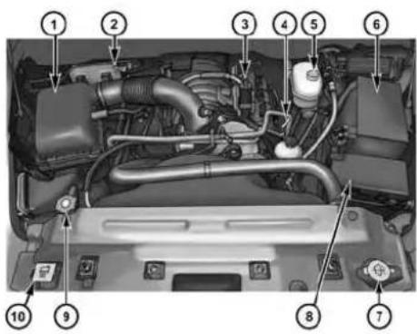
0714002445
1 — Air Cleaner Filter 6 — Battery
2 — Automatic Transmission Dipstick 7 — Washer Fluid Reservoir
3 — Engine Oil Fill 8 — Power Distribution Center (Fuses)
4 — Engine Oil Dipstick 9 — Coolant Pressure Cap
5 — Brake Fluid Reservoir 10 — Engine Coolant Reservoir
488 MAINTAINING YOUR VEHICLE
ENGINE COMPARTMENT — 6.4L
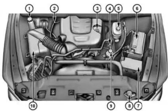
0745005289
1 — Coolant Pressure Bottle 6 — Battery
2 — Transmission Dipstick 7 — Power Distribution Center (Fuses)
3 — Engine Oil Fill 8 — Washer Solvent
4 — Engine Oil Dipstick 9 — Power Steering Fluid Reservoir
5 — Brake Fluid Reservoir 10 — Air Cleaner Filter
ONBOARD DIAGNOSTIC SYSTEM (OBD II)
Your vehicle is equipped with a sophisticated onboard diagnostic system called OBD II. This system monitors the performance of the emissions, engine, and automatic transmission control systems. When these systems are operating properly, your vehicle will provide excellent performance and fuel economy, as well as engine emissions well within current government regulations.
If any of these systems require service, the OBD II system will turn on the “Malfunction Indicator Light (MIL).” It will also store diagnostic codes and other information to assist your service technician in making repairs. Although your vehicle will usually be drivable and not need towing, see your authorized dealer for service as soon as possible.
CAUTION!
- ProlongeddrivingwiththeMILoncouldcause furtherdamagetotheemissioncontrolsystem.It couldalsoaffectfueleconomyanddriveability. Thevehiclemustbeservicedbeforeanyemissions testscanbeperformed.
- If the MILis flashing, while the engine is running, severecatalytic converter damage and power loss will soon occur. Immediately service is required.
Loose Fuel Filler Cap Message

If the vehicle diagnostic system determines that the fuel filler cap is loose, improperly installed, or damaged, a loose gascap indicator will display in the EVIC/DID telltale display
area. Refer to "Electronic Vehicle Information Center
490 MAINTAINING YOUR VEHICLE
(EVIC)" or "Driver Information Display (DID)" in "Understanding Your Instrument Panel" for further information. Tighten the fuel filler cap properly and press the SELECT button to turn off the message. If the problem continues, the message will appear the next time the vehicle is started.
A loose, improperly installed, or damaged fuel filler cap may also turn on the Malfunction Indicator Light (MIL).
EMISSIONS INSPECTION AND MAINTENANCE PROGRAMS
In some localities, it may be a legal requirement to pass an inspection of your vehicle's emissions control system. Failure to pass could prevent vehicle registration.

For states that require an Inspection and Maintenance (I/M), this check verifies the "Malfunction Indicator Light (MIL)" is functioning and is not on when the engine is running, and that the OBD II system is ready for testing.
Normally, the OBD II system will be ready. The OBD II system may not be ready if your vehicle was recently serviced, recently had a dead battery or a battery replacement. If the OBD II system should be determined not ready for the I/M test, your vehicle may fail the test.
Your vehicle has a simple ignition actuated test, which you can use prior to going to the test station. To check if your vehicle's OBD II system is ready, you must do the following:
- Cycle the ignition switch to the ON position, but do not crank or start the engine.
NOTE: If you crank or start the engine, you will have to start this test over.
-
As soon as you cycle the ignition switch to the ON position, you will see the Malfunction Indicator Light (MIL) symbol come on as part of a normal bulb check.
-
Approximately 15 seconds later, one of two things will happen:
-
The MIL will flash for about 10 seconds and then return to being fully illuminated until you turn OFF the ignition or start the engine. This means that your vehicle's OBD II system is notready and you should not proceed to the I/M station.
- The MIL will not flash at all and will remain fully illuminated until you place the ignition in the off position or start the engine. This means that your vehicle's OBD II system is ready and you can proceed to the I/M station.
If your OBD II system is notready, you should see your authorized dealer or repair facility. If your vehicle was recently serviced or had a battery failure or replacement, you may need to do nothing more than drive your vehicle as you normally would in order for your OBD II system to update. A recheck with the above test routine may then indicate that the system is nowready.
Regardless of whether your vehicle's OBD II system is ready or not, if the MIL is illuminated during normal vehicle operation you should have your vehicle serviced before going to the I/M station. The I/M station can fail your vehicle because the MIL is on with the engine running.
REPLACEMENT PARTS
Use of genuine MOPAR® parts for normal/scheduled maintenance and repairs is highly recommended to ensure the designed performance. Damage or failures caused by the use of non-MOPAR® parts for maintenance and repairs will not be covered by the New Vehicle Limited Warranty.
492 MAINTAINING YOUR VEHICLE
DEALER SERVICE
Your authorized dealer has the qualified service personnel, special tools, and equipment to perform all service operations in an expert manner. Service Manuals are available which include detailed service information for your vehicle. Refer to these Service Manuals before attempting any procedure yourself.
NOTE: Intentional tampering with emissions control systems may void your warranty and could result in civil penalties being assessed against you.
WARNING!
Youcanbebadlyinjuredworkingonorarounda motorvehicle.Onlydoserviceworkforwhichyou havetheknowledgeandtheproperequipment.Ifyou haveanydoubtaboutyourabilitytoperformaservice job,takeyourvehicletoacompetentmechanic.
MAINTENANCE PROCEDURES
The pages that follow contain the required maintenance services determined by the engineers who designed your vehicle.
Besides those maintenance items specified in the fixed "Maintenance Schedule", there are other components which may require servicing or replacement in the future.
CAUTION!
- Failuretoproperlymaintainyourvehicleorperformrepairsandservicewhennecessarycould resultinmorecostlyrepairs,damagetoother componentsornegativelyimpactvehicleperformance.Immediatelyhavepotentialmalfunctions examinedbyanauthorizeddealerorqualified repaircenter.
(Continued)
CAUTION!(Continued)
- Yourvehiclehasbeenbuiltwithimprovedfluids thatprotecttheperformanceanddurabilityofyour vehicleandalsoallowextendedmaintenanceintervals.Donotusechemicalflushesinthesecomponentsasthechemicalscandamageyourengine, transmission,powersteeringorairconditioning. SuchdamageisnotcoveredbytheNewVehicle LimitedWarranty.Ifaflushisneededbecauseof componentmalfunction,useonlythespecified fluidfortheflushingprocedure.
Engine Oil
CheckingOilLevel
To assure proper lubrication of your vehicle's engine, the engine oil must be maintained at the correct level. Check the oil level at regular intervals, such as every fuel stop.
The best time to check the engine oil level is about five minutes after a fully warmed up engine is shut off.
Checking the oil while the vehicle is on level ground will improve the accuracy of the oil level readings. Always maintain the oil level within the SAFE zone on the dipstick. Adding one quart of oil when the reading is at the bottom of the SAFE zone will result in a reading at the top of the safe zone on these engines.
CAUTION!
Overfillingorunderfillingthecrankcasewillcause oilaerationorlossofoilpressure.Thiscoulddamage yourengine.
494 MAINTAINING YOUR VEHICLE
ChangeEngineOil
The oil change indicator system will remind you that it is time to take your vehicle in for scheduled maintenance. Refer to the “Maintenance Schedule” for further information.
NOTE: Undernocircumstances should oilchange intervals exceed 8,000 miles (13,000 km) ortwelvemonths, whichever occurs first.
EngineOilSelection—5.7LEngine
For best performance and maximum protection under all types of operating conditions, the manufacturer only recommends engine oils that are API Certified and meet the requirements of Chrysler Material Standard MS-6395.
EngineOilSelection—6.4LEngine
For best performance and maximum protection under all types of operating conditions, the manufacturer only recommends engine oils that are API Certified and meet the requirements of Chrysler Material Standard MS-12633.
AmericanPetroleumInstitute(API)EngineOil IdentificationSymbol

This symbol means that the oil has been certified by the American Petroleum Institute (API). The manufacturer only recommends API Certified engine oils.
CAUTION!
Donotusechemicalflushesinyourengineoilasthe chemicalscandamageyoureengine.Suchdamageis notcoveredbytheNewVehicleLimitedWarranty.
EngineOilViscosity—5.7LEngine
MOPAR® SAE 5W-20 engine oil or equivalent Pennzoil® or Shell Helix® is recommended for all operating temperatures. This engine oil improves low temperature starting and vehicle fuel economy.
For information on engine oil filler cap location, refer to "Engine Compartment" in "Maintaining Your Vehicle" for further information.
Lubricants which do not have both the engine oil certification mark and the correct SAE viscosity grade number should not be used.
NOTE: For trucks with a 5.7L engine operating under a gross combined weight rating of 14,000 lbs (6 350 kg) or greater, MOPAR® SAE 5W-30 engine oil or equivalent Pennzoil® or Shell Helix® is recommended for all operating temperatures.
EngineOilViscosity—6.4LEngine
Use Pennzoil Ultra™ 0W-40 engine or equivalent MOPAR® oil meeting the Chrysler Material Standard MS-12633 for use in all operating temperatures.
The engine oil filler cap also shows the recommended engine oil viscosity for your engine. For information on engine oil filler cap location, refer to the “Engine Compartment” in this section.
496 MAINTAINING YOUR VEHICLE
SyntheticEngineOils
You may use synthetic engine oils provided the recommended oil quality requirements are met, and the recommended maintenance intervals for oil and filter changes are followed.
DisposingOfUsedEngineOilAndOilFilters
Care should be taken in disposing of used engine oil and oil filters from your vehicle. Used oil and oil filters, indiscriminately discarded, can present a problem to the environment. Contact your authorized dealer, service station or governmental agency for advice on how and where used oil and oil filters can be safely discarded in your area.
Engine Oil Filter
The engine oil filter should be replaced with a new filter at every engine oil change.
EngineOilFilterSelection
The manufacturer's engines have a full-flow type oil filter. Use a filter of this type for replacement. The quality of replacement filters varies considerably. Only high-quality filters should be used to assure most efficient service. MOPAR® engine oil filters are a high-quality oil filter and are recommended.
Engine Air Cleaner Filter
Refer to the “Maintenance Schedule” for the proper maintenance intervals.
WARNING!
Theairinductionsystem(aircleaner,hoses,etc.)can provide a measure of protection in the case of engine backfire. Donotremovetheairinduction system (air cleaner, hoses,etc.) unless such removal is necessary
(Continued)
WARNING!(Continued)
forrepairormaintenance.Makesurethatnooneis neartheenginecompartmentbeforestartingthe vehiclewiththeairinductionsystem(aircleaner, hoses,etc.)removed.Failureretodosocanresultin seriouspersonalinjury.
EngineAirCleanerFilterSelection
The quality of replacement engine air cleaner filters varies considerably. Only high quality filters should be used to assure most efficient service. MOPAR® engine air cleaner filters are a high quality filter and are recommended.
EngineAirCleanerFilterInspection and Replacement
Inspect engine air cleaner filter for dirt and or debris, if you find evidence of either dirt or debris you should change your air cleaner filter.
EngineAirCleanerFilterRemoval
- Release the spring clips from the air cleaner cover.
498 MAINTAINING YOUR VEHICLE

5.7LAirCleanerFilterCover

6.4LAirCleanerFilterCover
1 — Clean Air Hose Clamp
2 — Air Hose
3 — Spring Clips
1 — Clean Air Hose Clamp
2 — Spring Clips
- Lift the air cleaner cover to access the air cleaner filter.
MAINTAINING YOUR VEHICLE 499

OpenAirCleanerFilterAssembly
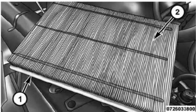
natural_image
Close-up of a textured fabric or material sample with numbered annotations (1, 2), no readable text or symbols present.AirCleanerFilter
1 — Air Cleaner Cover
2 — Air Cleaner Filter
1 — Air Cleaner Filter
2 — Air Cleaner Filter Inspection Surface
- Remove the air cleaner filter element from the housing assembly.
500 MAINTAINING YOUR VEHICLE
EngineAirCleanerFilterInstallation
NOTE: Inspect and clean the housing if dirt or debris is present before replacing the air filter element.
- Install the air cleaner filter element into the housing assembly with the air cleaner filter inspection surface facing downward.
- Install the air cleaner cover onto the housing assembly locating tabs.
- Latch the spring clips and lock the air cleaner cover to the housing assembly.
Accessory Drive Belt Inspection
WARNING!
- Donotattempttoinspectanaccessorydrivebelt withvehiclerunning.
WARNING!(Continued)
- When working near the radiator cooling fan, disconnect the fan motor lead. The fan is temperature controlled and can start at any time regardless of ignition switch position. You could be injured by themoving fan blades.
- You can be badly injured working on or around a motor vehicle. Only doservicework for which you have the knowledge and the properequipment. If you have any doubt about your ability to perform a service job, take your vehicle to a competent mechanic.
When inspecting accessory drive belts, small cracks that run across ribbed surface of belt from rib to rib, are considered normal. These are not a reason to replace belt. However, cracks running along a rib (not across) are not
(Continued)
normal. Any belt with cracks running along a rib must be replaced. Also have the belt replaced if it has excessive wear, frayed cords or severe glazing.
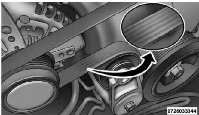
natural_image
Mechanical assembly diagram showing internal components and a magnified inset of a component (no text or symbols)AccessoryBelt(SerpentineBelt)
Conditions that would require replacement:
- Rib chunking (one or more ribs has separated from belt body)
- Rib or belt wear
- Longitudinal belt cracking (cracks between two ribs)
- Belt slips
- "Groove jumping"(belt does not maintain correct position on pulley)
- Belt broken (note: identify and correct problem before new belt is installed)
- Noise (objectionable squeal, squeak, or rumble is heard or felt while drive belt is in operation)
Some conditions can be caused by a faulty component such as a belt pulley. Belt pulleys should be carefully inspected for damage and proper alignment.
Belt replacement on some models requires the use of special tools, we recommend having your vehicle serviced at an authorized dealer.
502 MAINTAINING YOUR VEHICLE
Maintenance-Free Battery
Your vehicle is equipped with a maintenance-free battery. You will never have to add water, nor is periodic maintenance required.
WARNING!
- Batteryfluidisacorrosiveacidsolutionandcan burnorevenblindyou.Donotallowbatteryfluid tocontactyoureyes,skin,orclothing.Donotlean overabatterywhenattachingclamps.Ifacid splashesineyesoronskin,flushtheareimmediatelywithlargeamountsofwater.Referto "Jump-StartingProcedures"in"WhatToDoIn Emergencies"forfurtherinformation.
WARNING!(Continued)
- Batterygasisflammableandexplosive.Keep flameorsparksawayfromthebattery.Donotuse aboosterbatteryoranyotherboostersourcewith anoutputgreaterthan12Volts.Donotallowcable clampstotoucheachother.
- Batteryposts, terminals, and related accessories contain lead and lead compounds. Washhands after handling.
(Continued)
CAUTION!
- It is essential when replacing the cables on the battery that the positive cable is attached to the positive post and then negative cable is attached to the negative post. Battery posts are marked positive (+) and negative (-) and are identified on the battery case. Cable clamp should be ignition on the terminal posts and free of corrosion.
- Ifa "fastcharger" is used while the battery is in the vehicle, disconnect both vehicle battery cables before connecting the charger to the battery. Donot use a "fastcharger" to provide starting voltage.
Air Conditioner Maintenance
For best possible performance, your air conditioner should be checked and serviced by an authorized dealer at the start of each warm season. This service should include
cleaning of the condenser fins and a performance test. Drive belt tension should also be checked at this time.
WARNING!
- Useonlyrefrigerantsandcompressorlubricants approvedbythemanufacturerforyourairconditioningsystem.Someunapprovedrefrigerantsare flammableandcanexplode,injuringyou.Other unapprovedrefrigerantsorlubricantscancausethe systemtofail,requiringcostlyrepairs.Referto WarrantyInformationBook,locatedontheDVD, forfurtherwarrantyinformation.
- The airconditioningsystem contains refrigerant underhighpressure. To avoid risk of personal injury or damage to the system, adding refrigerant or any repair requiring linestobedisconnected should be done by an experienced technician.
CAUTION!
Donotusechemicalflushesinyourairconditioning systemasthechemicalscandamageyourairconditioningcomponents.Suchdamageisnotcoveredby theNewVehicleLimitedWarranty.
RefrigerantRecoveryAndRecyclingR134a—IfEquipped
R-134a Air Conditioning Refrigerant is a hydrofluorocarbon (HFC) that is endorsed by the Environmental Protection Agency and is an ozone-saving product. However, the manufacturer recommends that air conditioning service be performed by authorized dealer or other service facilities using recovery and recycling equipment.
NOTE: Use only manufacturer approved A/C system PAG compressor oil and refrigerants.
Refrigerant Recovery And Recycling HFO1234yf—If Equipped
HFO 1234yf Air Conditioning Refrigerant is a hydrofluorocarbon (HFC) that is endorsed by the Environmental Protection Agency and is an ozone-saving product with a low GWP (Global Warming Potential). However, the manufacturer recommends that air conditioning service be performed by authorized dealer or other service facilities using recovery and recycling equipment.
NOTE: Use only manufacturer approved A/C system PAG compressor oil and refrigerants.
Front Prop Shaft Lubrication — Four-Wheel Drive Models
Lubricate the front driveshaft grease fitting at each oil change. Refer to the “Maintenance Schedule” for the proper maintenance intervals. Use MOPAR® Type MS-6560 (lithium-based grease), or equivalent.
Body Lubrication
Locks and all body pivot points, including such items as seat tracks, door hinge pivot points and rollers, liftgate, tailgate, decklid, sliding doors and hood hinges, should be lubricated periodically with a lithium based grease, such as MOPAR® Spray White Lube to assure quiet, easy operation and to protect against rust and wear. Prior to the application of any lubricant, the parts concerned should be wiped clean to remove dust and grit; after lubricating excess oil and grease should be removed.
Particular attention should also be given to hood latching components to ensure proper function. When performing other underhood services, the hood latch, release mechanism and safety catch should be cleaned and lubricated.
The external lock cylinders should be lubricated twice a year, preferably in the Fall and Spring. Apply a small amount of a high quality lubricant, such as MOPAR® Lock Cylinder Lubricant directly into the lock cylinder.
Windshield Wiper Blades
Clean the rubber edges of the wiper blades and the windshield periodically with a sponge or soft cloth and a mild nonabrasive cleaner. This will remove accumulations of salt or road film.
Operation of the wipers on dry glass for long periods may cause deterioration of the wiper blades. Always use washer fluid when using the wipers to remove salt or dirt from a dry windshield.
Avoid using the wiper blades to remove frost or ice from the windshield. Keep the blade rubber out of contact with petroleum products such as engine oil, gasoline, etc.
NOTE: Life expectancy of wiper blades varies depending on geographical area and frequency of use. Poor performance of blades may be present with chattering, marks, water lines or wet spots. If any of these conditions are present, clean the wiper blades or replace as necessary.
506 MAINTAINING YOUR VEHICLE
The wiper blades and wiper arms should be inspected periodically, not just when wiper performance problems are experienced. This inspection should include the following points:
- Wear Or Uneven Edges
- Foreign Material
- Hardening Or Cracking
- Deformation Or Fatigue
If a wiper blade or wiper arm is damaged, replace the affected wiper arm or blade with a new unit. Do not attempt to repair a wiper arm or blade that is damaged.
WiperBladeRemoval/Installation
CAUTION!
Donotallowthewiperarmtospringbackagainst theglasswithoutthewiperbladeinplaceortheglass maybedamaged.
- Lift the wiper arm to raise the wiper blade off of the glass, until the wiper arm is in the full up position.

WiperBladeWithReleaseTabInLockedPosition
1—WiperBlade
2 — WiperArm
3 — Release Tab
MAINTAINING YOUR VEHICLE 507
- To disengage the wiper blade from the wiper arm, press the release tab on the wiper blade and while holding the wiper arm with one hand, slide the wiper blade down towards the base of the wiper arm.
508 MAINTAINING YOUR VEHICLE
- With the wiper blade disengaged, remove the wiper blade from the wiper arm.
WiperBladeWithReleaseTabInUnlockedPosition
1 — Wiper Blade
2 — WiperArm
3 — Release Tab
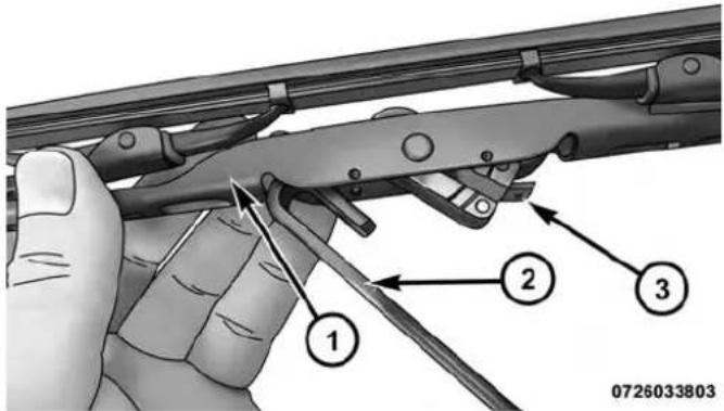
WiperBladeRemovedFromWiperArm
1—WiperBlade
2 — WiperArm
3 — Release Tab
- Gently lower the wiper arm onto the glass.
InstallingTheFrontWipers
- Lift the wiper arm off of the glass, until the wiper arm is in the full up position.
- Position the wiper blade near the hook on the tip of the wiper arm.
- Insert the hook on the tip of the arm through the opening in the wiper blade.
- Slide the wiper blade up into the hook on the wiper arm, latch engagement will be accompanied by an audible click.
- Gently lower the wiper blade onto the glass.
510 MAINTAINING YOUR VEHICLE
Adding Washer Fluid
The fluid reservoir is located under the hood and should be checked for fluid level at regular intervals. Fill the reservoir with windshield washer solvent only (not radiator antifreeze). When refilling the washer fluid reservoir, take some washer fluid and apply it to a cloth or towel and wipe the wiper blades clean. This will help blade performance.
To prevent freeze-up of your windshield washer system in cold weather, select a solution or mixture that meets or exceeds the temperature range of your climate. This rating information can be found on most washer fluid containers.
WARNING!
Commerciallyavailablewindshieldwashersolvents areflammable. They could ignite and burn you. Care must be exercised when filling or working around the washers solution.
After the engine has warmed up, operate the defroster for a few minutes to reduce the possibility of smearing or freezing the fluid on the cold windshield. Windshield washer solution used with water as directed on the container, aids cleaning action, reduces the freezing point to avoid line clogging, and is not harmful to paint or trim.
Exhaust System
The best protection against carbon monoxide entry into the vehicle body is a properly maintained engine exhaust system.
If you notice a change in the sound of the exhaust system; or if the exhaust fumes can be detected inside the vehicle; or when the underside or rear of the vehicle is damaged; have an authorized technician inspect the complete exhaust system and adjacent body areas for broken, damaged, deteriorated, or mispositioned parts. Open seams or loose connections could permit exhaust fumes to seep into the passenger compartment. In addition, have the exhaust system inspected each time the vehicle is raised for lubrication or oil change. Replace as required.
WARNING!
- Exhaustgasescaninjureorkill. They contain carbonmonoxide(CO), which is colorless and odorless. Breathing it can make you unconscious and can eventually poison you. To avoid breathing CO, refer to "Safety Tips/ExhaustGas" in "Things To Know Before Starting Your Vehicle" for further information.
- Ahotexhaustsystemcanstartafireifyoupark overmaterialsthatcanburn.Suchmaterialsmight begrassorleavescomingintocontactwithyour exhaustsystem.Donotparkoroperateyourvehicleinareaswhereyourehaustsystemcancontactanythingthatcanburn.
CAUTION!
- The catalytic converter requires the use of un-leaded fuel only. Leaded gasoline will destroy the effectiveness of the catalyst as an emissions control device and may seriously reduce engine performance and causes serious damage to the engine.
- Damagethecatalyticconvertercanresultifyour vehicleisnotkeptinproperoperatingcondition. Intheeventofenginemalfunction, particularly involvingenginemisfireorotherapparentlossof performance, haveyourvehicleservicedpromptly. Continuedoperationofyourvehiclewithasevere malfunctioncouldcausetheconvertertooverheat, resultinginpossibledamagetheconverterand vehicle.
Under normal operating conditions, the catalytic converter will not require maintenance. However, it is important to keep the engine properly tuned to assure proper catalyst operation and prevent possible catalyst damage.
NOTE: Intentional tampering with emissions control systems can result in civil penalties being assessed against you.
In unusual situations involving grossly malfunctioning engine operation, a scorching odor may suggest severe and abnormal catalyst overheating. If this occurs, stop the vehicle, turn off the engine and allow it to cool. Service, including a tune-up to manufacturer's specifications, should be obtained immediately.
To minimize the possibility of catalytic converter damage:
- Do not shut off the engine or interrupt the ignition, when the transmission is in gear and the vehicle is in motion.
- Do not try to start the engine by pushing or towing the vehicle.
- Do not idle the engine with any spark plug wires disconnected or removed, such as when diagnostic testing, or for prolonged periods during very rough idle or malfunctioning operating conditions.
Cooling System
WARNING!
Youorotherscanbebadlyburnedbyhotengine coolant(antifreeze)orsteamfromyourradiator.If youseeorhearsteamcomingfromunderthehood, donotopenthehooduntiltheradiatorhashadtime tocool.Nevertrytoopenacoolingsystempressure capwhentheradiatorishot.
EngineCoolantChecks
Check the engine coolant (antifreeze) protection every 12 months (before the onset of freezing weather, where applicable). If the engine coolant (antifreeze) is dirty or rusty in appearance, the system should be drained, flushed and refilled with fresh coolant. Check the front of the A/C condenser (if equipped) or radiator for any accumulation of bugs, leaves, etc. If dirty, clean by gently
514 MAINTAINING YOUR VEHICLE
spraying water from a garden hose vertically down the face of the A/C condenser (if equipped) or the back of the radiator core.
Check the engine cooling system hoses for brittle rubber, cracking, tears, cuts and tightness of the connection at the coolant recovery bottle and radiator. Inspect the entire system for leaks.
With the engine at normal operating temperature (but not running), check the cooling system pressure cap for proper vacuum sealing by draining a small amount of engine coolant (antifreeze) from the radiator drain cock. The radiator drain cock is located in the lower radiator tank. If the cap is sealing properly, the engine coolant (antifreeze) will begin to drain from the coolant expansion bottle. DO NOT REMOVE THE COOLANT PRESSURE CAP WHEN THE COOLING SYSTEM IS HOT.
CoolingSystem—DrainFlushAndRefill
If the engine coolant (antifreeze) is dirty or contains a considerable amount of sediment, clean and flush with a reliable cooling system cleaner. Follow with a thorough rinsing to remove all deposits and chemicals. Properly dispose of old engine coolant (antifreeze).
Refer to the “Maintenance Schedule” for the proper maintenance intervals.
SelectionOfCoolant
Refer to "Fluids, Lubricants, and Genuine Parts" in "Maintaining Your Vehicle" for further information.
CAUTION!
- Mixingofenginecoolant(antifreeze)otherthan specifiedOrganicAdditiveTechnology(OAT)enginecoolant(antifreeze),mayresultinengine damageandmaydecreasecorrosionprotection. OrganicAdditiveTechnology(OAT)enginecoolantisdifferentandshouldnotbemixedwith HybridOrganicAdditiveTechnology(HOAT)enginecoolant(antifreeze)orany"globallycompatible"coolant(antifreeze).Ifanon-OATengine coolant(antifreeze)isintroducedintothecooling systeminanemergency,thecoolingsystemwill needtobedrained,flushed,andrefilledwithfresh OATcoolant(conformingtoMS.90032),byanauthorizeddealerassoonaspossible.
(Continued)
CAUTION!(Continued)
- Donotusewateraloneoralcohol-basedengine coolant(antifreeze)products.Donotuseadditional rustinhibitorsorantirustproducts,astheymaynot becompatiblewiththeradiatorenginecoolantand mayplugtheradiator.
- This vehicle has not been designed for use with propylene glycol-based engine coolant (antifreeze). Use of propylene glycol-based engine coolant (antifreeze) is not recommended.
AddingCoolant
Your vehicle has been built with an improved engine coolant (OAT coolant conforming to MS.90032) that allows extended maintenance intervals. This engine coolant (antifreeze) can be used up to ten years or 150,000 miles (240,000 km) before replacement. To prevent reducing this extended maintenance period, it is important that
516 MAINTAINING YOUR VEHICLE
you use the same engine coolant (OAT coolant conforming to MS.90032) throughout the life of your vehicle.
Please review these recommendations for using Organic Additive Technology (OAT) engine coolant (antifreeze) that meets the requirements of Chrysler Material Standard MS.90032. When adding engine coolant (antifreeze):
- We recommend using MOPAR® Antifreeze/Coolant 10 Year/150,000 Mile Formula OAT (Organic Additive Technology) that meets the requirements of Chrysler Material Standard MS.90032.
- Mix a minimum solution of 50% OAT engine coolant that meets the requirements of Chrysler Material Standard MS.90032 and distilled water. Use higher concentrations (not to exceed 70% ) if temperatures below -34^ (-37^) are anticipated.
- Use only high purity water such as distilled or deionized water when mixing the water/engine coolant (antifreeze) solution. The use of lower quality water will reduce the amount of corrosion protection in the engine cooling system.
Please note that it is the owner's responsibility to maintain the proper level of protection against freezing according to the temperatures occurring in the area where the vehicle is operated.
NOTE:
- Some vehicles require special tools to add coolant properly. Failure to fill these systems properly could lead to severe internal engine damage. If any coolant is needed to be added to the system please contact your local authorized dealer.
- Mixing engine coolant (antifreeze) types is not recommended and can result in cooling system damage. If HOAT and OAT coolant are mixed in an emergency, have a authorized dealer drain, flush, and refill with OAT coolant (conforming to MS.90032) as soon as possible.
CoolingSystemPressureCap
The cap must be fully tightened to prevent loss of engine coolant (antifreeze), and to ensure that the engine coolant (antifreeze) will return to the radiator from the coolant expansion bottle.
The cap should be inspected and cleaned if there is any accumulation of foreign material on the sealing surfaces.
WARNING!
- Donotopenhotenginecoolingsystem. Neveradd enginecoolant (antifreeze) when the engine is overheated. Donotloosenorremovethecaptocool anoverheated engine. Heat causes pressure to buildup in the coolingsystem. Topreventscalding or injury, donotremovethe pressure cap while the system is hot or under pressure.
- Donotuseapressurecapotherthantheone specifiedforyourvehicle.Personalinjuryorenginedamagemayresult.
518 MAINTAINING YOUR VEHICLE
DisposalOfUsedEngineCoolant
Used ethylene glycol-based engine coolant (antifreeze) is a regulated substance requiring proper disposal. Check with your local authorities to determine the disposal rules for your community. To prevent ingestion by animals or children, do not store ethylene glycol-based engine coolant (antifreeze) in open containers or allow it to remain in puddles on the ground. If ingested by a child or pet, seek emergency assistance immediately. Clean up any ground spills immediately.
CheckingCoolantLevel-5.7LEngine
With the engine OFF and cold, the level of the engine coolant should be between the MIN and MAX range on the dipstick.
To check the coolant level:
- Open the coolant reservoir.

natural_image
Close-up of a mechanical component with two bolts and a separate square base, no visible text or symbolsOpeningTheCoolantReservoir
- Lift and remove the plastic dipstick from the reservoir neck.
MAINTAINING YOUR VEHICLE 519
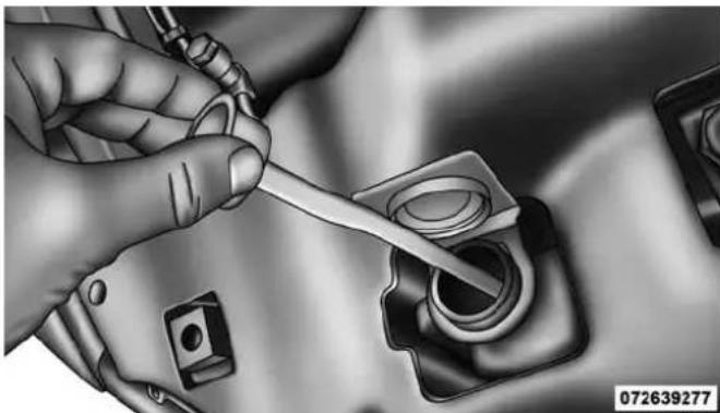
natural_image
Close-up of hands using a tool to adjust or install a mechanical component (no visible text or symbols)CoolantReservoirDipstick
- Check the coolant level on the dipstick.
The radiator normally remains completely full, so there is no need to remove the radiator cap unless checking for engine coolant (antifreeze) freeze point or replacing engine coolant (antifreeze). Advise your service attendant of this. As long as the engine operating temperature is satisfactory, the coolant bottle need only be checked once a month.
When additional engine coolant (antifreeze) is needed to maintain the proper level, it should be added to the coolant bottle. Do not overfill.
CheckingCoolantLevel—6.4LEngine
The level of the coolant in the pressurized coolant bottle should be between the "MIN" and "MAX" range on the bottle when the engine is cold.
The radiator normally remains completely full, so there is no need to remove the cap unless checking for coolant freeze point or replacing engine coolant (antifreeze). Advise your service attendant of this. As long as the engine operating temperature is satisfactory, the coolant
520 MAINTAINING YOUR VEHICLE
bottle need only be checked once a month. When additional engine coolant (antifreeze) is needed to maintain the proper level, it should be added to the coolant bottle. Do not overfill.
PointsToRemember
NOTE: When the vehicle is stopped after a few miles/ kilometers of operation, you may observe vapor coming from the front of the engine compartment. This is normally a result of moisture from rain, snow, or high humidity accumulating on the radiator and being vaporized when the thermostat opens, allowing hot engine coolant (antifreeze) to enter the radiator.
If an examination of your engine compartment shows no evidence of radiator or hose leaks, the vehicle may be safely driven. The vapor will soon dissipate.
- Do not overfill the coolant expansion bottle.
- Check the coolant freeze point in the radiator and in the coolant expansion bottle. If engine coolant (anti-freeze) needs to be added, the contents of the coolant expansion bottle must also be protected against freezing.
- If frequent engine coolant (antifreeze) additions are required, the cooling system should be pressure tested for leaks.
- Maintain engine coolant (antifreeze) concentration at a minimum of 50% OAT coolant (conforming to MS.90032) and distilled water for proper corrosion protection of your engine which contains aluminum components.
- Make sure that the coolant expansion bottle overflow hoses are not kinked or obstructed.
- Keep the front of the radiator clean. If your vehicle is equipped with air conditioning, keep the front of the condenser clean.
- Do not change the thermostat for Summer or Winter operation. If replacement is ever necessary, install ONLY the correct type thermostat. Other designs may result in unsatisfactory engine coolant (antifreeze) performance, poor gas mileage, and increased emissions.
Brake System
In order to assure brake system performance, all brake system components should be inspected periodically. Refer to the “Maintenance Schedule” for the proper maintenance intervals.
WARNING!
Ridingthebrakescanleadtobrakefailureand possiblyacollision.Drivingwithyourfootrestingor ridingonthebrakepedalcanresultinabnormally
WARNING!(Continued)
highbraketemperatures,excessiveliningwear,and possiblebrakedamage.Youwouldnothaveyourfull brakingcapacityinanemergency.
BrakeFluidLevelCheck
The fluid level of the master cylinder should be checked when performing under the hood service or immediately if the brake system warning lamp indicates system failure.
The brake master cylinder has a translucent plastic reservoir. On the outboard side of the reservoir, there is a "MAX" dot and an "MIN" dot. The fluid level must be kept within these two dots. Do not add fluid above the MAX mark because leakage may occur at the cap.
(Continued)
522 MAINTAINING YOUR VEHICLE
With disc brakes the fluid level can be expected to fall as the brake linings wear. However, an unexpected drop in fluid level may be caused by a leak and a system check should be conducted.
Use only the manufacturer's recommended brake fluid. Refer to "Fluids, Lubricants, and Genuine Parts" in "Maintaining Your Vehicle" for further information.
WARNING!
- Useonlymanufacturer's recommended brakefluid. Referto "Fluids, Lubricants, and Genuine Parts" in "Maintaining Your Vehicle" for further information. Using the wrong type of brakefluid can severely damage your brakesystem and/or impair its performance. The property of brakefluid for your vehicle is also identified on the original factory installed hydraulic master cylinder reservoir.
WARNING!(Continued)
- To avoid contamination from foreign matter or moisture, use only new brake fluidor fluid thathas been in atightly closed container. Keep them master cylinder reservoir arc apsecured at all times. Brake fluidina open container absorbsmoisture from the air resulting in alower boiling point. This may cause it to boil unexpectedly during hard or prolonged braking, resulting in sudden brake failure. This could result in a collision.
• Overfillingthebrakefluidreservoircanresultin spillingbrakefluidonhotengineparts, causing thebrakefluidtocatchfire. Brakefluidcanalso damagepaintedandvinylsurfaces, careshouldbe takentoavoiditscontactwiththesesurfaces.
(Continued)
(Continued)
WARNING!(Continued)
- Donotallowpetroleumbasedfluidtocontaminate thebrakefluid.Brakesealcomponentscouldbe damaged,causingpartialorcompletebrakefailure. Thiscouldresultinacollision.
Rear Axle And 4x4 Front Driving Axle Fluid Level
For models with 9.25 in Front Axles and 11.5 in Rear Axles, refer to "Fluids, Lubricants, and Genuine Parts" in "Maintaining Your Vehicle" for further information. For normal service, periodic fluid level checks are not required. When the vehicle is serviced for other reasons, the exterior surfaces of the axle assembly should be inspected.
When checking the fluid level (4500/5500 only), the vehicle should be in a level position. The fluid level should be 14 in ±14 in (6.4 mm ± 6.4 mm) below the fill hole on the front axle. The fluid level should be level with the bottom of the fill hole on the rear axle.
DrainAndRefill
On 4500/5500 vehicles, remove the lower bolt to drain the axle fluid.

1 — 4500/5500 Rear Axle Fluid Fill Plug 2 — 4500/5500 Rear Axle Fluid Drain Plug
524 MAINTAINING YOUR VEHICLE
Refer to the "Maintenance Schedule" for the proper maintenance intervals.
LubricantSelection
Refer to "Fluids, Lubricants, and Genuine Parts" in "Maintaining Your Vehicle" for further information.
NOTE: The presence of water in the gear lubricant will result in corrosion and possible failure of differential components. Operation of the vehicle in water, as may be encountered in some off-highway types of service, will require draining and refilling the axle to avoid damage.
Limited-SlipDifferentialsDONOTREQUIREany limited slip oil additive (friction modifiers).
NOTE: Slight noise and mild shuddering may be evident while turning a vehicle with limited slip differential on concrete or dry pavement. These conditions should be considered normal operation of the limited slip differential.
Transfer Case
DrainAndRefill
Refer to the "Maintenance Schedule" for the proper maintenance intervals.
LubricantSelection
Refer to "Fluids, Lubricants, and Genuine Parts" in "Maintaining Your Vehicle" for further information.
FluidLevelCheck
This fluid level can be checked by removing the filler plug. The fluid level should be to the bottom edge of the filler plug hole with the vehicle in a level position.
Automatic Transmission — If Equipped
SelectionOfLubricant
It is important to use the proper transmission fluid to ensure optimum transmission performance and life. Use
only the manufacturer's specified transmission fluid. Refer to "Fluids, Lubricants, and Genuine Parts" in this section for fluid specifications. It is important to maintain the transmission fluid at the correct level using the recommended fluid. No chemical flushes should be used in any transmission; only the approved lubricant should be used.
CAUTION!
Usingatransmissionfluidotherthanthemanufac-turer'srecommendedfluidmaycausedeterioration intransmissionshiftqualityand/or torqueconverter shudder, and will require more frequent fluid and filterchanges. Referto "Fluids, Lubricants, and GenuineParts" in this section for fluids specifications.
SpecialAdditives
The manufacturer strongly recommends against using any special additives in the transmission. Automatic Transmission Fluid (ATF) is an engineered product and its performance may be impaired by supplemental additives. Therefore, do not add any fluid additives to the transmission. The only exception to this policy is the use of special dyes for diagnosing fluid leaks. Avoid using transmission sealers as they may adversely affect seals.
CAUTION!
Donotusechemicalflushesinyourtransmissionas thechemicalscandamageyourtransmissioncomponents.SuchdamageisnotcoveredbytheNew VehicleLimitedWarranty.
FluidLevelCheck
Check the fluid level when the engine is fully warmed up and the transmission fluid is at normal operating temperature. Driving with an improper fluid level will greatly reduce the life of the transmission and of the fluid. Check the fluid level whenever the vehicle is serviced.
FluidLevelCheck—Procedure
It is best to check the fluid level when the transmission is at normal operating temperature (170-180°F / 77-82°C for 66RFE transmission, or 158-176°F / 70-80°C for AS66RC transmission). This normally occurs after at least 15 miles (25 km) of driving. At normal operating temperature the fluid cannot be held comfortably between the fingertips. You can read the transmission sump temperature in the EVIC/DID display (refer to "Electronic Vehicle Information Center (EVIC)/Driver Information Display (DID)" in "Understanding Your Instrument Panel" for further information).
Use the following procedure to check the transmission fluid level properly:
- Monitor the transmission temperature using the EVIC/DID display, and operate the vehicle as required to reach the normal operating temperature. If the transmission is not functioning properly, or the vehicle cannot be driven, see the NOTE and CAUTION below about checking the fluid level at colder temperatures.
- Park the vehicle on level ground.
-
Run the engine at normal idle speed for at least 60 seconds, and leave the engine running for the rest of this procedure.
-
Fully apply the parking brake and press the brake.
- Place the shift lever momentarily into each gear position (allowing time for the transmission to fully engage in each position), ending with the transmission in PARK.
- Wipe the area around the dipstick clean to prevent dirt from entering the transmission.
- Remove the dipstick, wipe it clean and reinsert it until seated.
- Remove the dipstick again and note the fluid level on both sides. The fluid level reading is only valid if there is a solid coating of oil on both sides of the dipstick. Note that the holes in the dipstick will be full of fluid if the actual level is at or above the hole. The fluid level should be between the "HOT" (upper) reference holes on the dipstick at normal operating temperature. If the fluid level is low, add fluid through the dipstick tube
to bring it to the proper level. Donotoverfill. Use ONLY the specified fluid (see "Fluids, Lubricants, and Genuine Parts" for fluid specifications). After adding any quantity of oil through the dipstick tube, wait a minimum of two minutes for the oil to fully drain into the transmission before rechecking the fluid level.
NOTE: If it is necessary to check the transmission below the operating temperature, the fluid level should be between the two "COLD" (lower) holes on the dipstick with the fluid at 60-70°F / 16-21°C for 66RFE transmission, or 68-86°F / 20-30°C for AS66RC transmission. Only use the COLD region of the dipstick as a rough reference when setting the fluid level after a transmission service or fluid change. Re-check the fluid level, and adjust as required, once the transmission reaches normal operating temperature.
CAUTION!
If the fluid temperature is below 50^ F ( 10^ C) it may not register on the dipstick. Donot add fluid until the temperature is elevated on oughto produce an accuratereading. Run the engine at idle, in PARK, to warm the fluid.
- Reinsert the dipstick. Check for leaks. Release the parking brake.
NOTE: To prevent dirt and water from entering the transmission after checking or replenishing fluid, make sure that the dipstick cap is properly reseated. It is normal for the dipstick cap to spring back slightly from its fully seated position, as long as its seal remains engaged in the dipstick tube.
FluidAndFilterChanges
Refer to the "Maintenance Schedule" for the proper maintenance intervals.
In addition, change the fluid and filters if the fluid becomes contaminated (with water, etc.), or if the transmission is disassembled for any reason.
Appearance Care And Protection From Corrosion
ProtectionOfBodyAndPaintFromCorrosion
Vehicle body care requirements vary according to geographic locations and usage. Chemicals that make roads passable in snow and ice, and chemicals that are sprayed on trees and road surfaces during other seasons, are highly corrosive to the metal in your vehicle. Outside parking, which exposes your vehicle to airborne contaminants, road surfaces on which the vehicle is operated,
extreme hot or cold weather and other extreme conditions will have an adverse effect on paint, metal trim, and underbody protection.
The following maintenance recommendations will enable you to obtain maximum benefit from the corrosion resistance built into your vehicle.
WhatCausesCorrosion?
Corrosion is the result of deterioration or removal of paint and protective coatings from your vehicle.
The most common causes are:
- Road salt, dirt and moisture accumulation.
• Stone and gravel impact. - Insects, tree sap and tar.
- Salt in the air near seacoast localities.
- Atmospheric fallout/industrial pollutants.
Washing
- Wash your vehicle regularly. Always wash your vehicle in the shade using MOPAR® Car Wash, or a mild car wash soap, and rinse the panels completely with clear water.
- If insects, tar, or other similar deposits have accumulated on your vehicle, use MOPAR® Super Kleen Bug and Tar Remover to remove.
- Use a high quality cleaner wax, such as MOPAR® Cleaner Wax to remove road film, stains and to protect your paint finish. Take care never to scratch the paint.
- Avoid using abrasive compounds and power buffing that may diminish the gloss or thin out the paint finish.
530 MAINTAINING YOUR VEHICLE
CAUTION!
- Donotuseabrasiveorstrongcleaningmaterials suchassteelwoolorscouringpowderthatwill scratchmetalandpaintedsurfaces.
- Useofpowerwashersexceeding1,200psi(8274kPa) canresultindamageorremovalofpaintanddecals.
SpecialCare
- If you drive on salted or dusty roads or if you drive near the ocean, hose off the undercarriage at least once a month.
-
It is important that the drain holes in the lower edges of the doors, rocker panels, and trunk be kept clear and open.
-
If you detect any stone chips or scratches in the paint, touch them up immediately. The cost of such repairs is considered the responsibility of the owner.
- If your vehicle is damaged due to a collision or similar cause that destroys the paint and protective coating, have your vehicle repaired as soon as possible. The cost of such repairs is considered the responsibility of the owner.
- If you carry special cargo such as chemicals, fertilizers, de-icer salt, etc., be sure that such materials are well packaged and sealed.
- If a lot of driving is done on gravel roads, consider mud or stone shields behind each wheel.
- Use MOPAR® Touch Up Paint on scratches as soon as possible. Your authorized dealer has touch up paint to match the color of your vehicle.
WheelAndWheelTrimCare
- All wheels and wheel trim, especially aluminum and chrome plated wheels, should be cleaned regularly with a mild soap and water to prevent corrosion.
- To remove heavy soil and/or excessive brake dust, use MOPAR® Wheel Cleaner.
NOTE: If your vehicle is equipped with Dark Vapor or Black Satin Chrome wheels DO NOT USE wheel cleaners, abrasives or polishing compounds. They will permanently damage this finish and such damage is not covered by the New Vehicle Limited Warranty. USE ONLY MILD SOAP AND WATER WITH A SOFT CLOTH. Used on a regular basis this is all that is required to maintain this finish.
CAUTION!
Donotusescouringpads,steelwool,abristlebrush, ormetalpolishes.Donotuseovencleaner.These productsmaydamagethewheel'sprotectivefinish. Avoidautomaticcarwashesthatuseacidicsolutions orharshbrushesthatmaydamagethewheel'sprotectivefinish.OnlyMOPAR®WheelCleaneror equivalentisrecommended.
StainRepelFabricCleaningProcedure—IfEquipped
Stain Repel seats may be cleaned in the following manner:
- Remove as much of the stain as possible by blotting with a clean, dry towel.
- Blot any remaining stain with a clean, damp towel.
532 MAINTAINING YOUR VEHICLE
- For tough stains, apply MOPAR® Total Clean, or a mild soap solution to a clean, damp cloth and remove stain. Use a fresh, damp towel to remove soap residue.
- For grease stains, apply MOPAR® Multi-Purpose Cleaner to a clean, damp cloth and remove stain. Use a fresh, damp towel to remove soap residue.
- Do not use any harsh solvents or any other form of protectants on Stain Repel products.
InteriorCare
Use MOPAR® Total Clean to clean fabric upholstery and carpeting.
Use MOPAR® Total Clean to clean vinyl upholstery.
MOPAR® Total Clean is specifically recommended for leather upholstery.
Your leather upholstery can be best preserved by regular cleaning with a damp soft cloth. Small particles of dirt can act as an abrasive and damage the leather upholstery and should be removed promptly with a damp cloth. Stubborn soils can be removed easily with a soft cloth and MOPAR® Total Clean. Care should be taken to avoid soaking your leather upholstery with any liquid. Please do not use polishes, oils, cleaning fluids, solvents, detergents, or ammonia-based cleaners to clean your leather upholstery. Application of a leather conditioner is not required to maintain the original condition.
WARNING!
Donotusevolatilesolventsforcleaningpurposes. Manyarepotentiallyflammable,andifusedin closedareastheymaycauserespiratoryharm.
CAUTION!
DonotuseAlcoholandAlcohol-basedand/orKeton basedcleaningproductstocleanleatherseats, as damagetheseatmayresult.
CleaningHeadlights
Your vehicle is equipped with plastic headlights and fog lights that are lighter and less susceptible to stone breakage than glass headlights.
Plastic is not as scratch resistant as glass and therefore different lens cleaning procedures must be followed.
To minimize the possibility of scratching the lenses and reducing light output, avoid wiping with a dry cloth. To remove road dirt, wash with a mild soap solution followed by rinsing.
Do not use abrasive cleaning components, solvents, steel wool or other aggressive material to clean the lenses.
GlassSurfaces
All glass surfaces should be cleaned on a regular basis with MOPAR® Glass Cleaner, or any commercial household-type glass cleaner. Never use an abrasive type cleaner. Use caution when cleaning the inside rear window equipped with electric defrosters or windows equipped with radio antennas. Do not use scrapers or other sharp instrument that may scratch the elements.
When cleaning the rear view mirror, spray cleaner on the towel or rag that you are using. Do not spray cleaner directly on the mirror.
CleaningPlasticInstrumentClusterLenses
The lenses in front of the instruments in this vehicle are molded in clear plastic. When cleaning the lenses, care must be taken to avoid scratching the plastic.
534 MAINTAINING YOUR VEHICLE
- Clean with a wet soft rag. A mild soap solution may be used, but do not use high alcohol content or abrasive cleaners. If soap is used, wipe clean with a clean damp rag.
- Dry with a soft cloth.
SeatBeltMaintenance
Do not bleach, dye or clean the belts with chemical solvents or abrasive cleaners. This will weaken the fabric. Sun damage can also weaken the fabric.
If the belts need cleaning, use a mild soap solution or lukewarm water. Do not remove the belts from the car to wash them. Dry with a soft cloth.
Replace the belts if they appear frayed or worn or if the buckles do not work properly.
WARNING!
Afrayedortornbeltcouldripapartinacollisionand leaveyouwithnoprotection.Inspectthebeltsystem periodically,checkingforcuts,frays,orlooseparts. Damagedpartsmustbereplacedimmediately.Do notdisassembleormodifythesystem.Seatbelt assembliesmustbereplacedafteracollisionifthey havebeendamaged(i.e.,bentretractor,tornwebbing,etc.).
FUSES
WARNING!
- Whenreplacingablownfuse,alwaysuseanappropriatereplacementfusewiththesameamp ratingastheoriginalfuse.Neverreplaceafuse withanotherfuseofhigheramprating.Never replaceablownfusewithmetalwiresoranyother material.Failuretouseproperfusesmayresultin seriouspersonalinjury,fireand/orpropertydamage.
WARNING!(Continued)
- Before-replacingafuse, makesurethattheignition isoffandthatalltheotherservicesareswitchedoff and/ordisengaged.
- Ifthereplacedfuseblowsagain,contactanaauthorizeddealer.
- Ifageneralprotectionfuseforsafetysystems(air bagsystem,brakingsystem),powerunitsystems (enginesystem,gearboxsystem)orsteeringsystem blows,contactanauthorizeddealer.
(Continued)
Power Distribution Center
The Power Distribution Center is located in the engine compartment near the battery. This center contains cartridge fuses, micro fuses, relays, and circuit breakers. A description of each fuse and component may be stamped on the inside cover, otherwise the cavity number of each fuse is stamped on the inside cover that corresponds to the following chart.
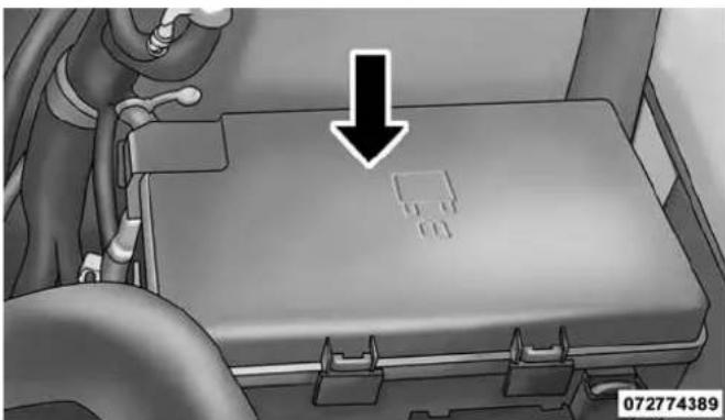
natural_image
Interior view of a vehicle chassis with a black arrow pointing to a component (no text or symbols visible)PowerDistributionCenterLocation
| CavityCartridgeFuseMicroFuseDescription | |||
| F01 80 Amp Black Rad Fan Control Module – If equipped | |||
| F03 60 Amp Yellow Rad Fan – If Equipped | |||
| F05 40 Amp Green | Compressor for Air Suspension –If Equipped | ||
| F06 40 Amp | Green Antilock Brakes | /Electronic Stability | Control Pump |
| F07 40 Amp | Green Starter Solenoid | ||
| F08 20 Amp | Blue(1500 LD/Cummins Diesel) | Emissions Diesel – If Equipped | |
| F09 40 Amp | Green(Special Services Vehicle & Cummins Diesel)30 Amp Pink(1500 LD Diesel) | Diesel Fuel Heater – If Equipped | |
| F10 40 Amp | Green Body Controller | / Exterior Lighting #2 | |
| F10 50 Amp | Red Body Controller / | Exterior Lighting #2 – | If Equipped with Stop/Start |
| F11 30 Amp | Pink Integrated Trailer | Brake Module – | If Equipped |
| F12 40 Amp Green Body Controller #3 / Interior Lights | |||
| F13 40 Amp Green Blower Motor | |||
| F14 40 Amp Green Body Controller #4 / Power Locks | |||
| F16 30 Amp Pink Smart Bar – If Equipped | |||
| F19 20 Amp Blue(1500 LD Diesel)30 Amp Pink(Cummins Diesel) | SCR – If Equipped | ||
| F20 30 Amp Pink Passenger Door Module | |||
| F21 30 Amp Pink Drive Train Control Module | |||
| F22 20 Amp Blue30 Amp Pink(Cummins Diesel) | Engine Control Module | ||
| F23 30 Amp Pink Body Controller #1 | |||
| F24 30 Amp Pink Driver Door Module | |||
| F25 30 Amp Pink Front Wiper | |||
| F26 30 Amp Pink Antilock Brakes/Stability Control Module/Valves | |||
| F28 20 Amp Blue Trailer Tow Backup Lights – If Equipped | |||
| F29 20 Amp Blue Trailer Tow Parking Lights – If Equipped | |||
| F30 30 Amp Pink Trailer Tow Receptacle | |||
| F31 30 Amp Pink(1500 LD Diesel) | Urea Heater Control – If Equipped | ||
| F32 30 Amp Pink Drive Train Control Module – If Equipped | |||
| F33 20 Amp Blue Special Services Vehicle Only | |||
| F34 30 Amp Pink Vehicle System Interface Module #2 –If Equipped | |||
| F35 30 Amp Pink | Sunroof – If Equipped | ||
| F36 30 Amp Pink | Rear Defroster– If Equipped | ||
| F37 30 Amp Pink | Cummins | Diesel Fuel Heater #2 If Equipped | |
| F38 30 Amp Pink Power Inverter 115V AC- If Equipped | |||
| F39 30 Amp Pink Vehicle System Interface Module #1- | If Equipped | ||
| F41 10 Amp Red Active Grill Shutter — If Equipped | |||
| F42 20 Amp Yellow Horn | |||
| F44 10 Amp Red Diagnostic Port | |||
| F46 10 Amp Red Tire Pressure Monitor | |||
| F49 10 Amp Red Instrument Panel Cluster | |||
| F50 20 Amp Yellow Air Suspension Control Module - If Equipped | |||
| F51 10 Amp Red Ignition Node Module / Keyless Ignition | |||
| F52 | 5 Amp Tan | Battery Sensor | |
| F53 20 Amp Yellow Trailer Tow – Left Turn/Stop Lights | |||
| F54 20 Amp Yellow | Adjustable Pedals | ||
| F56 | 15 Amp Blue | Additional Diesel Content – If Equipped | |
| F57 20 Amp Yellow Transmission | |||
| F58 20 Amp Yellow Spare Fuse | |||
| F59 10 Amp Red SCR Relay – If Equipped | |||
| F60 15 Amp Blue Underhood Lamp | |||
| F61 10 Amp Red (1500) | LD Diesel & Cummins Diesel) | PM Sensor – If Equipped | |
| F62 10 Amp Red Air Conditioning Clutch | |||
| F63 20 Amp Yellow Ignition Coils (Gas), Urea Heater | (Cummins Diesel) | ||
| F64 | 25 Amp Clear | Fuel Injectors / Powertrain | |
| F65 10 Amp Red USB interface | |||
| F66 10 Amp Red Sunroof / Passenger Window Switches / Rain Sensor | |||
| F67 10 Amp Red CD / DVD / Bluetooth Hands-free Module –If Equipped | |||
| F69 15 Amp Blue Mod SCR 12V (Cummins Diesel) – If | Equipped | ||
| F70 30 Amp Green Fuel Pump Motor | |||
| F71 25 Amp Clear Amplifier | |||
| F72 10 Amp Red Voltage Stabilizer Modules – If Equipped | |||
| F73 20 Amp Yellow Fuel Transfer Pump (HD Only) – IfEquipped | |||
| F74 20 Amp Yellow(Gas Engine &1500 LD Diesel)10 Amp Red (Cum-mins Diesel Engine) | Brake Vacuum Pump Gas/Diesel – IfEquipped | ||
| F75 10 Amp Red Coolant Temperature Valve Actuator | |||
| F76 10 Amp Red Antilock Brakes/Electronic Stability Control | |||
| F77 10 Amp Red Drivetrain Control Module/Front Axle | Disconnect Module | ||
| F78 10 Amp Red Engine Control Module / Electric Power | Steering | ||
| F79 15 Amp Blue Clearance Lights | |||
| F80 10 Amp Red Universal Garage Door Opener / Compass | |||
| F81 20 Amp Yellow Trailer Tow Right Turn/Stop Lights | |||
| F82 10 Amp Red Steering Column Control Module/Cruise | Control | ||
| F84 15 Amp Blue Switch Bank/Instrument Cluster | |||
| F85 10 Amp Red Airbag Module | |||
| F86 10 Amp Red Airbag Module | |||
| F87 10 Amp Red Air Suspension-If Equipped / Trailer Tow / Steering Column Control Module | |||
| F88 15 Amp Blue Instrument Panel Cluster | |||
| F90/F91 20 Amp Yellow | Power Outlet (Rear seats) Customer Selectable | ||
| F93 20 Amp Yellow Cigar Lighter | |||
| F94 10 Amp Red Shifter / Transfer Case Module | |||
| F95 10 Amp Red Rear Camera / Park Assist | |||
| F96 10 Amp Red Rear Seat Heater Switch | |||
| F97 25 Amp Clear Rear Heated Seats & Heated Steering Wheel | - If Equipped | ||
| F98 25 Amp Clear Front Heated Seats - If Equipped | |||
| F99 10 Amp Red | Climate Control | ||
| F100 | 10 Amp Red | Upfitters - If Equipped | |
| F101 | 15 Amp Blue | Electrochromatic Mirror / Smart High Beams- If Equipped | |
| F104 | 20 Amp Yellow | Power Outlets (Instrument Panel/Center Console) | |
CAUTION!
- Wheninstallingthepowerdistributioncenter cover,itisimportanttoensurethecoverisproperly positionedandfullylatched.Failuretodosomay allowwatertogetintothepowerdistribution centerandpossiblyresultinanelectricalsystem failure.
- Whenreplacingablownfuse,itisimportanttouse onlyafusehavingthecorrectamperagerating.The useofafusewitharatingotherthanindicatedmay resultinadangerouselectricalsystemoverload.If aproperlyratedfusecontinuestoblow,itindicates aprobleminthecircuitthatmustbecorrected.
VEHICLE STORAGE
If you are storing your vehicle for more than 21 days, we recommend that you take the following steps to minimize the drain on your vehicle's battery:
- Disconnect the negative cable from battery.
- Any time you store your vehicle or keep it out of service (i.e., vacation) for two weeks or more, run the air conditioning system at idle for about five minutes in the fresh air and high blower setting. This will ensure adequate system lubrication to minimize the possibility of compressor damage when the system is started again.
546 MAINTAINING YOUR VEHICLE
REPLACEMENT BULBS
All of the inside bulbs are brass or glass-wedge base. Aluminum base bulbs are not approved.
LIGHT BULBS — Interior
| BulbNumber | |
| Overhead Console Lamps | TS 212-2 |
| Dome Lamp 7679 | |
| For lighted switches, see your authorized dealer for replacement instructions. | |
LIGHT BULBS — Exterior
| BulbNumber | |
| Quad Headlamp – Low Beam | H11 |
| BulbNumber | |
| Quad Headlamp – High Beam | 9005 |
| Quad Headlamp – Front Turn Signal Lamp | 3157NA |
| Premium Headlamp – Low Beam | HIR2 |
| Premium Headlamp – High Beam | 9005 |
| Premium Headlamp – Front Turn Signal Lamp | LED (See authorized dealer for service) |
| Horizontal Fog Lamp 9145 | |
| Vertical Fog Lamp 9006 | |
| Cab Roof Marker Lamps 194NA | |
| Center High Mounted Stop Lamp | 921 |
| Rear Cargo Lamp 921 | |
| Box Off Tail Lamps – Stop/Turn/Tail/License Plate | 1157 |
| Box Off Tail Lamps – Back Up | 1156 |
BULB REPLACEMENT
NOTE: Lens fogging can occur under certain atmospheric conditions. This will usually clear as atmospheric conditions change to allow the condensation to change back into a vapor. Turning the lamps on will usually accelerate the clearing process.
Base Quad / Premium Bi-Halogen: Low Beam Headlamp, High Beam Headlamp, Front Park And Turn — If Equipped
- Open the hood.
- Disconnect and isolate the negative battery cable.
- Remove the six plastic push-in fasteners that secure the upper radiator seal to the grille support and both fender ledges.
- Remove the two plastic push-in rivets that secure the upper radiator seal to the radiator.
- Remove the upper radiator seal from the vehicle.
- Remove the two headlamp assembly attachment screws.
548 MAINTAINING YOUR VEHICLE

natural_image
Close-up of a mechanical component with two arrows pointing to a highlighted section (no text or symbols visible)HeadlampAssemblyAttachmentScrewLocations
-
Reach into the front wheel house ahead of the front wheel, remove the fastener, and lift the cover over the access hole in the front of the wheel house splash shield. Access to the rear of the lamp can be gained through this access hole.
-
Reach through the access hole of the wheel house splash shield and lift the slide lock upward far enough to disengage it from the lock post on the back of the front lamp unit housing.

natural_image
Mechanical component diagram showing a piston and housing assembly with bidirectional arrow indicating movement (no text or symbols)SlideLock
- Remove the headlamp assembly. Grasp the outboard edge of the lamp and pull it straight forward to disengage the ball stud from the plastic grommet.
- Disconnect the wiring harness connectors from the bulb socket.
- Replace bulb(s) as necessary.
CAUTION!
- Donotcontaminatethebulbglassbytouchingit withyourfingersorbyallowingittocontactother oilysurfaces.Shortenedbulblifewillresult.
- Alwaysusethecorrectbulbsizeandtypefor replacement.Anincorrectbulbsizeortypemay overheatandcausedamagetothelamp,thebulb socket,orthelampwiring.
MAINTAINING YOUR VEHICLE 549
NOTE: There are access covers over both headlamp bulb access holes in the quad front lamp unit housing (if equipped). These covers MUST be reinstalled after the bulb has been replaced.
Fog Lamps — If Equipped
- Reach under and behind the front bumper to access the back of the front fog lamp housing.
- Disconnect the fog lamp wiring harness connector from the fog lamp bulb.
- Rotate the bulb counterclockwise 14 turn to unlock the bulb from the housing.
- Pull the bulb straight out from the housing.
550 MAINTAINING YOUR VEHICLE
CAUTION!
Donotcontaminate the bulb glass by touching it with your fingers or by allowing it to contact other oilysurfaces. Shortened bul blifewill result.
Center High-Mounted Stoplamp (CHMSL) With Cargo Lamp
- Remove the two screws holding the housing/lens to the body as shown.
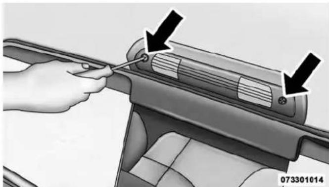
natural_image
Hand using a tool to adjust or install a car interior panel, with arrows indicating the process (no text or symbols present)CHMSLMountingScrewLocations
MAINTAINING YOUR VEHICLE 551
- Separate the connector holding the housing and wiring harness to the body.
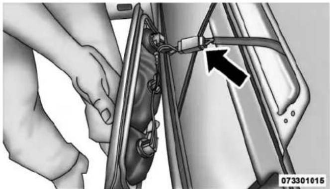
natural_image
Close-up of hands installing or adjusting a mechanical component with a black arrow pointing to a detail (no text or symbols visible)CHMSLConnectorLocation
-
Turn the desired bulb socket 14 turn and remove the socket and bulb from housing.
-
Pull the desired bulb straight from the socket.

natural_image
Close-up of hands using a tool to adjust or install a mechanical component (no visible text or symbols)CHMSLBulbAndSocket
552 MAINTAINING YOUR VEHICLE
CAUTION!
Donotcontaminatethebulbglassbytouchingit withyourfingersorbyallowingittocontactother oilysurfaces.Shortenedbulblifewillresult.
•Outside Bulbs: Cargo Lamps
•Inside Bulb: Center High-Mounted Stop Lamp
- Reverse the procedure for installation of bulbs and housing.
Cab Top Clearance Lamps — If Equipped
- Remove the two screws from the top of the lamp.
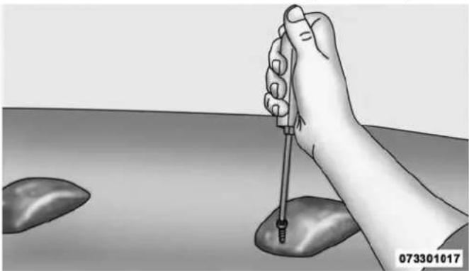
natural_image
Illustration of a hand holding a pipette over a surface with two droplets (no text or symbols)RemovingRearScrewFromClearanceLamp
MAINTAINING YOUR VEHICLE 553
- Rotate the bulb socket 14 turn and pull it from the lamp assembly.
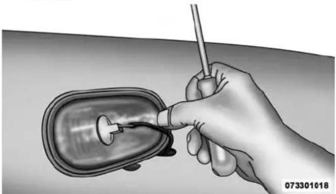
natural_image
Illustration of a hand holding a medical or laboratory instrument near a curved device (no text or symbols visible)RemovingBulbSocketFromClearanceLamp
- Pull the bulb straight from it's socket and replace.
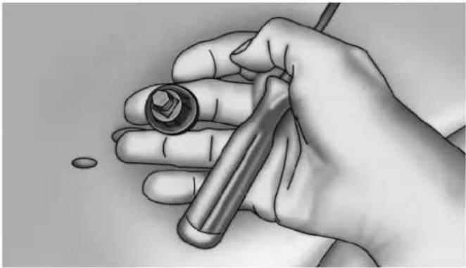
natural_image
Illustration of a hand holding a wrench and a small object, no text or symbols presentRemovingTheBulbFromTheBulbSocket
554 MAINTAINING YOUR VEHICLE
FLUID CAPACITIES
| U.S.Metric | ||
| Fuel(Approximate) | ||
| Standard Rear Tank 52 Gallons 197 Liters | ||
| Optional Midship Tank 22 Gallons 83 Liters | ||
| EngineOilWithFilter | ||
| 5.7L Engine (SAE 5W-20, API Certified) 7 Quarts 6.6 Liters | ||
| 6.4L Engine (SAE 0W-40, Synthetic API Certified) 7 Quarts 6.6 Liters | ||
| CoolingSystem | ||
| 5.7L Engine (MOPAR® Antifreeze/Coolant 10 Year/150,000 Mile Formula). | 18.3 Quarts 17.3 Liters | |
| 6.4L Engine (MOPAR® Antifreeze/Coolant 10 Year/150,000 Mile Formula). | 16.6 Quarts 15.7 Liters | |
FLUIDS, LUBRICANTS AND GENUINE PARTS
Engine
| ComponentFluid,Lubricant,orGenuinePart | |
| Engine Coolant We recommend you use MOPAR® Antifreeze/Coolant10-Year/150,000 Mile Formula OAT (Organic Additive Technology). | |
| Engine Oil – 5.7L Engine We recommend you use API Certified SAE 5W-20 Engine Oil, meeting the requirements of Chrysler Material Standard MS-6395 such as MOPAR®, Pennzoil®, and Shell Helix®. Refer to your engine oil filler cap for correct SAE grade. | |
| Engine Oil – 5.7L Engine For trucks operating under a gross combined weight rating greater than 14,000 lbs/(6,350 kg.) | We recommend you use API Certified SAE 5W-30 Engine Oil, meeting the requirements of Chrysler Material Standard MS-6395 such as MOPAR®, Pennzoil®, and Shell Helix®. Refer to your engine oil filler cap for correct SAE grade. |
556 MAINTAINING YOUR VEHICLE
| ComponentFluid,Lubricant,orGenuinePart | |
| Engine Oil – 6.4L Engine For best performance and maximum protection under all types of operating conditions, the manufacturer only recommends full synthetic engine oils that meet the American Petroleum Institute (API) categories of SN. The manufacturer recommends the use of Pennzoil UltraTM 0W-40 or equivalent MOPAR® engine oil meeting the requirements of Chrysler Material Standard MS-12633 for use in all operating temperatures. | |
| Engine Oil Filter – 5.7L/6.4L Engine We recommend you use MOPAR® Engine Oil Filters. | |
| Spark Plugs – 5.7L/6.4L Engine We recommend you use MOPAR® Spark Plugs. | |
| Fuel Selection – 5.7L/6.4L Engine 87 Octane Acceptable - 89 Octane Recommended. | |
CAUTION!
- Mixingofenginecoolant(antifreeze)otherthan specifiedOrganicAdditiveTechnology(OAT)enginecoolant(antifreeze),mayresultinengine damageandmaydecreasecorrosionprotection. OrganicAdditiveTechnology(OAT)enginecoolantisdifferentandshouldnotbemixedwith HybridOrganicAdditiveTechnology(HOAT)enginecoolant(antifreeze)orany"globallycompatible"coolant(antifreeze).Ifanon-OATengine coolant(antifreeze)isintroducedintothecooling systeminanemergency,thecoolingsystemwill needtobedrained,flushed,andrefilledwithfresh OATcoolant(conformingtoMS.90032),byanauthorizeddealerassoonaspossible.
CAUTION!(Continued)
- Donotusewateraloneoralcohol-basedengine coolant(antifreeze)products.Donotuseadditional rustinhibitorsorantirustproducts,astheymaynot becompatiblewiththeradiatorenginecoolantand mayplugtheradiator.
- This vehicle has not been designed for use with propylene glycol-based engine coolant (antifreeze). Use of propylene glycol-based engine coolant (antifreeze) is not recommended.
(Continued)
Chassis
| ComponentFluid,Lubricant,orGenuinePart | |
| Automatic Transmission (5.7L, and 6.4L Engine with 66RFE Transmission) (For Diesel Engine see Diesel Supplement) | Use only ATF+4® Automatic Transmission Fluid. Failure to use ATF+4® fluid may affect the function or performance of your transmission. We recommend MOPAR® ATF+4® fluid. |
| Automatic Transmission (6.4L Engine with AS66RC Transmission) | Use only MOPAR® ASRC Automatic Transmission Fluid or equivalent. Failure to use the proper fluid may affect the function or performance of your transmission. |
| Transfer Case We recommend you use MOPAR® BW44-44 Transfer Case Fluid. | |
| Front and Rear Axle Fluid (4500/5500) We recommend you use GL-5 SAE 75W-90 Synthetic (MS-9763). | |
| Brake Master Cylinder | We recommend you use MOPAR® DOT 3 and SAE J1703. If DOT 3 brake fluid is not available, then DOT 4 is acceptable. |
| Power Steering Reservoir | We recommend you use MOPAR® Power Steering Fluid +4, MOPAR® ATF+4® Automatic Transmission Fluid. |
MAINTENANCE SCHEDULES
CONTENTS
■ MAINTENANCE SCHEDULE .....560
□ Maintenance Chart .....562
560 MAINTENANCE SCHEDULES
MAINTENANCE SCHEDULE
Your vehicle is equipped with an automatic oil change indicator system. The oil change indicator system will remind you that it is time to take your vehicle in for scheduled maintenance.
Based on engine operation conditions, the oil change indicator message will illuminate. This means that service is required for your vehicle. Operating conditions such as frequent short-trips, trailer tow, extremely hot or cold ambient temperatures, and E85 fuel usage will influence when the “Oil Change Required” message is displayed. Severe Operating Conditions can cause the change oil message to illuminate as early as 3,500 miles (5,600 km) since last reset. Have your vehicle serviced as soon as possible, within the next 500 miles (805 km).
Your authorized dealer will reset the oil change indicator message after completing the scheduled oil change. If a scheduled oil change is performed by someone other than your authorized dealer, the message can be reset by referring to the steps described under “Electronic Vehicle Information Center (EVIC)/Driver Information Display (DID)” in “Understanding Your Instrument Panel” for further information.
NOTE:
- GasolineEngines
- Under no circumstances should oil change intervals exceed 8,000 miles (13,000 km) or twelve months, whichever comes first.
- SevereDuty
- Change Engine Oil at 4000 miles (6,500 km) if the vehicle is operated in a dusty and off road environment. This type of vehicle use is considered Severe Duty
OnceAMonthOrBeforeALongTrip:
- Check engine oil level
-
Check windshield washer fluid level
-
Check the tire inflation pressures and look for unusual wear or damage
- Check the fluid levels of the coolant reservoir, brake master cylinder, power steering and automatic transmission and fill as needed.
- Check function of all interior and exterior lights
RequiredMaintenance
Refer to the Maintenance Schedules on the following pages for required maintenance.
| AtEveryOilChangeIntervalAsIndicatedByOil ChangeIndicatorSystem: |
| •Change oil and filter. |
| •Rotate the tires. Rotate at the first sign of irregularwear,evenifitoccursbeforetheoilindicator systemturnson. |
| AtEveryOilChangeIntervalAsIndicatedByOil ChangeIndicatorSystem: |
| Inspect battery and clean and tighten terminals as required. |
| Inspect automatic transmission fluid if equipped with dipstick. |
| Inspect brake pads, shoes, rotors, drums, hoses and park brake. |
| Inspect engine cooling system protection and hoses. |
| Inspect exhaust system. |
| Inspect engine air cleaner if using in dusty or off-road conditions. |
| Lube the front drive shaft fitting. |
Maintenance Chart
| Mileage or time passed (whichever comes first) | 20,000 | 30,000 | 40,000 | 50,000 | 60,000 | 70,000 | 80,000 | 90,000 | 100,000 | 110,000 | 120,000 | 130,000 | 140,000 | 150,000 |
| Or Years: | 2 3 4 | 5 6 7 8 | 9 10 | 11 12 | 13 14 | 15 | ||||||||
| Or Kilometers: | 32,000 | 48,000 | 64,000 | 80,000 | 96,000 | 112,000 | 128,000 | 144,000 | 160,000 | 176,000 | 192,000 | 208,000 | 224,000 | 240,000 |
| Additional Inspections | ||||||||||||||
| InspecttheCV/Universaljoints.XXXXX | ||||||||||||||
| Inspectfrontsuspension,tierod ends,andreplaceifnecessary. | X | X | X | X | X | X | X | |||||||
| Inspectthefrontandrearaxle surfaces.lfgearoilleakageis suspected,checkthefluidlevel. Ifusingyourvehicleforpolice, taxi,fleet,off-roadorfrequent trailertowing,changeaxlefluid. | X | X | X | X | X | X | X | |||||||
MAINTENANCE SCHEDULES 563
| Mileage or time passed (whichever comes first) | 20,000 | 30,000 | 40,000 | 50,000 | 60,000 | 70,000 | 80,000 | 90,000 | 100,000 | 110,000 | 120,000 | 130,000 | 140,000 | 150,000 |
| Or Years: | 2 3 4 | 5 6 7 8 | 9 10 | 11 12 | 13 14 | 15 | ||||||||
| Or Kilometers: | 32,000 | 48,000 | 64,000 | 80,000 | 96,000 | 112,000 | 128,000 | 144,000 | 160,000 | 176,000 | 192,000 | 208,000 | 224,000 | 240,000 |
| Inspectthebrakelinings,parking brakefunction. | X | X | X | X | X | |||||||||
| Additional Maintenance | ||||||||||||||
| Replaceengineairfilter.XX | X | X | X | |||||||||||
| Replacesparkplugs (5.7L engine).** | X | |||||||||||||
| Replacesparkplugs (6.4L engine).** | X | |||||||||||||
| Flushandreplacetheengine coolantat10yearsor 150,000miles(240,000km) whichevercomesfirst. | X | X | ||||||||||||
X
564 MAINTENANCE SCHEDULES
| Mileage or time passed (whichever comes first) | 20,000 | 30,000 | 40,000 | 50,000 | 60,000 | 70,000 | 80,000 | 90,000 | 100,000 | 110,000 | 120,000 | 130,000 | 140,000 | 150,000 |
| Or Years: | 2 3 4 | 5 6 7 8 | 9 10 | 11 12 | 13 14 | 15 | ||||||||
| Or Kilometers: | 32,000 | 48,000 | 64,000 | 80,000 | 96,000 | 112,000 | 128,000 | 144,000 | 160,000 | 176,000 | 192,000 | 208,000 | 224,000 | 240,000 |
| Changetheautomatictransmis-sionfluid(AS66RCTransmission Only). | X | X | X | |||||||||||
| Changetheautomatictransmis-sionfluidandsumpfilter (AS66RCTransmissionOnly). | X | X | ||||||||||||
| Changetheautomatictransmis-sionfluidandfilter(s)(66RFE TransmissionOnly),ifusingyour vehicleforpolice,taxi,fleet,or frequenttrailertowing. | X | |||||||||||||
| Changetheautomatictransmis-sionfluidandfilter(s)(66RFE transmission). | X | |||||||||||||
| Inspectthetransfercasefluid, changeforanyofthefollowing: police,taxi,fleet,orfrequent trailertowing. | X | X | X | |||||||||||
| Changethetransfercasefluid.X | ||||||||||||||
| InspectandreplacePCVvalveif necessary. | X |
** The spark plug change interval is mileage based only, yearly intervals do not apply.
WARNING!
- Youcanbebadlyinjuredworkingonorarounda motorvehicle.Doonlyserviceworkforwhichyou havetheknowledgeandtherightequipment.If youhaveanydoubtaboutyourabilitytoperforma servicejob,takeyourvehicletoacompetentmechanic.
- Failuretoproperlyinspectandmaintainyourvehiclecouldresultinacomponentmalfunctionandeffectvehiclehandlingandperformance.This couldcauseanaccident.
IF YOU NEED CONSUMER ASSISTANCE
CONTENTS
■SUGGESTIONS FOR OBTAINING SERVICE FOR YOUR VEHICLE....569
□Prepare For The Appointment. . . . . . . . . . . . . . . . . . . . . . . . . . . . . . . . . . . . . . . . . . . . . . . . . . . . . . . . . . . . . . . 569
□Prepare A List....569
□Be Reasonable With Requests....569
■IF YOU NEED ASSISTANCE....569
□Chrysler Group LLC Customer Center. . . . . . .570
□Chrysler Canada Inc. Customer Center .....570
□In Mexico Contact....571
□Customer Assistance For The Hearing Or Speech Impaired (TDD/TTY) .....571
□Service Contract....571
■WARRANTY INFORMATION....572
■ MOPAR® PARTS .....573
■REPORTING SAFETY DEFECTS .....573
□In The 50 United States And Washington, D.C. . . . . . . . . . . . . . . . . . . . . . . . . . . . . . . . . . . . . . . . . . . . . . . . . . . . . . . . . . . . . . . . . . . . . . . . . . . 573
□In Canada. .573
■PUBLICATION ORDER FORMS .....574
568 IF YOU NEED CONSUMER ASSISTANCE
■DEPARTMENT OF TRANSPORTATION UNIFORM TIRE QUALITY GRADES .....575
□Treadwear. .575
□Traction Grades....575
□Temperature Grades. .576
SUGGESTIONS FOR OBTAINING SERVICE FOR YOUR VEHICLE
Prepare For The Appointment
If you are having warranty work done, be sure to have the right papers with you. Take your warranty folder. All work to be performed may not be covered by the warranty. Discuss additional charges with the service manager. Keep a maintenance log of your vehicle's service history. This can often provide a clue to the current problem.
Prepare A List
Make a written list of your vehicle's problems or the specific work you want done. If you've had an accident or work done that is not on your maintenance log, let the service advisor know.
Be Reasonable With Requests
If you list a number of items and you must have your vehicle by the end of the day, discuss the situation with the service advisor and list the items in order of priority. At many authorized dealers, you may obtain a rental vehicle at a minimal daily charge. If you need a rental, it is advisable to make these arrangements when you call for an appointment.
IF YOU NEED ASSISTANCE
The manufacturer and its authorized dealer are vitally interested in your satisfaction. We want you to be happy with our products and services.
Warranty service must be done by an authorized dealer. We strongly recommend that you take the vehicle to an authorized dealer. They know your vehicle the best, and are most concerned that you get prompt and high quality service. The manufacturer's authorized dealer have the
570 IF YOU NEED CONSUMER ASSISTANCE
facilities, factory-trained technicians, special tools, and the latest information to ensure the vehicle is fixed correctly and in a timely manner.
This is why you should always talk to an authorized dealer service manager first. Most matters can be resolved with this process.
- If for some reason you are still not satisfied, talk to the general manager or owner of the authorized dealer. They want to know if you need assistance.
- If an authorized dealer is unable to resolve the concern, you may contact the manufacturer's customer center.
Any communication to the manufacturer's customer center should include the following information:
- Owner's name and address
-
Owner's telephone number (home and office)
-
Authorized dealer name
• Vehicle Identification Number (VIN)
• Vehicle delivery date and mileage
Chrysler Group LLC Customer Center
P.O. Box 21-8004
Auburn Hills, MI 48321-8004
Phone: (866) 726-4636
Chrysler Canada Inc. Customer Center
P.O. Box 1621
Windsor, Ontario N9A 4H6
Phone: (800) 465-2001 English / (800) 387-9983 French
In Mexico Contact
In Mexico City: 5081-7568
Outside Mexico City: 1-800-505-1300
Customer Assistance For The Hearing Or Speech Impaired (TDD/TTY)
To assist customers who have hearing difficulties, the manufacturer has installed special TDD (Telecommunication Devices for the Deaf) equipment at its customer center. Any hearing or speech impaired customer, who has access to a TDD or a conventional teletypewriter (TTY) in the United States, can communicate with the manufacturer by dialing 1–800–380–CHRY.
IF YOU NEED CONSUMER ASSISTANCE 571
Canadian residents with hearing difficulties that require assistance can use the special needs relay service offered by Bell Canada. For TTY teletypewriter users, dial 711 and for Voice callers, dial 1-800-855-0511 to connect with a Bell Relay Service operator.
Service Contract
You may have purchased a service contract for a vehicle to help protect you from the high cost of unexpected repairs after the manufacturer's New Vehicle Limited Warranty expires. The manufacturer stands behind only the manufacturer's service contracts. If you purchased a manufacturer's service contract, you will receive Plan Provisions and an Owner Identification Card in the mail within three weeks of the vehicle delivery date. If you have any questions about the service contract, call the manufacturer's Service Contract National Customer Hotline at 1-800-521-9922 (Canadian residents, call (800) 465–2001 English / (800) 387–9983 French).
The manufacturer will not stand behind any service contract that is not the manufacturer's service contract. It is not responsible for any service contract other than the manufacturer's service contract. If you purchased a service contract that is not a manufacturer's service contract, and you require service after the manufacturer's New Vehicle Limited Warranty expires, please refer to the contract documents, and contact the person listed in those documents.
We appreciate that you have made a major investment when you purchased the vehicle. An authorized dealer has also made a major investment in facilities, tools, and training to assure that you are absolutely delighted with the ownership experience. You will be pleased with their sincere efforts to resolve any warranty issues or related concerns.
WARNING!
Engineexhaust(internalcombustionenginesonly), someofitsconstituents,andcertainvehiclecomponentscontain,oremit,chemicalsknowntotheState ofCaliforniatocausecancerandbirthdefects,or otherreproductiveharm.Inaddition,certainfluids containedinvehiclesandcertainproductsofcomponentwearcontain,oremit,chemicalsknowntothe StateofCaliforniatocausecancerandbirthdefects, orotherreproductiveharm.
WARRANTY INFORMATION
See the Warranty Information Booklet, located on the DVD, for the terms and provisions of Chrysler Group LLC warranties applicable to this vehicle and market.
MOPAR® PARTS
MOPAR® fluids, lubricants, parts, and accessories are available from an authorized dealer. They are recommended for your vehicle in order to help keep the vehicle operating at its best.
REPORTING SAFETY DEFECTS
In The 50 United States And Washington, D.C.
If you believe that your vehicle has a defect that could cause a crash or cause injury or death, you should immediately inform the National Highway Traffic Safety Administration (NHTSA) in addition to notifying the manufacturer.
If NHTSA receives similar complaints, it may open an investigation, and if it finds that a safety defect exists in a group of vehicles, it may order a recall and remedy
campaign. However, NHTSA cannot become involved in individual problems between you, your authorized dealer, and the manufacturer.
To contact NHTSA, you may either call the Auto Safety Hotline toll free at 1-888-327-4236 (TTY: 1-800-424-9153), or go to http://www.safercar.gov; or write to: Administrator, NHTSA, 1200 New Jersey Avenue, SE., West Building, Washington, D.C. 20590. You can also obtain other information about motor vehicle safety from http://www.safercar.gov.
In Canada
If you believe that your vehicle has a safety defect, you should contact the Customer Service Department immediately. Canadian customers who wish to report a safety defect to the Canadian government should contact Transport Canada, Motor Vehicle Defect Investigations and Recalls at 1-800-333-0510 or go to http://www.tc.gc.ca/roadsafety/
574 IF YOU NEED CONSUMER ASSISTANCE
PUBLICATION ORDER FORMS
To order the following manuals, you may use either the website or the phone numbers listed below. Visa, Mastercard, American Express, and Discover orders are accepted. If you prefer mailing your payment, please call for an order form.
NOTE:A street address is required when ordering manuals (no P.O. Boxes).
ServiceManuals
These comprehensive Service Manuals provide the information that students and professional technicians need in diagnosing/troubleshooting, problem solving, maintaining, servicing, and repairing Chrysler Group LLC vehicles. A complete working knowledge of the vehicle, system, and/or components is written in straightforward language with illustrations, diagrams, and charts.
DiagnosticProcedureManuals
Diagnostic Procedure Manuals are filled with diagrams, charts and detailed illustrations. These practical manuals make it easy for students and technicians to find and fix problems on computer-controlled vehicle systems and features. They show exactly how to find and correct problems the first time, using step-by-step troubleshooting and drivability procedures, proven diagnostic tests and a complete list of all tools and equipment.
Owner's Manuals
These Owner's Manuals have been prepared with the assistance of service and engineering specialists to acquaint you with specific Chrysler Group LLC vehicles. Included are starting, operating, emergency and maintenance procedures as well as specifications, capabilities and safety tips.
Call toll free at:
•1-800-890-4038(U.S.)
•1-800-387-1143(Canada)
Or
Visit us on the Worldwide Web at:
• www.techauthority.com
DEPARTMENT OF TRANSPORTATION UNIFORM TIRE QUALITY GRADES
The following tire grading categories were established by the National Highway Traffic Safety Administration. The specific grade rating assigned by the tire's manufacturer in each category is shown on the sidewall of the tires on your vehicle.
All passenger car tires must conform to Federal safety requirements in addition to these grades.
Treadwear
The Treadwear grade is a comparative rating, based on the wear rate of the tire when tested under controlled conditions on a specified government test course. For example, a tire graded 150 would wear one and one-half times as well on the government course as a tire graded 100. The relative performance of tires depends upon the actual conditions of their use, however, and may depart significantly from the norm due to variations in driving habits, service practices, and differences in road characteristics and climate.
Traction Grades
The Traction grades, from highest to lowest, are AA, A, B, and C. These grades represent the tire's ability to stop on wet pavement, as measured under controlled conditions on specified government test surfaces of asphalt and concrete. A tire marked C may have poor traction performance.
576 IF YOU NEED CONSUMER ASSISTANCE
WARNING!
Thetractiongradeassignedtothistireisbasedon straight-aheadbrakingtractiontests, and does not include acceleration, cornering, hydroplaning, or peaktraction characteristics.
Temperature Grades
The temperature grades are A (the highest), B, and C, representing the tire's resistance to the generation of heat and its ability to dissipate heat, when tested under controlled conditions on a specified indoor laboratory test wheel. Sustained high temperature can cause the material of the tire to degenerate and reduce tire life, and excessive temperature can lead to sudden tire failure. The grade C corresponds to a level of performance, which all passenger car tires must meet under the Federal Motor
Vehicle Safety Standard No. 109. Grades B and A represent higher levels of performance on the laboratory test wheel, than the minimum required by law.
WARNING!
Thetemperaturegradeforthistireisestablished for atirethatisproperlyinflatedandnotoverloaded. Excessivespeed,under-inflation,orexcessiveloading,eitherseparatelyorincombination,cancause heatbuildupandpossibletirefailure.
INDEX
578 INDEX
Adding Engine Coolant (Antifreeze)....515 Air Conditioner Maintenance....503
Adding Fuel . . . . . . . . . . . . . . . . . . . . . . . . . . . . . . . . . . . . . . . . . . . . . . . . . . . . . . . . . . . . . . . . . . 426 Air Conditioning. . . . . . . . . . . . . . . . . . . . . . . . . . . . . . . . . . . . . . . . . . . . 283
Additives, Fuel . . . . . . . . . . . . . . . . . . . . . . . . . . . . . . . . . . . . . . . . . . . . . . . . . . . . . . . . . . . . . . . . Air Conditioning Controls . . . . . . . . . . . . . . . . . . . . . . . . . . . . . . . . . . . . 283
Adjustable Pedals....167 Air Conditioning, Operating Tips....303
Airbag .... Air Conditioning Refrigerant .... 503
Air Bag Air Conditioning System . . . . . . . . . . . . . . . . . . . . . . . . . . . . . . . . . . . . . . . . . . . . . . . . . 283
Advance Front Air Bag....6 5 Air Pressure, Tires....395
Air bag Operation....67 Alarm Light....206
Air Bag Warning Light 71 Alarm, Panic 26
Enhanced Accident Response 70 Alarm (Security Alarm) 20
Event Data Recorder (EDR)....74 Alarm System (Security Alarm)....20
Front Air Bag....Alterations/Modifications, Vehicle....7
If A Deployment Occurs . . . . . . . . . . . . . . . . . . 6 9 Antifreeze (Engine Coolant) . . . . . . . . . . . . . . . . . . . . . . . . . . . . . . . . . . . . . . . . . . . . . . 514
Knee Impact Bolsters....68 Capacities....554
Maintaining Your Air Bag System . . . . . . . . . . . . . . . . . . . . . . . . . . . . . . . . . . . . . . . . . . . . . . . . . . . . . . . . . . 7 3 Disposal . . . . . . . . . . . . . . . . . . . . . . . . . . . . . . . . . . . . . . . . . . . . . . . . . . . . . . . . 518
Air bag Deployment . . . . . . . . . . . . . . . . . . . . . . . . . . . 6 4 Anti-Lock Brake System (ABS) . . . . . . . . . . . . . . . . . . . . . . . . . . . 371
Air bag Light 71 Anti-Lock Warning Light .201
Air bag Maintenance. 73 Appearance Care .528
Air Cleaner, Engine (Engine Air Cleaner Filter)....496 Ashtray....182
INDEX 579
Auto Down Power Windows....4 4 Body Mechanism Lubrication....505
Automatic Door Locks 37 B-Pillar Location .389
Automatic Headlights . . . . . . . . . . . . . . . . . . . . . . . . . . . . . . . . . . . . . . . . . . . . . . . . . . . . . . . . . . . . . . . . . 151 Brake Control System, Electronic. . . . . . . . . . . . . . . . . . . . . . . . . . . . . . . . . . . 371
Automatic High Beams....153 Brake Fluid....521
Automatic Temperature Control (ATC) . . . . . . . . . . . . . . . . . . . . . . . . . . . . . . . . . . . . . . . . . . . . . . . . . . . . . . . . . . . . . . . . . . . 301 Brake System . . . . . . . . . . . . . . . . . . . . . . . . . . . . . . . . . . . . . . . . . . . . . 370
Automatic Transmission....524 Anti-Lock (ABS)....371
Adding Fluid .527 Fluid Check .521
Fluid and Filter Changes .528 Master Cylinder .521
Fluid Level Check . . . . . . . . . . . . . . . . . . . . . . . . . . . . . . . . . . . . . . . . . . . . . . . . . . . . . . . . . . 526 Parking. 367
Fluid Type .524 Warning Light .203
Shifting. .336 Brake/Transmission Interlock. .336
Special Additives .525 Bulb Replacement .547
Axle Fluid . . . . . . . . . . . . . . . . . . . . . . . . . . . . . . . . . . . . . . . . . . . . . . . . . . . . . . . . . . . . . . . . . . . . . . . . 523 Bulbs, Light 1 1 2
Axle Lubrication . . . . . . . . . . . . . . . . . . . . . . . . . . . . . . . . . . . . . . . . . . . . . . 523
Battery. .502 Capacities, Antifreeze (Engine Coolant) .554
Keyless Transmitter Replacement (RKE)....27 Capacities, Fluid....554
Belts, Seat. 1 1 0 Caps, Filler
Body Builders Guide....6 Oil (Engine)....495
580 INDEX
Power Steering....366
Radiator (Coolant Pressure) .....517
Carbon Monoxide Warning .....109
Cargo Light.160
Car Washes....529
Cellular Phone....281
Center High Mounted Stop Light . . . . . . . . . . . . . . . . . . . . . . . . . . . . . . . . . . . . . . . 550
Center Seat Storage Compartment .....189
Certification Label. . . . . . . . . . . . . . . . . . . . . . . . . . . . . . . . . . . . . . . . . . . . . . . 427
Chart, Tire Sizing .....383
Check Engine Light (Malfunction Indicator Light) . .201
Checking Your Vehicle For Safety .....108
Checks, Safety .....108
Child Restraint 75
Child Restraints
Booster Seats 79
Child Restraints....75
Child Seat Installation 93
How To Stow An Unused ALR Seat Belt ..... 9 1
Infants And Child Restraints ..... 7 7
Install A LATCH-compatible Child Restraint ..... 9 0
Installing Child Restraints Using The Vehicle
Seat Belt 92
Locating The LATCH Anchorages....87
Lower Anchors And Tethers For Children . . . . . . 8 2
Older Children And Child Restraints ..... 7 8
Seating Positions....8 1
Cigar Lighter....182
Clean Air Gasoline....422
Cleaning Wheels....531
Climate Control . . . . . . . . . . . . . . . . . . . . . . . . . . . . . . . . . . . . . . . . . . . . . . . . . . . . . . . . . . . 283
Automatic 293
Cold Weather Operation . . . . . . . . . . . . . . . . . . . . . . . . . . . . . . . . . . . . . . . . 331
Compact Disc (CD) Maintenance .....280
Compact Spare Tire. . . . . . . . . . . . . . . . . . . . . . . . . . . . . . . . . . . . . . . . . . . . . . . . . . . . . 401
Console, Overhead .....174
Contract, Service....571
INDEX 581
Coolant Pressure Cap (Radiator Cap) .....517
Cooling System. .513
Adding Coolant (Antifreeze)....515
Coolant Capacity . . . . . . . . . . . . . . . . . . . . . . . . . . . . . . . . . . . . . . . . . . . . . . . . . 554
Coolant Level .513
Disposal of Used Coolant....518
Drain, Flush, and Refill .....514
Inspection....518
Points to Remember .....520
Pressure Cap . . . . . . . . . . . . . . . . . . . . . . . . . . . . . . . . . . . . . . . . . . . . . . . . . . . . . . . . . . . . . . . . 517
Radiator Cap....517
Selection of Coolant (Antifreeze) .....514
Corrosion Protection . . . . . . . . . . . . . . . . . . . . . . . . . . . . . . . . . . . . . . . . . . . . . . . . . . . . . . . . . . 528
Cupholders....184
Customer Assistance....569
Data Recorder, Event 74
Daytime Running Lights .....152
Dealer Service. 492
Defroster, Rear Window....193
Defroster, Windshield ..... 11 0
Delay (Intermittent) Wipers .....163
Differential, Limited-Slip . . . . . . . . . . . . . . . . . . . . . . . . . . . . . . . . . . . . . . . . . . . . . . . . 361
Dipsticks
Automatic Transmission....526
Power Steering . . . . . . . . . . . . . . . . . . . . . . . . . . . . . . . . . . . . . . . . . . . . . . . . . . . . . . . . . 366
Disabled Vehicle Towing....481
Disposal
Antifreeze (Engine Coolant) .....518
Door Locks
Door Locks 34
Key Fob....34
Remote 34
Remote Keyless Entry (RKE) 3 4
Door Locks, Automatic 37
Driving
Through Flowing, Rising, or Shallow Standing
Water. 363
582 INDEX
Dual Rear Wheels....410
Electrical Power Outlets. . . . . . . . . . . . . . . . . . . . . . . . . . . . . . . . . . . . . . . . . . . . . . . . . . 176
Electric Rear Window Defrost. . . . . . . . . . . . . . . . . . . . . . . . . . . . . . 193
Electronically Shifted Transfer Case. . . . . . . . . . . . . . . . . . . 355
Electronic Brake Control System . . . . . . . . . . . . . . . . . . . . . . . . . . . . . . . . . . . . . . . . . . . . . 371
Anti-Lock Brake System . . . . . . . . . . . . . . . . . . . . . . . . . . . . . . . . . . . . . . . . 371
Traction Control System . . . . . . . . . . . . . . . . . . . . . . . . . . . . 372
Electronic Range Select (ERS) .....344
Electronic Speed Control (Cruise Control) .....170
Electronic Stability Control (ESC) .....375
Electronic Vehicle Information Center (EVIC)....213
Electronic Vehicle Information Center (EVIC) . . . 213
Electronic Vehicle Information Center (EVIC)
Setup Menu. . . . . . . . . . . . . . . . . . . . . . . . . . . . . . . . . . . . . . . . . . . . . . . . . . . . . . . . . . . . 213
EVIC Messages....213
Selectable Menu Items .....226
Emergency Brake....367
Emergency, In Case of
Freeing Vehicle When Stuck . . . . . . . . . . . . . . . . . . . . . . . . . . . . . 477
Hazard Warning Flasher . . . . . . . . . . . . . . . . . . . . . . . . . . . . . . . . . . . . . . . 460
Jump Starting . . . . . . . . . . . . . . . . . . . . . . . . . . . . . . . . . . . . . . . . . . . . . . . . 472
Tow Hooks....479
Emission Control System Maintenance....490
Engine. 487
Air Cleaner....496
Break-In Recommendations....106
Compartment Identification .....487
Coolant (Antifreeze)....555
Exhaust Gas Caution....109
Flooded, Starting . . . . . . . . . . . . . . . . . . . . . . . . . . . . . . . . . . . . . . . . . . 331
Fuel Requirements . . . . . . . . . . . . . . . . . . . . . . . . . . . . . . . . . . . . . . . . . . . . . . 421
Jump Starting . . . . . . . . . . . . . . . . . . . . . . . . . . . . . . . . . . . . . . . . . . . . . . . . . . . . . . . . . 472
Oil 493
Oil Filler Cap . . . . . . . . . . . . . . . . . . . . . . . . . . . . . . . . . . . . . . . . . . . . . . . 495
Oil Selection....494
Oil Synthetic....496
INDEX 583
Overheating....460
Engine Oil Viscosity . . . . . . . . . . . . . . . . . . . . . . . . . . . . . . . . . . . . . . . . . . . . . 495
Enhanced Accident Response Feature 70
Entry System, Illuminated 2 2
Ethanol....422
Event Data Recorder 74
Exhaust Gas Caution....109
Exhaust System....109
Exterior Lighting. 151
Exterior Lights 1 1
Air Cleaner....496
Engine Fuel....555
Engine Oil. . . . . . . . . . . . . . . . . . . . . . . . . . . . . . . . . . . . . . . . . . . . . . . . . . . . . . . . . . . . 496
Engine Oil Disposal . . . . . . . . . . . . . . . . . . . . . . . . . . . . . . . . . . . . . . . . . . . 496
Turn Signal 1 1 2
Flat Tire Stowage....472
Flooded Engine Starting . . . . . . . . . . . . . . . . . . . . . . . . . . . . . . . . . . 331
Fluid, Brake .558
Fluid Capacities . . . . . . . . . . . . . . . . . . . . . . . . . . . . . . . . . . . . . . . . . . . . . . . . . 554
Fluid Leaks 1 1 2
Fluid Level Checks
Automatic Transmission....526
Brake. .521
Power Steering....366
Fluids, Lubricants and Genuine Parts .....555
Fog Lights . . . . . . . . . . . . . . . . . . . . . . . . . . . . . . . . . . . . . . . . . . . . . . . . . . . . . . . . . . 155
Four-Way Hazard Flasher....460
Four Wheel Drive . . . . . . . . . . . . . . . . . . . . . . . . . . . . . . . . . . . . . . . . . . . . . . . 351
Freeing A Stuck Vehicle . . . . . . . . . . . . . . . . . . . . . . . . . . . . . . . . . . . . . . . . . . . . . 477
Front Axle (Differential)....523
Fuel. 421
Adding .426
Additives 424
Clean Air 422
Ethanol 422
Filters
Flashers
584 INDEX
Filler Cap (Gas Cap)....427
Filter....555
Gasoline....421
Materials Added . . . . . . . . . . . . . . . . . . . . . . . . . . . . . . . . . . . . . . . . . . . . . 424
Methanol....422
Octane Rating....421
Requirements. 421
Tank Capacity . . . . . . . . . . . . . . . . . . . . . . . . . . . . . . . . . . . . . . . . . . . . . . . . . . 554
Fuses....535
Gas Cap (Fuel Filler Cap)....427
Gasoline, Clean Air . . . . . . . . . . . . . . . . . . . . . . . . . . . . . . . . . . . . . . 422
Gasoline (Fuel) . . . . . . . . . . . . . . . . . . . . . . . . . . . . . . . . . . . . . . . . . . . . . . . . . 421
Gasoline, Reformulated .....422
Gauges Speedometer....206
Tachometer....201
Gear Ranges....337
Gear Select Lever Override . . . . . . . . . . . . . . . . . . . . . . . . . . . . . . . . . . . . . . . . 480
General Information....421
Glass Cleaning .533
Grocery Bag Retainer. 193
Gross Axle Weight Rating . . . . . . . . . . . . . . . . . . . . . . . . . . . . . . . . . . . . . 431
Gross Vehicle Weight Rating. 430
Guide, Body Builders....6
GVWR....428
Hazard
Driving Through Flowing, Rising, or Shallow
Standing Water. 363
Hazard Warning Flasher . . . . . . . . . . . . . . . . . . . . . . . . . . . . . . . . 460
Headlights....547
Automatic....151
Cleaning....533
High Beam....162
High Beam/Low Beam Select Switch .....162
Passing....161
Switch....151
INDEX 585
Head Restraints .....139
Heated Mirrors....128
Heater....283
High Beam/Low Beam Select (Dimmer) Switch . . . .162
Hitches
Trailer Towing....435
Hoisting. 472
Hood Release....148
Hub Caps. 469
Instrument Panel and Controls .....198
Instrument Panel Lens Cleaning .....533
Integrated Trailer Brake Controls....441
Interior Appearance Care. . . . . . . . . . . . . . . . . . . . . . . . . . . . . . . . . . . . . . . . . . . . . . 532
Interior Lights....157
Intermittent Wipers (Delay Wipers). . . . . . . . . . . . . . . . . . . . 163
Introduction 4
Inverter Outlet (115V)....183
Jack Location....464
Ignition....1
Key 11
Ignition Key Removal....1
Illuminated Entry 2 2
Immobilizer (Sentry Key)....17
Inflation Pressure Tires . . . . . . . . . . . . . . . . . . . . . . . . . . . . . . . . . . . . . . 406
Information Center, Vehicle .....213
Inside Rearview Mirror....1 1
Instrument Cluster .....201
Key Fob
Programming Additional Key Fobs 19
Programming Additional Transmitters ..... 1 9
Key-In Reminder 17
Keyless Enter-N-Go 39
Keyless Enter-N-GoTM 39
Lock The Vehicle's Doors . . . . . . . . . . . . . . . . . . . . . . . . . . . . . . . . . . . . . . . 269
Passive Entry 39
Passive Entry Programming 39
Unlock Liftgate....269
Keyless Entry System 23
Key, Replacement....18
Keys....1 1
Key, Sentry (Immobilizer) 17
Lane Change and Turn Signals .....160
Lane Change Assist. 161
Lap/Shoulder Belts. 50
Latches....1 1 2
Lead Free Gasoline . . . . . . . . . . . . . . . . . . . . . . . . . . . . . . . . . . . . . . . . . . . . . 421
Leaks, Fluid 1 1 2
Life of Tires....404
Light Bulbs. 1 1 2
Lights....1 1 2
Airbag....71
Alarm....206
Anti-Lock....201
Anti-Lock Warning . . . . . . . . . . . . . . . . . . . . . . . . . . . . . . . . . . . . . . . 372
Automatic Headlights .....151
Brake Assist Warning .379
Brake Warning....203
Bulb Replacement....546
Cap Top Clearance .....552
Cargo 160
Center Mounted Stop .550
Check Engine (Malfunction Indicator) .....201
Courtesy/Reading 158
Daytime Running .....152
Electronic Stability Program (ESP) Indicator . . . . .379
Exterior....1 1 2
Fog 155
Four-Wheel Drive Indicator . . . . . . . . . . . . . . . . . . . . . . . . . . . . . . . 355
Hazard Warning Flasher 460
Headlights .....151
High Beam....162
INDEX 587
High Beam Indicator .....205
High Beam/Low Beam Select....162
Illuminated Entry 22
Instrument Cluster .....201
Interior....157
Oil Pressure....206
Passing....161
Seat Belt Reminder....205
Security Alarm....206
Service....546
Tire Pressure Monitoring (TPMS) .....207
Traction Control . . . . . . . . . . . . . . . . . . . . . . . . . . . . . . . . . . . . . . . . . . . . . . 379
Transfer Case . . . . . . . . . . . . . . . . . . . . . . . . . . . . . . . . . . . . . . . . . . . . . . . . 355
Turn Signal....1
Warning (Instrument Cluster Description) .....201
Limited-Slip Differential .....361
Loading Vehicle....427
Tires ....
Locks....34
Automatic Door 37
Child Protection 38
Door 34
Power Door 36
Low Tire Pressure System 4 1 1
Lubrication, Body .....505
Lug Nuts....461
Maintenance Free Battery....502
Maintenance Procedures....492
Maintenance Schedule....560
Malfunction Indicator Light (Check Engine). . . . . . .490
Manual, Service . . . . . . . . . . . . . . . . . . . . . . . . . . . . . . . . . . . . . . . . . . . . . . . . . . . . . 574
Manual Transmission
Fluid Level Check . . . . . . . . . . . . . . . . . . . . . . . . . . . . . . . . . . . . . . . . . . . . . . . . . . . . . . . . . . . 524
Memory Seat....143
Methanol 422
8Mirrors....11 7
Electric Powered....126
INDEX
Heated....128
Memory....143
Outside....125
Rearview....117
Trailer Towing....129
Modifications/Alterations, Vehicle ..... 7
Monitor, Tire Pressure System . . . . . . . . . . . . . . . 4 1 1
MOPAR® Parts. . . . . . . . . . . . . . . . . . . . . . . . . . . . . . . . . . . . . . . . . . . . . . . . . . . 491
MTBE/ETBE....422
Multi-Function Control Lever .....160
New Vehicle Break-In Period .....106
Occupant Restraints 47
Octane Rating, Gasoline (Fuel) .....421
Oil,Engine.493
Capacity....554
Change Interval....494
Dipstick....493
Disposal....496
Filter 496
Filter Disposal 496
Identification Logo . . . . . . . . . . . . . . . . . . . . . . . . . . . . . . . . . . . . . . . . . . . . . . . 494
Recommendation....494
Synthetic 496
Viscosity 495
Onboard Diagnostic System . . . . . . . . . . . . . . . . . . . . . . . . . . . . . . . . . 489
Operating Precautions . . . . . . . . . . . . . . . . . . . . . . . . . . . . . . . . . . . . . . . . . . . . . . 489
Operator Manual (Owner's Manual) ..... 4
Outside Rearview Mirrors .....125
Overdrive. 345
Overdrive OFF Switch . . . . . . . . . . . . . . . . . . . . . . . . . . . . . . . . . . . . . . . . . . . . . 345
Overhead Console. 174
Overheating, Engine .....460
Owner's Manual (Operator Manual) ..... 4
Paint Care....528
Panic Alarm 26
INDEX 589
Parking Brake. 367
Passing Light....161
Passive Entry 3
Pedals, Adjustable....167
Personal Settings. 231
Pets....106
Pets, Transporting .....106
Placard, Tire and Loading Information .....390
Power Distribution Center (Fuses)....536
Door Locks....36
Mirrors....126
Outlet (Auxiliary Electrical Outlet) .....176
Seats 131
Sliding Rear Window....194
Steering....365
Take-Off Adapter....348
Take-Off Operation....348
Windows 43
Power Steering Fluid. 558
Pregnant Women and Seat Belts 60
Programmable Electronic Features .....231
Programming Transmitters (Remote Keyless Entry) . .23
PTO (Power Take-Off)....348
Radial Ply Tires .398
Radiator Cap (Coolant Pressure Cap) .....514
Radio Operation....281
Radio (Sound Systems) .....278
Rain Sensitive Wiper System .....164
Rear Axle (Differential) .....523
Rear Window Features .....193
Rear Window, Sliding .....194
Reclining Rear Seats . . . . . . . . . . . . . . . . . . . . . . . . . . . . . . . . . . . . . . . . . . . . . . . . . . 138
Recorder, Event Data....7
Recreational Towing 451
Shifting into Transfer Case Neutral (N) .....454
Shifting out of Transfer Case Neutral (N) .....456
590 INDEX
Reformulated Gasoline . . . . . . . . . . . . . . . . . . . . . . . . . . . . . . . . . . . . . . . 422
Refrigerant....504
Reminder, Seat Belt. 49
Remote Control
Starting System 31
Remote Keyless Entry (RKE) 2 3
FCC General Information....3 0
Programming Additional Key Fobs ..... 1 9
Programming Additional Transmitters ..... 1 9
Remote Sound System (Radio) Controls .....279
Remote Starting
Uconnect® Customer Programmable Features . . .272
Uconnect® Settings . . . . . . . . . . . . . . . . . . . . . . . . . . . . . . . . . . . . . . . . . . . . . . . . . 272
Remote Starting System. 3 1
Replacement Keys 18
Replacement Parts. . . . . . . . . . . . . . . . . . . . . . . . . . . . . . . . . . . . . . . . . . . 491
Replacement Tires....405
Reporting Safety Defects . . . . . . . . . . . . . . . . . . . . . . . . . . . . . . . . . . . . . . . . . . . . 573
Restraint, Head. 139
Restraints, Child. 7 5
Restraints, Occupant 47
Rotation, Tires .....409
Safety Checks Inside Vehicle. . . . . . . . . . . . . . . . . . . . . . . . . 110
Safety Checks Outside Vehicle .....112
Safety Defects, Reporting . . . . . . . . . . . . . . . . . . . . . . . . . . . . . . . . . . . . . . . . . . . . . . . . . . . . . . . . . . . . 573
Safety, Exhaust Gas....109
Safety Information, Tire . . . . . . . . . . . . . . . . . . . . . . . . . . . . . . . . . . . . . . . . 382
Safety Tips....108
Schedule, Maintenance .....560
Seat Belt
Lap/Shoulder Belt Operation....53
Lap/Shoulder Belts 50
Lap/Shoulder Belt Untwisting . . . . . . . . . . . . . . . . . . 5 8
Pregnant Women. 6 0
Seat Belt Extender 59
Seat Belt Reminder . . . . . . . . . . . . . . . . . . . . . . . . . . . . . . . . . . . . . . . . . . 49
Seat Belt System . . . . . . . . . . . . . . . . . . . . . . . . . . . . . . . . . . . . . . . . . . . 4 7
INDEX 591
Seat Belt Maintenance . . . . . . . . . . . . . . . . . . . . . . . . . . . . . . . . . . . . . . . . . . . . . . . . . . . . . . . . . 534 Selection of Coolant (Antifreeze). . . . . . . . . . . . . . . . . . . . . . . . . . . 555
Seat Belt Reminder 49 SENTRY KEY®
Seat Belts 49 FCC General Information 19
Child Restraint....75 Key Programming....19
Extender 59 Sentry Key (Immobilizer) 17
Front Seat 49 Sentry Key Replacement 18
Inspection....1 1 0 Service Assistance....569
Operating Instructions....53 Service Contract....571
Pregnant Women 60 Service Manuals .574
Rear Seat....50 Settings, Personal....231
Reminder....205 Shifting....333
Untwisting Procedure....58 Automatic Transmission....336
Seats . . . . . . . . . . . . . . . . . . . . . . . . . . . . . . . . . . . . . . . . . . . . . . . . . . . . . . . . . . . . . . . . . . . . . . . . . . . . . . . . . . . . . . . . . . . . 130 Transfer Case . 354
Adjustment....130 Transfer Case, Shifting into Transfer Case
Easy Entry .147 Neutral (N) .454
Memory . . . . . . . . . . . . . . . . . . . . . . . . . . . . . . . . . . . . . . . . . . . . . . . . . . . . . . . . . . . . 143 Transfer Case, Shifting out of Transfer Case
Power....131 Neutral (N)....456
Reclining Rear .138 Shift Lever Override .480
Security Alarm....2 0 Shoulder Belts....5 0
Signals, Turn. 1 1 2 Wheel, Tilt .166
Sliding Rear Window Steering Wheel Audio Controls . . . . . . . . . . . . . . . . . . . . . . . . . . . . . . . . . . . . . . . . . . . . . . . . . . . . . . . 279
Power....194
Snow Chains (Tire Chains). 407
Snow Plow. 448
Snow Tires....399
Spare Tire. . . . . . . . . . . . . . . . . . . . . . . . . . . . . . . . . . . . . . . . . . . . . . . . . . . . . . . . . . . 401
Spark Plugs....555
Speed Control (Cruise Control). . . . . . . . . . . . . . . . . . . . . 170
Speedometer. . . . . . . . . . . . . . . . . . . . . . . . . . . . . . . . . . . . . . . . . . . . . . . . . . . . . . . . . . . . . 206
Starting 3 1 System, Remote Starting 3 1
Automatic Transmission....331
Cold Weather . . . . . . . . . . . . . . . . . . . . . . . . . . . . . . . . . . . . . . . . . . . . . . . . . . . . . . 331
Engine Fails to Start . . . . . . . . . . . . . . . . . . . . . . . . . . . . . . . . . . 331
Remote 31
Starting Procedures (Gas Engines) .....330
Steering
Power....365
Wheel, Heated .....168
2 Wheel, Tilt....166
Steering Wheel Audio Controls .....279
Steering Wheel Mounted Sound System Controls . . .279
Storage Compartment, Center Seat . . . . . . . . . . . . . . . . . . . . . . . . . . . . . . . . . . . . . . . . . . . . . . . . . . . . . . . . . . . . . . . . . . . 189
Storage, Vehicle. . . . . . . . . . . . . . . . . . . . . . . . . . . . . . . . . . . . . . . . . . . . . . . . . . 303
Storing Your Vehicle....545
Supplemental Restraint System - Airbag . . . . . . . . . 6 4
Supplemental Tire Pressure Information .....406
Sway Control, Trailer. . . . . . . . . . . . . . . . . . . . . . . . . . . . . . . . . . . . . . . . . . . . . . . . . . 381
Synthetic Engine Oil . . . . . . . . . . . . . . . . . . . . . . . . . . . . . . . . . . . . . . . . . . . . 496
System, Remote Starting 3 1
Tachometer. . . . . . . . . . . . . . . . . . . . . . . . . . . . . . . . . . . . . . . . . . . . . . . . . . . . . . . . . . . 201
Temperature Control, Automatic (ATC) .....301
Tilt Steering Column .....166
Tip Start. .331
Tire and Loading Information Placard. . . . . . . . . . . 389
Tire Markings....382
Tires 112
INDEX 593
Aging (Life of Tires)....404
Air Pressure . . . . . . . . . . . . . . . . . . . . . . . . . . . . . . . . . . . . . . . . . . . . . . . . 394
Chains 407
Compact Spare . . . . . . . . . . . . . . . . . . . . . . . . . . . . . . . . . . . . . . . . . . . . . . . . 401
Dual....410
General Information....394
High Speed....397
Inflation Pressures....395
Life of Tires....404
Load Capacity . . . . . . . . . . . . . . . . . . . . . . . . . . . . . . . . . . . . . . . . . . . . . . . 389
Pressure Monitor System (TPMS)....4 1 1
Pressure Warning Light....207
Quality Grading....575
Radial....398
Replacement....405
Rotation....409
Safety .382
Sizes....383
Snow Tires....399
Spinning....403
Tread Wear Indicators .....403
Wheel Nut Torque 469
Tire Safety Information . . . . . . . . . . . . . . . . . . . . . . . . . . . . . . . . . . . . . . . . 382
Tongue Weight/Trailer Weight. . . . . . . . . . . . . . . . . . . . . . . . . . . . . . . . . . . . . . . . . . . . . 436
Torque Converter Clutch .....347
Tow Hooks, Emergency . . . . . . . . . . . . . . . . . . . . . . . . . . . . . . . . . . . . . . . . . . . . 479
Towing . . . . . . . . . . . . . . . . . . . . . . . . . . . . . . . . . . . . . . . . . . . . . . . . . . . . . . . . . . . 430
Disabled Vehicle....481
Guide....436
Recreational....451
Weight....436
Towing Vehicle Behind a Motorhome .....451
Traction....362
Traction Control . . . . . . . . . . . . . . . . . . . . . . . . . . . . . . . . . . . . . . . . . . . . . . . . . . . . 372
Trailer Sway Control (TSC) . . . . . . . . . . . . . . . . . . . . . . . . . . . . . . . . . . . . . . . . . . . 381
Trailer Towing....430
Cooling System Tips .....447
Hitches....435
594 INDEX
Minimum Requirements .....437
Mirrors....129
Trailer and Tongue Weight....436
Wiring....446
Trailer Towing Guide. . . . . . . . . . . . . . . . . . . . . . . . . . . . . . . . . . . . . . . . . . . . . . . . . 436
Trailer Weight. 436
Transfer Case....524
Electronically Shifted .....355
Fluid....558
Transmission....524
Automatic....336
Fluid....558
Shifting....333
Transmitter Battery Service (Remote Keyless Entry) . .27
Transmitter Programming (Remote Keyless Entry) . . .23
Transmitter, Remote Keyless Entry (RKE) ..... 2 3
Tread Wear Indicators .....403
Turn Signals....160
Uconnect®
Customer Programmable Features .....272
Operation....278
Uconnect® Settings .....259
Uconnect® Settings .....272
Uconnect® Settings
Customer Programmable Features ..... 3 9
Passive Entry Programming 39
Uconnect® Settings .....269
Uconnect® Voice Command. . . . . . . . . . . . . . . . . . . . . . . . . . . . 306
Uniform Tire Quality Grades .....575
Unleaded Gasoline....421
Untwisting Procedure, Seat Belt . . . . . . . . . . . . . . . . . 5 8
Vehicle Identification Number (VIN) 6
Vehicle Loading....391
Vehicle Modifications/Alterations 7
Vehicle Storage . . . . . . . . . . . . . . . . . . . . . . . . . . . . . . . . . . . . . . . . . . . . . . . . . . . . . . . 303
INDEX 595
Viscosity, Engine Oil . . . . . . . . . . . . . . . . . . . . . . . . . . . . . . . . . . . . . . . . . . . . . . . 495
Voice Recognition System (VR). . . . . . . . . . . . . . . . . . . . . . . 306
Warning Lights (Instrument Cluster Description) . . .201
Warnings and Cautions. 6
Warranty Information....572
Washers, Windshield .....163
Washing Vehicle....529
Water Driving Through....363
Wheel and Wheel Trim....531
Wheel and Wheel Trim Care . . . . . . . . . . . . . . . . . . . . . . . . . . . . . . . . . . . . . . . . . . . . . . . . . . 531
Wheel Cover 469
Wheel Nut Torque. . . . . . . . . . . . . . . . . . . . . . . . . . . . . . . . . . . . . . . . . . . . . . . . . . . 469
Wind Buffeting. 47
Window Fogging....304
Windows....43
Power 43
Rear Sliding....194
Reset Auto-Up 45
Wind Buffeting 47
Windshield Defroster. 1 1 0
Windshield Washers....162
Fluid....162
Windshield Wiper Blades. . . . . . . . . . . . . . . . . . . . . . . . . . . . . . . . . . . . . . . . . . . . 505
Windshield Wipers....162
Wiper Blade Replacement....505
Wipers, Intermittent .....163
Wipers, Rain Sensitive .....164
INSTALLATIONOFRADIOTRANSMITTING EQUIPMENT
Specialdesignconsiderationsareincorporatedinto this vehicle'selectronicsystemtoprovideimmunitytoradio frequencysignals.Mobiletwo-wayradiosandtelephone equipmentmustbeinstalledproperlybytrainedpersonnel.Thefollowingmustbeobservedduringinstallation.
The positive power connections should be made directly to the battery and fused as close to the battery as possible. Then negative power connections should be made to body sheet metal adjacent to the negative battery connection. This connections should not be fused.
Antennasfortwo-wayradiosshouldbemountedonthe roofotherearareaofthevehicle.Careshouldbeused inmountingantennaswithmagnetbases.Magnetsmay affecttheaccuracyoroperationofthecompasson vehiclessoequipped.
Theantennacableshouldbeasshortaspracticaland routedawayfromthevehiclewiringwhenpossible.Use onlyfullyshieldedcoaxialcable.
Carefully match the antenna and cable to other radioto ensure a low standing wave ratio (SWR).
Mobileradioequipmentwithoutputpowergreaterthan normalmayrequirespecialprecautions.
Allinstallationsshouldbecheckedforpossibleinterferencebetweenthecommunicationsequipmentandthe vehicle'selectronicsystems.
STICK WITH THE SPECIALISTS ^8
Chrysler Group LLC
15000432626AAC

FIRST EDITION
PPRINTEDRUUSSA.
- VEHICLES SOLDIN CANADA
- DRIVINGANDALCOHOL
- WARNING!
- SECTION PAGE
- TABLE OF CONTENTS
- INTRODUCTION
- CONTENTS
- INTRODUCTION
- HOW TO USE THIS MANUAL
- INTRODUCTION
- WARNINGS AND CAUTIONS
- VAN CONVERSIONS/CAMPERS
- VEHICLE IDENTIFICATION NUMBER
- VEHICLE MODIFICATIONS/ALTERATIONS
- THINGS TO KNOW BEFORE STARTING YOUR VEHICLE
- THINGS TO KNOW BEFORE STARTING YOUR VEHICLE
- THINGS TO KNOW BEFORE STARTING YOUR VEHICLE 11
- A WORD ABOUT YOUR KEYS
- Wireless Ignition Node (WIN)
- THINGS TO KNOW BEFORE STARTING YOUR VEHICLE
- Keyless Ignition Node (KIN) — If Equipped
- Key Fob
- KeyFob—IfEquipped
- THINGS TO KNOW BEFORE STARTING YOUR VEHICLE 13
- THINGS TO KNOW BEFORE STARTING YOUR VEHICLE
- KINKeyFob—Ifequipped
- Removing Key Fob From Ignition
- NOTE:
- THINGS TO KNOW BEFORE STARTING YOUR VEHICLE 15
- CAUTION!
- THINGS TO KNOW BEFORE STARTING YOUR VEHICLE
- WARNING!(Continued)
- Key-In-Ignition Reminder
- THINGS TO KNOW BEFORE STARTING YOUR VEHICLE 17
- SENTRY KEY®
- THINGS TO KNOW BEFORE STARTING YOUR VEHICLE
- Replacement Keys
- THINGS TO KNOW BEFORE STARTING YOUR VEHICLE 19
- Customer Key Programming
- General Information
- THINGS TO KNOW BEFORE STARTING YOUR VEHICLE
- VEHICLE SECURITY ALARM
- Rearming Of The System
- To Arm The System
- THINGS TO KNOW BEFORE STARTING YOUR VEHICLE 21
- To Disarm The System
- THINGS TO KNOW BEFORE STARTING YOUR VEHICLE
- Security System Manual Override
- ILLUMINATED APPROACH
- THINGS TO KNOW BEFORE STARTING YOUR VEHICLE 23
- REMOTE KEYLESS ENTRY (RKE) — IF EQUIPPED
- Remote Unlock The Doors
- RemoteKeyUnlock, DriverDoor/AllDoorsFirst
- FlashLampsWithRemoteKeyLock
- THINGS TO KNOW BEFORE STARTING YOUR VEHICLE
- To Lock The Doors
- SoundHornWithRemoteKeyLock
- Using The Panic Alarm
- Programming Additional Transmitters
- THINGS TO KNOW BEFORE STARTING YOUR VEHICLE 27
- Transmitter Battery Replacement
- THINGS TO KNOW BEFORE STARTING YOUR VEHICLE
- THINGS TO KNOW BEFORE STARTING YOUR VEHICLE 29
- THINGS TO KNOW BEFORE STARTING YOUR VEHICLE
- SeparatingKeylessIgnitionNode(KIN)Transmitter Case
- THINGS TO KNOW BEFORE STARTING YOUR VEHICLE 31
- REMOTE STARTING SYSTEM — IF EQUIPPED
- How To Use Remote Start
- THINGS TO KNOW BEFORE STARTING YOUR VEHICLE
- RemoteStartAbortMessage
- ToEnterRemoteStartMode
- THINGS TO KNOW BEFORE STARTING YOUR VEHICLE 33
- ToExitRemoteStartModeWithoutDrivingThe Vehicle
- THINGS TO KNOW BEFORE STARTING YOUR VEHICLE
- ToExitRemoteStartModeAndDriveTheVehicle
- RemoteStartComfortSystems—IfEquipped
- DOOR LOCKS
- Manual Door Locks
- THINGS TO KNOW BEFORE STARTING YOUR VEHICLE 35
- Power Door Locks — If Equipped
- AutomaticDoorLocks—IfEquipped
- AutomaticDoorsUnlock—IfEquipped
- THINGS TO KNOW BEFORE STARTING YOUR VEHICLE 37
- AutomaticDoorsUnlockProgramming—If Equipped
- THINGS TO KNOW BEFORE STARTING YOUR VEHICLE
- Child-Protection Door Lock
- THINGS TO KNOW BEFORE STARTING YOUR VEHICLE 39
- KEYLESS ENTER-N-GO™
- THINGS TO KNOW BEFORE STARTING YOUR VEHICLE
- ToUnlockFromTheDriver'sSide:
- ToUnlockFromThePassengerSide:
- PreventingInadvertentLockingOfPassiveEntryRKE TransmitterInVehicle
- THINGS TO KNOW BEFORE STARTING YOUR VEHICLE 41
- ToLockTheVehicle'sDoors
- THINGS TO KNOW BEFORE STARTING YOUR VEHICLE 43
- WINDOWS
- THINGS TO KNOW BEFORE STARTING YOUR VEHICLE
- Auto-Down
- THINGS TO KNOW BEFORE STARTING YOUR VEHICLE 45
- Auto-UpFeatureWithAnti-PinchProtection (4-DoorModelsDriverAndFrontPassengerDoor Only)—IfEquipped
- ResetAuto-Up
- THINGS TO KNOW BEFORE STARTING YOUR VEHICLE WindowLOCKOUTSwitch(4-DoorModelsOnly)
- Wind Buffeting
- OCCUPANT RESTRAINT SYSTEMS
- THINGS TO KNOW BEFORE STARTING YOUR VEHICLE 47
- Important Safety Precautions
- THINGS TO KNOW BEFORE STARTING YOUR VEHICLE
- Seat Belt Systems
- EnhancedSeatBeltUseReminderSystem (BeltAlert)
- THINGS TO KNOW BEFORE STARTING YOUR VEHICLE 49
- THINGS TO KNOW BEFORE STARTING YOUR VEHICLE
- Lap/ShoulderBelts
- THINGS TO KNOW BEFORE STARTING YOUR VEHICLE 51
- THINGS TO KNOW BEFORE STARTING YOUR VEHICLE
- THINGS TO KNOW BEFORE STARTING YOUR VEHICLE 53
- Lap/ShoulderBeltOperatingInstructions
- THINGS TO KNOW BEFORE STARTING YOUR VEHICLE
- InsertingLatchPlateIntoBucklePositioningTheLapBelt
- THINGS TO KNOW BEFORE STARTING YOUR VEHICLE 55
- FirstRowCenterSeatBeltOperatingInstructions
- THINGS TO KNOW BEFORE STARTING YOUR VEHICLE
- THINGS TO KNOW BEFORE STARTING YOUR VEHICLE 57
- THINGS TO KNOW BEFORE STARTING YOUR VEHICLE
- Lap/ShoulderBeltUntwistingProcedure
- AdjustableUpperShoulderBeltAnchorage
- THINGS TO KNOW BEFORE STARTING YOUR VEHICLE 59
- SeatBeltExtender
- SeatBeltsAndPregnantWomen
- SeatBeltPretensioner—(IfEquipped)
- EnergyManagementFeature—IfEquipped
- CenterLapBelts
- THINGS TO KNOW BEFORE STARTING YOUR VEHICLE 61
- AutomaticLockingRetractors(ALR)-IfEquipped
- THINGS TO KNOW BEFORE STARTING YOUR VEHICLE
- StandardCabQuadCab®/MegaCab®/CrewCab
- THINGS TO KNOW BEFORE STARTING YOUR VEHICLE 63
- HowToEngageTheAutomaticLockingMode
- THINGS TO KNOW BEFORE STARTING YOUR VEHICLE
- HowToDisengageTheAutomaticLockingMode
- Supplemental Restraint System (SRS)
- AirBagSystemComponents
- THINGS TO KNOW BEFORE STARTING YOUR VEHICLE 65
- AdvancedFrontAirBags
- AdvancedFrontAirBagAndKneeBolsterLocations
- AdvancedFrontAirBagFeatures
- THINGS TO KNOW BEFORE STARTING YOUR VEHICLE 67
- AdvancedFrontAirBagOperation
- THINGS TO KNOW BEFORE STARTING YOUR VEHICLE
- KneeImpactBolsters
- IfADeploymentOccurs
- THINGS TO KNOW BEFORE STARTING YOUR VEHICLE 69
- THINGS TO KNOW BEFORE STARTING YOUR VEHICLE
- EnhancedAccidentResponseSystem
- SystemResetProcedure
- AirBagWarningLight
- THINGS TO KNOW BEFORE STARTING YOUR VEHICLE
- MaintainingYourAirBagSystem
- THINGS TO KNOW BEFORE STARTING YOUR VEHICLE 73
- THINGS TO KNOW BEFORE STARTING YOUR VEHICLE
- EventDataRecorder(EDR)
- Child Restraints
- THINGS TO KNOW BEFORE STARTING YOUR VEHICLE
- InfantsAndChildRestraints
- THINGS TO KNOW BEFORE STARTING YOUR VEHICLE
- OlderChildrenAndChildRestraints
- ChildrenTooLargeForBoosterSeats
- THINGS TO KNOW BEFORE STARTING YOUR VEHICLE
- THINGS TO KNOW BEFORE STARTING YOUR VEHICLE
- Anchor. Tether. LATCH
- StandardCab
- QuadCab®/CrewCabFullBench
- THINGS TO KNOW BEFORE STARTING YOUR VEHICLE
- THINGS TO KNOW BEFORE STARTING YOUR VEHICLE 87
- LocatingLATCHAnchorage
- THINGS TO KNOW BEFORE STARTING YOUR VEHICLE
- LocatingTetherAnchorage
- THINGS TO KNOW BEFORE STARTING YOUR VEHICLE 89
- THINGS TO KNOW BEFORE STARTING YOUR VEHICLE
- CenterSeatLATCH—QuadCab®/Mega Cab®/CrewCabSplitBench
- ToInstallALATCH-CompatibleChildRestraint
- HowToStowAnUnusedALRSeatBelt:
- InstallingChildRestraintsUsingTheVehicleSeat Belt
- QuadCab®/MegaCab®/CrewCab
- THINGS TO KNOW BEFORE STARTING YOUR VEHICLE
- InstallingAChildRestraintWithASwitchable AutomaticLockingRetractor(ALR)
- THINGS TO KNOW BEFORE STARTING YOUR VEHICLE 95
- THINGS TO KNOW BEFORE STARTING YOUR VEHICLE
- Installing AChildRestraint With ACinching Latch Plate (CINCH) - If Equipped:
- THINGS TO KNOW BEFORE STARTING YOUR VEHICLE 97
- THINGS TO KNOW BEFORE STARTING YOUR VEHICLE
- RegularandMegaCab®Trucks:
- THINGS TO KNOW BEFORE STARTING YOUR VEHICLE 99
- THINGS TO KNOW BEFORE STARTING YOUR VEHICLE
- QuadCab®orCrewCabTrucks:
- RightorLeftOutboardSeats:
- RaisedPosition
- THINGS TO KNOW BEFORE STARTING YOUR VEHICLE
- CenterSeat:
- THINGS TO KNOW BEFORE STARTING YOUR VEHICLE
- InstallingThreeChildRestraints:
- Transporting Pets
- ENGINE BREAK-IN RECOMMENDATIONS
- Diesel Engine
- THINGS TO KNOW BEFORE STARTING YOUR VEHICLE 107
- THINGS TO KNOW BEFORE STARTING YOUR VEHICLE
- SAFETY TIPS
- Transporting Passengers
- Exhaust Gas
- THINGS TO KNOW BEFORE STARTING YOUR VEHICLE 109
- THINGS TO KNOW BEFORE STARTING YOUR VEHICLE
- Safety Checks You Should Make Inside The Vehicle
- SeatBelts
- Defroster
- FloorMatSafetyInformation
- THINGS TO KNOW BEFORE STARTING YOUR VEHICLE 111
- THINGS TO KNOW BEFORE STARTING YOUR VEHICLE
- Periodic Safety Checks You Should Make Outside The Vehicle
- Tires
- Lights
- DoorLatches
- FluidLeaks
- UNDERSTANDING THE FEATURES OF YOUR VEHICLE
- UNDERSTANDING THE FEATURES OF YOUR VEHICLE
- ■DRIVER MEMORY SEAT — IF EQUIPPED . . .143
- ■TO OPEN AND CLOSE THE HOOD .....148
- ■LIGHTS....149
- UNDERSTANDING THE FEATURES OF YOUR VEHICLE 115
- UNDERSTANDING THE FEATURES OF YOUR VEHICLE
- MIRRORS
- Inside Day/Night Mirror — If Equipped
- UNDERSTANDING THE FEATURES OF YOUR VEHICLE
- Automatic Dimming Mirror — If Equipped
- AutomaticDimmingMirror
- ASSISTCall
- UNDERSTANDING THE FEATURES OF YOUR VEHICLE 119
- 9-1-1Call
- UNDERSTANDING THE FEATURES OF YOUR VEHICLE
- UNDERSTANDING THE FEATURES OF YOUR VEHICLE 121
- UNDERSTANDING THE FEATURES OF YOUR VEHICLE
- 9-1-1CallSystemLimitations
- UNDERSTANDING THE FEATURES OF YOUR VEHICLE 123
- UNDERSTANDING THE FEATURES OF YOUR VEHICLE
- GeneralInformation
- Automatic Dimming Mirror With Rear View Camera Display — If Equipped
- UNDERSTANDING THE FEATURES OF YOUR VEHICLE 125
- Outside Mirrors
- Outside Mirrors Folding Feature
- UNDERSTANDING THE FEATURES OF YOUR VEHICLE
- Power Mirrors — If Equipped
- UNDERSTANDING THE FEATURES OF YOUR VEHICLE 127
- UNDERSTANDING THE FEATURES OF YOUR VEHICLE Heated Mirrors — If Equipped
- Illuminated Vanity Mirror — If Equipped
- "Slide-On-Rod" Features Of Sun Visor — If Equipped
- UNDERSTANDING THE FEATURES OF YOUR VEHICLE 129
- Trailer Towing Mirrors — If Equipped
- UNDERSTANDING THE FEATURES OF YOUR VEHICLE
- SEATS
- UNDERSTANDING THE FEATURES OF YOUR VEHICLE 131
- Driver's Power Seat — If Equipped
- UNDERSTANDING THE FEATURES OF YOUR VEHICLE
- AdjustingTheSeatForwardOrRearward
- AdjustingTheSeatUpUpDown
- RecliningTheSeatback
- TiltingTheSeatUpUpDown
- Passenger's Power Seat — If Equipped
- UNDERSTANDING THE FEATURES OF YOUR VEHICLE 133
- UNDERSTANDING THE FEATURES OF YOUR VEHICLE
- Power Lumbar — If Equipped
- Heated Seats — If Equipped
- UNDERSTANDING THE FEATURES OF YOUR VEHICLE 135
- FrontHeatedSeats
- UNDERSTANDING THE FEATURES OF YOUR VEHICLE
- VehiclesEquippedWithRemoteStart
- RearHeatedSeats
- Ventilated Seats — If Equipped
- UNDERSTANDING THE FEATURES OF YOUR VEHICLE 137
- UNDERSTANDING THE FEATURES OF YOUR VEHICLE
- Manual Seat Adjuster — If Equipped
- RecliningRearSeats—IfEquipped
- UNDERSTANDING THE FEATURES OF YOUR VEHICLE 139
- 40-20-40 Front Bench Seat — If Equipped
- Head Restraints
- UNDERSTANDING THE FEATURES OF YOUR VEHICLE
- FrontHeadRestraints
- UNDERSTANDING THE FEATURES OF YOUR VEHICLE 141
- RearHeadRestraints
- UNDERSTANDING THE FEATURES OF YOUR VEHICLE
- DRIVER MEMORY SEAT — IF EQUIPPED
- UNDERSTANDING THE FEATURES OF YOUR VEHICLE 143
- UNDERSTANDING THE FEATURES OF YOUR VEHICLE Programming The Memory Feature
- Linking And Unlinking The Remote Keyless Entry Transmitter To Memory
- UNDERSTANDING THE FEATURES OF YOUR VEHICLE 145
- Memory Position Recall
- DriverOneMemoryPositionRecall
- DriverTwoMemoryPositionRecall
- Easy Entry/Exit Seat
- UNDERSTANDING THE FEATURES OF YOUR VEHICLE 147
- UNDERSTANDING THE FEATURES OF YOUR VEHICLE
- TO OPEN AND CLOSE THE HOOD
- UNDERSTANDING THE FEATURES OF YOUR VEHICLE 149
- UNDERSTANDING THE FEATURES OF YOUR VEHICLE
- Headlights
- Automatic Headlights — If Equipped
- AutomaticHeadlightPosition
- UNDERSTANDING THE FEATURES OF YOUR VEHICLE
- Headlights On With Wipers (Available With Automatic Headlights Only)
- Daytime Running Lights (DRL) — If Equipped
- Headlight Delay
- UNDERSTANDING THE FEATURES OF YOUR VEHICLE 153
- Automatic High Beam Headlamp Control — If Equipped
- UNDERSTANDING THE FEATURES OF YOUR VEHICLE
- ToActivate
- ToDeactivate
- UNDERSTANDING THE FEATURES OF YOUR VEHICLE 155
- Parking Lights And Panel Lights
- Fog Lights — If Equipped
- UNDERSTANDING THE FEATURES OF YOUR VEHICLE
- FogLightSwitch
- Lights-On Reminder
- Battery Saver
- Interior Lights
- UNDERSTANDING THE FEATURES OF YOUR VEHICLE 157
- UNDERSTANDING THE FEATURES OF YOUR VEHICLE
- Courtesy/ReadingLights
- UNDERSTANDING THE FEATURES OF YOUR VEHICLE 159
- AmbientLight
- UNDERSTANDING THE FEATURES OF YOUR VEHICLE
- Cargo Light
- CargoLightSwitch
- Multifunction Lever
- Turn Signals
- UNDERSTANDING THE FEATURES OF YOUR VEHICLE 161
- Lane Change Assist
- Flash-To-Pass
- UNDERSTANDING THE FEATURES OF YOUR VEHICLE High/Low Beam Switch
- WINDSHIELD WIPERS AND WASHERS
- Windshield Wipers
- Windshield Wiper Operation
- Intermittent Wiper System
- UNDERSTANDING THE FEATURES OF YOUR VEHICLE 163
- Windshield Washers
- UNDERSTANDING THE FEATURES OF YOUR VEHICLE
- Mist Feature
- Rain Sensing Wipers — If Equipped
- UNDERSTANDING THE FEATURES OF YOUR VEHICLE 165
- UNDERSTANDING THE FEATURES OF YOUR VEHICLE
- TILT STEERING COLUMN
- DRIVER ADJUSTABLE PEDALS — IF EQUIPPED
- UNDERSTANDING THE FEATURES OF YOUR VEHICLE 167
- AdjustablePedalsSwitch
- UNDERSTANDING THE FEATURES OF YOUR VEHICLE
- HEATED STEERING WHEEL — IF EQUIPPED
- UNDERSTANDING THE FEATURES OF YOUR VEHICLE 169
- UNDERSTANDING THE FEATURES OF YOUR VEHICLE ELECTRONIC SPEED CONTROL
- UNDERSTANDING THE FEATURES OF YOUR VEHICLE 171
- To Activate
- To Set A Desired Speed
- UNDERSTANDING THE FEATURES OF YOUR VEHICLE
- To Deactivate
- To Resume Speed
- To Vary The Speed Setting
- ToIncreaseSpeed
- U.S.Speed(mph)
- MetricSpeed(km/h)
- ToDecreaseSpeed
- UNDERSTANDING THE FEATURES OF YOUR VEHICLE 173
- To Accelerate For Passing
- UsingElectronicSpeedControlOnHills
- UNDERSTANDING THE FEATURES OF YOUR VEHICLE
- OVERHEAD CONSOLE — IF EQUIPPED
- Courtesy/Reading Lights
- UNDERSTANDING THE FEATURES OF YOUR VEHICLE 175
- UNDERSTANDING THE FEATURES OF YOUR VEHICLE
- ELECTRICAL POWER OUTLETS
- UNDERSTANDING THE FEATURES OF YOUR VEHICLE 177
- UNDERSTANDING THE FEATURES OF YOUR VEHICLE
- UNDERSTANDING THE FEATURES OF YOUR VEHICLE
- Toavoidseriousinjuryordeath:
- AUXILIARY SWITCHES — IF EQUIPPED
- UNDERSTANDING THE FEATURES OF YOUR VEHICLE CIGAR LIGHTER AND ASH RECEIVER — IF EQUIPPED
- UNDERSTANDING THE FEATURES OF YOUR VEHICLE 183
- POWER INVERTER — IF EQUIPPED
- UNDERSTANDING THE FEATURES OF YOUR VEHICLE
- CUPHOLDERS
- Front Seat Cupholders (40–20–40 Seats)
- Front Instrument Panel Cupholders — Floor Storage Bin
- Rear Cupholders — If Equipped
- UNDERSTANDING THE FEATURES OF YOUR VEHICLE 185
- UNDERSTANDING THE FEATURES OF YOUR VEHICLE
- STORAGE
- Glove Compartment
- UNDERSTANDING THE FEATURES OF YOUR VEHICLE 187
- UNDERSTANDING THE FEATURES OF YOUR VEHICLE
- Door Storage
- RearDoorStorage—IfEquipped
- Center Storage Compartment — If Equipped
- UNDERSTANDING THE FEATURES OF YOUR VEHICLE 189
- Seatback Storage
- UNDERSTANDING THE FEATURES OF YOUR VEHICLE 191
- Storage (Regular Cab)
- UNDERSTANDING THE FEATURES OF YOUR VEHICLE
- Storage and Seats (Crew Cab)
- Plastic Grocery Bag Retainers (Regular Cab Models)
- REAR WINDOW FEATURES
- UNDERSTANDING THE FEATURES OF YOUR VEHICLE
- Power Sliding Rear Window — If Equipped
- Manual Sliding Rear Window — If Equipped
- UNDERSTANDING YOUR INSTRUMENT PANEL
- UNDERSTANDING YOUR INSTRUMENT PANEL 197
- UNDERSTANDING YOUR INSTRUMENT PANEL
- INSTRUMENT PANEL FEATURES
- INSTRUMENT CLUSTER — BASE
- Anti-Lock Brake (ABS) Light
- MalfunctionIndicatorLight(MIL)
- UNDERSTANDING YOUR INSTRUMENT PANEL
- CAUTION!(Continued)
- TurnSignalIndicators
- UNDERSTANDING YOUR INSTRUMENT PANEL 203
- 5.Voltmeter
- 6.BrakeWarningLight
- UNDERSTANDING YOUR INSTRUMENT PANEL
- HighBeamIndicator
- 8.SeatBeltReminderLight
- 9.AirBagWarningLight
- UNDERSTANDING YOUR INSTRUMENT PANEL
- 10.OilPressureGauge—IfEquipped
- 11.Speedometer
- Park/HeadlightONIndicator—IfEquipped
- 13.CargoLight—IfEquipped
- 14.FuelGauge
- VehicleSecurityLight—IfEquipped
- TirePressureMonitoringTelltaleLight—IfEquipped
- UNDERSTANDING YOUR INSTRUMENT PANEL 207
- UNDERSTANDING YOUR INSTRUMENT PANEL
- UNDERSTANDING YOUR INSTRUMENT PANEL 209
- UNDERSTANDING YOUR INSTRUMENT PANEL
- Electronic Stability Control (ESC) Activation/Malfunction Indicator Light—If Equipped
- Temperature Gauge
- 25.ElectronicThrottleControl(ETC)Light
- UNDERSTANDING YOUR INSTRUMENT PANEL
- 26.4LOW
- 27.4WDAUTOIndicatorLight—IfEquipped
- 28.4WDIndicatorLight—IfEquipped
- 4WD
- ELECTRONIC VEHICLE INFORMATION CENTER (EVIC)
- UNDERSTANDING YOUR INSTRUMENT PANEL
- UNDERSTANDING YOUR INSTRUMENT PANEL 215
- - UPArrowButton
- - DOWNArrowButton
- •RIGHTArrowButton
- - LEFTArrowButton
- UNDERSTANDING YOUR INSTRUMENT PANEL
- Electronic Vehicle Information Center (EVIC) Displays — 3.5" Display
- UNDERSTANDING YOUR INSTRUMENT PANEL 217
- 6.EVICRedTelltales
- Audio/PhoneInformationAndSub-menuInformation
- - FiveSecondStoredMessages
- - UnstoredMessages
- • UnstoredMessagesUntilRUN
- UNDERSTANDING YOUR INSTRUMENT PANEL
- - FiveSecondUnstoredMessages
- Oil Life Reset
- VehiclesEquippedWithPassiveEntry
- VehiclesNotEquippedWithPassiveEntry
- EVIC Messages
- UNDERSTANDING YOUR INSTRUMENT PANEL
- UNDERSTANDING YOUR INSTRUMENT PANEL 221
- UNDERSTANDING YOUR INSTRUMENT PANEL
- EVIC Red Telltales
- UNDERSTANDING YOUR INSTRUMENT PANEL 223
- UNDERSTANDING YOUR INSTRUMENT PANEL
- EVIC Yellow Telltales
- EVIC White Telltales
- UNDERSTANDING YOUR INSTRUMENT PANEL
- EVIC Selectable Menu Items
- Speedometer
- VehicleInfo
- FuelEconomy
- UNDERSTANDING YOUR INSTRUMENT PANEL 227
- TripA
- TripB
- UNDERSTANDING YOUR INSTRUMENT PANEL
- TrailerTow
- EVICMessages
- UNDERSTANDING YOUR INSTRUMENT PANEL 229
- UNDERSTANDING YOUR INSTRUMENT PANEL
- ScreenSetup
- VehicleSettings
- TurnMenuOFF
- UNDERSTANDING YOUR INSTRUMENT PANEL
- DRIVER INFORMATION DISPLAY (DID)
- UNDERSTANDING YOUR INSTRUMENT PANEL 239
- -UPArrowButton
- UNDERSTANDING YOUR INSTRUMENT PANEL
- Driver Information Display (DID) Displays
- UNDERSTANDING YOUR INSTRUMENT PANEL 241
- UNDERSTANDING YOUR INSTRUMENT PANEL
- UNDERSTANDING YOUR INSTRUMENT PANEL
- DID Messages
- UNDERSTANDING YOUR INSTRUMENT PANEL 245
- UNDERSTANDING YOUR INSTRUMENT PANEL
- DID Red Telltales
- UNDERSTANDING YOUR INSTRUMENT PANEL 247
- UNDERSTANDING YOUR INSTRUMENT PANEL
- •EngineTemperatureWarningLight
- - TrailerBrakeDisconnectedWarningLight
- DID Yellow Telltales
- - LowFuelTelltale
- UNDERSTANDING YOUR INSTRUMENT PANEL 249
- DID White Telltales
- DID Selectable Menu Items
- DigitalSpeedometer
- TirePressureInformationSystem(3500SeriesHeavy DutyRamTrucks)
- Submenuitem:
- UNDERSTANDING YOUR INSTRUMENT PANEL
- Audio
- StoredMessages
- UNDERSTANDING YOUR INSTRUMENT PANEL
- VehiclesSettings(Customer-Programmable Features)
- Uconnect® SETTINGS
- UNDERSTANDING YOUR INSTRUMENT PANEL
- Buttons On The Faceplate
- Buttons On The Touchscreen
- CustomerProgrammableFeatures—Uconnect® 5.0/8.4Settings
- UNDERSTANDING YOUR INSTRUMENT PANEL
- Display
- - DisplayMode
- - DisplayBrightnessWithHeadlightsON
- - DisplayBrightnessWithHeadlightsOFF
- - SetTheme
- - SetLanguage
- UNDERSTANDING YOUR INSTRUMENT PANEL
- - Units
- - TouchscreenBeep
- - NavigationTurn-By-TurnInCluster—IfEquipped
- - ControlsScreenTime-Out—IfEquipped
- UNDERSTANDING YOUR INSTRUMENT PANEL 265
- •FuelSaverDisplay—IfEquipped
- Clock
- - SyncTimeWithGPS
- - SetTimeHours
- - SetTimeMinutes
- UNDERSTANDING YOUR INSTRUMENT PANEL
- - TimeFormat
- • ShowTimeInStatusBar—IfEquipped
- Safety&DrivingAssistance
- - TiltMirrorsInReverse
- UNDERSTANDING YOUR INSTRUMENT PANEL 267
- •ParkView®BackupCamera
- - ParkView®CameraDelay
- - ParkView®BackupCameraActiveGuidelines
- UNDERSTANDING YOUR INSTRUMENT PANEL
- • RainSensingAutoWipers
- • HillStartAssist—IfEquipped
- •HeadlightIlluminationOnApproach
- •HeadlightsWithWipers—IfEquipped
- • AutoDimHighBeams—IfEquipped
- - FlashLampsWithLock
- Doors&Locks
- •AutoUnlockOnExit
- UNDERSTANDING YOUR INSTRUMENT PANEL
- - SoundHornWithLock
- • SoundHornWithRemoteStart
- - 1stPushOfKeyFobUnlocks
- - PassiveEntry
- • PersonalSettingsLinkedtoKeyFob—IfEquipped
- UNDERSTANDING YOUR INSTRUMENT PANEL
- AutoComfortSystems—IfEquipped
- •HornWithRemoteStart
- - Auto-OnDriverHeated/VentilatedSeat&Steering WheelWithVehicleStart—IfEquipped
- UNDERSTANDING YOUR INSTRUMENT PANEL 273
- EngineOffOptions
- UNDERSTANDING YOUR INSTRUMENT PANEL
- •Balance/Fade
- • Equalizer
- - SpeedAdjustedVolume
- - SurroundSound—IfEquipped
- UNDERSTANDING YOUR INSTRUMENT PANEL
- Phone/Bluetooth®
- TrailerBrake
- - TrailerSelect
- - TrailerBrakeType
- SiriusXMSetup—IfEquipped
- - ChannelSkip
- - SubscriptionInformation
- UNDERSTANDING YOUR INSTRUMENT PANEL
- Uconnect® RADIOS — IF EQUIPPED
- iPod®/USB/MP3 CONTROL — IF EQUIPPED
- UNDERSTANDING YOUR INSTRUMENT PANEL 279
- STEERING WHEEL AUDIO CONTROLS — IF EQUIPPED
- UNDERSTANDING YOUR INSTRUMENT PANEL
- Radio Operation
- CD Player — If Equipped
- CD/DVD DISC MAINTENANCE
- Regulatory And Safety Information
- USA/CANADA
- UNDERSTANDING YOUR INSTRUMENT PANEL
- CLIMATE CONTROLS
- Manual Climate Controls Without Touchscreen — If Equipped
- AirConditioningOperation
- MAXA/C
- UNDERSTANDING YOUR INSTRUMENT PANEL 285
- ModeControl(AirDirection)
- UNDERSTANDING YOUR INSTRUMENT PANEL
- PanelMode
- Bi-LevelMode
- FloorMode
- MixMode
- DefrostMode
- RecirculationControl
- UNDERSTANDING YOUR INSTRUMENT PANEL
- AirOutlets
- EconomyMode
- Stop/StartSystem—IfEquipped
- Manual Climate Controls With Touchscreen — If Equipped
- UNDERSTANDING YOUR INSTRUMENT PANEL 289
- ButtonsOnTheTouchscreen
- ButtonDescriptions(AppliesToBothButtonsOnTheFaceplateandButtonsOnTheTouchscreen)
- 1.MAXA/CButton
- 2.A/CButton
- UNDERSTANDING YOUR INSTRUMENT PANEL
- RecirculationButton
- 4.FrontDefrostButton
- 5.DefrostButton
- Failure to follow these cautions can cause damage to the heating elements:
- 6.Modes
- UNDERSTANDING YOUR INSTRUMENT PANEL
- 7.BlowerControl
- BlowerControlKnobOnTheFaceplate
- 8.ClimateControlOFFButton
- TemperatureControlButtonDown
- TemperatureControlUpButton
- Automatic Climate Controls With Touchscreen — If Equipped
- UNDERSTANDING YOUR INSTRUMENT PANEL
- AUTOOperationButton
- 5.FrontDefrostButton
- 6.DefrostButton
- 9.SYNC
- 10.BlowerControl
- ButtonOnTheTouchscreen
- 11.Modes
- - PanelMode
- - Bi-LevelMode
- - FloorMode
- - MixMode
- ClimateControlOFFButton
- UNDERSTANDING YOUR INSTRUMENT PANEL 299
- 13.DriverTemperatureControlDownButton (Uconnect®8.4)
- DriverTemperatureControlUpButton(Uconnect®8.4)
- 15.TemperatureControl(Uconnect®5.0)
- Climate Control Functions
- A/C(AirConditioning)
- UNDERSTANDING YOUR INSTRUMENT PANEL
- Automatic Temperature Control (ATC)
- AutomaticOperation
- UNDERSTANDING YOUR INSTRUMENT PANEL
- ManualOperationOverride
- Operating Tips
- SummerOperation
- WinterOperation
- Vacation/Storage
- UNDERSTANDING YOUR INSTRUMENT PANEL
- WindowFoggingandFrosting
- OutsideAirIntake
- ControlSettingSuggestionsForVariousWeatherConditions
- UNDERSTANDING YOUR INSTRUMENT PANEL
- Uconnect® VOICE RECOGNITION
- Introducing Uconnect®
- Get Started
- UNDERSTANDING YOUR INSTRUMENT PANEL
- Basic Voice Commands
- UNDERSTANDING YOUR INSTRUMENT PANEL
- Radio
- UNDERSTANDING YOUR INSTRUMENT PANEL 311
- Media
- UNDERSTANDING YOUR INSTRUMENT PANEL
- UNDERSTANDING YOUR INSTRUMENT PANEL 313
- Climate (8.4A/8.4AN)
- UNDERSTANDING YOUR INSTRUMENT PANEL
- Navigation (8.4A/8.4AN)
- UNDERSTANDING YOUR INSTRUMENT PANEL 315
- Phone
- UNDERSTANDING YOUR INSTRUMENT PANEL
- Voice Text Reply
- UNDERSTANDING YOUR INSTRUMENT PANEL 317
- Uconnect® Access\* (8.4A/8.4AN)
- UNDERSTANDING YOUR INSTRUMENT PANEL
- Register (8.4A/8.4AN)
- Mobile App (8.4A/8.4AN)
- UNDERSTANDING YOUR INSTRUMENT PANEL 319
- UNDERSTANDING YOUR INSTRUMENT PANEL
- Voice Texting (8.4A/8.4AN)
- TIP:
- Yelp® (8.4A/8.4AN)
- UNDERSTANDING YOUR INSTRUMENT PANEL
- SiriusXM Travel Link™ (8.4A/8.4AN)
- Additional Information
- STARTING AND OPERATING
- STARTING AND OPERATING
- STARTING AND OPERATING 327
- STARTING AND OPERATING
- STARTING AND OPERATING 329
- STARTING AND OPERATING
- STARTING PROCEDURES
- Normal Starting
- Automatic Transmission
- TipStartFeature
- Extreme Cold Weather (Below -20°F or -29°C)
- If Engine Fails To Start
- After Starting
- ENGINE BLOCK HEATER — IF EQUIPPED
- GasolineEngineOnly
- STARTING AND OPERATING
- Key Ignition Park Interlock
- STARTING AND OPERATING
- Brake/Transmission Shift Interlock System
- Six-Speed Automatic Transmission — If Equipped
- GearRanges
- PARK(P)
- STARTING AND OPERATING
- REVERSE(R)
- NEUTRAL(N)
- DRIVE(D)
- TransmissionLimpHomeMode
- STARTING AND OPERATING
- ElectronicRangeSelect(ERS)Operation
- OverdriveOperation
- STARTING AND OPERATING
- WhenToUseTOW/HAULMode
- TorqueConverterClutch
- AS66RCSix-SpeedAutomaticTransmissionOnly
- Stationary Mode
- STARTING AND OPERATING
- Mobile Mode
- Manually Shifted Transfer Case — If Equipped
- STARTING AND OPERATING
- 2H
- 4H
- 4L
- Shifting Procedure — Manually Shifted Transfer Case
- 2HTo4H
- 2HOr4HTo4L
- STARTING AND OPERATING 355
- Transfer Case Position Indicator Light
- Electronically Shifted Transfer Case (Four-Position Switch) — If Equipped
- STARTING AND OPERATING
- TransferCasePositionIndicatorLights
- IfAllShiftConditionsAreMet:
- IfOneOrMoreShiftConditionsAreNotMet:
- STARTING AND OPERATING
- 2WD
- 4WDLOCK
- 4WDLOW
- Shifting Procedure
- STARTING AND OPERATING
- 2WDTo4WDLOCK
- 2WDOr4WDLOCKTo4WDLOW
- PreferredProcedure
- AlternateProcedure
- LIMITED-SLIP DIFFERENTIAL
- DRIVING ON SLIPPERY SURFACES
- Acceleration
- Traction
- DRIVING THROUGH WATER
- Flowing/Rising Water
- Shallow Standing Water
- POWER STEERING
- STARTING AND OPERATING
- Power Steering Fluid Check
- PARKING BRAKE
- STARTING AND OPERATING
- STARTING AND OPERATING
- BRAKE SYSTEM
- Hydraulic Brake Assist
- Anti-Lock Brake System (ABS)
- ABSWarningLight
- Traction Control System (TCS)
- Hill Start Assist (HSA)
- HSAAActivationCriteria
- TowingAndHaulingWithHSA
- HSAOff
- Electronic Stability Control (ESC)
- ESCON
- ESCPartialOff
- STARTING AND OPERATING
- ESCFullOff
- ESC Activation/Malfunction Indicator Light And ESC OFF Indicator Light
- STARTING AND OPERATING
- Trailer Sway Control (TSC)
- STARTING AND OPERATING
- TIRE SAFETY INFORMATION
- STARTING AND OPERATING 383
- TireSizingChart
- EXAMPLE:
- STARTING AND OPERATING
- LoadIdentification:
- STARTING AND OPERATING
- Tire Identification Number (TIN)
- Tire Loading And Tire Pressure
- STARTING AND OPERATING
- TireAndLoadingInformationPlacard
- Loading
- StepsForDeterminingCorrectLoadLimit
- STARTING AND OPERATING
- TIRES — GENERAL INFORMATION
- Tire Pressure
- Safety
- Economy
- RideComfortAndVehicleStability
- Tire Inflation Pressures
- Tire Pressures For High Speed Operation
- Tire Maintenance and Replacement
- STARTING AND OPERATING
- Radial Ply Tires
- TireRepair
- Tire Types
- AllSeasonTires—IfEquipped
- SummerOrThreeSeasonTires—IfEquipped
- SnowTires
- STARTING AND OPERATING
- Run Flat Tires — If Equipped
- Spare Tires — If Equipped
- SpareTireMatchingOriginalEquippedTireAndWheel—IfEquipped
- CompactSpareTire—IfEquipped
- STARTING AND OPERATING
- FullSizeSpare—IfEquipped
- Limited-UseSpare—IfEquipped
- Tire Spinning
- Tread Wear Indicators
- Life Of Tire
- Replacement Tires
- SUPPLEMENTAL TIRE PRESSURE INFORMATION — IF EQUIPPED
- TIRE CHAINS (TRACTION DEVICES)
- TIRE ROTATION RECOMMENDATIONS
- TireRotation
- STARTING AND OPERATING
- Dual Rear Wheels
- TIRE PRESSURE MONITOR SYSTEM (TPMS)
- STARTING AND OPERATING
- STARTING AND OPERATING
- Base System — If Equipped
- Premium System
- TirePressureMonitoringLowPressureWarnings
- EXAMPLE ONLY
- "LOWTIREPRESSURE"Message
- ServiceTPMSWarning
- STARTING AND OPERATING 417
- TirePressureMonitorDisplay
- STARTING AND OPERATING
- VehiclesWithMatchingFullSizeSpare
- VehiclesWithNonMatchingFullSizeSpare
- Tire Pressure Information System (TPIS) Chassis Cab — If Equipped
- STARTING AND OPERATING
- FUEL REQUIREMENTS
- 5.7L/6.4L Engines
- STARTING AND OPERATING
- Reformulated Gasoline
- Gasoline/Oxygenate Blends
- E-85 Usage In Non-Flex Fuel Vehicles
- MMT In Gasoline
- STARTING AND OPERATING
- Materials Added To Fuel
- Fuel System Cautions
- Carbon Monoxide Warnings
- STARTING AND OPERATING
- ADDING FUEL
- Loose Fuel Filler Cap Message
- VEHICLE LOADING
- Certification Label
- STARTING AND OPERATING
- GrossVehicleWeightRating(GVWR)
- Payload
- GrossAxleWeightRating(GAWR)
- TireSize
- RimSize
- InflationPressure
- CurbWeight
- TRAILER TOWING
- Common Towing Definitions
- GrossTrailerWeight(GTW)
- GrossCombinationWeightRating(GCWR)
- TongueWeight(TW)
- FrontalArea
- TrailerSwayControl
- Weight-CarryingHitch
- Weight-DistributingHitch
- STARTING AND OPERATING
- Fifth-WheelHitch
- GooseneckHitch
- Trailer Hitch Classification
- STARTING AND OPERATING
- Trailer Towing Weights (Maximum Trailer Weight Ratings)
- Trailer And Tongue Weight
- Towing Requirements
- TowingRequirements—Tires
- STARTING AND OPERATING 441
- Integrated Trailer Brake Module—If Equipped
- STARTING AND OPERATING
- ManualBrakeControlLever
- TrailerBrakeStatusIndicatorLight
- GAINAdjustmentButtons(+/-)
- GAIN
- AdjustingGAIN
- STARTING AND OPERATING
- EVIC/DIDDisplayMessages
- STARTING AND OPERATING
- TowingRequirements-TrailerLightsAndWiring
- Towing Tips
- AutomaticTransmission—IfEquipped
- Tow/HaulMode
- ElectronicSpeedControl—IfEquipped
- CoolingSystem
- CityDriving
- HighwayDriving
- AirConditioning
- STARTING AND OPERATING
- SNOWPLOW
- Before Plowing
- Snowplow Prep Package Model Availability
- Over The Road Operation With Snowplow Attached
- General Maintenance
- Recreational Towing — Two-Wheel Drive Models
- DONOTflattowthisvehicle.Damagethedrivetrain willresult.
- Recreational Towing — Four-Wheel Drive Models
- STARTING AND OPERATING
- ShiftingIntoNEUTRAL(N)
- STARTING AND OPERATING 455
- STARTING AND OPERATING
- ShiftingOutOfNEUTRAL(N)
- WHAT TO DO IN EMERGENCIES
- HAZARD WARNING FLASHERS
- IF YOUR ENGINE OVERHEATS
- WHEEL AND TIRE TORQUE SPECIFICATIONS
- WHAT TO DO IN EMERGENCIES
- JACKING AND TIRE CHANGING
- 4500/5500 Models
- Preparations For Jacking
- Jacking Instructions
- WHAT TO DO IN EMERGENCIES 467
- WHAT TO DO IN EMERGENCIES
- HubCaps/WheelCovers—IfEquipped
- DualRearWheels
- WHAT TO DO IN EMERGENCIES
- ToStowTheFlatOrSpare—IfEquipped
- HOISTING
- JUMP-STARTING PROCEDURES
- WHAT TO DO IN EMERGENCIES 473
- Preparations For Jump-Start
- WHAT TO DO IN EMERGENCIES
- Jump-Starting Procedure
- ConnectingTheJumperCables
- WHAT TO DO IN EMERGENCIES
- DisconnectingTheJumperCables
- FREEING A STUCK VEHICLE
- EMERGENCY TOW HOOKS — IF EQUIPPED
- WHAT TO DO IN EMERGENCIES
- TOWING A DISABLED VEHICLE
- WHAT TO DO IN EMERGENCIES
- Two-Wheel Drive Models
- Four-Wheel Drive Models
- MAINTAINING YOUR VEHICLE
- ENGINE COMPARTMENT — 5.7L
- MAINTAINING YOUR VEHICLE
- ENGINE COMPARTMENT — 6.4L
- ONBOARD DIAGNOSTIC SYSTEM (OBD II)
- MAINTAINING YOUR VEHICLE
- EMISSIONS INSPECTION AND MAINTENANCE PROGRAMS
- REPLACEMENT PARTS
- MAINTAINING YOUR VEHICLE
- DEALER SERVICE
- MAINTENANCE PROCEDURES
- Engine Oil
- CheckingOilLevel
- MAINTAINING YOUR VEHICLE
- ChangeEngineOil
- EngineOilSelection—5.7LEngine
- EngineOilSelection—6.4LEngine
- AmericanPetroleumInstitute(API)EngineOil IdentificationSymbol
- EngineOilViscosity—5.7LEngine
- EngineOilViscosity—6.4LEngine
- MAINTAINING YOUR VEHICLE
- SyntheticEngineOils
- DisposingOfUsedEngineOilAndOilFilters
- Engine Oil Filter
- EngineOilFilterSelection
- Engine Air Cleaner Filter
- EngineAirCleanerFilterSelection
- EngineAirCleanerFilterInspection and Replacement
- EngineAirCleanerFilterRemoval
- MAINTAINING YOUR VEHICLE
- MAINTAINING YOUR VEHICLE 499
- MAINTAINING YOUR VEHICLE
- EngineAirCleanerFilterInstallation
- Accessory Drive Belt Inspection
- MAINTAINING YOUR VEHICLE
- Maintenance-Free Battery
- Air Conditioner Maintenance
- RefrigerantRecoveryAndRecyclingR134a—IfEquipped
- Refrigerant Recovery And Recycling HFO1234yf—If Equipped
- Front Prop Shaft Lubrication — Four-Wheel Drive Models
- Body Lubrication
- Windshield Wiper Blades
- MAINTAINING YOUR VEHICLE
- WiperBladeRemoval/Installation
- MAINTAINING YOUR VEHICLE 507
- MAINTAINING YOUR VEHICLE
- WiperBladeWithReleaseTabInUnlockedPosition
- InstallingTheFrontWipers
- MAINTAINING YOUR VEHICLE
- Adding Washer Fluid
- Exhaust System
- Cooling System
- EngineCoolantChecks
- MAINTAINING YOUR VEHICLE
- CoolingSystem—DrainFlushAndRefill
- SelectionOfCoolant
- AddingCoolant
- MAINTAINING YOUR VEHICLE
- CoolingSystemPressureCap
- MAINTAINING YOUR VEHICLE
- DisposalOfUsedEngineCoolant
- CheckingCoolantLevel-5.7LEngine
- MAINTAINING YOUR VEHICLE 519
- CheckingCoolantLevel—6.4LEngine
- MAINTAINING YOUR VEHICLE
- PointsToRemember
- BrakeFluidLevelCheck
- MAINTAINING YOUR VEHICLE
- Rear Axle And 4x4 Front Driving Axle Fluid Level
- DrainAndRefill
- MAINTAINING YOUR VEHICLE
- LubricantSelection
- Transfer Case
- FluidLevelCheck
- Automatic Transmission — If Equipped
- SelectionOfLubricant
- SpecialAdditives
- FluidLevelCheck—Procedure
- FluidAndFilterChanges
- Appearance Care And Protection From Corrosion
- ProtectionOfBodyAndPaintFromCorrosion
- WhatCausesCorrosion?
- Washing
- MAINTAINING YOUR VEHICLE
- SpecialCare
- WheelAndWheelTrimCare
- StainRepelFabricCleaningProcedure—IfEquipped
- MAINTAINING YOUR VEHICLE
- InteriorCare
- CleaningHeadlights
- GlassSurfaces
- CleaningPlasticInstrumentClusterLenses
- MAINTAINING YOUR VEHICLE
- SeatBeltMaintenance
- FUSES
- Power Distribution Center
- VEHICLE STORAGE
- MAINTAINING YOUR VEHICLE
- REPLACEMENT BULBS
- BULB REPLACEMENT
- Base Quad / Premium Bi-Halogen: Low Beam Headlamp, High Beam Headlamp, Front Park And Turn — If Equipped
- MAINTAINING YOUR VEHICLE
- MAINTAINING YOUR VEHICLE 549
- Fog Lamps — If Equipped
- MAINTAINING YOUR VEHICLE
- Center High-Mounted Stoplamp (CHMSL) With Cargo Lamp
- MAINTAINING YOUR VEHICLE 551
- MAINTAINING YOUR VEHICLE
- Cab Top Clearance Lamps — If Equipped
- MAINTAINING YOUR VEHICLE 553
- MAINTAINING YOUR VEHICLE
- FLUIDS, LUBRICANTS AND GENUINE PARTS
- MAINTENANCE SCHEDULES
- MAINTENANCE SCHEDULES
- MAINTENANCE SCHEDULE
- OnceAMonthOrBeforeALongTrip:
- RequiredMaintenance
- IF YOU NEED CONSUMER ASSISTANCE
- IF YOU NEED CONSUMER ASSISTANCE
- SUGGESTIONS FOR OBTAINING SERVICE FOR YOUR VEHICLE
- Prepare For The Appointment
- Prepare A List
- Be Reasonable With Requests
- IF YOU NEED ASSISTANCE
- IF YOU NEED CONSUMER ASSISTANCE
- Chrysler Group LLC Customer Center
- Chrysler Canada Inc. Customer Center
- In Mexico Contact
- Customer Assistance For The Hearing Or Speech Impaired (TDD/TTY)
- IF YOU NEED CONSUMER ASSISTANCE 571
- Service Contract
- WARRANTY INFORMATION
- MOPAR® PARTS
- REPORTING SAFETY DEFECTS
- In The 50 United States And Washington, D.C.
- In Canada
- IF YOU NEED CONSUMER ASSISTANCE
- PUBLICATION ORDER FORMS
- ServiceManuals
- DiagnosticProcedureManuals
- Owner's Manuals
- DEPARTMENT OF TRANSPORTATION UNIFORM TIRE QUALITY GRADES
- Treadwear
- Traction Grades
- IF YOU NEED CONSUMER ASSISTANCE
- Temperature Grades
- INDEX
- INDEX
- INDEX 579
- INDEX
- INDEX 581
- INDEX
- INDEX 583
- Filters
- Flashers
- INDEX
- INDEX 585
- INDEX 587
- INDEX 589
- INDEX
- INDEX 591
- INDEX 593
- INDEX
- INDEX 595
- INSTALLATIONOFRADIOTRANSMITTING EQUIPMENT
Brand : RAM
Model : 3500 Chassis Cab (2015)
Category : Car