
LCD26164 - Screen Clover Electronics - Free user manual and instructions
Find the device manual for free LCD26164 Clover Electronics in PDF.


| Product Type | LCD Monitor |
| Brand | Clover Electronics |
| Model | LCD26164 |
| Screen Size | 26 inches (diagonal) |
| Resolution | 1920 x 1080 pixels (Full HD) |
| Aspect Ratio | 16:9 |
| Contrast Ratio | 1000:1 (typical) |
| Brightness | 300 cd/m² |
| Response Time | 5 ms |
| Viewing Angle | 178° (horizontal/vertical) |
| Input Ports | VGA, HDMI, BNC (composite), S-Video |
| Output Ports | Audio out (3.5mm) |
| Built-in Speakers | Yes, 2 x 5W |
| VESA Mount Compatible | Yes (100 x 100 mm) |
| Power Supply | AC 100-240V, 50/60Hz |
| Power Consumption | 60W (typical), <1W (standby) |
| Dimensions (without stand) | 24.6 x 16.3 x 2.2 inches |
| Weight (without stand) | 13.2 lbs |
| Operating Temperature | 32°F to 104°F (0°C to 40°C) |
| Cleaning Instructions | Wipe with a soft dry cloth. Do not use liquid cleaners. |
| Safety Warning | Do not expose to moisture or heat sources. |
| Spare Parts Availability | Power adapter, remote control, stand available from manufacturer. |
| Warranty | 1 year limited |
Frequently Asked Questions - LCD26164 Clover Electronics
User questions about LCD26164 Clover Electronics
0 question about this device. Answer the ones you know or ask your own.
Ask a new question about this device
Download the instructions for your Screen in PDF format for free! Find your manual LCD26164 - Clover Electronics and take your electronic device back in hand. On this page are published all the documents necessary for the use of your device. LCD26164 by Clover Electronics.
USER MANUAL LCD26164 Clover Electronics
26" Wide LCD Screen All in One System Built-in 16Ch DVR
MODEL: LCD26164, LCD26168, LCD261616
Ver. 041309, 102609
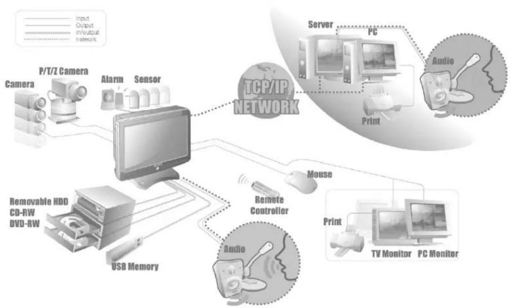
flowchart
graph TD
    A["Camera"] --> B["P/T/Z Camera"]
    B --> C["Alarm Sensor"]
    C --> D["TCP/IP NETWORK"]
    D --> E["Server PC"]
    E --> F["Print Audio"]
    D --> G["Mouse"]
    G --> H["Remote Controller"]
    H --> I["Audio Monitor"]
    I --> J["TV Monitor PC Monitor"]
    K["Removable HDD CD-RW DVD-RW"] --> L["USB Memory"]
    style A fill:#f9f,stroke:#333
    style B fill:#ccf,stroke:#333
    style C fill:#cfc,stroke:#333
    style D fill:#fcc,stroke:#333
    style E fill:#cff,stroke:#333
    style F fill:#ffc,stroke:#333
    style G fill:#cfc,stroke:#333
    style H fill:#fcc,stroke:#333
    style I fill:#cfc,stroke:#333
    style J fill:#ffc,stroke:#333
    style K fill:#cfc,stroke:#333

CLOVER
ELECTRONICS U.S.A.
Copyright © 2009 Clover Electronics U.S.A. All Rights Reserved.
CONTENTS
ABOUT THIS MANUAL....9
- UNPACKING.... 11
1-1. 26" WIDE LCD PANEL BUILT-IN 16 CH DIGITAL VIDEO RECORDER 12
2 FEATURES....13
3.WHAT TO DO AT THE TIME OF INSTALLATION.... 15
4.SPECIFICATIONS....17
5.INSTALLATION....19
5-1. CONTROLS AND CONNECTORS....20
5-2. NOTE FOR INSTALLATION 23
5-3. SYSTEM CONNECTION 24
5-4. INSTALLATION 25
5-4.1. Camera Connection....25
5-4.2. Installation of the Monitor 25
5-4.2.1. Connection of Composite Monitor 26
5-4.3. Sensor Connection and RELAY IN &OUT 26
5-4.4.RS485Connection 27
5-4.5 Connection to an Ethernet Network (Optional)....27
5-4.6. POWER CABLE CONNECTION 28
6. HOW TO OPERATE 29
6-1. GENERAL INFORMATION 31
6-2. OPERATING INTERFACE 32
6-3. IR REMOTE CONTROLLER 33
6-9.1. Manual (Continuous) recording ....56
6-9.2. Manual Event Recording....56
6-9.3. Timer Recording....57
6-9.4. Timer Event Recording ....58
6-9.5 Audio Recording....59
6-9.6. Estimated Recording Time....59
6-9.7. Recording Icons ....60
6-10. REPLAY 61
6-10.1. QUICK REPLAY....61
6-10.2. REPLAY 61
6-10.2.1. Playback Devices....62
6-10.2.2. Set the Start Time ....62
6-10.2.3. Replaying 64
6-10.2.4. Disappearance of Replay control buttons 66
Contents
6-11. COPY 68
6-11.1. Copying devices....68
6-11.2. Set the Copy Start Time (Copying extent)....69
6-11.3. Set the Copy End Time (Copying extent) 71
6-11.4. Copying the recorded data during replaying....72
6-11.5. PLAYER / AVI File Format....74
- SETUP.... 75
7-1. SETUP 78
7-2. SYSTEM 79
7-2.1. SYSTEM NAME 80
7-2.2. LANGUAGE....81
7-2.3. TIME / DATE 81
7-2.4. SYSTEM CONFIG 83
7-2.4.1. FACTORY DEFAULT 84
7-2.4.2. LOAD CONFIG / BACKUP CONFIG 85
7-2.5. PASSWORD....87
7-2.6. IR REMOTE ID....88
7-2.7. FIRMWARE UPDATE 89
7-2.8. SYSTEM INFO....89
7-3. DISK MANAGER 90
7-3.1. HDD WRITE FAIL 91
7-3.2. HDD OVERWRITE....91
7-3.3. Format 91
7-4. CAMERA....92
7-4.1. Camera ON/OFF....93
7-4.2. Camera Name (Camera Title)....93
7-4.3.Buzzer 94
7-4.4. Relay 94
7-4.5. Pan/Tilt Settings 95
7-4.6 Display....99
7-4.7 Sequencing dwell time 99
7-5. AUDIO 100
7-5.1. Microphone Volume .... 100
7-6. RECORD.... 101
7-6.1. Record ICON Display....101
7-6.2. All Manual / Timer recording button....102
7-6.3. All Motion ON / OFF, Sensitivity Setting 103
7-6.4. All Sensors ON / OFF 104
7-6.5. Size (Recording Resolution)....104
7-6.6. Recording Speed....105
7-6.7. Recording Quality....106
7-6.8. Recording Mode....107
7-6.8.1. Manual Recording....107
7-6.8.2. Manual Event Recording 107
7-6.8.3. Timer Recording (Schedule Recording) 107
7-6.8.4. Timer Event Recording 107
7-6.9. Recording by Motion Detection....108
7-6.10. Recording by Sensor (PIR Sensor) 117
7-7. NETWORK....119
7-7.1. IP Mode 119
7-7.2. GATEWAY, SUBNET, IP ADDRESS 120
7-7.3. Port 121
7-7.3.1 Port Forwarding 121
7-7.4. MAC ID....121
7-7.5. MNS (MAC NAME SERVER) 122
7-7.6. DDNS (DYNAMIC DOMAIN NAME SYSTEM)....123
7-7.7. HOW TO SETUP AND USE THE DDNS....125
7-7.7.1. Router....125
7-7.7.2. Registration to the DDNS server 125
7-7.8. EMAIL NOTIFICATION....126
8.REMOTE HOST PROGRAM 131
8-1. REMOTE PROGRAM OVERVIEW.... 133
8-2. INSTALLING THE PROGRAM TO PC.... 134
8-3. INTERNET EXPLORER.... 135
8-4. REMOTE HOST 137
8-4.1. Setup 139
Contents
8-4.2. Connection 142
8-4.3. Capture....143
8-4.4. Status 144
8-4.5.Replay 145
8-4.6. COPY 147
8-4.7. Switch the Normal Screen to Full Screen....149
8-4.8. Speaker / Microphone 150
8-4.9. Connection mode....151
8-4.9.1. Terminal mode....151
8-4.9.2. Multi mode....152
8-4.10. Copy in the Terminal mode....153
8-4.11 E-Map 155
8-4.11.1. Addition of map 155
8-4.11.2. Placement of cameras on the map 156
8-4.11.3. Usage of camera position 157
8-4.11.4. Deletion of Camera position icon 157
8-4.12 Pan / Tilt & Preset 158
8-5. PLAYER 159
APPENDIX....167
This is the Instruction Manual for 26" Wide TFT-LCD monitor built-in 16Ch DVR system, Model LCD26164, LCD26168 and LCD261616.
The last digit(s) of the model numbers (e.g.: 4, 8 and 16) represent the number of cameras included in the system.
This Manual describes how to install and operate the 26" Wide TFT-LCD monitor built-in 16Ch DVR system and provides specifications and features.
Please read this manual thoroughly and follow the installation process before using the system.

Note : Be sure to correctly follow step 3. What to do at the time of installation.
Contact our distributors or dealers when you have any queries.
1 Unpacking
Care should be taken when unpacking to avoid damaging the system.
Please check that the following items are included:

26" LCD Monitor built-in 16 Ch DVR
USB Mouse

AC Power Cable

2-Indoor camera with C-mount lens

Instruction Manual
2-Outdoor camera with mounting bracket

Host Program (DvrMaster) on CD

2-Mounting bracket for indoor cameras

RJ-45 Cable

4-6pin Din 60' cables

Warranty registration card
Remote Controller
Quick setup guide

2-Batteries

Mounting bracket hole cover

Note: Contact your dealer immediately if any components are missing.
1-1. 26" Wide LCD Panel Built-in 16 Ch Digital Video Recorder
LCD26164 is the most reliable and functional embedded DVR system available today. The system displays 16 channels of live images in Real Time speed, compresses data digitally and records them to the Hard Disk Drive, which can be replayed and searched easily any time.
The LCD26164 supports easy back up via USB port, external Hard Disk Drive and networking in both static & dynamic IP modes.
User can remotely view live images or search the recorded images.
Under emergency situation, the remote operator can control, turn on and turn off the field installed alarms, such as a siren or light.
It is a very user-friendly DVR system. User can control the LCD26164 by Mouse or Buttons on the side panel or Remote controller.
2 Features
▶ 26" Wide Screen
- High resolution TFT-LCD 1,366(H) x 768(V), Contrast ratio 700:1, Response time 8 msec
▶ Multi Functional Record
- Powerful, multiple Record Modes available: Manual (Continuous), Timer, and Motion Detection Recording.
▶ User friendly GUI
- A few simple buttons for Easy control.
▶ Automatic System Recovery
- Automatic and Complete System recovery within 10 seconds.
▶ Easy PTZ control via RS port
- No need to use PTZ controller
- PTZ control from remote PC
▶ Networking
- DHCP based automatic network set-up-Easy Network Configuration from Dynamic IP to Dynamic IP
- Support TCP/IP and Remote Control on all DVR features
- Up to 10 users can remote access the system through DVRMaster (GUI) or Internet Explorer simultaneously.
- DDNS support
▶ MPEG-4 Algorithm Compression
-The most advanced compression available today.
▶ High Resolution DVR 720 x 480
- Real time display 480 Frames/sec
- Recording speed 480 Frames/sec based on 360x240
- Programmable display resolution and recording speed on each channel
▶ 2 Way Audio
- Communicate between the system and cameras or between the system and client computer through the internet
▶ Easy Data Playback in any PC
- Back Up data convertible to AVI file format.
▶ Back UP
- External HDD, Stick memory, and through network access.
▶ Desktop or Wall-mountable
3 What to do at the time of Installation
The system should be installed in the following order;
-
Make sure all the required hardware is available.
-
26" wide TFT-LCD monitor built-in 16 Ch DVR
-Up to 16 cameras capacity (Refer to the retail box for the number of camera included in the system). - CCTV monitor or TV set if necessary
-
Network cable if connecting to a PC
-
Connect the cameras to the monitor (Refer to Fig 5-3).
- Confirm if live video is displayed on the monitor before going to the next step.
- Select the Setup Menu and set current date and time (Refer to Section 7-2.3).
- Run the FACTORY DEFAULT setting in the SYSTEM menu.
- Perform HDD formatting.
- Escape from Setup Menu.
- Set values for required options.
- Network cable should be connected to the monitor before turning the power on.
Refer to Fig 5-8 for the cable specification.
4 Specifications
| ITEM | DESCRIPTIONS | ||
| VIDEO SIGNAL | Television System NTSC PAL | ||
| Refresh Rate 60 fields/sec 50 fields | sec | ||
| Video Resolution 720x480 720x576 | |||
| Video Inputs 8-6pin Din Cameras and 8-BNC Cameras | |||
| Video Input Signal Composite 1.0 Vp-p 75 Ohms | |||
| Video Output 1-Composite output | |||
| Video Output Signal Composite 1.0 Vp-p 75 Ohms | |||
| VIDEO FEATURES | Live | 480 Frames/sec display | 400 Frames/sec display |
| Zoom | 2 times digital | ||
| Sequence | Sequence display in Full size | ||
| Display Format | 1 screen(full), Quad pages split, 9 split pages, 16 split | ||
| Camera Video enhance | Brightness, Contrast control on each cameras | ||
| LCD Display enhance | Brightness, Contrast, saturation, 4:3 or 16;9 selectable | ||
| AUDIO FEATURES | G.723 | 8ch Input / 1ch Output | |
| RECORD | Recording Speed | 480 Frames/sec | 400 Frames/sec |
| Recording resolution | 720x480,720x240,360x240 (NTSC)720x576,720x288,360x288 (PAL) | ||
| Codec | Mpeg4 | ||
| Recording | Timer, Motion, Alarm, Manual individually set | ||
| Pre record | 0~30 sec | ||
| Material | SATA HDD(Auto overwrite) | ||
| SEARCH | Manual, Timer ,Motion, Alarm, Each Camera, All Camera | Fast x128 , Slow, Forward, Reverse, Frame by Frame | |
| BACKUP | External HDD, USB memory, through Network | Each Camera, ALL Cameras, Time range | |
| Recorded data lock | Data protection in overwrite HDD | Time range, Back up | |
| USER INTERFACE | GUI | RGB 24bit full color | |
| Operating interface | Mouse, Keypad, IR remote controller, Network | ||
| NETWORK | Ethernet 10/100M Auto | TCP/IP, DHCP, MNS server | |
| EMAIL NOTIFICATION | SMTP Server | Alarm, Motion, Record ON/OFF, Replay, HDD Fail, Video loss, Power Loss...etc | |
| PC Program | Remote viewer | Same as DVR monitor (Mouse or Key button) | |
| PC Player | External HDD, USB memory, Internal HDD (Replay, Convert, Copy, Print) | ||
| USB | USB 2.0 | for external DVD R/W, CD R/W, HDD, USB memory | |
| SERIAL | RS485 | 16 camera Pan/Tilt, Remote control | |
| ALARM | Alarm Inputs 8 Inputs | ||
| Alarm Outputs 1 Relay Output(1A max) | |||
| Alarm Latch up | 1~30 sec | ||
| Buzzer Out | On/Off | ||
| HDD | SATA | 750GB (Refer to the retail box) | |
| POWER | Input Voltage AC 110V/ 220V 50~60Hz (Free voltage) | ||
| Power consumption | Approx. 200W | ||
| CONNECTORS | Video Inputs 8-6pin DIN & 8 BNC | ||
| Video Output 1 RCA for slave monitor | |||
| Audio Output 1 RCA for Speaker | |||
| Alarm In/Out | Alarm In: 9pin terminal block, Alarm Out: 3pin terminal block | ||
| RS485 | 2pin terminal block | ||
| Ethernet | RJ45 | ||
| Mouse | USB mouse | ||
| MECHANICAL | Dimension(m/m) | 650(W)x450(H)x100(D),650(W)x490(H)x200(D):with mounting bracket | |
| Weight | Approx.27 Lbs | ||
| ENVIRONMENT | Operating Temperature | 0 ~ 60°C | |
| Humidity | 10 ~ 60% | ||
| LCD | Display 26" TFT LCD active matrix | ||
| Pixel Pitch 0.4215 mm | |||
| Active Display Area 575.76(H) x 323 | 71(V) mm | ||
| Display Colors 16.7M (Hi-FRC) | |||
| Display Mode Normally White | |||
| Pixel Arrangement RGB vertical stripe | |||
| Luminance of White 500 cd/m2 | |||
| Contrast Ratio 700 : 1 | |||
| Viewing Angle L/R/U/D 80 / 80 / 80 / | 80 degrees | ||
| Operating Temperature | 0°C ~ 60°C | ||
| Storage Temperature | -25°C ~ 60°C | ||
[Fig 4-1 Specifications]
Design and the specifications are subject to change without notice.
5
Installation
CONTENTS
5-1. CONTROLS AND CONNECTORS....20
5-2. NOTE FOR INSTALLATION 23
5-3. SYSTEM CONNECTION ......24
5-4. INSTALLATION....25
5-4.1. CAMERA CONNECTION....25
5-4.2. INSTALLATION OF THE MONITOR....25
5-4.2.1. CONNECTION OF COMPOSITE MONITOR 26
5-4.3. SENSOR CONNECTION AND RELAY IN &OUT 26
5-4.4. RS485 CONNECTION 27
5-4.5 CONNECTION TO AN ETHERNET NETWORK (OPTIONAL) 27
5-4.6. POWER CABLE CONNECTION ....28
5-1. Controls and Connectors
- Front


[Fig. 5-1 Front/Side View]
1. REC Key
- Press this key to start recording.
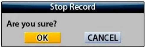
- In order to stop recording, press this key again or click the REC button on the MENU window and then the following message will be appeared. Click the OK button or press the ENTER key.
2. TALK Key
- See section 6-7.4.2 for information.
3. EXIT Key
- Press this key to exit menu without saving.
4. ENTER Key
- Press this key to select items or save menu settings.
5. UP Key
- Used to increase Audio Volume for the system.
6. DOWN Key
- Used to decrease Audio Volume for the system.
7. Stand-by Power Mode Button
- Turn the LCD Panel (Screen) On or Off
- Even though the LCD Screen is turned off by pressing this button, the system will be continued to work.
- See section 6-4 for more information.
8. POWER LED
- The red LED is lit when the Power switch on the rear of the system is ON.
9. Remote Control Signal Receiver
- Do not block the receiver port on the unit. Doing so may cause the remote controller to function improperly.
- Rear

5-2. Note for Installation
◆ Install the system according to the instructions described in this manual.
◆ The 26" LCD monitor built-in 16Ch DVR and Indoor Cameras are designed for indoor use and should not be used outdoors.
◆ Avoid any area with high humidity or dust which can shorten lifetime of the system.
- Choose a well ventilated area and keep minimum of 10" away from obstructions. Do not place the system near heat generating devices.
◆ Avoid any area with movement as this can interfere with the internal Hard Drive.
◆ Use a compatible input/output signal type of cameras and monitor.
◆ Contact your dealer if you have any problems in regards to the installation of this system.
The Warranty may be voided in case of unauthorized disassembling, abuse or modification.
5-3. System Connection

flowchart
graph TD
    A["Camera"] --> B["P/T/Z Camera"]
    B --> C["Alarm"]
    C --> D["Sensor"]
    D --> E["TCP/IP NETWORK"]
    E --> F["Server"]
    E --> G["PC"]
    E --> H["Print"]
    E --> I["Audio"]
    E --> J["Mouse"]
    E --> K["Remote Controller"]
    K --> L["USB Memory"]
    L --> M["Removable HDD CD-RW DVD-RW"]
    M --> N["Audio"]
[Fig 5-3 System Connection]
5-4. Installation
5-4.1. Camera Connection
- Connection of 6pin MINI DIN Cameras
Connect the supplied cameras to the Camera Input (6pin mini DIN jack) on the back of the system as shown in [Fig. 5-2 Rear View].
- Connection of BNC Cameras
Connect the BNC cameras (not included) to the Camera Input (BNC connector) on the back of the system as shown in [Fig. 5-2 Rear View].
5-4.2. Installation of the Monitor

natural_image
Close-up of a gray electronic device with two red arrows pointing to internal components, showing no visible text or symbols.[Fig. 5-4-1 Removing mounting bracket]

natural_image
Close-up of a gray electronic device casing with red arrows indicating internal components (no text or symbols visible)[Fig. 5-4-2 Cover the mounting bracket hole]
- Desktop
- Place the system on the flat surface.
- Do not place this product near a bathtub, kitchen sink, wet basement, over a radiator, or heat generator.
▪ Installation of the system on the wall
- Place the system on the flat surface with soft fabric as shown in Fig. 5-4-1.
- Separate the mounting bracket by removing three screws on the rear of the system as shown in Fig.5-4-1.
- Cover the mounting bracket hole with the provided lid as shown in Fig. 5-4-2.
- The wall mounting bracket is not included in the system and refer to the manufacturer's instructions on how to install it to the wall.

Note:
- Pay attention to not make scratches or dents on the surface of panel (screen) during installation of the system.
- In case of this, the warranty will be voided.
5-4.2.1. Connection of Composite Monitor
If necessary, connect the composite Video Output (yellow RCA) and Audio Output (white RCA) to Video IN and Audio IN on a composite monitor or TV (RCA cable: not included).
5-4.3. Sensor Connection and RELAY IN & OUT
- SENSOR Connection (SENSOR IN)
Connect up to 8 sensors to ALM (SENSOR) IN. The Sensors should be contactor type and support N.O. (Normal Open).

[Fig 5-5 Sensor In]
- ALARM OUT Connection
When necessary, use ALARM OUT. The ALARM OUTPUT is a relay contactor type and supports N.O. (Normal Open) and N.C. (Normal Close). The Output capacity is 220V 1A. A higher capacity can cause system failure.

[Fig 5-6 Alarm Output]
5-4.4. RS485 Connection
- Connect the cable to the "RS485 PORT" on the terminal block of the system. Refer to [Fig 5-7] for connection of Connector PIN
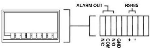
[Fig 5-7 RS485 Connection]
5-4.5 Connection to an Ethernet Network (Optional)
- Connecting the cable to Ethernet.
Our Ethernet connector is a RJ45 type. The maximum cable length is 300 ft. When you want to use a longer cable, we suggest using repeater.
Refer to [Fig. 5-8] for connector pin configuration.
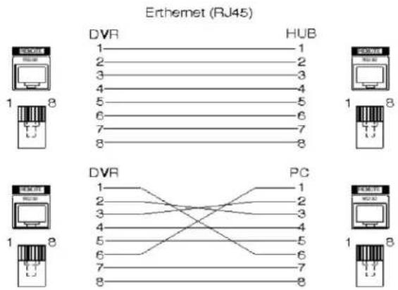
[Fig 5-8 Straight-through & Crossover Cable]
5-4.6. POWER CABLE CONNECTION
- Connect the provided AC power cable to the monitor and an AC outlet. AC input voltage is AC 110V to 220V 50/60Hz.
It should not be shared with other electrical equipment on the same line.
Frequent power cuts can cause crucial failures, so if you have an unstable power source we recommend the use of an Uninterrupted Power Supply or other backup power source.
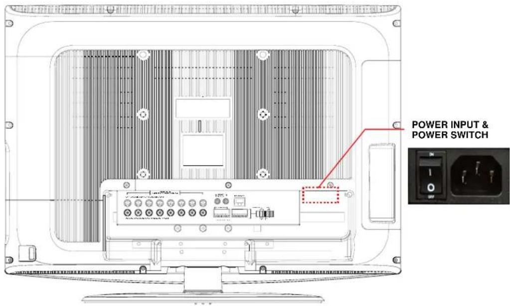
[Fig.5-9 Power cable connection]
6
How to operate
CONTENTS
6-1. GENERAL INFORMATION.... 31
6-2. OPERATING INTERFACE.... 32
6-3. IR REMOTE CONTROLLER 33
6-4. POWER ON/OFF 34
6-4.1. POWER ON 34
6-4.2. STAND-BY POWER MODE BUTTON 34
6-4.3. POWER OFF 34
6-5. MENU WINDOW 36
6-6. DISPLAY SCREEN.... 37
6-6.1. FULL SCREEN 37
6-6.2. SPLIT SCREENS.... 38
6-7. LIVE 39
6-7.1. FULL SCREEN 39
6-7.2.SPLIT SCREEN 39
6-7.3.SEQUENCING SCREENS 40
CONTENTS
6-7.4. LIVE AUDIO 41
6-7.4.1. COMMUNICATION BETWEEN MONITOR AND CLIENT COMPUTER VIA INTERNET .....42
6-7.4.2. COMMUNICATION BETWEEN MONITOR AND CAMERAS 42
6-7.5.ZOOM....43
6-7.6. OSD ON / OFF 44
6-7.7. PAN / TILT 45
6-7.8. SYSTEM STATUS....48
6-7.9. POWER LOSS LISTS 49
6-7.10. VIDEO LOSS LIST ....51
6-8. VIDEO ENHANCE ....53
6-8.1. CAMERA INPUT CONFIG (CONTRAST / BRIGHTNESS)....54
6-8.2. VGA OUTPUT CONFIG (SCALE / CONTRAST / BRIGHTNESS / SATURATION) .....55
6-9. RECORD....56
6-9.1. MANUAL (CONTINUOUS) RECORDING....56
6-9.2. MANUAL EVENT RECORDING....56
6-9.3. TIMER RECORDING 57
6-9.4. TIMER EVENT RECORDING....58
6-9.5 AUDIO RECORDING ....59
6-9.6. ESTIMATED RECORDING TIME 59
6-9.7. RECORDING ICONS....60
6-10. REPLAY 61
6-10.1. QUICK REPLAY....61
6-10.2. REPLAY 61
6-10.2.1.PLAYBACK DEVICES....62
6-10.2.2. SET THE START TIME....62
6-10.2.3. REPLAYING....64
6-10.2.4. DISAPPEARANCE OF REPLAY CONTROL BUTTONS....66
6-11. COPY 68
6-11.1.COPYING DEVICES....68
6-11.2. SET THE COPY START TIME (COPYING EXTENT)....69
6-11.3. SET THE COPY END TIME (COPYING EXTENT)....71
6-11.4. COPYING THE RECORDED DATA DURING REPLAYING....72
6-11.5.PLAYER/AVI FILE FORMAT 74
6-1. General Information
- You can operate all functions of the system by use of the buttons located on the side panel, remote controller and a mouse. Additionally, you can remotely control this unit via RS485 or the Ethernet port located on the back of the unit.
- System status is indicated by either LED lights on the operator buttons or the monitor.
- The system is protected from any accidental pressing of any operator buttons, but care should be taken when using the functions of HDD Formatting as this can lead to data loss.
6-2. Operating Interface
There are 3 ways to operate the system by pressing the buttons on the side panel or buttons on the remote controller and clicking the mouse. A lot of users mostly prefer to use a mouse on these kinds of products such as DVRs, computers and computer-aided devices. Therefore we would like to describe all the instructions in this manual based on using the mouse.
6-3. IR Remote Controller

[Fig.6-1 IR Remote Controller]
| 1. POWER / STANDBY |
| 2. REC |
| 3. STATUS |
| 4. ZOOM |
| 5. FREEZE |
| 6. No.1~16 Channel (Full Screen)or IR ID Number |
| 7. Display format (Split) |
| 8. IR ID Set |
| 9. MENU |
| 10. ESC |
| 11. UP |
| 12. DOWN |
| 13. LEFT |
| 14. RIGHT |
| 15. ENTER |
| 16. SEARCH / PLAY |
| 17. STOP |
| 18. FF, REW |
| 19. Movement forward or backwardby 1 Field. |
| 20. QUICK SEARCH |
| 21. PAN / TILT |
| 22. ZOOM / FOCUS |
| 23. FUNC |
6-4. Power On/Off
6-4.1. POWER ON
On the rear panel:
Turn on the POWER switch on the rear panel (See Fig.5-2). The LED on the front panel is lit when the POWER switch is ON.
By Stand-by Power Mode Button
Press this button on the side panel (See Fig.5-1) to turn ON the system when the POWER (MAIN) switch is turned ON and the Stand-by Power Mode Button is turned OFF.
6-4.2. STAND-BY POWER MODE BUTTON
In order to extend the lifetime of the LCD screen and the backlights inside the monitor, press the POWER button located on the side panel (See Fig.5-1) to turn OFF if you don't need to observe the system for a long time. The system will continue recording when it is in the recording mode even though the Stand-by Power Mode Button is turned OFF.
6-4.3. POWER OFF
By pressing the Stand-by Power Mode Button:
Press the POWER button on the side panel for 3 seconds and then the POWER OFF message as shown in [Fig.6-2] will be displayed on the screen.
= Click the OK button to turn the power OFF.
On the remote controller:
Press the POWER button on the remote controller and then the following message will be displayed on the screen.

[Fig.6-2 Message of P O WREoff]
- Press the ENTER (←) button to turn the power OFF.
By clicking the mouse:
- Right-click on the screen in the live mode to display the MENU window.
- Click the POWER OFF button on the MENU window (See Fig.6-3) and then the message (See Fig.6-2) will be displayed on the screen.
- Click the OK button to turn the power off.
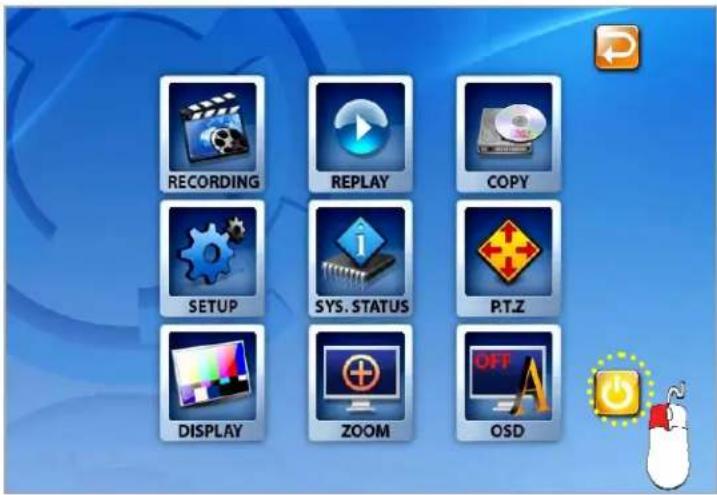
[Fig.6-3 POWER button on MENU window]
6-5. Menu Window
Right-click on the screen in the LIVE or the RECORD mode and then the MENU window will
be appeared as shown in Fig. 6-4. Click the

(EXIT) button to return to the LIVE Mode.

natural_image
Collage of 16 diverse indoor and outdoor scenes including a casino market, retail, and event hall (no visible text or symbols)
[Fig.6-4 Menu Window]
6-6. Display Screen
6-6.1. FULL SCREEN
![SEQUENCE ICON RECORD ICON CAMERA TITLE E COPY ICON AUDIO ICON CAM 06 VIDEO LOSS 2009/02/03 19:38:04 LIVE AUDIO CURRENT TIME [Fig.6-5 FULL screen]](/content/2026/05/1084259/images/de210c61ea48bdb7e00471f507bed1edd28c9c660968092ff948eed0bb6c7fd6.jpg)
6-6.2. SPLIT SCREENS

FULL SCREEN

SEQUENCING SCREEN

QUAD SCREEN

4page SEQUENCING SCREEN

9 SPLIT SCREEN

2page SEQUENCING SCREEN
| 1 | 2 | 3 | 4 |
| 5 | 6 | 7 | 8 |
| 9 | 10 | 11 | 12 |
| 13 | 15 | 14 | 16 |
16 SPLIT SCREEN
6-7. LIVE
6-7.1. FULL SCREEN
- A Full SCREEN is available in the LIVE mode or the RECORD mode.
- Click on a certain camera's screen in the LIVE mode or in the RECORD mode, then a FULL SCREEN will be displayed.
- Click the FULL screen to return to the SPLIT SCREEN.
6-7.2. SPLIT SCREEN
A SPLIT SCREEN is available in the LIVE mode or the RECORD mode.
- Scroll up or down the mouse wheel in the LIVE mode, then the SPLIT SCREENS pop-up screen will be displayed as shown in Fig. 6-6.
To display, click one of the SPLIT screens on the pop-up screen within 30 seconds. It will disappear after that time.

[Fig.6-6 SPLIT SCREENS pop-up screen]
6-7.3. SEQUENCING SCREENS
natural_image
Abstract diagram of stacked squares with an orange arrow and dotted line, no text or symbols present- Displaying the cameras in SEQUENCE is available in the LIVE mode or the RECORD mode.
Each of the channels will be displayed in sequence and the dwell time can be adjusted in the camera set up menu (Refer to 7-4.7).
This ICON is displayed in the upper left hand corner of the screen while the system is in the Sequencing Mode.
- Scroll up or down the mouse wheel in the LIVE mode, then click a 📄 (SEQUENCE) button on the SPLIT SCREENS pop-up screen as shown in Fig.6-7.
- Click a Full screen to return to the SPLIT screen while the system is sequencing.

: Full Screen Sequencing

: 4 Split Screen Sequencing

: 9 Split Screen Sequencing

[Fig.6-7 SPLIT SCREENS]

[Fig.6-8 SEQUENCING screen]
6-7.4. LIVE AUDIO
- Setup LIVE AUDIO when the system is not connected through the DvrMaster or Internet Explorer and the OSD is turned ON.
- If cameras (up to 16 cameras) have audio function, it will sound in the live mode.
- Click the 📄 (LIVE AUDIO) button in the LIVE mode (See Fig.6-9), then the LIVE AUDIO popup screen will be displayed (See Fig.6-10).
- Click the CHANNEL button you wish to listen on the LIVE AUDIO popup screen as shown below (See Fig.6-10). The pop up screen will disappear after 10 seconds.
- Turn the AUDIO (speaker) ON by clicking the AUDIO ON/OFF button as shown below (See Fig.6-10). You can select the AUDIO ON or OFF by repeatedly clicking the mouse.
AUDIO ON: 📋, AUDIO OFF: ✉ - Adjust the Audio Volume by clicking the + or the ▼ button when the AUDIO is turned ON.
- Click the ⬆ (EXIT) button to return to the LIVE Mode.

[Fig.6-9 LIVE AUDIO button]

AUDIO ON/OFF
VOLUME Control

[Fig.6-10 LIVE AUDIO popup screen]
EXIT
CHANNEL
6-7.4.1. COMMUNICATION BETWEEN MONITOR AND CLIENT COMPUTER VIA INTERNET
This system is normally in listening mode between the LCD monitor and your computer through the Internet (DvrMaster or Internet Explorer). In order to communicate between the system and your computer, connect a head phone or a microphone and a speaker to the computer. Adjust the Speaker and the Microphone volume on the DvrMaster or Internet Explorer by clicking the amount of volume (See section 8-4.8 Speaker / Microphone).
- Don't forget to turn the AUDIO (speaker) ON by clicking the SPEAKER icon (See section 6-7.4 for more information) on the system.
6-7.4.2. COMMUNICATION BETWEEN MONITOR AND CAMERAS
- Turn the AUDIO (speaker) ON by clicking the SPEAKER icon on the LIVE AUDIO pop up screen. (See 6-7.4 for more information).
To communicate (two way Audio) with a camera, select one out of Indoor cameras by clicking the CHANNEL button on the LIVE AUDIO pop up screen and press the TALK button on the side of the system.
To listen only (one way Audio), select one out of outdoor/outdoor cameras by clicking the CHANNEL button on the LIVE AUDIO pop up screen.

Note:
- It is impossible to communicate between the system and the cameras as long as the DVRMaster (GUI) is being executed, even though the Speaker and the Microphone are turned Off.
- Exit the DVRMaster by clicking the Exit button on the GUI in order to communicate between the system and the cameras.
- In order to listen to the recorded audio in playback mode, select the corresponding channel to make it a full screen.

6-7.5. ZOOM
The image on the screen will be zoomed up to 2 times when the ZOOM button is clicked in the LIVE mode (This function is available on the full screen mode only).
- Right-click on the screen in the LIVE or the RECORD mode and the MENU window will be appeared as shown in Fig. 6-4.
- Click the ZOOM button on the MENU window screen.
- Move the mouse on the ZOOMED screen, and the 8-directional arrow marks will be appeared as shown below (Fig.6-11).
- Click the (EXIT) button to return to the MENU window.

[Fig.6-11 ZOOMED screen]

6-7.6. OSD ON / OFF
OSD ON /OFF is possible in the LIVE mode or RECORD mode.
- Click the OSD button on the MENU window to turn the OSD (On Screen Display) ON or OFF. When the OSD is in OFF position, all the texts on the screen will be disappeared.

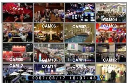
[Fig.6-12 OSD ON SCREEN]

natural_image
Collage of 20 diverse indoor and outdoor trade events including hotels, retail stalls, and crowds (no visible text or signage)[Fig.6-13 OSD OFF SCREEN]

6-7.7. PAN / TILT
- Click the PAN/TILT button on the MENU window in the LIVE mode to access the PAN/TILT cameras.
- Click the ✗ (EXIT) button to return to the MENU window.

[Fig.6-14 PAN/TILT button]

[Fig.6-15 PAN/TILT window]

[Fig.6-16 PAN/TILT CONTROL]
▪ Channel Selection and Screen Conversion
To change a channel, press the CHANNEL button on the remote controller or click the CHANNEL button on the [Fig.6-16 PAN / TILT CONTROL window]. It will be converted a full screen. To return to the MENU window, click the (EXIT) button as shown in Fig.6-16.
- ZOOM / FOCUS
Control the ZOOM and FOCUS of PAN/TILT camera.
Click the ZOOM/FOCUS button on the PAN/TILT CONTROL window [Fig.6-16 PAN / TILT CONTROL window].
- PAN / TILT
Control the PAN and TILT of PAN/TILT camera.
Click the PAN/TILT Button on the PAN/TILT CONTROL window [Fig.6-16 PAN / TILT CONTROL window].
• IRIS
To provide optimum performance, adjust the lens iris by clicking "+" or "-" in Fig.6-16.
- Button of PAN/TILT Control window


Move the PAN/TILT window as shown in Fig.6-16 by clicking the Left or Right button if necessary.
PRESET

[Fig.6-16-1 Preset Menu]
It is a function to preset the PTZ camera(s) which you wish to monitor frequently.
Preset Setup
- Select a position of camera you wish to preset and click the SET button in Fig.6-16-1.
- Click the number(s) for the current position of camera.
- Delete the numbers by using ← button.
Preset Execution
Click the number(s) which you preset and click GO button to move the camera.
* If you preset the number again, the previous setup is not available and only current setup is available.
6-7.8. SYSTEM STATUS
- Click the SYSTEM STATUS button on the MENU window to see the system status as shown below (Fig.6-17).
- Click the (EXIT) button to return to the MENU window.
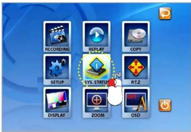
[Fig.6-17 SYSTEM STATUS button]

[Fig.6-18 SYSTEM STATUS window]
6-7.9. POWER LOSS LISTS
The list indicates the time/date when the system power is turned OFF.
- Click the POWER LOSS LISTS button on the SYSTEM STATUS window to view the POWER LOSS LISTS.
Each of the pages contains 10 lists. You can search the pages by clicking the UP/DOWN button.
- Click the (EXIT) button to return to the SYSTEM STATUS window.

[Fig.6-19 POWER LOSS LISTS window]
- CLEAR LISTS button
Click the CLEAR LISTS button to clear the lists, you will be prompted to confirm changes.
When you click the OK button, the POWER LOSS LISTS will be deleted.
To cancel, click the CANCEL button

[Fig.6-20 POWER LOSS LISTS Message]
6-7.10. VIDEO LOSS LIST
The list indicates the video loss channel and the time/date when the video signal is disconnected.
- Click the VIDEO LOSS LISTS button on the SYSTEM STATUS window to view the VIDEO LOSS LISTS.
- Each of the pages contains 4 lists. You can search the pages by clicking the UP/DOWN button.
- Click the (EXIT) button to return to the SYSTEM STATUS window.

[Fig.6-21 VIDEO LOSS LISTS window]

[Fig.6-22 VIDEO LOSS window]
- CLEAR LISTS button
Click the CLEAR LISTS button to clear the lists, you will be prompted to confirm changes.
When you click the OK button, the VIDEO LOSS LISTS will be deleted.
To cancel, click the CANCEL button

[Fig.6-23 VIDEO LOSS LISTS Message window]
6-8. VIDEO ENHANCE
- Click the DISPLAY button in the MENU window to enhance the picture quality on each of channels (Contrast and Brightness) and VGA output (Contrast, Brightness and Saturation). The VIDEO ENHANCE menu will show up (See Fig.6-25).
- Click the (EXIT) button to return to the MENU window.
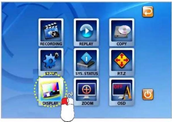
[Fig.6-24 DISPLAY button]

[Fig.6-25 VIDEO ENHANCE window]
6-8.1. CAMERA INPUT CONFIG (CONTRAST / BRIGHTNESS)
- Click a CAMERA INPUT button in the VIDEO ENHANCE menu.
- The CONTRAST and BRIGHTNESS sliders will be displayed along with camera picture as shown in Fig.6-26.
- Adjust the Contrast and Brightness with the sliders by clicking the mouse.
- To return to the VIDEO ENHANCE menu, click the (EXIT) button.

[Fig.6-26 CAMERA INPUT]
6-8.2. VGA OUTPUT CONFIG (SCALE / CONTRAST / BRIGHTNESS / SATURATION)
To Setup the SCALE / CONTRAST / BRIGHTNESS / SATURATION of VGA Output, click the VGA OUTPUT in the VIDEO ENHANCE menu and then the VGA ENHANCE menu will display as shown in Fig.6-27.
- Select one of Scales (Aspect Ratio) between 16:9 and 4:3 by clicking the box. The default value is 16:9.
- Adjust the Contrast, Brightness and Saturation by using the sliders or clicking the slider bars.
To Return to the VIDEO Enhance menu, click the (EXIT) button on the VGA ENHANCE menu.

[Fig. 6-27 VGA ENHANCE menu]
6-9. Record

This system provides Watchdog function.
When power goes off during recording and the power turns on, the system will automatically start recording.
6-9.1. Manual (Continuous) recording
- Click the SETUP icon on the MENU window in the LIVE mode.
" Click the RECORD button in the SETUP menu and the RECORD window will be displayed. - Select the MANUAL RECORDING ( ) between the MANUAL RECORDING ( ) and the TIMER RECORDING ( ) as shown in Fig.6-28. All channels can be set at the same time by clicking the ALL (ALL) or each of the channels can be set by clicking the MANUAL RECORDING ( ) on the CAM 1 through CAM 16.
The MOTION (☐) and SENSOR (☐) as shown in Fig.6-28 should be turned OFF in this recording mode.
- Press the RECORD button on the side panel or click the RECORD icon on the MENU window.

[Fig.6-28 Manual Recording]
6-9.2. Manual Event Recording
- Click the SETUP icon on the MENU window in the LIVE mode.
- Click the RECORD button in the SETUP menu and the RECORD window will be displayed.
- Select the MANUAL RECORDING ( ) between the MANUAL RECORDING ( ) and the TIMER RECORDING ( ) as shown in Fig.6-29. All channels can be set at the same time by clicking the ALL (ALL) or each of the channels can be set by clicking the MANUAL RECORDING ( ) on the CAM 1 through CAM 16.
The MOTION (☐) or SENSOR (☐) as shown in Fig.6-29 should be turned ON in this recording mode.
- Press the RECORD button on the side panel or click the RECORD icon on the MENU window.

[Fig.6-29 Manual Event Recording]
6-9.3. Timer Recording
- Click the SETUP icon on the MENU window in the LIVE mode.
- Click the RECORD button in the SETUP menu and the RECORD window will be displayed.
- Select the TIMER RECORDING (☐) between the MANUAL RECORDING (☐) and the TIMER RECORDING (☐) as shown in Fig.6-30. All channels can be set at the same time by clicking the ALL (ALL ☐) or each of the channels can be set by clicking the TIMER RECORDING (☐) on the CAM 1 through CAM 16.
The MOTION (☐) and SENSOR (☐) as shown in Fig.6-30 should be turned OFF in this recording mode.
- Choose one from SUNDAY to SATURDAY in the TIMER menu by clicking the mouse on (X) that turns to (O). You can choose the value O or X by repeatedly clicking the mouse.
- Click the Hour (or Minute) button in Fig.6-32 to setup the Starting Time and Ending Time, then the Hour (or Minute) table will appear as shown in Fig.6-33.
-Click the Hour (or Minute) you wish to set up.
-The recording time can be set in military hour mode (24hour).
- Press the RECORD button on the side panel or click the RECORD icon on the MENU window.

[Fig.6-30 Timer Recording setup]
6-9.4. Timer Event Recording
- Click the SETUP icon on the MENU window in the LIVE mode.
- Click the RECORD button in the SETUP menu and the RECORD window will be displayed.
-
Select the TIMER RECORDING (☐) between the MANUAL RECORDING (☐) and the TIMER RECORDING (☐) as shown in Fig.6-31. All channels can be set at the same time by clicking the ALL (ALL ☐) or each of the channels can be set by clicking the TIMER RECORDING (☐) on the CAM 1 through CAM 16.
The MOTION (☐) or SENSOR (☐) as shown in Fig.6-31 should be turned ON in this recording mode. -
Choose one from SUNDAY to SATURDAY in the TIMER menu by clicking the mouse on (X) that turns to (O). You can choose the value O or X by repeatedly clicking the mouse.
- Click the Hour (or Minute) button in Fig.6-32 to setup the Starting Time and Ending Time, then the Hour (or Minute) table will appear as shown in Fig.6-33.
-Click the Hour (or Minute) you wish to set up.
-The recording time can be set in military hour mode (24hour).
- Press the RECORD button on the side panel or click the RECORD icon on the MENU
window.

[Fig.6-31 Timer Event Recording]

[Fig.6-32 Timer Menu]
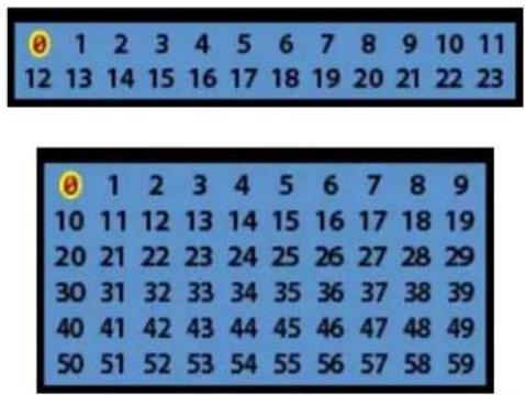
[Fig.6-33 Hour/Minute Selection Table]
6-9.5 Audio Recording
- Click the Audio Recording button, O or X in the RECORD menu as shown in Fig.6-34. If the "O" is selected, the corresponding channel's audio will record along with video signals. If the "X" is selected, the corresponding channel's audio won't record but video signals will record continuously.
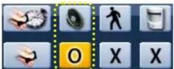
[Fig.6-34 Audio Record ON/OFF button]
6-9.6. Estimated Recording Time
- Displays the estimated recording duration according to the current recording setup.
▪ The estimated recording time displays in the Manual (Continuous) recording mode only.

[Fig.6-35 Estimated Recording Time]
6-9.7. Recording Icons
The Recording Icons depends on recording modes are displayed in the upper left hand corner of the screen.
- To turn the Recording Icon OFF, click the DISPLAY ON in the RECORD menu and then it will be turned OFF. You can select the value ON or OFF by repeatedly clicking the mouse.

[Fig.6-36 Recording Icons]
6-10. REPLAY
6-10.1. QUICK REPLAY
It is available only by pressing the QICK SEARCH button on the remote controller.
- Press the PLAY button, and the recent recorded list will be played.
6-10.2. REPLAY

- Click the REPLAY icon on the MENU window, then the REPLAY window as shown in Fig.6-37 will be displayed.
- Click the (EXIT) button to return to the previous mode.

[Fig.6-37 REPLAY window]
6-10.2.1. Playback Devices
In order to payback, plug the USB devices such as external USB HDD, USB memory to the USB port or insert a recorded media (CD-R/W or DVD-R/W) into the DVD-R/W drive.
When the devices are ready to playback, the Ready on the corresponding devices will be displayed as shown in Fig.6-38.
Click the mouse on a device among HDD, USB, CD-R/W and DVD-R/W that is displaying the Ready (See Fig.6-38). The corresponding light will be lit in yellow when the device is selected.
![HDD USB CD-RW DVD-RW READY HDD USB CD DVD [Fig.6-38 REPLAY DEVICE button]](/content/2026/05/1084259/images/f0b20688bf97e8294afcbdbc1530b8729c7b71934c2288bf24d72a4955b7b4f5.jpg)
6-10.2.2. Set the Start Time
- Select the Date (year / month / day) on the calendar by clicking the mouse on the highlighted character in black that turns to highlighted character in red (See Fig.6-39).
The highlighted character in black indicates the dates and times that recorded data exists, and the highlighted character in red indicates the selected dates and times. - Select the month (year) by clicking the mouse on the ◀button or ▶button.

[Fig.6-39 Calendar window]
- Select the hour on the Start Time Select Window (See Fig.6-40) by clicking the mouse on the Hour (0 – 23 hour) you wish to start to play.
The green active buttons indicate the HOUR that recorded data exists, and the red active buttons indicate the selected Start HOUR.

[Fig.6-40 Start Time Select window]
By using the Replay Time set-up buttons:
The time and date can also set on the Replay Time set-up button window (See Fig.6-41).
- Click the Month/Date/Year button as shown in Fig.6-41, and then select the
Month/Date/Year in the displaying calendar by clicking ◀ or ▶ button for a month, year and a date.
- Click the Hour (or Minute/Second) button in Fig.6-41, and then the Hour (or Minute/Second) table will appear as shown in Fig.6-33.
- Click the Hour (or Minute/Second) you wish to set up.

[Fig.6-41 Replay time set-up button]
By using the Replay Time set-up bar:
The starting time to play can also be set by clicking the slider on the bar and dragging it or clicking the bar.

[Fig.6-42Replay time set-up bar]
6-10.2.3. Replaying
Replaying start time set-up can be possible within a recording time extent.
▪ Replay buttons (NORMAL / MOTION / SENSOR)

NORMAL PLAY: Click the button to play all the recorded data.

MOTION PLAY: Click the button to play the recorded data by MOTION only.

SENSOR PLAY: Click the button to play the recorded data by SENSOR only.
- How to control the buttons while replaying
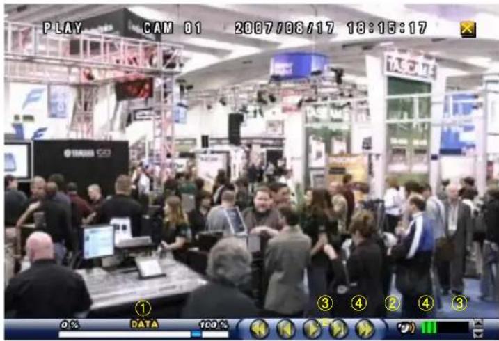
[Fig.6-43 Replay screen]
① Search Slider
It is possible to playback by clicking the slider on the bar and dragging it.
② PLAY / PAUSE
Click the

button to pause.

button to replay when in the pause mode.
Click the
③ REW/FF
During replaying, press the forwarding up to 128 times.

or button for fast rewinding and fast


Keep pressing the
(Same as shuttle ring)
④ PREV / NEXT
During replaying, press the

button to view previous frame in still image and press
the
button to view the next frame in still image.
⑤ Speaker ON / OFF
Turn speaker ON or OFF
⑥ Speaker Volume
Adjust the Audio Volume by clicking the ▲ or the ▼ button when the AUDIO is turned ON.
6-10.2.4. Disappearance of Replay control buttons
During replaying, the replay control buttons appear on the bottom of the screen. To disappear, drag the mouse pointer downward until the replay control buttons disappear and to appear, drag the mouse pointer upward until the replay control buttons appear.
- Click the mouse on one out of channels during replaying to view a full screen.
- Click the mouse on the full screen during replaying to return to the split screen.

natural_image
Collage of 16 photos showing various retail scenes including shops, stores, and booths, with no visible text or symbols.[Fig.6-44 SPLIT screen during replaying]

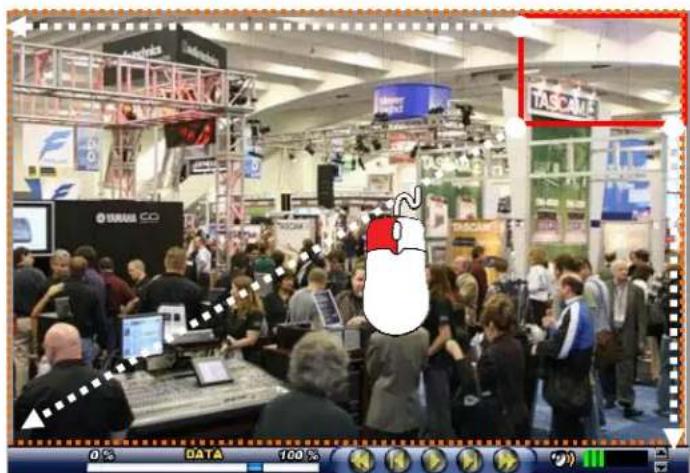
[Fig.6-45 FULL screen during replaying]
6-11. COPY

- Click the COPY icon on the MENU window, and the COPY window as shown in Fig.6-46 will be displayed.
- Click the (EXIT) button to return to the previous mode.

[Fig.6-46 COPY window]
6-11.1. Copying devices
In order to copy the recorded data, plug the USB devices such as external USB HDD, USB memory to the USB port or insert a blank media (CD-R/W or DVD-R/W) into the DVD-R/W drive.
When the device and media are ready to copy, the Ready on the corresponding device and media will be displayed as shown in Fig.6-46.
We recommend you to format the USB devices prior to copy the recorded data as follows, but the Medias such as CD-R/W and DVD-R/W don't need to format.
- Connect the USB devices to the DVR
- Click the SETUP icon on the MENU window, and the SETUP menu will be displayed.
- Click the DISK MANAGER in the SETUP menu, and the DISK MENAGER will be displayed.
- Click the mouse on the USB button in the DISK MANAGER, and you will be asked.
- Click the OK, and then the progressive bar will be shown along with FORMATTING USB....
In regards to blank Medias (CD-R/W and DVD-R/W)
Most Medias can be used with the system, but some of them may be not compatible with. Refer to the included instructions related to Medias or visit the website of DVD/CD DRIVE unit manufacturer for more information.
6-11.2. Set the Copy Start Time (Copying extent)
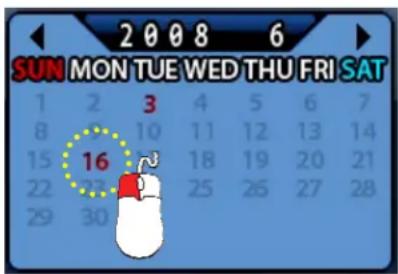
- Select the Date (year / month / day) on the calendar by clicking the mouse on the highlighted character in red that turns to highlighted character in black (See Fig.6-47).
The highlighted character in black indicates the dates and times that recorded data exists, and the highlighted character in red indicates the selected dates and times.
- Select the month (year) by clicking the mouse on the ◀button or ▶button.
- Select the hour on the Copy Start Time and Channel Selection Window (See Fig.6-48) by clicking the mouse on the Hour (0 – 23 hour) you wish to start to copy.
The green active buttons indicate the HOUR that recorded data exists, and the red active buttons indicate the selected Start HOUR.
[Fig.6-47 Calendar for Copying]

[Fig.6-48 Copy Start time and Channel Selection window]
① All channels, HOUR selection button.
Click the arrow button in the upper left corner as shown in Fig.6-48 to set the full extent of the recording and all the channels simultaneously.
② HOUR selection button
Select the start time to copy by clicking the mouse on HOUR (0-23: in the military hour). Thereafter the extent of the recording will be saved on.
③ Channel selection button
Some channels can be selected by clicking the mouse on the corresponding channels.
By using the Copy Start/End set-up buttons:
The time and date can also set on the Copy Start/End set-up buttons window (See Fig.6-49).
- Select the values (year/month/date and hour/minute/second) by clicking the mouse, change the values with the mouse's wheel and click the mouse again on the changed values to complete as shown in Fig.6-49.

[Fig.6-49 Copy Start/End setup buttons]
By using the Start/End set-up bar:
The starting time to copy can also be set by clicking the slider on the bar and dragging it or just click the bar.

[Fig.7-50 Copy Start/End setup bar]
6-11.3. Set the Copy End Time (Copying extent)
Refer to the above explanation (See section 6.11.2.).
6-11.4. Copying the recorded data during replaying
The system, LCD26164 allows users to copy the recorded data during replaying.
- Start replaying (See section 6-10).
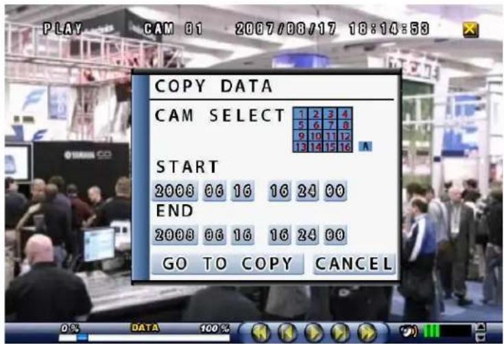
Right-click on the replaying screen, then the COPY DATA screen will be displayed (See Fig.6-51).
To set the starting time and date to copy, select the values (year/month/date window and hour/minute/second) on the COPY DATA window by clicking the mouse, change the values with the mouse's wheel and click the mouse again on the changed values to complete. - Select each of channels (1 through 16 in red) or "A" in black for all the channels on the COPY DATA window, and click on the SELECTED button to save.
[Fig.6-51 Start Copy Time Setup window]
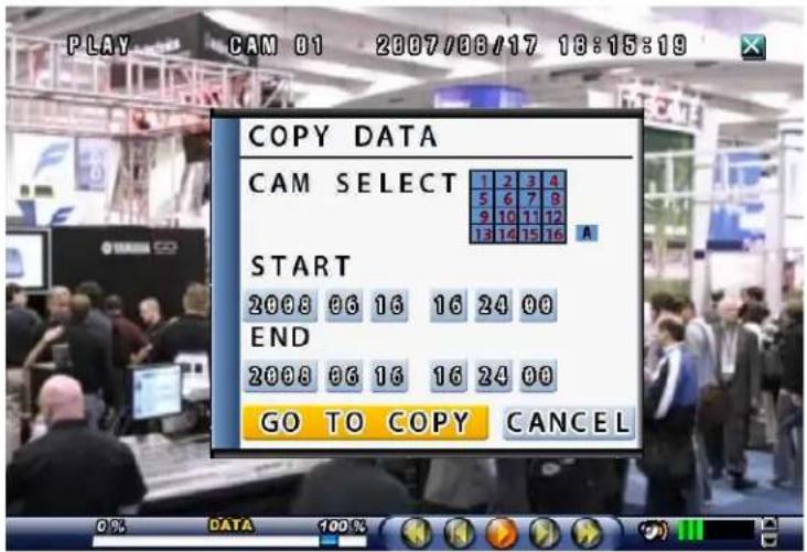
To set the ending time and date to copy, right-click on the replaying screen again, and the COPY DATA window that contains end time for copying will be displayed (See Fig.6-52). Set the ending time and date to copy as described above.
To select the COPY MODE, click on the GO TO COPY button (See Fig.6-52), and the COPY window (See Fig.6-46) will be displayed. The time and date (starting time and ending time) to copy can be changed on the COPY window as well (See section 6-11.2).
[Fig.6-52 End Copy Time Setup window]
- Choose one among NETWORK, USB, CD and DVD which are ready to copy (See section 6-11.1).
Select COPY Mode
Only when the device and media are ready to copy, the Ready on the corresponding device and media will be displayed.

USB COPY
Save the recorded data in USB Device.
Click the USB Device button to start copying.

CD-RW COPY
Save the recorded data on CD-R/W Media.
Click the CD-R/W button to start copying.

DVD-RW COPY
Save the recorded data on DVD-R/W Media.
Click the DVD-R/W button to start copying.
- As soon as one of the above buttons is clicked, copying will start along with displaying the icon shown in Fig.6-53.
The following icon indicates that copying is in process.

[Fig.6-53 Copying Icon]
6-11.5. PLAYER / AVI File Format
Copying the Recorded data with the PLAYER
- If the PLAYER in the COPY menu is selected by clicking, the recorded data will be saved along with the PLAYER (Refer to Section 8-5 PLAYER for more information) so that you can easily replay the saved data in anywhere and PC.

[Fig.6-54 Copying with Player/AVI]
Copying the AVI File Format
- If the AVI in the COPY menu is selected by clicking, it allows you to save a video clip as AVI File Format. AVI File also includes audio if recorded.
7
SETUP
CONTENTS
7-1. SETUP 78
7-2. SYSTEM....79
7-2.1. SYSTEM NAME....80
7-2.2. LANGUAGE....81
7-2.3. TIME / DATE 81
7-2.4. SYSTEM CONFIG 83
7-2.4.1. FACTORY DEFAULT 84
7-2.4.2. LOAD CONFIG / BACKUP CONFIG 85
7-2.5. PASSWORD 87
7-2.6. IR REMOTE ID 88
7-2.7. FIRMWARE UPDATE 89
7-2.8. SYSTEM INFO 89
7-3. DISK MANAGER 90
7-3.1. HDD WRITE FAIL 91
7-3.2. HDD OVERWRITE 91
7-3.3. FORMAT 91
CONTENTS
7-4. CAMERA 92
7-4.1. CAMERA ON/OFF 93
7-4.2. CAMERA NAME (CAMERA TITLE) 93
7-4.3.BUZZER....94
7-4.4. RELAY....94
7-4.5. PAN/TILT SETTINGS 95
7-4.6 DISPLAY 99
7-4.7 SEQUENCING DWELL TIME 99
7-5. AUDIO 100
7-5.1. MICROPHONE VOLUME 100
7-6. RECORD 101
7-6.1. RECORD ICON DISPLAY....101
7-6.2. ALL MANUAL / TIMER RECORDING BUTTON....102
7-6.3. ALL MOTION ON / OFF, SENSITIVITY SETTING 103
7-6.4. ALL SENSORS ON / OFF 104
7-6.5. SIZE (RECORDING RESOLUTION) 104
7-6.6. RECORDING SPEED....105
7-6.7. RECORDING QUALITY 106
7-6.8. RECORDING MODE....107
7-6.8.1. MANUAL RECORDING....107
7-6.8.2. MANUAL EVENT RECORDING....107
7-6.8.3. TIMER RECORDING (SCHEDULE RECORDING)....107
7-6.8.4. TIMER EVENT RECORDING 107
7-6.9. RECORDING BY MOTION DETECTION....108
7-6.10. RECORDING BY SENSOR (PIR SENSOR).... 117
CONTENTS
7-7. NETWORK 119
7-7.1. IP MODE 119
7-7.2. GATEWAY, SUBNET, IP ADDRESS 120
7-7.3. PORT 121
7-7.3.1 PORT FORWARDING 121
7-7.4. MAC ID 121
7-7.5. MNS (MAC NAME SERVER) 122
7-7.6. DDNS (DYNAMIC DOMAIN NAME SYSTEM)....123
7-7.7. HOW TO SETUP AND USE THE DDNS....125
7-7.7.1. ROUTER....125
7-7.7.2. REGISTRATION TO THE DDNS SERVER 125
7-7.8. EMAIL NOTIFICATION....126
7-1. SETUP

[Fig.7-1 Setup Icon on MENU window]

It is possible to set up the menus in the LIVE mode and partly in the RECORD mode.
- Click the "SETUP" button on the MENU window and the SETUP menu will be displayed.
- Click the "EXIT" button to return to the previous mode.

[Fig.7-2 SETUP menu]
7-2. SYSTEM
- Click the "SYSTEM" button in the SETUP menu, and the SYSTEM menu shown in Fig.7-3 will be displayed.
- Click the "EXIT" button to return to the SETUP menu.

[Fig.7-3 SYSTEM menu]
7-2.1. SYSTEM NAME
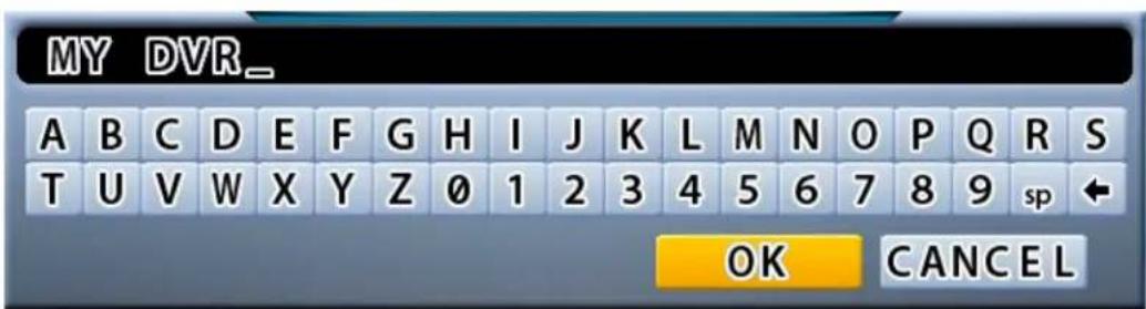
- Click the "SYSTEM NAME" button in the SYSTEM menu, then the On Screen Keyboard will display as shown in Fig 7-5.
- Delete the existing SYSTEM NAME with the ← button on the On Screen Keyboard.
- Enter the new SYSTEM NAME using the On Screen Keyboard and click on the OK button to save.
- Click the "EXIT" button to return to the SYSTEM menu.

[Fig.7-4 System name button]
[Fig.7-5 On Screen Keyboard]

Note: You should type the System Name up to 15 characters in order to utilize the MNS server (See section 7-7.5.)
7-2.2. LANGUAGE
- Click the "LANGUAGE" button in the SYSTEM menu, then the LANGUAGE submenu will display.
- Click one of Languages among English, Korean, Chinese, Japanese, Russian, Finish, Spanish, Portuguese and German.
- Click the

"EXIT" button to return to the SYSTEM menu.
LANGUAGE
: ENGLISH
[Fig.7-6 LANGUAGE button]
7-2.3. TIME / DATE
- Click the "TIME/DATE" button in the SYSTEM menu, then the TIME/DATE menu will be displayed (See Fig.7-7).
- Click the "EXIT" button to return to the SYSTEM menu.

[Fig.7-7 TIME / DATE menu]
- TIME FORMAT Click the TIME FORMAT button, then select 24 HOUR or 12 HOUR by clicking the mouse.
TIME FORMAT : 24 HOUR
[Fig.7-8 Time Format button]
- TIME Settings Click the button (AM or PM and hour/minute/second) and select one of the values in the
hour/minute/second selection table by clicking the mouse.

[Fig.7-9 Time Setting]
- DATE FORMAT
There are three formats to display the time and date as follows.
• MM / DD / YYYY: For U.S.A.
• YYYY / MM / DD: For Asian countries.
• DD / MM / YYYY: For European countries.
Click the mouse on the DATE FORMAT button to change, and then select a DATE FORMAT among YYYY/MM/DD, DD/MM/YYYY and MM/DD/YYYY.

[Fig.7-10 Date Format button]
- DATE Settings
Click the DATE button (month, date and year) and select the Date on the calendar by clicking the mouse. Select the month (year) by clicking the ◀ button or ▶ button.

[Fig.7-11 Date Settings button]
▪ DISPLAY
It enables you to display the time and date on the Live screen.
Click the DISPLAY button to set display on or off.

[Fig.7-12 Display button]

Note: Setting the new time will cause loss of recording data. After setting the time, HDD should be formatted prior to start recording.
7-2.4. SYSTEM CONFIG
- Click the "SYSTEM CONFIG" button in the SYSTEM menu, and then the SYSTEM CONFIG menu will be displayed (See Fig.7-13).
- Click the "EXIT" button to return to the SYSTEM menu.

[Fig.7-13 SYSTEM CONFIG]
7-2.4.1. FACTORY DEFAULT
- Click the "FACTORY DEFAULT" button in the SYSTEM CONFIG menu, and you will be asked as shown in Fig.7-15.
FACTORY DEFAULT : FACTORY DEFAULT
[Fig.7-14 Factory Default button]
- Click the "OK" button in Fig.7-15 to reset to the Factory Default Values, and then the system will save the factory default values (settings). Click the CANCEL button to cancel.

[Fig.7-15 Confirmation window of Factory Default]
7-2.4.2. LOAD CONFIG / BACKUP CONFIG
You can save up to four different settings in the BACKUP CONFIG and load the files in the LOAD CONFIG to change the settings to the system.
- LOAD CONFIG
This function is to load the changed settings to the system.
- Click the LOAD CONFIG button and then the LOAD CONFIG window will be displayed (See Fig.7-17).
- Select a backup file among FILE 1, FILE 2, FILE 3 and FILE 4 by clicking the mouse.
- Click the LOAD button to change the settings (See Fig.7-17).
- Click the CANCEL button to cancel.

[Fig.7-16 LOAD CONFIG button]
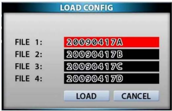
[Fig.7-17 LOAD CONFIG window]
- BACKUP CONFIG
This function is to save the current settings to load the settings to the system. Save the current settings in the BACKUP CONFIG in order to load it to the system in the near future whenever you change the settings.
- Click the BACKUP CONFIG button and then the BACKUP CONFIG window will be displayed (See Fig.7-19).
- Select a blank file among FILE 1, FILE 2, FILE 3 and FILE 4 by clicking the mouse.
- Click the BACKUP button in the BACKUP CONFIG window, then type a file name by using the On Screen Keyboard and click OK to save the current setting (See Fig.7-19).
- To delete, click the mouse on the saved file and click the DELETE button.
- Click the CANCEL button to cancel.

[Fig.7-18 BACKUP CONFIG button]

[Fig.7-19 BACKUP CONFIG window]
7-2.5. PASSWORD
ON/OFF
Select ON or OFF by clicking the mouse.
If the ON is selected, the password has to be entered to get into the SETUP mode, RECORD mode, COPY mode, REPLAY mode, and when trying to connect the network through the DVR Master.
- PASSWORD CHANGE
Click the password "*******" button and the On Screen Keyboard will be displayed as shown in Fig.7-20. The factory default password is "11111111".
Delete the existing password with the ➕ button on the On Screen Keyboard. Enter the new password by using the On Screen Keyboard and click on the OK button to save. The password should be 8 digits.
If you executed the factory default setting, the existing password will be changed to "11111111".
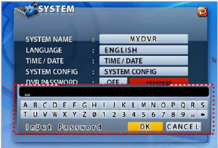
[Fig.7-20 PASSWORD KEYBOARD window]

Note: Don't forget the password.
7-2.6. IR REMOTE ID
Up to 16 DVR systems can be controlled by only one remote controller we provided, but IDs should be assigned on each of the systems. You don't have to assign any ID on the single unit and you can control the system with the provided remote controller without IR REMOTE ID, which is in the OFF mode (Skip this section).
- Click the IR REMOTE ID button and select one among OFF, 1 through 16 to assign an ID for the system by clicking the mouse.

[Fig.7-21 IR REMOTE ID button]
- When an IR Remote ID is assigned in the SYSTEM menu, press the "ID" button and the same channel button on the remote controller as an assigned ID in the SYSTEM menu to match the IDs between the system and the remote controller. And then press the "ID" button one more time for setting an ID.
When the "ID" button and the channel button are pressed on the remote controller,
- if the channel button is identical to the assigned ID, the Detect IR ID as shown in Fig.7-22 will be displayed along with the IR ID number.
- if not, the IR ID Denied as shown in Fig.7-23 will be displayed along with the denied IR ID number.

[Fig.7-22 DETECT IR ID Message]

[Fig.7-23 IR ID DENIED Message]
7-2.7. FIRMWARE UPDATE
There are two ways to update the firmware through USB memory and the DvrMaster (GUI). We recommend users to update the firmware only in the LIVE mode.
By USB memory
- Format the USB with your computer and save the firmware file on it (not including folder).
- Plug it on the USB port on the DVR.
- Click the mouse on the SELECT button in the SYSTEM menu and the FIRMWARE LIST will be displayed.
- Click on the list, and then You will be asked, OK or CANCEL.
- Click the OK button to update the firmware and the system will automatically start rebooting.
- Click the CANCEL button to cancel.
By DvrMaster (GUI)
Refer to section 8-4.1 ☐ Firmware Update on page 140.
7-2.8. SYSTEM INFO
- Click the "SYSTEM INFO" button in the SYSTEM menu and the SYSTEM INFO that contains the system version and the last updated date will be displayed.
- Click the (EXIT) button to return to the SETUP menu.

[Fig.7-24 SYSTEM INFORMATION window]
7-3. DISK MANAGER
- Click the “DISK MANAGER” button in the SETUP menu and the DISK MANAGER window will be displayed (See Fig.7-25).
- Click the (EXIT) button to return to the SETUP menu.
- A DVD R/W (USB) and 1 Hard Disk Drives can be installed, and all information in regards to the drives will automatically display on the DISK MANAGER window.

[Fig.7-25 DISK MANAGER window]
7-3.1. HDD WRITE FAIL
If HDD is in full and the OVERWRITE on the HDD is turned OFF in the recording mode, the system will activate the relay output (See section 5-4.3) for a siren or other device.
- Click the HDD WRITE FAIL button in the DISK MANAGER window and select RELAY 1 OUT or DISABLE.

[Fig.7-26 HDD Write Fail button]
7-3.2. HDD OVERWRITE
Click the OVERWRITE button to select the ON or the OFF. If the ON is selected, the system continues recording by overwriting start from the first index of the recorded file even though the space of HDD is in full. If the OFF is selected, the system will stop recording when the space of HDD is in full.

[Fig.7-27 Overwrite button]
7-3.3. Format
When you install the new Hard Disk Drives (HDD), it should be formatted before recording. Formatting is possible only when the system is in the LIVE mode.
- Click the "HDD or USB" button to format and then the HDD or USB FORMAT message box will be displayed (See Fig.7-28).
- Click the "OK" button, and you can see the formatting process of the HDD.
- Click the "CANCEL" button to return to the Disk Manager.
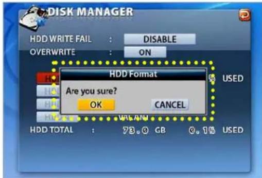
[Fig.7-28 HDD FORMAT window]
7-4. CAMERA
- Click the "CAMERA" button in the SETUP menu and the CAMERA menu will be displayed (See Fig.7-29). To change the settings in the CAMERA menu, stop recording by clicking the RECORD icon on the MENU window. It is possible only in the LIVE mode.
- Click the UP/DOWN button on the right hand side of the CAMERA menu to switch the page.
- Click the (EXIT) button to return to the SETUP menu.

[Fig.7-29 CAMERA menu]
7-4.1. Camera ON/OFF
* Click on each of the channels to select the "O" or "X" in the CAMERA menu. If the "O" is selected, the corresponding video channels (CAM 01 through CAM 16) will be displayed on the screen. If the "X" is selected, the corresponding video channels (CAM 01 through CAM 19) won't be displayed.

[Fig.7-30 Camera ON/OFF button]
7-4.2. Camera Name (Camera Title)
- Click the NAME (Camera Title) button in the CAMERA menu and the On Screen Keyboard will be displayed as shown in Fig.7-31.
Delete the existing NAME (Camera Title) with the + button on the On Screen Keyboard. - Enter the new NAME up to 8 characters by using the On Screen Keyboard and click on the OK button to save. Click on the CANCEL button to cancel.
- Click the (EXIT) button to return to the SETUP menu.

[Fig.7-31 Camera Name Setting Keyboard window]
7-4.3. Buzzer
In order to alert users, the Buzzer will sound at that time video signal lost.
- Click on each of the channels you wish to turn the buzzer "ON" or "OFF". If the "O" is selected, the buzzer will sound when video signal lost and if the "X" is selected, the buzzer won't sound.

[Fig.7-32 Buzzer button]
7-4.4. Relay
The system will automatically activate a siren or other device through the Relay Output on the rear panel when video signal lost.
- Click on each of the channels you wish to select the Relay Output "O" or "X". If the "O" is selected, the Relay Output will be turned on to activate a siren or other device when video signal lost.
[Fig.7-33 Relay OFF]
[Fig.7-34 Relay ON button]
7-4.5. Pan/Tilt Settings
- Click the PAN/TILT button on the corresponding channels in the CAMERA menu, then the PAN/TILT window will be displayed as shown in Fig.7-36.
- Click the (EXIT) button to return to the CAMERA menu.

[Fig.7-35 PAN/TILT button]
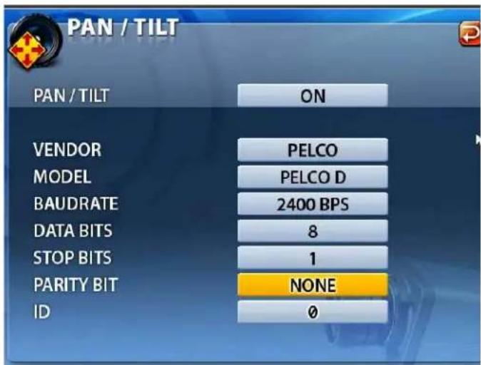
[Fig.7-36 PAN/TILT window]
- Pan/Tilt Vendor select
Click the "PAN/TILT" button in the PAN/TILT window, then the vendor lists will show up.
Select a vendor on the vendor lists by clicking the mouse.
| PAN / TILT | ON |
[Fig.7-37 PAN/TILT]

[Fig.7-38 PAN/TILT Vendor lists]
- Model
Click the "MODEL" button in the PAN/TILT window and then select the model on the pop-up lists by clicking the mouse.

[Fig.7-39 MODEL button]

[Fig.7-40 PAN/TILT Model pop-up window]
- Baud rate
Click the "BAUD RATE" button in the PAN/TILT window and choose a value among 1200bps, 2400bps, 4800bps, 9600bps, 19200bps, 38400bps, 57600bps and 115200bps on the Baud Rate pop-up window by clicking the mouse.
BAUDRATE
9600 BPS
[Fig.7-41 BAUDRATE button]

bar
| Item | Value (BPS) | |---|---| | 1200 | 1200 | | 2400 | 2400 | | 4800 | 4800 | | 9600 | 9600 | | 19200 | 19200 | | 38400 | 38400 | | 57600 | 57600 | | 115200 | 115200 |[Fig.7-42 Baud Rate pop-up window]
- Data Bits
Click the "DATA BITS" button in the PAN/TILT window and choose a value among 5, 6, 7 and 8 on the Data Bits pop-up window by clicking the mouse.
DATA BITS
8
[Fig.7-43 DATA BITS button]
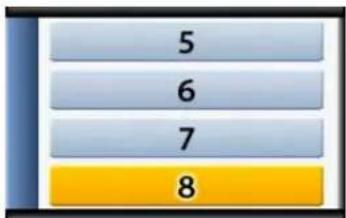
bar
| Category | Value | |---|---| | 5 | 5 | | 6 | 6 | | 7 | 7 | | 8 | 8 |[Fig.7-44 Data Bits pop-up window]
- Stop Bits
Click the "STOP BITS" button in the PAN/TILT window and select 1 or 2 on the Stop Bits pop-up window by clicking the mouse.

[Fig.7-45 STOP BITS button]
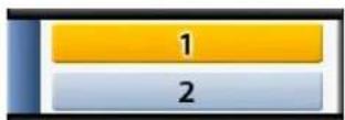
[Fig.7-46 Stop Bits pop-up window]
- Parity Bit
Click the "PARITY BIT" button in the PAN/TILT window and choose a value among NONE, ODD, EVEN, STICK and ZERO on the Parity Bit pop-up window by clicking the mouse.

[Fig.7-47 PARITY BIT button]
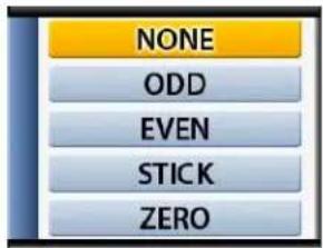
[Fig.7-48 Parity Bit pop-up window]
- PTZ ID
- Click the PTZ ID button in the PAN/TILT window, then On Screen Keyboard will show up.
- Delete the current ID with the button and choose a number among "0" to "255" by using the On Screen Keyboard, and then click OK button to save it. The ID should be identical to one PTZ camera has.
- Click the "CANCEL" button to return to the previous value.

Fig. 7-48-1 PTZ ID
7-4.6 Display
- Click the DISPLAY button in the CAMERA menu and select the ON or OFF. If the "ON" is selected, the camera name (camera title) in the LIVE mode will be displayed on the screen. If the "OFF" is selected, the camera name (camera title) in the LIVE mode won't be displayed.
DISPLAY
ON
[Fig.7-49 Display ON/OFF button]
7-4.7 Sequencing dwell time
- Click the "SEQUENCING DWELL" button in the CAMERA menu and choose a value among 1, 2, 3, 4 and 5 seconds on the dwell time pop-up window by clicking the mouse.
SEQUENCING DWEL TIME
1 SECOND
[Fig.7-50 Sequencing Dwell Time button]
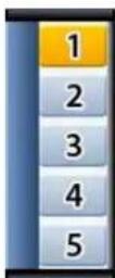
[Fig.7-51 Sequencing Dwell Time pop-up]
7-5. AUDIO
- Click on the AUDIO button in the SETUP menu and then the AUDIO menu will be displayed on the screen.
- Click the (EXIT) button to return to the SETUP menu.
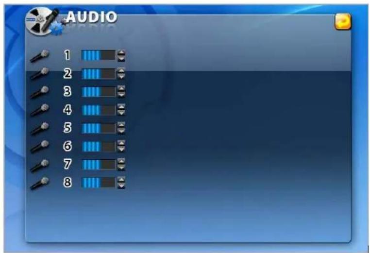
[Fig.7-52 AUDIO menu]
7-5.1. Microphone Volume
- Adjust audio volume by clicking the ▲ or ▼ button.

[Fig.7-53 Microphone Volume control button]
7-6. RECORD
- Click the "RECORD" button in the SETUP menu and then the RECORD menu will be displayed as shown in Fig.7-54.
- Click the UP/DOWN button on the right hand side of the RECORD menu to switch the page.
- Click the (EXIT) button to return to the SETUP menu.
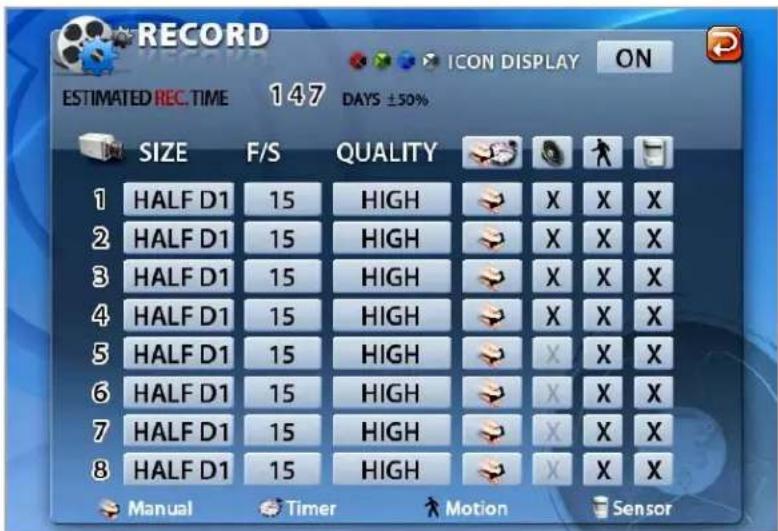
- The Recording Icons depends on recording modes are displayed in the upper left corner of the screen.
- To turn the Recording Icon OFF, click the DISPLAY ON in the RECORD menu and then it will be turned OFF. You can select the value ON or OFF by repeatedly clicking the mouse.

[Fig.7-55 Record ICON Display button]
7-6.2. All Manual / Timer recording button
- Click the All Manual / Timer recording button in the RECORD menu, then the All Manual / Timer recording button will be displayed as shown in Fig.7-57.
- Select the Manual Recording button or Timer Recording button for all the channels by clicking the mouse in Fig.7-57.
- See section 6-9.1 through 6-9.7 on page 56 through 60 for more information related to recording.

[Fig.7-56 All Manual / Timer button]
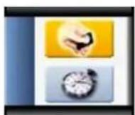
[Fig.7-57 All Manual / Timer pop-up]
7-6.3. All Motion ON / OFF, Sensitivity Setting
- Click the 🎨 button in the RECORD menu, then the ALL MOTION setup pop-up window will be displayed as shown in Fig.7-59.
- By clicking the mouse, select the ALL ENABLE on the pop-up window (See Fig.7-59) to enable the system to start recording by motion detection for all the channels.
- By clicking the mouse, select the ALL DISABLE on the pop-up window (See Fig.7-59) to disable the system to start recording by motion detection for all the channels.
By clicking the mouse, select the SENSITIVITY HIGH on the pop-up window (See Fig.7-59) and choose one of the sensitivity among LOW, 1, 2, 3 and HIGH for all the channels with the mouse's wheel, and then click it to save. - See section 6-9.1 through 6-9.7 on page 56 through 60 for more information related to recording.

[Fig.7-58 All Motion Setup button]
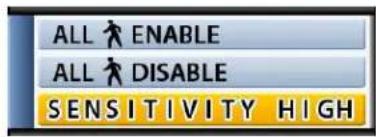
[Fig.7-59 All Motion Setup pop-up window]
SENSITIVITY HIGH
[Fig.7-60 All Motion Sensitivity setup button]
7-6.4. All Sensors ON / OFF
- Click the button in the RECORD menu, then the ALL SENSOR setup pop-up window will be displayed as shown in Fig.7-62.
- By clicking the mouse, select the ALL ENABLE on the pop-up window (See Fig.7-62) to enable the system to start recording by Sensor (Passive Infrared sensor) for all the channels.
By clicking the mouse, select the ALL DISABLE on the pop-up window (See Fig.7-62) to disable the system to start recording by Sensor (Passive Infrared sensor) for all the channels.

[Fig.7-61 All Sensor Setup button]

[Fig.7-62 All Sensor Setup pop-up window]
7-6.5. Size (Recording Resolution)
Select the size of the screen for recording. The larger the size selected, the better display quality is but the larger the data becomes.
- Click the SIZE (Recording Resolution) button on each of the channels in the RECORD menu, then the SIZE (Recording Resolution) pop-up window will be displayed as shown in Fig.7-64.
* Select one of the Resolution among D1, HALF D1 and CIF on the pop-up window by clicking the mouse.

[Fig.7-63 Record Size button]

[Fig.7-64 Record Size pop-up window]
7-6.6. Recording Speed
- Click the F/S (Frames Per Seconds: Recording Speed) button on each of the channels in the RECORD menu, then the Recording Speed pop-up window will be displayed as shown in Fig.7-66.
- Select one of the Recording Speed among AUTO, 30, 15, 10, 7, 5, 3, 2, 1 and OFF on the pop-up window by clicking the mouse.
If the AUTO is selected on all the channels, the Recording Speed on all the channels should be the same. If the OFF is selected, the corresponding channel won't be recording.

[Fig.7-65 Record Speed button]

[Fig.7-66 Record Speed pop-up]
| NTSC | 30 25 |
| 15 12 | |
| 10 8 | |
| 7 6 | |
| 5 5 | |
| 3 3 | |
| 2 2 | |
| 1 1 | |
| OFF |

[Fig.7-67 Recording Speed for each channel]
7-6.7. Recording Quality
- Click the QUALITY button on each of the channels in the RECORD menu, then the QUALITY pop-up window will be displayed as shown in Fig.7-69.
- Select one of the Recording Quality among LOW, NORMAL, HIGH and BEST on the pop-up window by clicking the mouse.

[Fig.7-68 Record Quality button]

[Fig.7-69 Record Quality pop-up]
7-6.8. Recording Mode
The factory default setting for Recording is the Manual Recording (or called Continuous Recording), which keeps recording continuously if the OVERWRITE is set ON in the DISK MANAGE menu. This Manual Recording mode is not only one of the most popular Recording modes for users, but also one of the most convenient Recording modes to use. Users can select one of the following Recording modes depends on their application.
7-6.8.1. Manual Recording
See section 6-9.1 on page 56.
7-6.8.2. Manual Event Recording
See section 6-9.2 on page 56.
7-6.8.3. Timer Recording (Schedule Recording)
See section 6-9.3 on page 57.
7-6.8.4. Timer Event Recording
See section 6-9.4 on page 58.
7-6.9. Recording by Motion Detection
When the menu of motion is properly set up (See section 7-6.3 for all the channels and this section for each of the channels) and detected motion of objects, the system begins recording automatically. The recording icon on the MENU window should be selected in this recording mode. If not, it won't be recording.
- Click the mouse on the 📀 button for each of the channels in the RECORD menu, then the MOTION menu will be displayed on the screen as shown in Fig.7-70.
- Click the (EXIT) button to return to the RECORD menu.

The system will start recording when MOTION is detected and the ON is selected in the MOTION menu by clicking the mouse. If the OFF is selected, the system won't be recording.

[Fig.7-71 MOTION ON/OFF button]
▪ Pre-Alarm Time Setup
Allows you to record a section of video just prior to Motion or Sensor activation. Click the mouse on the PRE in the MOTION menu and choose one of the values among 1 through 30 seconds in the pop-up table by clicking.
PRE
2
SECOND
[Fig.7-72 Pre-Record Time setup button]
- Motion Hold Time Setup
The system continues recording for the MOTION HOLD TIME and finishes the recording. Click the mouse on the HOLD in the MOTION menu and choose one of the values among 1 through 30 seconds in the pop-up table by clicking.
HOLD
3
SECOND
[Fig.7-73 Hold-Record Time Setup button]
- Spot Setup
If the "ON" is selected by clicking the mouse on the SPOT button in the MOTION menu, a full screen will display when a motion is detected. If the "OFF" is selected, the full screen won't be displayed even though motion of objects is detected.
SPOT
OFF
[Fig.7-74 Spot Setup button]
Region
The Motion Detection Area displays in blue on the screen, and it turns to doubly-boxes when the motion is detected. The white color on the screen represents none of detection area. There are three kinds of REGION settings as below.
Click the DETECT AREA button in the MOTION menu, and then the setting window for Motion Detection Area will be displayed in blue as shown in Fig.7-75.
Right-click on the setting window for Motion Detection Area (Fig.7-75), and then the pop-up setting window for Motion Detection Area will be displayed (Fig. 7-76).
Click the EXIT button to return to the MOTION menu.

natural_image
Interior view of a large indoor space with people gathered around tables and chairs, no visible text or symbols.[Fig.7-75 Motion Detect Area
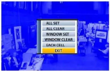
[Fig.7-76 pop-up setting window for Motion Detect Area]
EXIT
[Fig.7-77 EXIT button]
By All Set
Right-click on the setting window for Motion Detection Area (Fig.7-75), and then the pop-up setting window for Motion Detection Area will be displayed (Fig. 7-76).
By clicking the mouse, select the ALL SET button on the pop-up setting window. Motion Detect Area displays in blue on the screen as shown in Fig. 7-78.
Click the EXIT button to return to the MOTION menu.
The Factory default value is the ALL SET.

natural_image
Interior view of a busy trading floor with numerous people and display tables under blue lighting (no visible text or signage)[Fig.7-78 All Set screen]
- All Clear
Right-click on the setting window for Motion Detection Area (Fig.7-75), and then the pop-up setting window for Motion Detection Area will be displayed (Fig. 7-76).
By clicking the mouse, select the ALL CLEAR button on the pop-up setting window in order to clear the Motion Detect Area. The window turns to white color as shown in Fig. 7-79.
Click the EXIT button to return to the MOTION menu.

natural_image
Interior view of a busy indoor exhibition hall with attendees seated at booths and banners (no visible text or signage)[Fig.7-79 All Cleared screen]
By Window Set
Right-click on the setting window for Motion Detection Area (Fig.7-75), and then the pop-up setting window for Motion Detection Area will be displayed (Fig. 7-76).
By clicking the mouse, select the WINDOW SET button on the pop-up setting window. Click one of cells for the starting point of the area which you would like to designate, and then click the other one of cells for the ending point of area until the motion detection area is the size you want it to be. The multiple motion areas can be set on each of cameras.
The motion detection by Window Set will be made on the designated area only.
Click the EXIT button to return to the MOTION menu.

natural_image
Interior view of a busy indoor exhibition hall with people gathered around tables and display boards (no visible text or signage)[Fig.7-80 Window Set screen]
- Window Clear
Right-click on the setting window for Motion Detection Area (Fig.7-75), and then the pop-up setting window for Motion Detection Area will be displayed (Fig. 7-76).
By clicking the mouse, select the WINDOW CLEAR button on the pop-up setting window in order to clear the Motion Detection Area, and then the motion detection area you have created will be displayed. Click the starting point and the ending point as much as you wish to clear or it can be cleared by ALL CLEAR as described above (See ALL CLEAR).

natural_image
Interior view of a busy trading floor with people at booths and a computer mouse icon overlay (no readable text or symbols)[Fig.7-81 Window Clear setup screen]
By Each Cell
Right-click on the setting window for Motion Detection Area (Fig.7-75), and then the pop-up setting window for Motion Detection Area will be displayed (Fig. 7-76).
By clicking the mouse, select the EACH CELL button on the pop-up setting window. Click the mouse on each of the cells as much as you would like to designate the Motion Detection Area.
To clear, click the designated cells.

natural_image
Interior view of a busy trading floor with people at booths and blue square overlays (no visible text or symbols)[Fig.7-82 Each Cell Setup screen]
- Buzzer
Click the buzzer button in the MOTION menu to turn the buzzer "ON" or "OFF". If the "ON" is selected, the buzzer will sound when a motion is detected. If the "OFF" is selected, the buzzer won't sound.
BUZZER
OFF
[Fig.7-83 Buzzer ON/OFF]

Note : Please pay attention to the following directions in order to use the Motion Detection function properly:
- Adjust the sensitivity level and motion area to fit your requirements.
- Do not use this function in an area where many objects are continuously moving. In case of this, change the recording mode to the Continuous (Manual) Recording mode.
- Use a high quality camera that does not generate video static or "noise". The motion detection algorithm recognizes this "noise" as a motion and records the noise even if there was no actual motion.
- Do not point the camera toward a strong and changing lighting source; it can activate false motion detection.
7-6.10. Recording by Sensor (PIR Sensor)
- Click the mouse on the button for each of the channels in the RECORD menu, and then the SENSOR menu will be displayed on the screen as shown in Fig. 7-84.
- Click the (EXIT) button to return to the RECORD menu.

[Fig.7-84 SENSOR window]
- ON/OFF
The system will start recording when an Alarm is detected and the ON is selected in the SENSOR menu by clicking the mouse. If the OFF is selected, the system won't be recording.
If you select "OK", it will be recorded when only sensor is activated.

[Fig.7-85 SENSOR ON/OFF button]
- Pre-Alarm Time Setup
Allows you to record a section of video just prior to Sensor activation. Click the mouse on the PRE in the SENSOR menu and choose one of the values among 1 through 30 seconds in the pop-up table by clicking.
PRE
1 SECOND
[Fig.7-86 Pre-Alarm Time Setup button]
- Alarm Hold Time Setup
The system continues recording for the Alarm HOLD TIME and finishes the recording. Click the mouse on the HOLD in the SENSOR menu and choose one of the values among 1 through 30 seconds in the pop-up table by clicking.
HOLD
10 SECOND
[Fig.7-87 Alarm Hold Time Setup button]
- Spot Setup
If the "ON" is selected by clicking the mouse on the SPOT button in the SENSOR menu, a full screen will display when the sensor is activated. If the "OFF" is selected, the full screen won't be displayed even though the sensor is activated.
SPOT
OFF
[Fig.7-88 Spot Setup button]
Buzzer
Click the buzzer button in the SENSOR menu to turn the buzzer "ON" or "OFF". If the "ON" is selected, the buzzer will sound when a sensor is activated. If the "OFF" is selected, the buzzer won't sound.
BUZZER
OFF
[Fig.7-89 Buzzer ON/OFF]
7-7. NETWORK
- Click the "NETWORK" button in the SETUP menu, and then the NETWORK menu will be displayed on the screen as shown in Fig.7-90.
- Click the (EXIT) button to return to the SETUP menu.
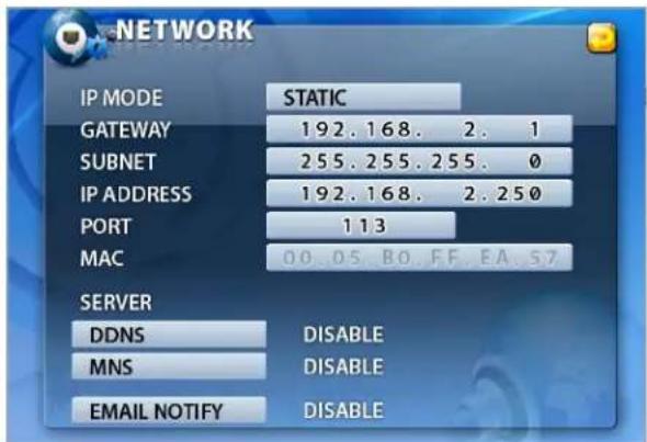
[Fig.7-90 NETWORK menu]
7-7.1. IP Mode
When the system uses the same IP address every time it connects to the network, it is known as a static IP address. If the system's IP address changes frequently, it is called a dynamic IP address. Check with your Internet Service Provider to determine which IP address was given. This manual will guide users through the setup process for both types.
DYNAMIC IP: automatically receives IP address from the router or gateway. With Dynamic IP, It doesn't need to enter the GATEWAY ADDRESS, SUBNET MASK, and IP ADDRESS.
STATIC IP: requires you to enter the GATEWAY ADDRESS, SUBNET MASK, and IP ADDRESS.
- Click theIP MODE" button in the NETWORK menu, and then the IP mode pop-up window will be displayed on the screen (See Fig. 7-92).
- Select the STATIC or DYNAMIC by clicking the mouse depends on your networking.

[Fig.7-91 IP Mode button]
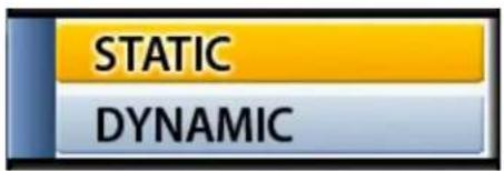
[Fig.7-92 IP Mode pop-up]
7-7.2. GATEWAY, SUBNET, IP ADDRESS
- Click the GATEWAY / SUBNET / IP ADDRESS button in the STATIC IP MODE, then the On Screen Keyboard will appear.
- Delete the current values with the + button and enter the address numbers by using On Screen Keyboard, and then click OK button to set with new address.
- Click the CANCEL button to return to the original values.
| GATEWAY | 192.168. 2. 1 |
| SUBNET | 255.255.255.0 |
| IP ADDRESS | 192.168. 2.250 |
[Fig.7-93 Address Setup window]

[Fig.7-94 On Screen Keyboard]
7-7.3. Port
- PORT is the TCP address of the program, which is used to connect to the network viewer. It can be set from 1 to 65535 values.
- Click the PORT button in the Network menu, then the On Screen Keyboard will show up.
Delete the current port number with the ← button and enter the new port number by using On Screen Keyboard, and then click "OK" button to set with new port number. - Click the "CANCEL" button to return to the default value.
| PORT | 113 |
[Fig.7-95 Port Setup window]

[Fig.7-96 Port Setup Keyboard window]
7-7.3.1 Port Forwarding
- Router has to be set as a virtual server (or port forwarding) in order to utilize the MNS (Mac Name Server) or the DDNS service to use Internet Explorer (See section 8-3) on this product.
Do not use the public port numbers.
7-7.4. MAC ID
- MAC ID is connecting address for Ethernet, every unit has 12 digit addresses (HEX 6 byte). MAC ID was already assigned with the factory default value. User can not change it.
7-7.5. MNS (MAC NAME SERVER)
As a sort of DDNS, two servers in our company are being operated so that our client can access DVR with a Dynamic IP address. If one of servers stops operating, the other one will automatically start working.
- Click the MNS button in the NETWORK menu with a mouse or buttons on the remote controller and then the MNS window will show up as below (See Fig.7-97).
- To return to the NETWORK window, click the (EXIT) button in the MNS menu.
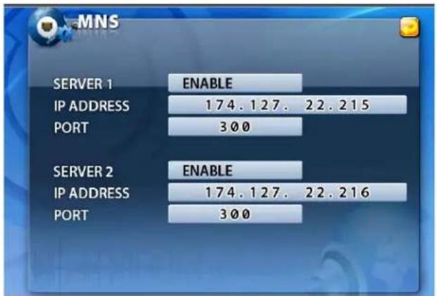
[Fig.7-97 MNS window]
- DISABLE / ENABLE
You can select the DISABLE or ENABLE button on both SERVER 1 and SERVER 2 by clicking the mouse or pressing the ENTER button on the remote controller.
"DISABLE": MSN (MAC NAME SERVER) is not working.
"ENABLE": MSN (MAC NAME SERVER) is working.

[Fig.7-98 DISABLE/ENABLE button]
- IP ADDRESS / PORT
DO NOT CHANGE THE IP ADDRESS AND PORT NUMBER IN THE MNS MENU IF YOU DON'T HAVE ANY SPECIAL SERVER TO ACCESS YOUR DVR WITH A DYNAMIC IP ADDRESS. IF YOU CHANGE THEM, YOU CAN'T NOT ONLY USE OUR MNS (MAC NAME SERVER), BUT ALSO YOUR NETWORKING WILL BE DISCONNECTED.

Note : You should type the System Name up to 15 characters in order to utilize the MNS server (See section 7-2.1.)
7-7.6. DDNS (DYNAMIC DOMAIN NAME SYSTEM)
- Select the DDNS button in the NETWORK menu by clicking the mouse or pressing the buttons on the remote controller. The DDNS menu will show up as shown in Fig. 7-99.
▪ To return to the NETWORK menu, click the (EXIT) button. - If you were in the middle of entering values on the DDNS menu, you can't exit by clicking the mouse. Choose the SERVER button in the DDNS menu by clicking the mouse and
select the DISABLE, and then click the 😊 (EXIT) button.

[Fig.7-99 DDNS menu]
"SERVER
- Choose the SERVER button in the DDNS menu by clicking the mouse or pressing the buttons on the remote controller and select the DYNDNS.ORG (or NO-IP.ORG) provided by www.dyndns.org (or www.no-ip.org) at no cost.
SERVER
DYNDNS.ORG
[Fig.7-100 SERVER button]
- HOST NAME
- Click the HOST NAME in the DDNS menu and type the HOST NAME registered to the DDNS server such as DYNDNS.ORG and NO-IP.ORG by using the On Screen Keyboard.
- After changing the values, click on the OK button.
HOST NAME
DVR.DYNDNS.ORG
[Fig.7-101 HOST NAME button]
- USER ID
- Click the USER ID in the DDNS menu and type the USER ID registered to the DDNS server by using the On Screen Keyboard.
- After changing the values, click on the OK button.
USER ID
USER
[Fig.7-102 USER ID button]
- PASSWORD
- Click the PASSWORD in the DDNS menu and type the PASSWORD registered to the DDNS server by using the On Screen Keyboard.
- After changing the values, click on the OK button.
PASSWORD


[Fig.7-103 PASSWORD button]
7-7.7. HOW TO SETUP AND USE THE DDNS
7-7.7.1. Router.
It has to be set as a virtual server (or port forwarding) in order to utilize the DDNS. There are a lot of manufacturers on the market. Please read the provided manual thoroughly before setting or visit our website at www.cloverusa.co.kr in regards to do it.
We, the manufacturer of DVR systems will not support the solution to your individual network issues.
** DDNS (Dynamic Domain Name System) is a method of keeping a domain name linked to a changing IP address. This is a useful feature since many computers do not use a static IP address.
7-7.7.2. Registration to the DDNS server
Visit at www.dyndns.org to register.
Registration to DYNDNS.ORG
- Visit at www.dyndns.com.
- Sign up for a new user name and a password: Click the Create Account on the upper right hand corner.
- After signup new user, check your e-mail and confirm an e-mail from dyndns.com.
- Go back to www.dyndns.com log in with the ID and the Password.
- After log in on dyndns.com front page, click on my services.
- Click on the Add Host Service (Next to Host Level Service).
- Click the Add Dynamic DNS Host on the Dynamic DNS.
- The window to input Host Name will pop up, and select the dyndns.org or the dvrdns.org on the pop-up window.
- To complete, click the Add Host button on the bottom.
- After registration, go to the NETWORK menu on the DVR and enter the HOST NAME, USER ID and the PASSWORD you just registered in the DDNS menu (See section 7-7.6).
7-7.8. EMAIL NOTIFICATION
- Email notification enables to notify events (sensor, motion, video loss, power on/off, power loss, record on/off, record fail, replay or copy start/stop) by sending emails to one or two email accounts.
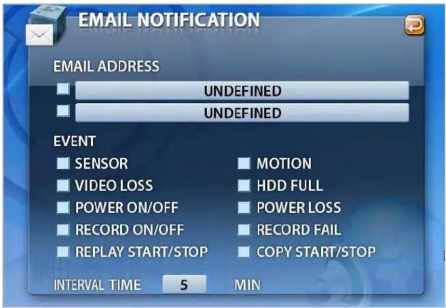
[Fig.7-104 Email Notification window]
- EMAIL ADDRESS SETUP

[Fig.7-105 Keyboard window]
- Click one of email address boxes and then the On Screen Keyboard will show up as shown Fig.7-105.
- Delete the current email address with the + button and enter an email address by using the On Screen Keyboard.
- If necessary, click the SHIFT button to enter upper cases.
- Click the OK button to save.
- Click the check box below to enable the email notification.
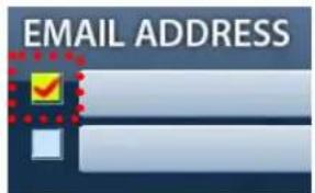
[Fig.7-106 Check Box for email]

Note : If a check box in Fig.7-106 is checked, "ENABLE" message will be displayed in the NETWORK menu, if not, "DISABLE" will be displayed.
- EVENT Setup
- Click the check boxes below to choose the events you need.
- To delete, click the check box again.

[Fig.7-107 Event setup]
- INTERVAL TIME Setup
- Click the INTERVAL TIME (see Fig.7-108) to set the interval time of sending emails and then choose the time (in minutes) on the pop-up window by clicking the mouse.
If the 5 minutes is selected, the system will automatically send only one email every 5 minutes even though a lot of events occur.
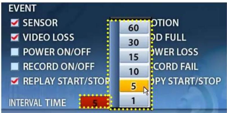
[Fig.7-108 interval time setup]
Note : If the motion is selected in Fig.7-108, you may receive numerous emails from the DVR systems due to a couple of factors such as continuous moving objects, a strong and changing lighting source, low resolution and noises of cameras. In case of this, select a longer INTERVAL TIME and refer to “Note for Motion Detection Function” on page 116.
8
Remote Host Program
CONTENTS
8-1. REMOTE PROGRAM OVERVIEW 133
8-2. INSTALLING THE PROGRAM TO PC....134
8-3. INTERNET EXPLORER....135
8-4. REMOTE HOST 137
8-4.1. SETUP....139
8-4.2. CONNECTION....142
8-4.3. CAPTURE....143
8-4.4. STATUS 144
8-4.5. REPLAY 145
8-4.6. COPY....147
8-4.7. SWITCH THE NORMAL SCREEN TO FULL SCREEN 149
8-4.8. SPEAKER / MICROPHONE 150
8-4.9. CONNECTION MODE....151
8-4.9.1. TERMINAL MODE....151
8-4.9.2. MULTI MODE 152
8-4.10. COPY IN THE TERMINAL MODE 153
8-4.11 E-MAP....155
8-4.11.1 ADDITION OF MAP 155
8-4.11.2. PLACEMENT OF CAMERAS ON THE MAP 156
8-4.11.3. USAGE OF CAMERA POSITION....157
8-4.11.4. DELETION OF CAMERA POSITION ICON 157
8-4.12 PAN / TILT & PRESET 158
8-5. PLAYER....159
8-1. Remote Program Overview
The Remote Host Program allows you to view live video, search archived video, control PTZ cameras and to set up the exact same menus as the DVR does.
The DVR system can have up to 10 simultaneous Remote Connections. Each user can perform on the DVR system and will not affect the other users. The only exception to this is accessing Setup. Only one user is allowed to access Setup at any time.
In order to log in to the DVR system, users should be requested to enter the password if the password is already turned ON in the SYSTEM menu (Click SETUP – SYSTEM). This ensures that only authorized personnel are allowed to log in.
Remote system minimum requirements
- Microsoft Windows 2000, XP or VISTA Operating System
- Pentium-4 2.0GHz or higher
• 256MB System memory
• 1024 x 768 Display Resolution, 32Bit color - Internet or LAN Connection
- TCP/IP installed
- Microsoft DirectX 9.0c
It is recommended to have DirectX 9.0c version in client PC. DirectX 9.0 is available for download from Microsoft homepage (www.microsoft.com/windows/directx).
8-2. Installing the Program to PC
Install the program into PC by using program CD (supplied) as follows.
How to install the program
- Start the operating system (Windows 2000/XP/VISTA).
- Insert the program CD into CD-ROM drive.
- Open My Computer, and then select CD-ROM drive.
- Double click Setup.EXE. The software installation will begin.
- After the installation has been completed, the DVR Master icon will be created on your desktop screen as shown below.
- Double click the DVR Master icon and the DVR Master screen appears.

DvrMaster
[Fig.8-1 DVR Master icon]
How to set Screen Resolution and Color Quality
- Click Start, point to Control Panel and then click on it.
- Double-click Display icon.
- In Display Properties Window, select Settings.
- Set Colors as True color (32 bit) and Screen area as 1024 x 768 (or 1152 x 864) pixels.
8-3. Internet Explorer
When you are trying to use this function, it is highly recommended that the password should be turned ON in the SYSTEM menu not to enable unauthorized personnel to access your DVR system (See section 7-2.5).
Up to 10 users can remotely access your DVR with the HOST NAME.
How to setup the Internet Explorer
- Registration to the www.dyndns.org (See section 7-7.7.2 on page 125).
- In the IP address box of Microsoft Internet Explorer, type the HOSET NAME (See Fig.8-2) you entered in the DDNS menu and the PORT NUMBER of the DVR, and then you will be asked to install the AciveX control software (See Fig.8-3). You should type the protocol (http://), the host name (example: cloverdvr1.dyndns.org) or the static IP address (See Fig.8-2-1) and the port number (:5800) in the IP Address box.

http://cloverdvr1.dyndns.org:5800/
[Fig.8-2 Host Name]

http://65.60.84.40:5800/
[Fig.8-2-1 IP & Port]

[Fig.8-3 DVR Master- Windows Internet Explorer]
- Click on the following message.
This site wants to install the following add-on: 'DVR Master' from 'Clover Electronics USA'. If you trust the website and the add-on and want to install it, click here.... - Click the click install ActiveX Control.... on the pop-up screen and the following window will be displayed.

[Fig.8-4 Install the DVR Master]
- Click the Install button on the above window (See Fig.8-4) and the DVR Master will be shown. Refer to the following pages in regards to the DVR Master.
8-4. Remote Host
![DVR MASTER 06/10/2008 Tue 11:34:19 Connect Comilla Player Capture P/T/Z OFF Focus Zoom SET 0 GO 12 13 STATUS CLOVER 10CHI 192.168.2.144 FPS[31] KBPS[19] RELAY OUT 14 [Fig 8-5. DVR Master]](/content/2026/05/1084259/images/124dd6c08cce61fafabe6f16a4325ff8fc3f409c8c8c2b6d163f619a520e163a.jpg)
Table. Description of Remote Host Program Button
| 1 | Minimization Button |
| 2 | Close Button |
| 3 | Current Time |
| 4 | Connection Button |
| 5 | Setup Button |
| 6 | Player Execution Button |
| 7 | Capture Button |
| 8 | Multi-Mode |
| 9 | Terminal Mode |
| 10 | E-map Button |
| 11 | Splits the screen in 4, 9 & 16ch. |
| 12 | PAN /TILT Control Button ( Control the PTZ camera from the remote site DVR) |
| 13 | Depending on the mode, it displays Status/REPLAY / COPY information. |
| 14 | Change button for STATUS / REPLAY/ COPY mode. |
| 15 | When connected, it displays the audio channel, PC Speaker & Mic control button of remote site DVR. |
| 16 | It displays the IP address, Frame rate and transfer rate. |
8-4.1. Setup
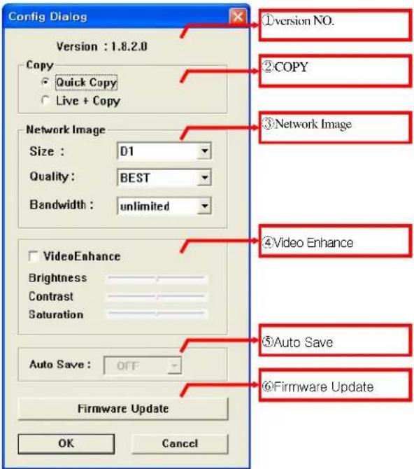
[Fig.8-6 HOST CONFIG window]
① Version number
It represents the current version number of the Firmware.
② Copy
Refer to Section 8-4.10 in regards to copying methods after selecting one between the Quick Copy and the Live + Copy.
- Quick Copy
Click on the Quick Copy for faster copying the recorded data from the DVR to the Host
Program (DVR Master) without live images. The copying speed of the Quick Copy is faster than the Live + Copy.
= Live + Copy
Click on the Live + Copy for copying the recorded data from the DVR to the Host Program (DVR Master) with live images. The copying speed of the Live + Copy is slower than the Live + Copy.
③ Network Image
Size
Choose a Size (Resolution) among D1, Half D1 and CIF you wish to display on the DVR Master by clicking the mouse. This setting does not affect the DVR.
Quality
Choose one among LOW, NORMAL, HIGH and BEST you wish to display on the DVR Master by clicking the mouse. This setting does not affect the DVR.
- Bandwidth
The default is set to unlimited. Select between 64KBPS to 10MBPS to optimize your network performance.
④ Video Enhance
- Adjust the Brightness of screen by clicking on the bar or dragging the slider on the bar.
- Adjust the Contrast of screen by clicking on the bar or dragging the slider on the bar.
- Adjust the Saturation of screen by clicking on the bar or dragging the slider on the bar.
○5 Auto Save
It enables users to save live images from the DVR system to a PC through internet.
- Select one among OFF, 1GB, 2GB, 5GB, 10GB and 50GB on the Config Dialog menu as shown in Fig.8-6 before clicking the "CONNECT" button on the DvrMaster. The "GB", Giga Bytes represent the data volume of live images you can save to a PC.
- The live images will be saved in the AutoSave Folder (Open Windows Explorer – click My Computer – click Program Files – click DvrMaster – click AutoSave).
- To replay, refer to Section 8-5 PLAYER.
○6 Firmware Update
- Save the latest Firmware to the System Files (Open Windows Explorer – click My Computer - click the Program Files – click DVR Master – click System Files).
- Click the Firmware Update button in the Fig.8-6 and then you will be asked "Do you want to update a firmware?"
- Click the Yes to update.
- Double click the latest firmware as shown in Fig.8-7 and then you will be asked "Shall I update firmware?"
- Click the OK to update. The DVR will display the "Firmware Updating....." along with the progressive bar on the screen and it will automatically reboot.

[Fig.8-7 Firmware Files]
8-4.2. Connection
There are two ways to access the DVR through the DVR Master as follows.
= With Set Direct setting
- Click the "CONNECT" button on the DVR Master and the "Connect Dialog menu" as shown in Fig. 8-8 will be displayed.
- Click the "Set Direct" in the Connect Dialog menu and click the "EDIT" button.
- Enter the IP address (or WAN IP address of the Router) and Port number, which must be the same as DVR has.
- Click the "EDIT" button again and the connection list will be created in the Name List (up to 20 lists).
- Choose a Site Name in the Name Lists and then click the "CONNECT" button In order to access the DVR.
- With Get Server setting
- Click the "CONNECT" button on the DVR Master and the "Connect Dialog menu" as shown in Fig. 8-8 will be displayed.
- Click the "Get Server" in the Connect Dialog menu and click the "EDIT" button.
- Enter the IP address, Port number and Site Name, which must be the same as the MNS has (SETUP-click NETWORK-click MNS in the NETWORK menu: Refer to section 7-7.5 MNS on page 122).
- Click the "EDIT" button again and the connection list will be created in the Name Lists (up to 20 lists).
- Choose a Site Name in the Name Lists and then click the "CONNECT" button in order to access the DVR.
- With Domain setting
- Click the "CONNECT" button on the DVR Master and the "Connect Dialog menu" as shown in Fig. 8-8 will be displayed.
- Click the "Domain" in the Connect Dialog menu and click the "EDIT" button.
- Type the DOMAIN name, Port number and User's defined name.
-
Click the "EDIT" button again and the Domain list will be created in the Name Lists (up to 20 lists).
-
Choose a Domain Name in the Name Lists and then click the "CONNECT" button in order to access the DVR.
- To register the Domain name (Host Name), refer to section 7-7.7.2 on page 125.


[Fig.8-8 Connect Dialog]
8-4.3. Capture
The current images on the screen will be captured and saved in the Printed Files (Open Windows Explorer – click My Computer – click Program Files – click DvrMaster – click Printed Files).
To play captured images, double-click one of JPEG Images in the Printed Files.
8-4.4. Status
STATUS
If the Status button on the DvrMaster is selected by clicking the mouse, the DvrMaster displays the DVR's status related to connections of cameras, sensors, relay outputs and remaining HDD (Hard Disk Drive) capacity available for recording.
![DUR MASTER 06/10/2000 Tun 15:29:57 Connect 1 Comfg Recovery Caption Terminal WT/2 OFF Status button CAMERA SENSOR HOLDOUT HDD-STATUS STATUS FORMAT CLOVER 16CH 192.16BL2.144 FPS[ 61] KBPS[ 5G]](/content/2026/05/1084259/images/6ce3f30fb1b0d612aaa0e7055058590137b0690913f72b5f58e5577a119737d0.jpg)
[Fig8-9 STATUS MODE]
8-4.5. Replay

It is possible to replay the recorded data from the DVR system by using the Replay button in Fig.8-10 in the Multi mode only (refer to section 8-4.9.2).
- Click the Replay button as shown in Fig.8-10 to playback the recorded data from the DVR system, and then the Replay Time Setup Window will be displayed.
![DVR MASTER 06/10/2008 Tue 14:30:24 Replay Time Setup Window Start Time : 09/22/2008 Sat 18:00 End Time : 09/22/2008 Sat 18:00 Start Time : 09/22/2008 Sat 18:00 Start Time : 09/22/2008 Sat 18:00 REPLAY button CLOVER TECH 190.168.7.144 FPS[ 64] KBPS[163]](/content/2026/05/1084259/images/a44aa9779b7f8585873d6e84636cfc4920f5e69b1bc32604fd59a66652a7d05e.jpg)
[Fig 8-10 Replay mode]
- After checking the Start Time and End Time on the upper part of the Replay Time Setup Window, click the Edit (Edit) button to set the Replay Start Time.
- Set the Replay Start Time in the Start Time Setting menu as shown in Fig.8-11 and click the OK button. Replaying start time setup can be possible within a recoding time extent.
- Click the Play (Play) button.
- It will start playing the recorded data and the playback control buttons will show up.

[Fig.8-11 Start Time setting]
- Playback Control
![DVR MASTER 05/10/2008 Tel 14:36:02 Connect Config Playbox Creations WT/Z OFF Replay 01 2 3 4 0 1 2 3 4 0 1 2 3 4 0 1 2 3 4 PLAY 03/22/2008 Sat 19:10:05 Playback CLOVER 16CH 197.1683.144 FPS[27, KBPS[301] RePLAY COPY Playback Control Buttons](/content/2026/05/1084259/images/e2cbb828063448be3a92da530a1afa44f852904ba7a25cdfa33d0b2df627e07b.jpg)
[Fig 8-12. Playback control]
Playback control buttons

natural_image
Vertical sequence of six abstract geometric shapes in gradient tones, no text or symbols present: Button for fast rewinding up to 128 times by repeatedly pressing.
: Button for viewing previous frame in still image.
: Play button.
: Button for viewing the next frame in still image.
: Button for fast forwarding up to 128 times by repeatedly pressing.
: It stops replaying.
8-4.6. COPY
COPY
It is possible to copy the recorded data from the DVR system to a client PC by using the Copy button in Fig.8-13 in the Multi mode only (refer to section 8-4.9.2).
- Click the Copy button as shown in Fig.8-13 to copy the recorded data from the DVR system to a PC, and then the Copy Time Setup Window will be displayed.
- The copy data will be saved in the Backup Files (Open Windows Explorer – click My Computer – click Program Files – click DvrMaster folder – click Backup Files).
![OVR MASTER 06/10/2000 Tom 14:43:01 Connect 1 Control Player Capture VIT/Z OFF SET 0 OUT 0 1 2 3 4 5 6 7 8 9 Start Time: 03/22/2006 Sat 18:10:06 End Time: 05/27/2006 Tue 18:00:22 CLOVER 1CH 192.165.2.144 FPS[30] KBPS[52] Copy Time Setup Window Copy button](/content/2026/05/1084259/images/6bc68552c09f6eb9928461f2a83caa3f1b4037808ab5a62d5945291f5388c18d.jpg)
[Fig 8-13 Copy mode]
- Check the Start Time and End Time on the upper part of the Copy Time Setup Window and click the Edit (Edit) button to set the Copy Start/End Time.
- Set the Copy Start/End Time in the Start/End Time Setting menu as shown in Fig.8-14 and click the OK button. Copying Start/End time setup can be possible within a recoding time extent.
- Select camera(s) you wish to copy by clicking "ALL" or camera channel number(s) in the Copy Time Setup Window.
"ALL" in yellow represents that all the cameras are selected.
The camera channel number(s) in yellow represents that the corresponding channel(s) are selected.
- Click the Copy (Copy) button and then the copying progressive bar as shown Fig.8-15 will show up.
- While copying, click the Stop button in the Copy Time Setup Window if you want to stop copying.
- To playback, refer to section 8-5.PLAYER.
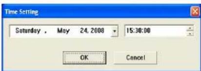
[Fig.8-14 Copy Start/End Time setting menu]
![DVR MASTER 06/10/2008 Tur 14 + 43 : 01 Crossover Config Maple Capture Tehnout Lamp P/T/Z OFF Reset SET 0 1 2 3 4 5 6 7 8 9 Start Time: 09/22/2008 Sat 16:00 Start Time: 09/22/2008 Tur 16:00 Start Time: 09/22/2008 Sat 16:10:00 Start Time: 09/22/2008 Tur 16:10:20 Start Time: 09/22/2008 Sat 16:10:30 Start Time: 09/22/2008 Tur 16:10:31 Start Time: 09/22/2008 Sat 16:10:32 Start Time: 09/22/2008 Tur 16:10:33 Start Time: 09/22/2008 Sat 16:10:34 Start Time: 09/22/2008 Tur 16:10:35 Start Time: 09/22/2008 Sat 16:10:36 Start Time: 09/22/2008 Tur 16:10:37 Start Time: 09/22/2008 Sat 16:10:38 Start Time: 09/22/2008 Tur 16:10:39 Start Time: 09/22/2008 Sat 16:40 Start Time: 09/22/2008 Tur 16:40 Start Time: 09/22/2008 Sat 16:41 Start Time: 09/22/2008 Tur 16:41 Start Time: 09/22/2008 Sat 16:42 Start Time: 09/22/2008 Tur 16:42 Start Time: 09/22/2008 Sat 16:43 Start Time: 09/22/2008 Tur 16:43 Start Time: 09/22/2008 Sat 16:44 Start Time: 09/22/2008 Tur 16:44 Start Time: 09/22/2008 Sat 16:45 Start Time: 09/22/2008 Tur 16:45 Start Time: 09/22/2008 Sat 16:46 Start Time: 09/22/2008 Tur 16:46 Start Time: 09/22/2008 Sat 16:47 Start Time: 09/22/2008 Tur 16:47 Start Time: 09/22/2008 Sat 16:48 Start Time: 09/22/2008 Tur 16:48 Start Time: 09/22/2008 Sat 16:49 Start Time: 09/22/2008 Tur 16:49 Start Time: 09/22/2008 Sat 16:50 Start Time: 09/22/2008 Tur 16:50 Start Time: 09/22/2008 Sat 16:51 Start Time: 09/22/2008 Tur 16:51 Start Time: 09/22/2008 Sat 16:52 Start Time: 09/22/2008 Tur 16:52 Start Time: 09/22/2008 Sat 16:53 Start Time: 09/22/2008 Tur 16:53 Start Time: 09/22/2008 Sat 16:54 Start Time: 09/22/2008 Tur 16:54 Start Time: 09/22/2008 Sat 16:55 Start Time: 09/22/2008 Tur 16:55 Start Time: 09/22/2008 Sat 16:56 Start Time: 09/22/2008 Tur 16:56 Start Time: 09/22/2008 Sat 16:57 Start Time: 09/22/2008 Tur 16:57 Start Time: 09/22/2008 Sat 16:58 Start Time: 09/22/2008 Tur 16:58 Start Time: 09/22/2008 Sat 16:59 Start Time: 09/22/2008 Tur 16:59 Start Time: 09/22/2008 Sat 16:60 Start Time: 09/22/2008 Tur 16:60 Start Time: 09/22/2008 Sat 16:61 Start Time: 09/22/2008 Tur 16:61 Start Time: 09/22/2008 Sat 16:63 Start Time: 09/22/2008 Tur 16:63 Start Time: 09/22/2008 Sat 16:64 Start Time: 09/22/2008 Tur 16:64 Start Time: 09/22/2008 Sat 16:65 Start Time: 09/22/2008 Tur 16:65 Start Time: 09/22/2008 Sat 16:67 Start Time: 09/22/2008 Tur 16:67 Start Time: 09/22/2008 Sat 16:73 Start Time: 09/22/2008 Tur 16:73 Start Time: 09/22/2008 Sat 16:74 Start Time: 09/22/2008 Tur 16:74 Start Time: 09/22/2008 Sat 16:75 Start Time: 09/22/2008 Tur 16:75 Start Time: 09/23/15-34-35-36-37-38-39-43-44-45-47-48-49-53-54-55-57-58-59-63-64-65-67-68-69-73-74-75-77-78-79-83-84-85-87-88-89-93-94-95-97-98-99-1M-CLOVER TECH 1HZ. IENJ. Z. IAA. FPS[3B] KBPS[5Z]](/content/2026/05/1084259/images/ec1635d0e2b60843500442ee1b7cf577af1d6ca6ed3eeee64531ffc4d1f4f307.jpg)
[Fig 8-15 Status of Copying]
8-4.7. Switch the Normal Screen to Full Screen
- Click the "FULL SCREEN" button on the DvrMaster as shown Fig.8-16 and the current screen size will be enlarged to fit the monitor's screen size, but the resolution will be lowered.
- Click the "FULL SCREEN" button again to go back to the NORMAL SCREEN.
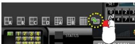
[Fig.8-16 Full Screen Button]

[Fig.8-17 Switch the Normal Screen to Full Screen]
8-4.8. Speaker / Microphone
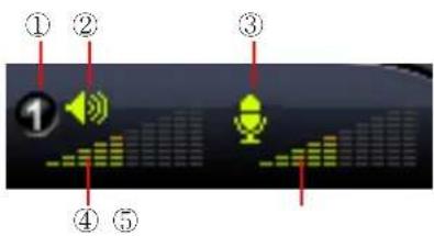
[Fig.8-18 Speaker / Microphone]
Buttons of Remote Host Program
① Audio Input channel selection: Select the same audio channel as the DVR has.
② PC Speaker ON/OFF: Turn the Speaker ON or OFF by clicking the mouse.
③ PC Microphone ON/OFF: Turn the Microphone ON or OFF by clicking the mouse.
④ PC Speaker Volume Control: Adjust the Speaker Volume by clicking the amount of audio volume. It is available when the Speaker is turned ON.
⑤ Microphone Volume Control: Adjust the Microphone Volume by clicking the amount of audio volume. It is available when the Microphone is turned ON.
8-4.9. Connection mode
There are two kinds of connection mode (See Fig.8-19) on the DvrMaster. Select one of them by clicking the mouse depending on your application.
![DVR MASTER 02/16/2000 Fri 09:26:22 Connect Config Mister Connection mode P/1/2 OFF Focus Zoom Start Time: 03/07/2008 Thu 10:14:39 End Time: 04/09/2008 Tue 10:04:08 Start Time: 03/27/2008 Thu 10:14:39 End Time: 04/09/2008 Tue 10:04:08 ADD START Time: 03/27/2008 Thu 10:14:39 End Time: 04/09/2008 Tue 10:04:08 ADD START Time: 03/27/2008 Thu 10:14:39 End Time: 04/09/2008 Tue 10:04:09 ADD START Time: 03/27/2008 Thu 10:14:39 End Time: 04/09/2008 Tue 10:04:09 ADD START Time: 03/27/2008 Thu 10:14:39 End Time: 04/09/2008 Tue 10:14:39 ADD START Time: 03/27/2008 Thu 10:14:39 End Time: 04/09/2008 Tue 10:14:39 ADD START Time: 03/27/2008 Thu 10:14:39 End Time: 04/09/2008 Tue 10.14:39 ADD START Time: 03/27/2008 Thu 10:14:39 End Time: 04/09/2008 Tue 10.14:39 ADD START Time: 03/27/2008 Thu 10:14:39 End Time: 04/09/2008 Wed 15:54:55 Start Time: 03/27/2008 Thu 10:14:39 End Time: 04/09/2008 Wed 15:54:55 ADD START Time: 03/27/2008 Thu 10:14:39 End Time: 04/09/2008 Wed 15:54:55 ADD START Time: 03/27/2008 Thu 10:14:39 End Time: 04/09/2008 Wed 15:54:56 ADD START Time: 03/27/2008 Thu 10:14:39 End Time: 04/09/2008 Wed 15:54:56 ADD START Time: 03/27/2008 Thu 10:14:39 End Time: 04/09/2008 Wed 15:16:56 ADD START Time: 03/27/2008 Thu 10:14:39 End Time: 04/09/2008 Wed 15:16:56 ADD START Time: 03/27/2008 Thu 10:14:39 End Time: 04/09/2008 Wed 21.16:56 ADD START Time: 03/27/2008 Thu 10:14:39 End Time: 04/09/2008 Wed 21.16:56 ADD START Time: 03/27/2008 Thu 10:14:39 End Time: 04/09/2008 Mar 15.54.56 ADD START Time: 03/27/2008 Thu 15.54.56 End Time: 04/16/2.162 FP[11] KIF[1.65] COPY](/content/2026/05/1084259/images/de151b17d4eccd49057e40948713cc6c941c20617e713204e66879b51d318e11.jpg)
[Fig.8-19 Connection Mode]
8-4.9.1. Terminal mode
The functions of icons such as Recording, Play, Copy, Setup, System Status, Pan/Tilt, Display, Zoom and OSD on the bottom of the screen are identical to ones DVR system has.
If the terminal mode button on the DvrMaster (See Fig.8-19) is selected, the image of channel 16 won't be displaying on the monitor connected to DVR and DvrMaster.
- Right-click on the screen to appear the icons and right-click it again to disappear.
- For displaying a full screen, click one of channels and for the split screen, click it again.
To display the image of channel 16 on the DVR's monitor,
- Switch the terminal mode to multi mode on the DvrMaster.
- Or exit the DvrMaster by clicking ✗ on the upper right-hand corner of the screen.

8-4.9.2. Multi mode
It is impossible to control (Recording on/off, Setup, System Status, Display and OSD) the DVR system in the Multi mode except Replaying and Copying (See section 8-4.5, 8-4.6 on page 145-147), but the image of channel 16 will always display on the monitor and the DvrMaster.
- Click the Multi mode button to choose the Multi mode as shown in Fig.8-20.
![OVA MASTER 06/10/2008 Tour 15:18:07 Connect Compt T6 PIT/2 OFF Focus Start SET GDP HOD STATUS STATUS CLOVER 16CH 192.168.2.144 FPS[24] KBPS[57] CAMERA SENSOR REPLAY COPY](/content/2026/05/1084259/images/b5b9083c07f7b94f5252d3e3712bbd1c0612e14656e3f96ff20d683ed0e097d2.jpg)
[Fig.8-20 Multi mode screen]
8-4.10. Copy in the Terminal mode
There are four icons such as NETWORK, USB, CD and DVD in the COPY menu of the Multi mode. The recorded data will be saved in the Backup Files (Open Windows Explorer – click My Computer - click the Program Files – click DvrMaster – click Backup Files) through the NETWORK, but the other icons such as USB, CD and DVD will only show what the DVR system functions on these icons. Therefore it is impossible to copy the recorded data to client computer with these icons.
- Click the COPY button on the menu bar and the COPY menu will be displayed on the screen.
- In order to set the Copy starting time and the Copy ending time, select the values (year/month/date and hour/minute/second) by clicking the mouse, change the values with the mouse's wheel and click the mouse again on the changed values to complete.
- Click the mouse on the 📋 ready NETWORK icon only when the network is connected and you will be asked as shown in Fig.8-21.
- Click the Yes to copy and the DvrMaster will show the progressive status to copy (See Fig.8-22).
- Click the OK to complete the copy (See Fig.8-23).
[Fig.8-21 Copy Confirmation]
![OVA MASTER New Copyleg... Start Time: 06/03/2008 Tue 19:02:17 End Time: 06/03/2008 Tue 19:05:17 Status REPLAY COPY CLOVER 16CH 192.160.2.144 FPS[ 61] KOPS[ 56]](/content/2026/05/1084259/images/44799165edf06e872da10e21ac329030bab24404def309e5a543c54ec877f441.jpg)
[Fig.8-22 Copying in the Terminal mode]

[Fig.8-23 Copy Completion]
8-4.11 E-Map
E-Map enables users to display the cameras on the digital map for better monitoring. The digital map should be a BMP file and you can make it (the higher resolution the better) or use the E-map samples saved in the E-map folder (See Fig.8-26).
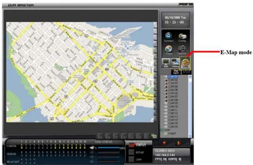
[Fig.8-24 E-Map MODE]
8-4.11.1. Addition of map
- Click the E-Map button on the DvrMaster.
- Right-click the MAP as shown in Fig.8-25 and click "Add eMap" on the pop-up window, and then the BMP files factory saved will show up (See Fig.8-26).
- Select a BMP file and click "OPEN button in Fig.8-26, and then an eMap will be saved under the MAP button.

[Fig.8-25 Add eMap]

[Fig.8-26 BMP files]
- To rename, right-click a saved eMap list and click "Rename" on the pop-up window as shown in Fig.8-27.
- To delete, right-click a saved eMap list and click "Delete eMap" on the pop-up window as shown in Fig.8-28.
- To display, double-click one of saved eMap lists. The image size of each channel will be minimized or maximized as much as you want.

Note : The eMap list that is currently displaying can't be deleted or renamed.


[Fig.8-28 Delete] [Fig.8-27 Rename]
8-4.11.2. Placement of cameras on the map
- Click one of the cameras connected to the DVR system and drag the mouse and drop on the map as shown in Fig.8-29.
![DRA MASTER 16/18/2000 Tm Drag & Drop CAMINA SENSOR RELAY OUT HOD STATUS STATUS REPLAY COPY GLOVER: 16CH 192.163.2.144 F:\$S\ 30\ KB\P[\ 0]](/content/2026/05/1084259/images/db078800184651c62a3938c8c6dce6e4d7755b8c6a5deb858fc658b5671614ac.jpg)
[Fig.8-29 Placement of Cameras on the Map]
8-4.11.3. Usage of camera position
The small squares with channel numbers on the map indicate the camera position. The blue screen represents that the corresponding camera is not connected to the DVR system.
- Double-click the image to display a full screen.
- To change the camera position, click the image and drag the mouse and drop on the map.
- Double-click the channel number(s) to hide or show the image(s).
- Place the mouse pointer on the square line and minimize or maximize the image by using sign.
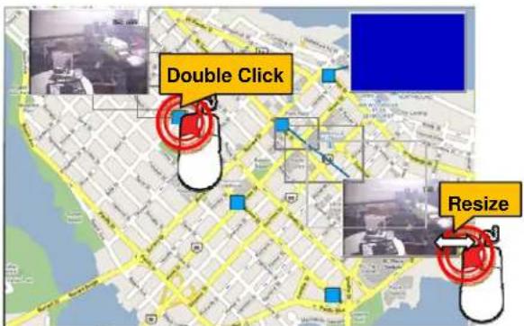
[Fig.8-30 Usage of Camera Position]
8-4.11.4. Deletion of Camera position icon
Click the image or channel number and drag the mouse and drop the mouse pointer outside of the screen.

[Fig.8-31 Deletion of Camera Position icon]
8-4.12 Pan / Tilt & Preset
You can control the PTZ camera through DvrMaster. This feature is basically identical to what the DVR system has. Refer to section 6-7.7 PAN/TILT on page 45.

[Fig.8-32 PAN / TILT]
8-5. PLAYER
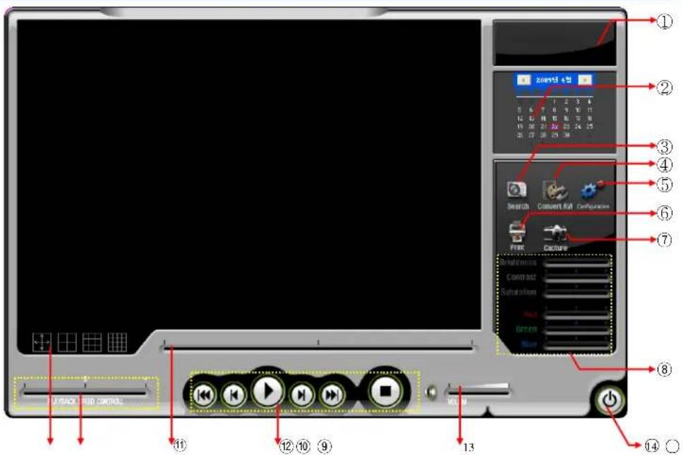
[Fig.8-33 Player]
Chart. Button of Player Program
① Status window (Play mode, Date, Time)
② Calendar
③ Search button for replaying
④ Convert to AVI File
⑤ Configuration
⑥ Print button
⑦ Capture button
⑧ Video Enhance
⑨ Division button
⑩ Playback (Replay) speed Control
⑪ Search slider for Replaying
⑫ Replay Control
⑬ Volume Control
⑭ Exit program button
① Status window (Play mode, Date, Time)
It indicates the play mode, date and time.
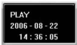
[Fig.8-34 Status window]
② Calendar
It shows the date currently being replayed.
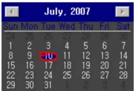
[Fig.8-35 Calendar]
④ Search button for Replaying

- Click the Search button on the Player and the Browse for Folder will be displayed.
- Select the folder that contains the recorded data and click the OK button on the Browser for Folder. One channel or all the channels can be replayed depending on the selection.
③ Convert AVI File

Convert the recorded files to AVI files.
- Click the Convert AVI button on the Player and the Convert AVI window will be displayed (See Fig.8-36.
- Click on the SELECT button for Source on the Convert AVI window and the Convert AVI window or the DVR Player will be displayed (See Fig.8-37 and Fig.8-38).
- Select the folder that contains the recorded data and select one of the channels by clicking the mouse and click the OK (See Fig.8-39).
- Click the Start Convert button on the Convert AVI window and click the CLOSE button after verifying the status "Complete" (See Fig.8-40).

[Fig.8-36 Convert AVI window]

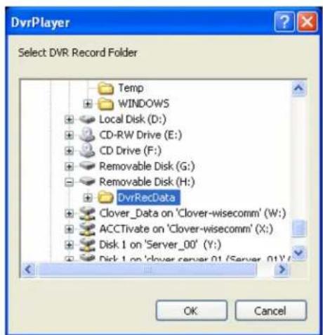
[Fig.8-37 Backup Files by Networking] [Fig.8-38 DvrRecData by USB]

[Fig.8-39 Select one of the Channels]

[Fig.8-40 Start Convert Button]
How to play the AVI files
By using Windows media player:
- Click the OPEN button on the Convert AVI window and double click one of the AVI files to play. The AVI files will save in the AVI Files folder (Open Windows Explorer – click My Computer - click the Program Files – click DvrMaster – double click one of the AVI Files).
⑤ Configuration

[Fig.8-41 Configuration window]
- If the "Fit to window" is selected in Fig.8-41, it will automatically fit to the Player window in Fig.8-33 (720x480) even though the recorded data is CIF (360x240) in the playback mode.
- If the "Open Data Folder" is clicked in Fig. 8-41, the folders relating to the DvrMaster such as the Auto Save, AVI Files, Backup Files, Emap Files, Printed Files and System Files will be displayed.
⑥ Print button

- Click the Print button when a full screen is replaying on the Player and the current images will print out along with comments if you write down some comments in the Print Comment Dialog as shown in Fig.8-42.
- Click the OK button in the Print Comment Dialog regardless of the comments to print.
⑦ Capture button
- Click the Capture button when a full screen is replaying on the Player and the current images will be saved in the Printed Files (Open Windows Explorer – click My Computer - click the Program Files – click DvrMaster – click Printed Files) in JPEG file format.

[Fig.8-42 Print command window]
![DVR IMAGE DVR : SDVR TIME : 2006-08-22 15:40:57 [COMMENT] 1CHANNEL IMAGE](/content/2026/05/1084259/images/fede730804366aaca7abb92810baf5ae13983f75546771a81dd0599200678260.jpg)
[Fig.8-43 Print image]
⑧ Video Enhance
Refer to section 6-8 on page 53.
⑨ Division button

Select one of the following divisions while replaying.

Full Screen
4 Division Screen
9 Division Screen
16 Division Screen
[Fig.8-44 Division button]
⑩ Playback (Replay) Speed Control
Move the slider with the mouse to control the replaying speed.
The "0" represents the normal speed, "-"and "+" represents slow speed and fast speed respectively.

[Fig. 8-45 Replay Speed Control Slider]
⑪ Search slider for replaying
The slider can be moved left and right by clicking the slider on the bar and dragging it or just click the bar to search the recorded data.

natural_image
Pure electrical circuit lines without any symbols[Fig.8-46 Replay Search Slider]
⑫ Replay Control
Refer to section 6-10.2.3.

flowchart
graph TD
    A["PLAY"] --> B["PREV"]
    B --> C["REW"]
    D["NEXT"] --> E["FF"]
    F["STOP"] --> G["■"]
[Fig.8-47 Replay Control buttons]
⑬ Volume Control.
Control the volume when replaying in the full screen mode

[Fig.8-48 Replay Volume Control Slider]
⑭ Exit button

Click the Exit button on the Player to exit.
APPENDIX
CONTENTS
HDD : 750GB, Based on 16 cameras
Recording Resolution : CIF(360 X 240)
DAYS
| Each CH(16CH/fps) | 30 fps(480fps) | 15 fps(240fps) | 10 fps(160fps) | 7.5 fps(120fps) | 5 fps(80fps) | 3 fps(48fps) | 2 fps(32fps) | 1 fps(16fps) |
| BEST | 18.22 | 36.44 | 54.66 | 72.88 | 109.32 | 182.20 | 273.30 | 546.60 |
| HIGH | 28.25 | 56.50 | 84.75 | 113.00 | 169.50 | 282.50 | 423.75 | 847.50 |
| NORMAL | 37.88 | 75.76 | 113.64 | 151.52 | 227.28 | 378.80 | 568.20 | 1,136.40 |
| LOW | 49.75 | 99.50 | 149.25 | 199.00 | 298.50 | 497.50 | 746.25 | 1,492.50 |
Recording Resolution : HD1(720 X 240)
| Each CH(16CH/fps) | 15 fps(240fps) | 10 fps(160fps) | 7.5 fps(120fps) | 5 fps(80fps) | 3 fps(48fps) | 2 fps(32fps) | 1 fps(16fps) | |
| BEST | 19.52 | 29.28 | 39.04 | 58.56 | 97.60 | 146.40 | 292.80 | |
| HIGH | 30.10 | 45.15 | 60.20 | 90.30 | 150.50 | 225.75 | 451.50 | |
| NORMAL | 42.72 | 64.08 | 85.44 | 128.16 | 213.60 | 320.40 | 640.80 | |
| LOW | 56.48 | 84.72 | 112.96 | 169.44 | 282.40 | 423.60 | 847.20 |
Recording Resolution : D1(720 X 480)
| Each CH(16CH/fps) | 7.5 fps(120fps) | 5 fps(80fps) | 3 fps(48fps) | 2 fps(32fps) | 1 fps(16fps) | |||
| BEST | 34.36 | 51.54 85 | 90 128 | 85 25 | 7.70 | |||
| HIGH | 46.95 | 70.43 1 | 17.38 1 | 76.06 | 352.13 | |||
| NORMAL | 62.01 | 93.02 1 | 55.03 2 | 32.54 | 465.08 | |||
| LOW | 83.33 | 125.00 | 208.33 | 312.49 | 624.98 |
DAYS
DAYS
Factory default settings
(1) LIVE SCREEN
16 SPLIT
OSD ON
(2) TIME / DATE
DISPLAY : ON
TIME FORMAT : 24 HOUR
DATE FORMAT : YYYY/MM/DD
(3) LOAD / BACKUP CONFIG
NONE LISTS
(4) USER ACCOUNT
PASSWORD : SET YOUR PASSWORD ( THE PASSWORD IS NULL )
PASSWORD ON/OFF : OFF
(5) IR REMOTE ID
OFF
(6) HDD OVERWRITE
ON
(7) CAMERA
ACTIVE : ALL ON
NAME : CAM XX
BUZZER : ALL ON
RELAY : ALL OFF
PAN/TILT VENDOR : PELCO
DISPLAY : ON
SEQ DISPLAY DWELL : 1 SEC
(8) AUDIO
AUDIO 1 : RELATED CAMERA CH 1, RECORD OFF, LEVEL 5
AUDIO 2 : RELATED CAMERA CH 2, RECORD OFF, LEVEL 5
AUDIO 3 : RELATED CAMERA CH 3, RECORD OFF, LEVEL 5
AUDIO 4 : RELATED CAMERA CH 4, RECORD OFF, LEVEL 5
AUDIO 5 : RELATED CAMERA CH 5, RECORD OFF, LEVEL 5
AUDIO 6 : RELATED CAMERA CH 6, RECORD OFF, LEVEL 5
AUDIO 7 : RELATED CAMERA CH 7, RECORD OFF, LEVEL 5
AUDIO 8 : RELATED CAMERA CH 8, RECORD OFF, LEVEL 5
(9) RECORD
RECORD ICON DISPLAY : ON
SIZE : ALL HALF D1 (704 X 240)
FPS : ALL 15 fps
QUALITY : ALL HIGH
MODE: ALL MANUAL RECORD MODES
SENSITIVITY : LOW (19)
-
TIMER RECORD
ACTIVE : ALL OFF
TIMER : ALL 00 : 00 -
MOTION
DETECT : OFF
PRE : 1 sec.
HOLD : 1 sec.
SPOT : OFF
REGION : ALL SET
- SENSOR
DETECT : OFF
PRE:1 sec.
HOLD : 1 sec.
SPOT : OFF
(10) NETWORK
TYPE : DYNAMIC
PORT : 113
I CANNOT LOGIN ....174
I can not login
▶ Please check if the link LED of DVR and LAN port of PC are lit.
▶ Please check if the IP address on DVR and the PC is identical.
Check SYSTEM STATUS by pressing STATUS button of DVR
(Available on LIVE mode and RECORD mode.)
MY IP : xxx.xxx.xxx.xxx
Check Target IP Address by clicking CONF button of PC host program.
TARGET IP ADDRESS : xxx.xxx.xxx.xxx
▶ Please check whether there is a response upon PING test with DVR IP.
Type "PING -t xxx.xxx.xxx.xxx" in DOS COMMAND window and execute.
(xxx.xxx.xxx.xxx is the DVR IP)
Request timed out → Check IP address
Reply from : xxx.xxx.xxx.xxx : Check Port number. Check if other user is using this.
▶ Please check the Port number of DVR and PC is identical.
Check Port number at MENU-SETUP → SYSTEM → NETWORK IP CONFIG.
PORT : 5800 ( on DVR )
TARGET PORT NUMBER : 5800 ( on Host Program )
▶ Please confirm the Password of DVR and PC is identical.
Check Password at MENU → SETUP → SYSTEM → PASSWORD
▶ Please check whether DVR is connected another PC.
Check SYSTEM STATUS by pressing STATUS button.
FROM : xxx.xxx.xxx.xxx : IP which is presently connected.
MY IP : xxx.xxx.xxx.xxx : DVR is waiting for connection.
▶ Please check whether firewall is installed in the network.
Ask the network administrator to reconfigure the firewall.
Limited 1 Year Warranty
This warranty gives the original purchaser specific legal rights and you may also have other rights, which may vary from state to state. If our products do not function because of any defect in material or workmanship, we will repair it for free for 1 year on parts and labor from the date of original purchase. This warranty does not cover modification, abuse, incidental or consequential damages unless the state of owner's residence specially prohibits limitations on incidental or consequential damages.
How to obtain Factory Service
- Original purchaser must fill out the warranty card and mail it to the factory with the model number, serial number and the date of purchase.
- We will repair or replace, and return the system to the owner under this limited warranty.
- Please pack the system carefully and securely using the original packing materials, and send it prepaid and insured to: 13073 E. 166th St, Cerritos, CA 90703.
- Please include a check for \$50.00 to cover the cost of return postage and handling. If the system is returned within the warranty period, please include a proof of purchase. If the system is out of warranty, you will receive an estimate of the repair cost for your approval before repair work will be started.

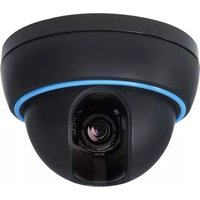
- 26" Wide LCD Screen All in One System Built-in 16Ch DVR
- CONTENTS
- ABOUT THIS MANUAL....9
- HOW TO OPERATE 29
- 7-6. RECORD.... 101
- 7-7. NETWORK....119
- 8.REMOTE HOST PROGRAM 131
- Unpacking
- 1-1. 26" Wide LCD Panel Built-in 16 Ch Digital Video Recorder
- Features
- What to do at the time of Installation
- The system should be installed in the following order;
- Specifications
- 5
- Installation
- 5-1. Controls and Connectors
- REC Key
- TALK Key
- EXIT Key
- ENTER Key
- UP Key
- DOWN Key
- Stand-by Power Mode Button
- POWER LED
- Remote Control Signal Receiver
- 5-2. Note for Installation
- 5-3. System Connection
- 5-4. Installation
- 5-4.1. Camera Connection
- 5-4.2. Installation of the Monitor
- Note:
- 5-4.2.1. Connection of Composite Monitor
- 5-4.3. Sensor Connection and RELAY IN & OUT
- - SENSOR Connection (SENSOR IN)
- - ALARM OUT Connection
- 5-4.4. RS485 Connection
- 5-4.5 Connection to an Ethernet Network (Optional)
- 5-4.6. POWER CABLE CONNECTION
- 6
- How to operate
- 6-1. General Information
- 6-2. Operating Interface
- 6-3. IR Remote Controller
- 6-4. Power On/Off
- 6-4.1. POWER ON
- 6-4.2. STAND-BY POWER MODE BUTTON
- 6-4.3. POWER OFF
- By clicking the mouse:
- 6-5. Menu Window
- 6-6. Display Screen
- 6-6.1. FULL SCREEN
- 6-6.2. SPLIT SCREENS
- 6-7. LIVE
- 6-7.1. FULL SCREEN
- 6-7.2. SPLIT SCREEN
- 6-7.3. SEQUENCING SCREENS
- 6-7.4. LIVE AUDIO
- 6-7.4.1. COMMUNICATION BETWEEN MONITOR AND CLIENT COMPUTER VIA INTERNET
- 6-7.4.2. COMMUNICATION BETWEEN MONITOR AND CAMERAS
- 6-7.5. ZOOM
- 6-7.6. OSD ON / OFF
- 6-7.7. PAN / TILT
- ▪ Channel Selection and Screen Conversion
- - ZOOM / FOCUS
- - PAN / TILT
- • IRIS
- - Button of PAN/TILT Control window
- PRESET
- Preset Setup
- Preset Execution
- 6-7.8. SYSTEM STATUS
- 6-7.9. POWER LOSS LISTS
- 6-7.10. VIDEO LOSS LIST
- 6-8. VIDEO ENHANCE
- 6-8.1. CAMERA INPUT CONFIG (CONTRAST / BRIGHTNESS)
- 6-8.2. VGA OUTPUT CONFIG (SCALE / CONTRAST / BRIGHTNESS / SATURATION)
- 6-9. Record
- 6-9.1. Manual (Continuous) recording
- 6-9.2. Manual Event Recording
- 6-9.3. Timer Recording
- 6-9.4. Timer Event Recording
- 6-9.5 Audio Recording
- 6-9.6. Estimated Recording Time
- 6-9.7. Recording Icons
- 6-10. REPLAY
- 6-10.1. QUICK REPLAY
- 6-10.2. REPLAY
- 6-10.2.1. Playback Devices
- 6-10.2.2. Set the Start Time
- By using the Replay Time set-up buttons:
- By using the Replay Time set-up bar:
- 6-10.2.3. Replaying
- 6-10.2.4. Disappearance of Replay control buttons
- 6-11. COPY
- 6-11.1. Copying devices
- In regards to blank Medias (CD-R/W and DVD-R/W)
- 6-11.2. Set the Copy Start Time (Copying extent)
- By using the Copy Start/End set-up buttons:
- By using the Start/End set-up bar:
- 6-11.3. Set the Copy End Time (Copying extent)
- 6-11.4. Copying the recorded data during replaying
- Select COPY Mode
- USB COPY
- CD-RW COPY
- DVD-RW COPY
- 6-11.5. PLAYER / AVI File Format
- Copying the Recorded data with the PLAYER
- Copying the AVI File Format
- 7
- SETUP
- 7-4. CAMERA 92
- 7-5. AUDIO 100
- 7-6. RECORD 101
- 7-1. SETUP
- 7-2. SYSTEM
- 7-2.1. SYSTEM NAME
- 7-2.2. LANGUAGE
- LANGUAGE
- : ENGLISH
- 7-2.3. TIME / DATE
- TIME FORMAT : 24 HOUR
- - DATE FORMAT
- - DATE Settings
- ▪ DISPLAY
- 7-2.4. SYSTEM CONFIG
- 7-2.4.1. FACTORY DEFAULT
- FACTORY DEFAULT : FACTORY DEFAULT
- 7-2.4.2. LOAD CONFIG / BACKUP CONFIG
- - LOAD CONFIG
- - BACKUP CONFIG
- 7-2.5. PASSWORD
- ON/OFF
- - PASSWORD CHANGE
- 7-2.6. IR REMOTE ID
- 7-2.7. FIRMWARE UPDATE
- By USB memory
- By DvrMaster (GUI)
- 7-2.8. SYSTEM INFO
- 7-3. DISK MANAGER
- 7-3.1. HDD WRITE FAIL
- 7-3.2. HDD OVERWRITE
- 7-3.3. Format
- 7-4. CAMERA
- 7-4.1. Camera ON/OFF
- 7-4.2. Camera Name (Camera Title)
- 7-4.3. Buzzer
- 7-4.4. Relay
- 7-4.5. Pan/Tilt Settings
- - Baud rate
- BAUDRATE
- BPS
- - Data Bits
- DATA BITS
- - Stop Bits
- - Parity Bit
- - PTZ ID
- 7-4.6 Display
- DISPLAY
- ON
- 7-4.7 Sequencing dwell time
- SEQUENCING DWEL TIME
- SECOND
- 7-5. AUDIO
- 7-5.1. Microphone Volume
- 7-6. RECORD
- 7-6.2. All Manual / Timer recording button
- 7-6.3. All Motion ON / OFF, Sensitivity Setting
- SENSITIVITY HIGH
- 7-6.4. All Sensors ON / OFF
- 7-6.5. Size (Recording Resolution)
- 7-6.6. Recording Speed
- 7-6.7. Recording Quality
- 7-6.8. Recording Mode
- 7-6.8.1. Manual Recording
- 7-6.8.2. Manual Event Recording
- 7-6.8.3. Timer Recording (Schedule Recording)
- 7-6.8.4. Timer Event Recording
- 7-6.9. Recording by Motion Detection
- PRE
- 2
- SECOND
- HOLD
- 3
- SPOT
- OFF
- EXIT
- By All Set
- By Window Set
- - Window Clear
- By Each Cell
- - Buzzer
- BUZZER
- 7-6.10. Recording by Sensor (PIR Sensor)
- - ON/OFF
- - Pre-Alarm Time Setup
- - Alarm Hold Time Setup
- SECOND
- - Spot Setup
- 7-7. NETWORK
- 7-7.1. IP Mode
- 7-7.2. GATEWAY, SUBNET, IP ADDRESS
- 7-7.3. Port
- 7-7.3.1 Port Forwarding
- 7-7.4. MAC ID
- 7-7.5. MNS (MAC NAME SERVER)
- - DISABLE / ENABLE
- 7-7.6. DDNS (DYNAMIC DOMAIN NAME SYSTEM)
- "SERVER
- SERVER
- DYNDNS.ORG
- - HOST NAME
- HOST NAME
- DVR.DYNDNS.ORG
- - USER ID
- USER ID
- USER
- - PASSWORD
- PASSWORD
- 7-7.7. HOW TO SETUP AND USE THE DDNS
- 7-7.7.1. Router.
- 7-7.7.2. Registration to the DDNS server
- Registration to DYNDNS.ORG
- 7-7.8. EMAIL NOTIFICATION
- - EVENT Setup
- - INTERVAL TIME Setup
- 8
- Remote Host Program
- 8-1. Remote Program Overview
- Remote system minimum requirements
- 8-2. Installing the Program to PC
- How to install the program
- How to set Screen Resolution and Color Quality
- 8-3. Internet Explorer
- How to setup the Internet Explorer
- 8-4.1. Setup
- 8-4.2. Connection
- 8-4.3. Capture
- 8-4.4. Status
- STATUS
- 8-4.5. Replay
- - Playback Control
- Playback control buttons
- 8-4.6. COPY
- COPY
- 8-4.7. Switch the Normal Screen to Full Screen
- 8-4.8. Speaker / Microphone
- Buttons of Remote Host Program
- 8-4.9. Connection mode
- 8-4.9.1. Terminal mode
- 8-4.9.2. Multi mode
- 8-4.10. Copy in the Terminal mode
- 8-4.11 E-Map
- 8-4.11.1. Addition of map
- 8-4.11.2. Placement of cameras on the map
- 8-4.11.3. Usage of camera position
- 8-4.11.4. Deletion of Camera position icon
- 8-4.12 Pan / Tilt & Preset
- Chart. Button of Player Program
- How to play the AVI files
- ⑤ Configuration
- ⑥ Print button
- ⑦ Capture button
- APPENDIX
- Factory default settings
- LIVE SCREEN
- TIME / DATE
- LOAD / BACKUP CONFIG
- USER ACCOUNT
- IR REMOTE ID
- HDD OVERWRITE
- CAMERA
- AUDIO
- RECORD
- NETWORK
- I can not login
- Limited 1 Year Warranty
- How to obtain Factory Service
Brand : Clover Electronics
Model : LCD26164
Category : Screen