
PSS2536B - Flat Panel Mount Chief - Free user manual and instructions
Find the device manual for free PSS2536B Chief in PDF.


| Product Type | Flat Panel Mounting Bracket |
| Brand | Chief |
| Model | PSS2536B |
| Maximum Load Capacity | 175 lbs (79.38 kg) |
| Installation Type | Fixed, attaches to existing Chief mount |
| Weight of Mount | Not specified |
| Material | Steel |
| Color | Black |
| Included Components | 2 Side Brackets, 2 Top/Bottom Brackets, 4 Mounting Buttons, 8 10-24 x 0.5 in Button Head Cap Screws, 4 M8 x 35 mm Button Head Cap Screws, 4 M8 x 50 mm Button Head Cap Screws, 4 Nylon Spacers (0.51 x 0.32 x 0.875 in), 4 Nylon Spacers (0.68 x 0.32 x 0.625 in), 1/8 in Allen Key, M5 Allen Key |
| Required Tools | Allen keys (included) |
| Assembly Required | Yes |
| Installation Support | Professional installation recommended; requires structural member capable of supporting 4x combined weight |
| Safety Compliance | UL listed; must secure to structural member |
| Compatibility | Designed for use with Chief mounts (sold separately) |
| Display Fragility | Caution: displays are extremely fragile; two-person lift required |
| Mounting Pattern | Universal mounting holes with spacers for various display back configurations |
| Tilt / Swivel | Not applicable (fixed mount) |
| Maintenance | Wipe clean with a dry, soft cloth |
| Warranty | Refer to Chief warranty policy |
| Customer Service | 1-800-582-6480 (for missing parts) |
Frequently Asked Questions - PSS2536B Chief
User questions about PSS2536B Chief
0 question about this device. Answer the ones you know or ask your own.
Ask a new question about this device
Download the instructions for your Flat Panel Mount in PDF format for free! Find your manual PSS2536B - Chief and take your electronic device back in hand. On this page are published all the documents necessary for the use of your device. PSS2536B by Chief.
USER MANUAL PSS2536B Chief
INSTALLATION INSTRUCTIONS
PSB-2534 & 2536
DISPLAY MOUNTING BRACKET ^UL
Prior to assembly, unpack carton completely and verify contents.
If you are missing any of the following components, please contact Customer Service at 1-800/582-6480

natural_image
Pure electrical circuit lines without any symbols(2) Plasma Side Bracket (2) Plasma Top/Bottom Bracket
(4) Mounting Button - Tapped (8) 10-24 x .5 Button Head Cap Screw
(4) M8 x 35mm Button Head Cap Screw (4) .51 X .32 X .875 Nylon Spacer
(4) M8 x 50mm Button Head Cap Screw (4).68 X .32 X .625
(1) 1/8 Allen Key (1) M5 Allen Key
BEFORE PROCEEDING, READ INSTALLATION INSTRUCTIONS COMPLETELY
CAUTION!
DISPLAYS ARE EXTREMELY FRAGILE.
WARNING!
ALL COMPONENTS MUST BE SECURELY FASTENED TO A STRUCTURAL MEMBER CAPABLE OF SUPPORTING 4 TIMES THE COMBINED WEIGHT OF ALL COMPONENTS PLUS THE EQUIPMENT BEING MOUNTED. IF IT CANNOT SUPPORT THIS WEIGHT, THE STRUCTURE MUST BE REINFORCED.
THE MAXIMUM WEIGHT TO BE INSTALLED ON THE MOUNT IS 175 POUNDS (79.38 KG).
- Using a 10-24 button head cap screw inserted from back side of bracket, secure mounting button, with chamfered hole of mounting button (larger surface) facing bracket, to top and bottom brackets (four places) (see Figure 2 & Figure 3).
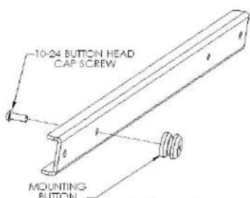
Figure 2 Figure 3

flowchart
graph TD
    A["●"] --> B["○"]
    C["○"] --> D["○"]
    E["○"] --> F["○"]
    G["○"] --> H["○"]
    I["○"] --> J["○"]
    K["○"] --> L["○"]
    M["○"] --> N["○"]
    O["○"] --> P["○"]
    Q["○"] --> R["○"]
    S["○"] --> T["○"]
    U["○"] --> V["○"]
    W["○"] --> X["○"]
    Y["○"] --> Z["○"]
    AA["○"] --> AB["○"]
    AC["○"] --> AD["○"]
    AE["○"] --> AF["○"]
    AG["○"] --> AH["○"]
    AI["○"] --> AJ["○"]
    AK["○"] --> AL["○"]
- Using four 10-24 button head cap screws, attach top and bottom to side brackets (see Figure 4 & Figure 5). The square offset holes can be used if use of the center hole causes the cross brackets to block connections or if an offset is needed for the installation (See Figure 6 & Figure 7).
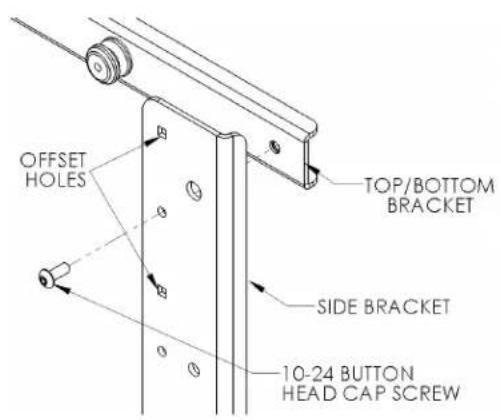
Figure 4 Figure 5
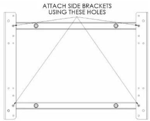
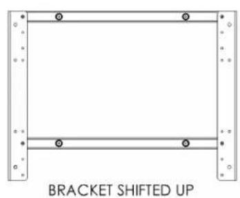
Figure 6 Figure 7

natural_image
Simple diagram of a bracket with a horizontal line and circular markers, labeled 'BRACKET SHIFTED DOWN' below (no other text or symbols)-
Place Nylon spacers over mounting holes on back of screen. Attach mounting brackets to display using M8 screws (see Figures 8 & Figure 9). If needed add both sets of spacers and use the set of longer bolts to attain required clearance.
-
With the aid of another person, lift your display up to the Chief Mount, aligning buttons of mounting brackets with slots in the Chief Mount.
-
Lower safety latch on the Chief Mount to secure your display, making sure latch is completely engaged.

Figure 8

Figure 9
Brand : Chief
Model : PSS2536B
Category : Flat Panel Mount