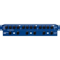
Catapult Rack TX - Audio Equipment Radial Engineering - Free user manual and instructions
Find the device manual for free Catapult Rack TX Radial Engineering in PDF.


| Product Type | Audio over IP Transmitter |
| Model | Catapult Rack TX |
| Brand | Radial Engineering |
| Form Factor | 1U Rackmount |
| Dimensions (WxDxH) | 19 x 8 x 1.75 in (483 x 203 x 44 mm) |
| Weight | 5.5 lbs (2.5 kg) |
| Power Supply | External 48V DC or PoE+ (802.3at) |
| Audio Input | 2 x Balanced XLR (combo) |
| Audio Output | 1 x RJ45 Ethernet (Dante/AES67) |
| Sample Rates | 44.1 kHz, 48 kHz, 96 kHz |
| Bit Depth | 16, 24 bit |
| Latency | < 1 ms (Dante) |
| Phantom Power | +48V switchable per channel |
| Frequency Response | 20 Hz – 20 kHz (±0.5 dB) |
| Dynamic Range | > 110 dB (A-weighted) |
| THD+N | < 0.001% |
| Controls | Gain knobs, phantom switches, LED indicators |
| Operating Temperature | 0°C to 40°C (32°F to 104°F) |
| Mounting | 19" rack ears with screws |
| Safety | Use only supplied PSU; do not expose to rain or moisture |
| Maintenance | Clean with dry, lint-free cloth; no user-serviceable parts |
| Repairability | Contact Radial Engineering for service |
| Included Accessories | Power supply, rack ears, rubber feet, quick start guide |
Frequently Asked Questions - Catapult Rack TX Radial Engineering
User questions about Catapult Rack TX Radial Engineering
0 question about this device. Answer the ones you know or ask your own.
Ask a new question about this device
Download the instructions for your Audio Equipment in PDF format for free! Find your manual Catapult Rack TX - Radial Engineering and take your electronic device back in hand. On this page are published all the documents necessary for the use of your device. Catapult Rack TX by Radial Engineering.
USER MANUAL Catapult Rack TX Radial Engineering
CATAPULT RACK TX & RX
CAT 5 ANALOG AUDIO SNAKE

natural_image
Front view of a blue GATAPLAT 83 network interface with multiple ports and connectors (no visible text or symbols on the device body)User Guide
Radial Engineering Ltd.
1165-1845 Kingsway Ave, Port Coquitlam
British Columbia, Canada, V3C 0H3
Tel: 604-942-1001 • www.radialeng.com
Email: info@radialeng.com
Radial® Reamp Station User Guide
Table of Contents Page
Overview....1
Features 2-3
Making Connections....4
Lifting the Ground....5
Using the Catapult TX and RX as a Pair 5
The Radial Catapult Family 6
Additional Applications.... 7-8
Specifications 9
Warranty ....Back cover
Thank you for purchasing the Radial Catapult™ Rack modular snake, a Cat 5 analog audio snake system that is designed to simplify stage setups, take advantage of pre-existing wire infrastructure, and work in combination with other Catapult modules.
We recommend you take a few minutes to read this short manual before you begin using the Catapult Rack TX or RX, as it covers the various features of these devices and tips for setup and use. Should you have any questions about the Catapult Rack or any other Radial Catapult modules, please visit our website at www.radialeng.com for additional resources and frequently asked questions.
OVERVIEW
The Catapult Rack TX and RX both act like typical multi-channel analog audio snakes; they allow you to send balanced mic or line-level signals from one location to another without signal loss, noise, or interference, and without any digital audio conversion needed. However, unlike typical analog snakes that require bulky and expensive multi-channel audio cables, the Catapult system makes use of Cat 5 Ethernet cabling, which is widely available, lightweight, and economical.
Simply connect one shielded Cat 5 cable for every four channels of audio and deliver it to any other Radial Catapult module – it will utilize the analog conductors in the cable to deliver four balanced audio lines to any destination. As many buildings are already pre-wired for Cat 5, you can take advantage of this to transmit audio between distant rooms without the need to install or supply new cable. And since the Catapult system is modular, you can mix and match different transmit and receive boxes to best suit your application.
Each Catapult Rack unit operates like three separate Catapult modules in one chassis. The 12 XLRs on the chassis are split into three banks, each with their own noise-eliminating ground lift switch and RJ45 Ethernet jacks on the rear panel. You can use three Ethernet cables to connect all 12 channels to a single location, or split them off to any of the Radial Catapult stage boxes, providing you with a fully customizable audio snake system that can connect to multiple destinations at once. The Catapult Rack TX features all female XLR connectors, while the Catapult Rack RX has 12 male XLR connectors.
The Catapult Rack TX

natural_image
Front and back view of a CATAPULT 3D audio workstation rack with multiple ports (no visible text or labels beyond branding)The Catapult Rack RX

natural_image
Front and back view of a CATAPULT 22 network interface with multiple ports (no readable text or symbols beyond labels)FEATURES - CATAPULT RACK TX

-
GROUND LIFT: Lifts pin-1 on all four of the corresponding XLR connectors to remove hum and buzz caused by ground loops.
-
XLR INPUTS: Locking female XLRs are provided in banks of four, each bank corresponds to a pair of rear panel RJ45 connectors to transmit analog audio over Cat 5 cabling.
-
REVERSIBLE RACK EARS: Can be placed on either side of the Catapult Rack, allowing for the XLRs or the RJ45 connectors to face outwards for added flexibility.
-
RJ45 OUTPUT AND THRU: Standard Ethernet style connectors for feeding four channels of audio to another Catapult module. Both connectors are wired in parallel with the front panel XLRs. Rugged Neutrik etherCON jacks provide a robust connection for live touring use.
FEATURES - CATAPULT RACK RX

- GROUND LIFT: Lifts pin-1 on all four of the corresponding XLR connectors to remove hum and buzz caused by ground loops.
- XLR OUTPUTS: Locking male XLRs are provided in banks of four, each bank corresponds to a pair of rear panel RJ45 connectors to receive analog audio over Cat 5 cabling.
- REVERSIBLE RACK EARS: Can be placed on either side of the Catapult Rack, allowing for the XLRs or the RJ45 connectors to face outwards for added flexibility.
- RJ45 INPUT AND THRU: Standard Ethernet style connectors for receiving four channels of audio from another Catapult module. Both connectors are wired in parallel with the front panel XLRs. Rugged Neutrik etherCON jacks provide a robust connection for live touring use.
MAKING CONNECTIONS
As with all audio systems, it is good practice to turn volume levels down or audio systems off before making connections to and from the Catapult Rack. This will help avoid connection or power-up transients from damaging more sensitive components such as tweeters.
You can use any standard Cat 5 or Cat 6 cable to connect Catapult Rack units to each other or to any other Radial Catapult modules. In order to pass 48V phantom power to feed your condenser mics or active direct boxes, the cable and terminating connections must have a shield.
If you are transmitting line level signals, the shield is not required due to the twisted pair configuration, but it will still be beneficial as shielded cables are less susceptible to noise. As the twisted pairs in a Cat 5 cable are tightly wound together in a compact jacket, it's a good idea to send similar level signals together over the same wire as this will reduce crosstalk from higher signal levels (such as +4dB line levels) bleeding onto lower output signals (such as -30dB mic levels).

natural_image
Two types of Ethernet connectors shown: one with yellow cable and another with a black cable (no text or symbols visible)A typical Cat 5 connector and cable showing the four twisted pairs
The Catapult Rack also supports the use of a ruggedized and lockable RJ45 connector type known as an etherCON connector, which features a metal shell that surrounds and protects the RJ45 plug, and prevents against accidental disconnection.

natural_image
Close-up of two black circular electronic components with mounting holes, labeled 'A' (no text or symbols on the components themselves)The Catapult Rack RJ45 connectors

natural_image
Close-up of a black USB cable connector (no text or symbols visible)A Neutrik etherCON connector
Each Catapult Rack has two RJ45 connectors for each bank of four XLRs. One of these jacks is intended to be used as a passthrough connector which allows you to feed that bank to an additional destination. Since these jacks are wired in parallel with each other, it doesn't matter which one you use for the passthrough - this is why they are unlabeled.
LIFTING THE GROUND
Each bank of four channels on the Catapult Rack is equipped with a ground lift switch. Start with this switch set to the 'out' position.
If you hear noise on one of the banks after you have connected to your source and destination devices, try engaging this switch as it can help eliminate ground loop noise such as hum and buzz.
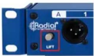
The ground lift switch
However, note that lifting the ground will disconnect phantom power, which means that condenser mics or active DI boxes will not work on that bank of channels.
USING THE CATAPULT RACK TX AND RX AS A PAIR
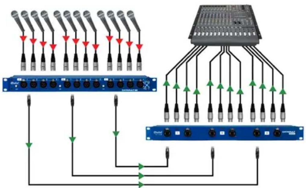
To use the Catapult Rack units in their simplest form, connect the TX to the RX using three Cat 5 cables. This creates a 12 channel rackmount audio snake that allows you to send balanced mic or line-level signals from one distant location to another.
flowchart
graph TD
    A["Audio Module 1"] -->|Red Arrow Down| B["Signal Line"]
    C["Audio Module 2"] -->|Red Arrow Up| B
    D["Audio Module 3"] -->|Red Arrow Down| B
    E["Audio Module 4"] -->|Red Arrow Up| B
    F["Audio Module 5"] -->|Red Arrow Down| B
    G["Audio Module 6"] -->|Red Arrow Up| B
    H["Audio Module 7"] -->|Red Arrow Down| B
    I["Audio Module 8"] -->|Red Arrow Up| B
    J["Audio Module 9"] -->|Red Arrow Down| B
    K["Audio Module 10"] -->|Red Arrow Up| B
    L["Audio Module 11"] -->|Red Arrow Down| B
    M["Audio Module 12"] -->|Red Arrow Up| B
    N["Audio Module 13"] -->|Red Arrow Down| B
    O["Audio Module 14"] -->|Red Arrow Up| B
    P["Audio Module 15"] -->|Red Arrow Down| B
    Q["Audio Module 16"] -->|Red Arrow Up| B
    R["Audio Module 17"] -->|Red Arrow Down| B
    S["Audio Module 18"] -->|Red Arrow Up| B
    T["Audio Module 19"] -->|Red Arrow Down| B
    U["Audio Module 20"] -->|Red Arrow Up| B
    V["Audio Module 21"] -->|Red Arrow Down| B
    W["Audio Module 22"] -->|Red Arrow Up| B
    X["Audio Module 23"] -->|Red Arrow Down| B
    Y["Audio Module 24"] -->|Red Arrow Up| B
    Z["Audio Module 25"] -->|Red Arrow Down| B
    AA["Audio Module 26"] -->|Red Arrow Up| B
    AB["Audio Module 27"] -->|Red Arrow Down| B
    AC["Audio Module 28"] -->|Red Arrow Up| B
    AD["Audio Module 29"] -->|Red Arrow Down| B
    AE["Audio Module 30"] -->|Red Arrow Up| B
    AF["Audio Module 31"] -->|Red Arrow Down| B
    AG["Audio Module 32"] -->|Red Arrow Up| B
    AH["Audio Module 33"] -->|Red Arrow Down| B
    AI["Audio Module 34"] -->|Red Arrow Up| B
    AJ["Audio Module 35"] -->|Red Arrow Down| B
    AK["Audio Module 36"] -->|Red Arrow Up| B
    AL["Audio Module 37"] -->|Red Arrow Down| B
    AM["Audio Module 38"] -->|Red Arrow Up| B
    AN["Audio Module 39"] -->|Red Arrow Down| B
    AO["Audio Module 40"] -->|Red Arrow Up| B
    AP["Audio Module 41"] -->|Red Arrow Down| B
    AQ["Audio Module 42"] -->|Red Arrow Up| B
    AR["Audio Module 43"] -->|Red Arrow Down| B
    AS["Audio Module 44"] -->|Red Arrow Up| B
    AT["Audio Module 45"] -->|Red Arrow Down| B
    AU["Audio Module 46"] -->|Red Arrow Up| B
    AV["Audio Module 47"] -->|Red Arrow Down| B
    AW["Audio Module 48"] -->|Red Arrow Up| B
    AX["Audio Module 49"] -->|Red Arrow Down| B
    AY["Audio Module 50"] -->|Red Arrow Up| B
THE RADIAL CATAPULT FAMILY
natural_image
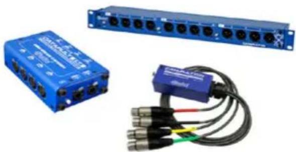
Blue industrial electronic device with multiple ports and a blue cable with three leads (no visible text or symbols)While the Catapult Rack TX and RX work great as a pair, they are made even more useful by the wide variety of other Radial Catapult modules that already exist. Since all Catapult modules are compatible with one another, you can easily customize your stage or recording studio setup to best suit your needs.
The Catapult Mini modules are extremely compact stage boxes that feature an RJ45 jack on the chassis and a 2ft long fanout of either XLR male, XLR female or TRS connectors. These units are small enough to fit inside the doghouse of a mixing console or tucked behind an equipment rack, but also rugged enough to be placed on a live stage.

The Catapult TX4 and RX4 are extremely heavy-duty stage boxes that feature both XLR and RJ45 pass thru connectors on each unit, and certain models also offer transformer isolation on each channel to keep noise to a minimum when used to connect between multiple powered devices.
The Catapult TX4M and RX4M models each feature transformers optimized for use with mic-level signals, while the TX4L and RX4L have line-level transformers on board. The standard TX4 and RX4 models do not feature transformer isolation and as such they can be used with both mic and line-level signals.

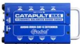
The Catapult TX4 The Catapult RX4
ADDITIONAL APPLICATIONS
The following examples demonstrate some of the various setups that are possible when using different combinations of Radial Catapult modules.
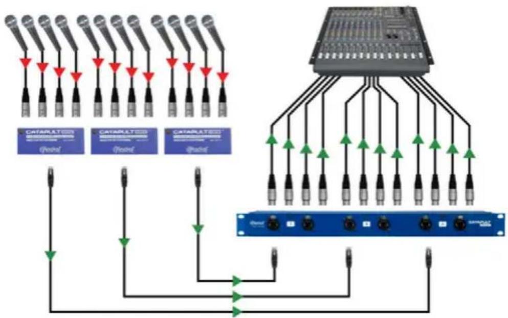
CREATE STAGE ZONES WITH MULTIPLE MODULES
Set the Catapult Rack RX at your PA console and place three compact Catapult Mini TX units at different zones on stage. This cuts down on cable clutter and streamlines your setups and teardowns.
flowchart
graph TD
    subgraph Left_Circuit
        A1["9 MHz"] --> B1["9 MHz"]
        A2["9 MHz"] --> B2["9 MHz"]
        A3["9 MHz"] --> B3["9 MHz"]
        A4["9 MHz"] --> B4["9 MHz"]
        A5["9 MHz"] --> B5["9 MHz"]
        A6["9 MHz"] --> B6["9 MHz"]
        A7["9 MHz"] --> B7["9 MHz"]
        A8["9 MHz"] --> B8["9 MHz"]
        A9["9 MHz"] --> B9["9 MHz"]
    end

    subgraph Right_Circuit
        C1["CATARAT/PSNR"] --> D1["9 MHz"]
        C2["CATARAT/PSNR"] --> D2["9 MHz"]
        C3["CATARAT/PSNR"] --> D3["9 MHz"]
        C4["CATARAT/PSNR"] --> D4["9 MHz"]
        C5["CATARAT/PSNR"] --> D5["9 MHz"]
        C6["CATARAT/PSNR"] --> D6["9 MHz"]
        C7["CATARAT/PSNR"] --> D7["9 MHz"]
        C8["CATARAT/PSNR"] --> D8["9 MHz"]
        C9["CATARAT/PSNR"] --> D9["9 MHz"]
    end

    Left_Circuit --> Right_Circuit
    style Left_Circuit fill:#f9f,stroke:#333
    style Right_Circuit fill:#bbf,stroke:#333
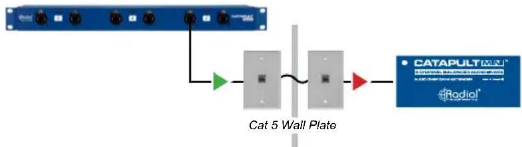
TAKE ADVANTAGE OF PRE-EXISTING CAT 5 WIRING
Use the Cat 5 cables already wired throughout a building to send audio from one room to the other without additional installation or messy cables. Keep in mind that it is common for cable infrastructure to be unshielded, so it may not pass phantom power. Note that the signals between two Catapult modules cannot pass through a network switch, as it will block the analog audio signal.
flowchart
graph LR
    A["Cat 5 Wall Plate"] --> B["CATAPULT MINI"]
    B --> C["eRadiol"]
    style A fill:#f9f,stroke:#333
    style B fill:#bbf,stroke:#333
    style C fill:#dfd,stroke:#333
ADD FLEXIBILITY WITH THE CATAPULT TX4
Combining the Catapult Rack RX with Catapult TX4 stage boxes adds flexibility to match the needs of any setup. The TX4 features both male and female XLR connectors so they can be used for both sends and returns, or the XLR thru connectors can feed channels to a monitor console while the Cat 5 cable feeds the main PA system.

flowchart
graph TD
    A["Audio Device"] --> B["Audio Amplifier"]
    B --> C["Audio Headset"]
    C --> D["Audio Receiver"]
    D --> E["Audio Mouse"]
    E --> F["Audio Headset"]
    F --> G["Audio Mouse"]
    G --> H["Audio Headset"]
    H --> I["Audio Mouse"]
    I --> J["Audio Headset"]
    J --> K["Audio Mouse"]
    K --> L["Audio Headset"]
    L --> M["Audio Mouse"]
    M --> N["Audio Headset"]
    N --> O["Audio Mouse"]
    O --> P["Audio Headset"]
    P --> Q["Audio Mouse"]
    Q --> R["Audio Headset"]
    R --> S["Audio Mouse"]
    S --> T["Audio Headset"]
    T --> U["Audio Mouse"]
    U --> V["Audio Headset"]
    V --> W["Audio Mouse"]
    W --> X["Audio Headset"]
    X --> Y["Audio Mouse"]
USE THE CATAPULT RACK WITH ISOLATED STAGE BOXES
Send audio to three separate zones by using the Catapult Rack TX and the transformer-isolated Catapult RX4L modules together as a return snake. The isolated outputs allow you to send audio to multiple power amps or other powered devices without the need to worry about ground loop noise.

flowchart
graph TD
    A["Switch"] --> B["Data 1"]
    A --> C["Data 2"]
    A --> D["Data 3"]
    B --> E["Audio 1"]
    B --> F["Audio 2"]
    C --> G["Audio 3"]
    C --> H["Audio 4"]
    D --> I["Audio 5"]
    D --> J["Audio 6"]
    E --> K["Output"]
    F --> L["Output"]
    G --> M["Output"]
    H --> N["Output"]
    I --> O["Output"]
    J --> P["Output"]
SPECIFICATIONS\*
TX - RX
Audio Circuit Type: ......Passive RJ45 to XLR
Frequency Response: 10Hz - 100kHz, ±0.05dB
Total Harmonic Distortion: ....<0.0003% @ +4dBu, 20Hz - 20kHz
Signal to Noise Ratio: ....>114dB
Dynamic Range: 136dB
Maximum Input:....+20dBu
Crosstalk Between Channels: -130dB @ 1kHz, +4dBu
Crosstalk Between Banks:....-140dB @ 1kHz, +4dBu
Features
Input / Output Connectors ....12 XLR, 6 RJ45 etherCON
Reversible Rack Ears:....Rackmount with either side facing out
Ground Lift Switch: ......Disconnects Pin-1 on bank of XLR connectors
General
Construction: 18-gauge Steel Chassis, 12-gauge Steel Faceplate
Size: L: 19" x H: 1.75" x D: 3.25"
Weight: 3.06lbs (1.39kg)
Finish: Durable Powder Coat
Warranty: Radial 3-year, transferable
THREE YEAR TRANSFERABLE LIMITED WARRANTY
RADIAL ENGINEERING LTD. ("Radial") warrants this product to be free from defects in material and workmanship and will remedy any such defects free of charge according to the terms of this warranty. Radial will repair or replace (at its option) any defective component(s) of this product (excluding finish and wear and tear on components under normal use) for a period of three (3) years from the original date of purchase. In the event that a particular product is no longer available, Radial reserves the right to replace the product with a similar product of equal or greater value. In the unlikely event that a defect is uncovered, please call 604-942-1001 or email support@radialeng.com to obtain an RA number (Return Authorization number) before the 3 year warranty period expires. The product must be returned prepaid in the original shipping container (or equivalent) to Radial or to an authorized Radial repair center and you must assume the risk of loss or damage. A copy of the original invoice showing date of purchase and the dealer name must accompany any request for work to be performed under this limited and transferable warranty. This warranty shall not apply if the product has been damaged due to abuse, misuse, misapplication, accident or as a result of service or modification by any other than an authorized Radial repair center.
THERE ARE NO EXPRESSED WARRANTIES OTHER THAN THOSE ON THE FACE HEREOF AND DESCRIBED ABOVE. NO WARRANTIES WHETHER EXPRESSED OR IMPLIED, INCLUDING BUT NOT LIMITED TO, ANY IMPLIED WARRANTIES OF MERCHANTABILITY OR FITNESS FOR A PARTICULAR PURPOSE SHALL EXTEND BEYOND THE RESPECTIVE WARRANTY PERIOD DESCRIBED ABOVE OF THREE YEARS. RADIAL SHALL NOT BE RESPONSIBLE OR LIABLE FOR ANY SPECIAL, INCIDENTAL OR CONSEQUENTIAL DAMAGES OR LOSS ARISING FROM THE USE OF THIS PRODUCT. THIS WARRANTY GIVES YOU SPECIFIC LEGAL RIGHTS, AND YOU MAY ALSO HAVE OTHER RIGHTS, WHICH MAY VARY DEPENDING ON WHERE YOU LIVE AND WHERE THE PRODUCT WAS PURCHASED.
To meet the requirements of California Proposition 65, it is our responsibility to inform you of the following:
WARNING: This product contains chemicals known to the State of California to cause cancer, birth defects or other reproductive harm.
Please take proper care when handling and consult local government regulations before discarding.

Made in Canada

www.radialeng.com
Radial Engineering Ltd.
1165-1845 Kingsway Ave, Port Coquitlam, British Columbia, V3C 0H3
Tel: 604-942-1001 • www.radialeng.com • info@radialeng.com

- CATAPULT RACK TX & RX
- User Guide
- Radial® Reamp Station User Guide
- Table of Contents Page
- OVERVIEW
- FEATURES - CATAPULT RACK TX
- MAKING CONNECTIONS
- LIFTING THE GROUND
- USING THE CATAPULT RACK TX AND RX AS A PAIR
- THE RADIAL CATAPULT FAMILY
- ADDITIONAL APPLICATIONS
- CREATE STAGE ZONES WITH MULTIPLE MODULES
- TAKE ADVANTAGE OF PRE-EXISTING CAT 5 WIRING
- ADD FLEXIBILITY WITH THE CATAPULT TX4
- USE THE CATAPULT RACK WITH ISOLATED STAGE BOXES
- SPECIFICATIONS\*
- TX - RX
- Features
- General
- THREE YEAR TRANSFERABLE LIMITED WARRANTY
Brand : Radial Engineering
Model : Catapult Rack TX
Category : Audio Equipment