SB16S - Storage Server Speco Technologies - Free user manual and instructions
Find the device manual for free SB16S Speco Technologies in PDF.


| Product Type | HD Bullet Security Camera |
| Image Sensor | 1/2.7" CMOS |
| Resolution | 1920 x 1080 (2MP) |
| Lens | 3.6mm fixed lens |
| IR Distance | 30m (98ft) |
| Day/Night Mode | Yes, with ICR filter |
| Video Output | CVBS (BNC) / AHD / TVI / CVI switchable |
| Power Supply | 12V DC, 500mA |
| Power Consumption | <6W |
| Dimensions (H x D) | 70mm x 180mm (2.76" x 7.09") |
| Weight | 0.5kg (1.1lbs) |
| Housing | Metal with weatherproof rating |
| Ingress Protection | IP66 |
| Operating Temperature | -20°C to +50°C (-4°F to 122°F) |
| Mounting | Wall or ceiling mount bracket included |
| Signal System | NTSC / PAL |
| Sync System | Internal |
| Horizontal Resolution | 1080TVL |
| Min. Illumination | 0.01 lux (color), 0.001 lux (B/W) |
| S/N Ratio | >50dB |
| Maintenance | Clean lens with soft dry cloth; check connections periodically |
| Spare Parts Availability | Power adapter, mounting kit, BNC cable (contact dealer) |
Frequently Asked Questions - SB16S Speco Technologies
User questions about SB16S Speco Technologies
0 question about this device. Answer the ones you know or ask your own.
Ask a new question about this device
Download the instructions for your Storage Server in PDF format for free! Find your manual SB16S - Speco Technologies and take your electronic device back in hand. On this page are published all the documents necessary for the use of your device. SB16S by Speco Technologies.
USER MANUAL SB16S Speco Technologies
natural_image
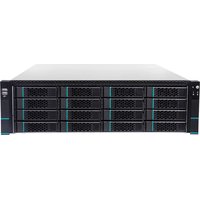
Front view of a server rack with multiple drive bays and ventilation grilles (no visible text or labels)Notes
There may be several technically incorrect places or printing errors in this manual. The updates will be added into the new version of this manual. The contents of this manual are subject to change without notice.
This manual is suitable for 16/24-disk storage servers. All the pictures used in this manual are based on the 16-disk storage server. Please refer to the real servers as the pictures may be different from the real servers.
The storage server is mainly used with Speco Blue VMS. This manual only introduces its system setup. Please refer to the storage server chapter in the Speco Blue VMS user manual for detailed use.
Contents
1 Installation .... 1
1.1 Interfaces and Indicators....1
1.2 Rear Panel Instruction .... 1
1.3 HDD Installation 2
2 Default System Configuration .... 2
3 Web Client Configuration....3
3.1 Login 3
3.2 Disk RAID .... 3
3.3 Network Configuration....4
3.4 Server Port Configuration....5
3.5 Change Password 6
3.6 Basic Information....6
3.7 Date & Time....6
3.8 Upgrade....7
3.9 Device Reboot & Shutdown....7
3.10 Restore Factory Settings....7
3.11 HTTPS Configuration 7
3.12 Debug Mode....8
3.13 Operation Log 8
4 Q&A....8
Appendix Device Installation....9
1 Installation
1.1 Interfaces and Indicators
The icons below are for reference only. Please refer to the interfaces and indicators of the real server.
| Icon | Description | Icon | Description |
 | Power Key | [2DBA] | System disk running indicator; flashing green light indicators the disk works normally. |
| [7502] | Reset | [305A] | Error Alarm indicator (including system/fan/power error alarm) |
 | USB interface | [5268] | Network connection indicator. Green light indicators the network connection is normal. |
1.2 Rear Panel Instruction
The following picture of rear panel is for reference only.

| No. | Description | No. | Description |
| 1 | Redundant Power Connector | 4 | RJ45 interface |
| 2 | RS232 interface | 5 | Management interface |
| 3 | VGA interface | 6 | USB3.1 interface |
1.3 HDD Installation

① Press the blue button, hold the pull rod to pull out the HDD case and then install the HDD into the case.
② Fix the HDD by tightening the screws on both side of the case.
③ Push the case with the HDD into the slot.
④ Fasten the pull rod.
2 Default System Configuration
The default network configurations of the server are as follows:
IP Address: 192.168.0.10
Http Port: 8000
To avoid IP conflict you should configure one at a time as these storage servers have the same default network configuration.
The default web management page: http://192.168.0.10:8000.
The default username is admin and the default password is 1234.
The disks installed in one storage server used for RAID should be of the same brand, capacity, rotate speed and buffer. The production batch should also try to be the same.
3 Web Client Configuration
3.1 Login
The storage server is configured through web browser. It is recommended to use IE9 or above, Firefox 51 or lower or Google Chrome44 or lower or Opera35 or lower (Here we take IE browser for example).
Make sure the IP address of the computer is in the same local area network with the storage server before accessing the storage server, or you will have to modify the IP address of the computer. For instance, change the computer's IP address to 192.168.0.100 and the gateway to 192.168.0.1.
Enter http://192.168.0.100:8000 in the IE address bar and then press enter to go to the login interface as shown below.

Enter the username admin and password 1234 and then click "Login" button to go to the main interface.
3.2 Disk RAID
Click “Disk Config” tab to go to Disk Configuration interface. Please click “Create” button to create a disk RAID if you use the storage server for the first time.

Tips: It is recommended to create Raid5 and check hotspare disk for data security.
You can expand the created disk array by clicking . The expansion time depends on the disk size and quantities. Generally, it takes from a dozen of hours to a couple of days.
Click “Delete” button to pop up a confirmation dialog box. The created RAID will be deleted if you click “Yes” button. Please be careful to delete the RAID because the record data stored in the RAID will not be recovered once you delete the RAID.
3.3 Network Configuration
Click “Network Config” tab to go to the interface as shown below. The IP address, subnet mask and gateway of the storage server can be set in the interface.
You will get a virtual IP address if the IP group is enabled. As to the access of the virtual IP address, the operation system of the storage server will judge and transfer the access to eth0 or eth1 automatically.
For instance, if you disconnect the network cable of eth1 when testing “ping 192.168.0.10 –t”, you will probably get a “Request Timeout” tip if you ping 192.168.0.10; and then you can probably ping it successfully after a few seconds.

3.4 Server Port Configuration
Click "Port Config" tab to go to the interface as shown below.

Media Transfer Server port: the default number is 6006.
Auto Report Port: the default number is 2009.
Storage server port: the default number is 6009.
The above-mentioned ports can be modified and enabled as needed.
3.5 Change Password
For safety consideration, it's strongly recommended to modify the default administrator's username and password if you access the storage server for the first time. Click “User Config” tab to go to the interface as shown below. You can modify the username and use a strong or weak password as needed. It is recommended to set a strong password for your account security.

3.6 Basic Information
Click “System Maintenance”→ “Device Basic Information” to view the basic information of the storage server (like product mode, firmware version, software version, etc).
3.7 Date & Time
It is recommended to set date and time first if you set the storage server for the first time. Click “Date and Time” tab to go to the interface as shown below.

Select the time zone according to the region. For example, if you are in London, select GMT. Synchronous Mode: auto or manual can be selected. Please set the system time manually or automatically.
3.8 Upgrade
You can upgrade the storage server when there is a new software version. Get the upgrade software from you dealer; click System Maintenance →Device Upgrade to go to the interface as shown blow. Click “Browse” button to select the upgrade file and then click “Upgrade” button to start upgrading.

3.9 Device Reboot & Shutdown
Click System Maintenance Device Reboot to go to the device reboot interface. Click “Device Reboot” to reboot the device.
Click System Maintenance Shutdown to go to the Shutdown interface. Click “Shutdown” to shut down the device.
Click System Maintenance Auto Reset. In this interface, you can enable auto reset function. Set the interval days and time. Then the system will automatically restart according to the set time and interval days.
3.10 Restore Factory Settings
Click System Maintenance→Restore factory settings. In this interface, you can restore network configuration, delete database/intelligent database or restore all settings to the factory default settings as needed.
3.11 HTTPS Configuration
Click System Maintenance→Restore factory settings. In this interface, you can upload HTTPS certificate or create a self-signed certificate.
Create a certificate: Enter the country (only two letters available), host name (the server's IP address/domain), term of validity, password, state, region and so on. Finally, click “Commit”.
3.12 Debug Mode
Go to System Maintenance→Debug mode interface. You can enable core file as needed. Please insert a USB flash drive and then format it. Then check “Core File Open Switch” and apply it. After that the core file will store on the USB flash drive.
3.13 Operation Log
In the operation log interface, you can check different types of operation logs in the pre-defined time period, such as network config, port config, user config, event, etc.
4 Q&A
Q1. When the storage server is being started it shows “A discovery error has occurred, please power cycle the system and all the enclosures attached to this system”.
A1. It indicates that the RAID card could not finish searching in 120 seconds. The system's SAS cable may be wrong connected. Please check the cable connection and repair the problems. Then restart the system later.
Q2. It takes a very long time to rebuild the RAID.
A2. RAID rebuilding time depends on RAID size and the rebuilding process may take more than ten hours. Recording and playback will not be affected when rebuilding.
Q3. How to replace the abnormal disks in the RAID?
A4. The corresponding disk status indicator will turn red in the disk RAID interface if the disk in the RAID is abnormal. Uninstall the abnormal disk in the storage server case and then refresh the interface; install a new disk after the disk indicator disappears. The RAID will rebuild automatically later.
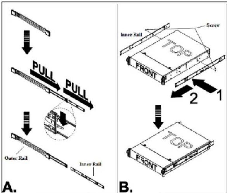
Appendix Device Installation
flowchart
graph TD
    A["Outer Rail"] --> B["PULL"]
    B --> C["Inner Rail"]
    D["Inner Rail"] --> E["PULL"]
    E --> F["Screw"]
    G["Top"] --> H["2"]
    H --> I["1"]
    I --> J["TOP FRONT"]
    style A fill:#f9f,stroke:#333
    style B fill:#f9f,stroke:#333
    style C fill:#f9f,stroke:#333
    style D fill:#f9f,stroke:#333
    style E fill:#f9f,stroke:#333
    style F fill:#f9f,stroke:#333
    style G fill:#f9f,stroke:#333
    style H fill:#f9f,stroke:#333
    style I fill:#f9f,stroke:#333
    style J fill:#f9f,stroke:#333


- Notes
- Contents
- Installation .... 1
- Default System Configuration .... 2
- Web Client Configuration....3
- Q&A....8
- Appendix Device Installation....9
- Installation
- Interfaces and Indicators
- Rear Panel Instruction
- HDD Installation
- Default System Configuration
- Web Client Configuration
- Login
- Disk RAID
- Network Configuration
- Server Port Configuration
- Change Password
- Basic Information
- Date & Time
- Upgrade
- Device Reboot & Shutdown
- Restore Factory Settings
- HTTPS Configuration
- Debug Mode
- Operation Log
- Q&A
- Appendix Device Installation
Brand : Speco Technologies
Model : SB16S
Category : Storage Server