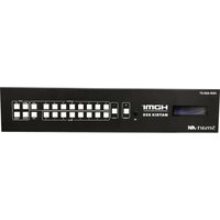
HDR-8×8-XT - Switch Smart-AVI - Free user manual and instructions
Find the device manual for free HDR-8×8-XT Smart-AVI in PDF.


| Product Type | 8x8 HDMI Matrix Switch |
| Brand | Smart-AVI |
| Model | HDR-8×8-XT |
| Video Inputs | 8 x HDMI Type A |
| Video Outputs | 8 x HDMI Type A |
| Max Resolution | 4K@60Hz (3840x2160) |
| HDMI Version | HDMI 2.0 |
| HDCP Support | HDCP 2.2 |
| Control Interfaces | IR, RS-232, Ethernet (TCP/IP) |
| Power Supply | 100-240V AC, 50/60Hz, 30W |
| Dimensions (WxDxH) | 17.0 x 6.0 x 1.75 in (432 x 152 x 44 mm) |
| Weight | 3.0 kg (6.6 lbs) |
| Operating Temperature | 32°F to 104°F (0°C to 40°C) |
| Storage Temperature | -4°F to 140°F (-20°C to 60°C) |
| Humidity | 10% to 90% RH (non-condensing) |
| Audio Support | LPCM, Dolby Digital, DTS up to 7.1ch |
| Rack Mountable | Yes, 1U height with included brackets |
| Maintenance | Clean with a soft dry cloth; avoid liquids |
| Safety | Use only with grounded outlets; do not expose to moisture |
| Spare Parts / Repairability | Contact Smart-AVI for power supply and remote replacements |
| Warranty | 3 years limited warranty |
Frequently Asked Questions - HDR-8×8-XT Smart-AVI
User questions about HDR-8×8-XT Smart-AVI
0 question about this device. Answer the ones you know or ask your own.
Ask a new question about this device
Download the instructions for your Switch in PDF format for free! Find your manual HDR-8×8-XT - Smart-AVI and take your electronic device back in hand. On this page are published all the documents necessary for the use of your device. HDR-8×8-XT by Smart-AVI.
USER MANUAL HDR-8×8-XT Smart-AVI
Distribute 8 4K HDMI sources to 8 local HDMI monitors and 8 remote HDMI displays (16 Total) via HDBaseT with IR, and TCP/IP control support
Smart-AM
SMART AUDIO VIDEO INNOVATION
| TABLE OF CONTENTS | |
| WHAT'S IN THE BOX? 2 | |
| INTRODUCTION 3 | |
| FEATURES 3 | |
| APPLICATIONS 3 | |
| TECHNICAL SPECIFICATIONS 4 | |
| HARDWARE INSTALLATION 5 | |
| FRONT PANEL FUNCTIONS 6 | |
| REAR PANEL 7 | |
| REMOTE CONTROL 8 | |
| CONTROL VIA ETHERNET 9-10 | |
| EDID 11 | |
| HDBaseT RECEIVER 12 | |
| IR CONTROL SYSTEM 13 | |
| LIMITED WARRANTY STATEMENT 14 | |
WHAT'S IN THE BOX?
| PART NO. | QTY | DESCRIPTION |
| HDR-8x8-XTS | 1 | 4K-Ready 8x8 HDMI Matrix Switch with CAT5/6/7 HDBaseT |
| CCPWR06 | 1 | 6' Power Plug Cable |
| RM-HDR8X8XT | 1 | IR Remote Control |
| BRK-HDR8X8XT | 2 | Rack mount brackets |
| 1 | Quick Start Guide |
* Plug in IR emitters and IR eyes for bi-directional remote control of connected devices are sold separately.

Figure 2-1

Figure 2-2
INTRODUCTION
The HDR-8x8-XT with simultaneous CAT5e/6/7 and HDMI outputs connects eight HDMI input sources to sixteen displays. This matrix features eight mirrored HDMI outputs, providing 8 HDMI output ports and 8 CAT-Cable output ports simultaneously. The HDR-8x8-XT supports the transmission of video (resolutions up to 1080p Full HD and 4Kx2K@30Hz) and supports high resolution digital audio formats such as LPCM 7.1CH, Dolby TrueHD, Dolby Digital Plus and DTS-HD Master Audio. Connect an HDBaseT Receiver (Sold Separately) to each of the CAT-Cable outputs to extend the HDMI signal up to 328ft/100m for multi-room connectivity. The HDR-8x8-XT works with Blu-Ray players, Set-Top boxes, Home Theater PCs, and game consoles that connect to an HDMI display. Any source is accessible at all times by any display through the supplied IR Remote Control, TCP/IP, or by using the selection buttons on the front panel. This device supports High Definition Audio, and 3D signal compatibility.
FEATURES
- HDMI input supports: HDMI2.0, HDCP 2.2 and DVI1.0 compliant
• Supports HDMI 3D pass-through - Supports resolutions from VGA\~WUXGA and HD resolutions from 480i\~1080p\~4Kx2K@30 depending on the EDID settings
• Supports transmission distances up to 328ft/100m through CAT5e/6/7 cable
• Supports Power Over Ethernet (POE) function
• Supports simultaneous HDMI and CAT5e/6/7 outputs - Supports wideband IR(30-60Khz) matrix system, IR transport (Plug in IR emitters and IR eyes are sold separately)
- Channels can be forward or backward. And supports GLOBAL IR input and output. (Plug in IR emitters and IR eyes are sold separately)
• Supports remote control, front panel buttons control and TCP/IP Control
• Supports smart EDID management
• Supports Digital Audio and stereo audio outputs - Support bi-directional IR control (Plug in IR emitters and IR eyes are sold separately)
• Supports HDBaseT LAN Serving function
• Supports LPCM 7.1CH, Dolby TrueHD, Dolby Digital Plus and DTS-HD
• Master Audio transmission
APPLICATIONS
- Sports Arenas
- Concert Halls
• Cinemas & Multiplex Theaters - Convention Centers
- Hotel Lobbies
- Transportation Hubs (Airports, Train Stations)
TECHNICAL SPECIFICATIONS
| VIDEO | |
| HDMI Format HDMI 1.4, H | HDMI2.0, HDCP 2.2 and DVI1.0 compliant |
| Video Bandwidth 297MHz[10.2Gbps] | |
| Input Resolution Up to 4K | (3840x2160 @ 30Hz) |
| Output Resolution Up to 4K | (3840x2160 @ 30Hz) |
| HDMI Connector Type A 19 pin female | |
| RJ-45 Connector WE/SS 8P8C | |
| AUDIO | |
| Audio Connectors (8) 3.5mm, (8) Coaxial | |
| HDMI Audio Embedded | |
| Supported Audio Formats | LPCM 7.1CH, Dolby TrueHD, Dolby Digital Plus and DTS-HD Master Audio |
| IR | |
| Supported | Wideband IR(30-60Khz) matrix system.IR transport channel can be forward or backward.GLOBAL IR input / output. |
| CONTROL | |
| Front Panel Front panel buttons | |
| IR | Infrared Remote Control 3.5mm connector: (TX and RX) IR Receiver/IR Blaster |
| TCP/IP Control via Ethernet-connected computer | |
| OTHER | |
| Input Ports | (8) HDMI, (10) IR Receiver, (1) RJ-45(PC Control), (8) RS-232 (Phoenix Jack), (1) RJ45 (Ethernet to provide internet access) |
| Output Ports (8) CAT5e/6/7, (9) IR Blaster, (8) HDMI (8) Coax Audio, (8) Digital audio | |
| RS-232 (8) 3-pin Phoenix Jack for bi-directional control with HDBT Receivers | |
| Power Supply | Internal 100-240 VAC 50/60Hz |
| Dimensions 17" W x 14.6" D x 4" H | |
| Weight | 14.9 lbs. Unit only |
| Approvals | UL, CE, ROHS Compliant |
| Operating Temp. 32 to +104°F (0 to 40°C) | |
| Storage Temp. | -4 to +140°F (-20 to 60°C) |
| Humidity | Up to 90% RH (non-condensing |
HARDWARE INSTALLATION
BASIC SETUP:
- Turn the power off on the HDR-8X8-XT. Do not hotplug! Insert and extract cables carefully with the power switch off. Connecting and disconnecting while the HDR-8X8-XT is powered can result in damage to circuitry.
- Connect up to 8 sources to the HDMI inputs on the HDR-8X8-XT.
- Connect up to 8 HDMI displays to the HDMI output ports on the HDR-8X8-XT.
- Connect up to 8 HDBaseT receivers (Sold Separately) with HDMI displays connected to them to the HDBaseT output ports on the HDR-8X8-XT.
- Optionally connect up to 8 stereo speaker pairs or stereo amplifiers to the audio output ports on the HDR-8X8-XT.
- Optionally connect the HDR-8X8-XT RJ45 PC CONTROL port to your network for remote control via the built in Webpage.
- Optionally connect the HDR-8X8-XT RJ45 port labeled ETHERNET to supply internet access to devices connected via HDBaseT receivers.
- For power, plug in the HDMI sources first, followed by the HDR-8X8-XT Matrix followed by the display receivers, followed by all remaining connected devices.

flowchart
graph TD
    A["HDR-8X8-XT"] -->|HDMI IN| B["Smart AI"]
    A -->|HDMI OUT| B
    A -->|CAT 5e/6| B
    A -->|AUDIO| B
    B --> C["328 Feet with HDBaseT"]
    C --> D["HDPEL PRO"]
    C --> E["HDPEL PRO"]
    C --> F["HDPEL PRO"]
    C --> G["HDPEL PRO"]
    C --> H["HDPEL PRO"]
    C --> I["HDPEL PRO"]
    C --> J["HDPEL PRO"]
    C --> K["HDPEL PRO"]
    C --> L["HDPEL PRO"]
    C --> M["HDPEL PRO"]
    C --> N["HDPEL PRO"]
    C --> O["HDPEL PRO"]
    C --> P["HDPEL PRO"]
    C --> Q["HDPEL PRO"]
    C --> R["HDPEL PRO"]
    C --> S["HDPEL PRO"]
    C --> T["HDPEL PRO"]
    C --> U["HDPEL PRO"]
    C --> V["HDPEL PRO"]
    C --> W["HDPEL PRO"]
    C --> X["HDPEL PRO"]
    C --> Y["HDPEL PRO"]
    C --> Z["HDPEL PRO"]
    C --> AA["HDPEL PRO"]
    C --> AB["HDPEL PRO"]
    C --> AC["HDPEL PRO"]
    C --> AD["HDPEL PRO"]
    C --> AE["HDPEL PRO"]
    C --> AF["HDPEL PRO"]
    C --> AG["HDPEL PRO"]
    C --> AH["HDPEL PRO"]
    C --> AI["HDPEL PRO"]
    C --> AJ["HDPEL PRO"]
    C --> AK["HDPEL PRO"]
    C --> AL["HDPEL PRO"]
    C --> AM["HDPEL PRO"]
    C --> AN["HDPEL PRO"]
    C --> AO["HDPEL PRO"]
    C --> AP["HDPEL PRO"]
    C --> AQ["HDPEL PRO"]
    C --> AR["HDPEL PRO"]
    C --> AS["HDPEL PRO"]
    C --> AT["HDPEL PRO"]
    C --> AU["HDPEL PRO"]
    C --> AV["HDPEL PRO"]
    C --> AW["HDPEL PRO"]
    C --> AX["HDPEL PRO"]
    C --> AY["HDPEL PRO"]
    C --> AZ["HDPEL PRO"]
    C --> BA["HDPEL PRO"]
    C --> BB["HDPEL PRO"]
    C --> BC["HDPEL PRO"]
    C --> BD["HDPEL PRO"]
    C --> BE["HDPEL PRO"]
    C --> BF["HDPEL PRO"]
    C --> BG["HDPEL PRO"]
    C --> BH["HDPEL PRO"]
    C --> BI["HDPEL PRO"]
    C --> BJ["HDPEL PRO"]
    C --> BK["HDPEL PRO"]
    C --> BL["HDPEL PRO"]
    C --> BM["HDPEL PRO"]
    C --> BN["HDPEL PRO"]
    C --> BO["HDPEL PRO"]
    C --> BP["HDPEL PRO"]
    C --> BQ["HDPEL PRO"]
    C --> BR["HDPEL PRO"]
    C --> BS["HDPEL PRO"]
    C --> BT["HDPEL PRO"]
    C --> BU["HDPEL PRO"]
    C --> BV["HDPEL PRO"]
    C --> BW["HDPEL PRO"]
Figure 5-1

Figure 5-2
FRONT PANEL FUNCTIONS

Figure 6-1
- LCD: Displays all information regarding individual input settings/output settings and EDID management.
- IR: IR Receiver window (accepts only the HDR 8x8 -XT remote control signal).
POWER: Press this button to power the device on/off. The LED will illuminate green when the power is on, red when it is in 'Standby' mode.
LOCK: Press this button to lock all the buttons on the panel, press again to unlock.
3. OUTPUT/INPUT:
To assign an output to an input using the front panel buttons, press the desired output button followed corresponding input.
Examples:
[All] Button, Press OUTPUT ALL, then INPUT 1 and OUTPUTs A/B/C/D/E/F/G/H will be set to INPUT 1.
[PTP] Button, Press PTP, then OUTPUTs A/B/C/D/E/F/G/H will "point to point" map to INPUTs 1/2/3/4/5/6/7/8.
- EDID: The LCD will display the EDID operation.
To configure Smart EDID Operation, press the MENU button to enter the EDID management window. Press the UP or DOWN button to select the needed EDID setting. Press the ENTER button to select the input source to download. Any of the EDID input source listed on the LCD can be downloaded.
REAR PANEL

Figure 7-1
- GND: Connect the Housing to ground.
2. IR Matrix
IR EXT: If the panel sensor is obstructed or the unit is installed in a closed area out of infrared line of sight, an IR RX receiver (EYE) can be inserted into the IR EXT port at the rear to extend the IR sensor range and enable local control of the matrix. (Plug in IR emitters and IR eyes are sold separately) See the IR CONTROL SYSTEM section of this manual for IR INPUT and IR OUTPUT set up and operation.
3. PC CONTROL
TCP/IP: This port is the link for TCP/IP control, connect to an active Ethernet link with an RJ45 terminated cable.
-
AUDIO OUTPUT & RS-232: The coaxial and analog audio outputs allow the audio coming into the HDR-8X8-XT via the HDMI INPUT to be output to stereo speakers or audio amplifiers. The TX and RX for RS232 communication allows you to transmit RS-232 via the corresponding HDBaseT OUTPUT over CAT 5e/6 cables to an HDX-POE-PRO HDBT receiver. For example, you can connect a control PC to the OUTPUT A, RS-232 connector on the HDR-8X8-XT. Then connect an RS-232 device to the RS-232 connector on the HDX-POE-PRO HDBT receiver connected to OUTPUT A on the HDR-8X8-XT.
-
HDMI INPUT: Connect to the HDMI input source devices such as a Computer, DVD player or a Set-top Box with HDMI cables.
-
VIDEO OUTPUT: The HDMI OUTPUT connect to HDMI equipped TVs or monitors and the HDBaseT OUTPUT connects to an HDBaseT Receiver such as the HDX-POE-RX. Each of these outputs works with the corresponding audio and RS-232 outputs in section 4.
-
Ethernet: This slot provides Internet connectivity to the devices connected to the 8 RJ45 OUTPUT ports.
-
AC POWER INPUT: Connect to AC power with AC power cable.
REMOTE CONTROL
- Power on /Standby: Press this button to power on the matrix or put it in standby mode.
- Input port selection area: Press these buttons to select input 1-8. Press the forward/backward buttons to cycle from input 1-8.
- Output port selection area: Press these buttons to select output A-H, including ALL.
First select the Output, then select the Input.
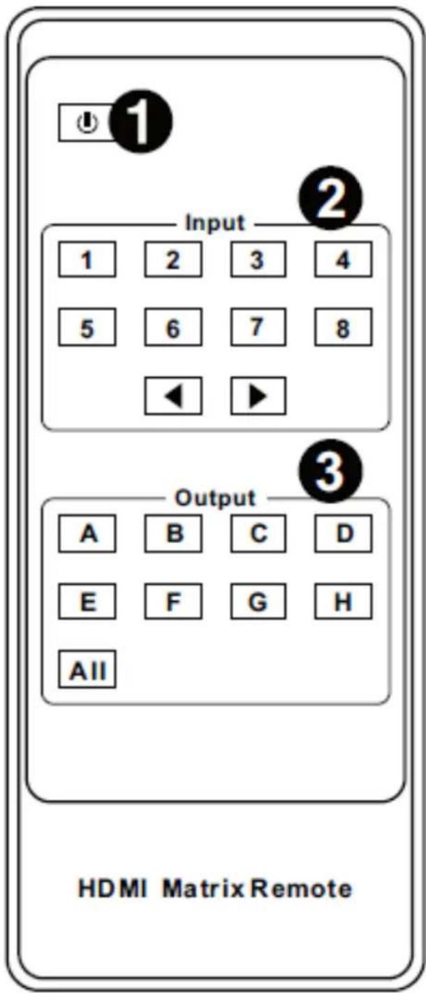
Figure 8-1
CONTROL VIA ETHERNET
HDR-8X8-XT TCP/IP control is a feature that allows source / display switching, EDID configuration and Network settings to be controlled remotely via HTTP. Manage your HDR-8X8-XT with ease from anywhere in the world.
Make sure the HDR-8X8-XT RJ45 PC Control port is connected to your network.
First you must find the IP address. Download the HDR-8X8-XT IP-Finder2 software from http://smartavi.com/helpful-links.html
Once you have unzipped it onto your PC, execute the software and you should see a window like the one shown in Figure 9-1.
Click the [Search Device] button. The IP address for the HDR-8X8-XT should appear.
Enter the IP address into a web browser of your choice. You should see the HDR-8X8-XT Matrix Control Page as shown in Figure 9-2.
Figure 9-1
![USR-TC9232-M4.E15 V2.3.0.78 Device(D) ODIA(L) Help Search List [Click a device to read parameters in the Search List] Device:IP Device Name MAC Version 192.168.1.57 USR K3 D0 00 4CCO 20 23 3010 Baudrate: 115200 (?) PathWDataStop: NONE 8 1 (?) FlowControl: None (?) Work Mode: TCP Server (?) RemotePort: 102.168.0.1 (?) Remote Port: 23 (?) Local Port: 23 (?) TCP Server site: Transparent transmi? (?) ModbusTCP: None (?) PackTime: 10 ms (0-255) (?) PackLeft: 200 DWR (0-1460) (?) Synchronize baudrate:RFC2217 (?) Enable USR Cloud (?) Device ID: 123456789012345678 Communication Code: 12345678 Save COM1 Open Device Device Restart Factory Reset Base Save IP Type: Static IP (?) ModuleStaticIP: 192.168.0.7 (?) SubnetMask: 255.255.255.0 (?) Gateway: 192.168.0.1 (?) Full Show + Base Save On-line Device NUMA1 Search Portb1001](/content/2026/05/1083967/images/ec529d85c42501fffd0aa9a170371a742c89dfc960011792cfa07cd9d6b306cc.jpg)
Figure 9-2

CONTROL VIA ETHERNET (Continued)
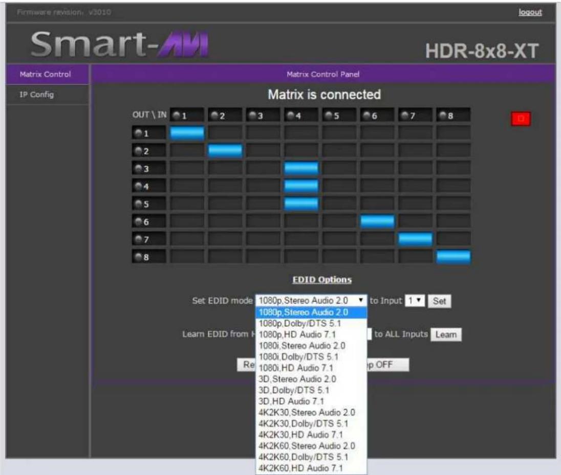
The Matrix Control Page is where you switch inputs to outputs. The column running top to bottom on the left shows the 8 outputs. The Top row shows the inputs or sources. Clicking the box where the input intersects the output sets the connection.
Figure 10-1 shows input or source 1 connected to outputs 1,2,3 &4. Output 5 is connected to Input 5, 6 to 6, 7 to 7 and 8 to 8.
You can also change EDID settings from the Matrix Control Page. See the EDID section of this manual for more information on EDID.
Figure 10-1

The IP Config page shown in Figure 10-2 allows you to modify the network settings.
Figure 10-2

EDID
EDID. What is it and what is it used for?
Under normal circumstances, a source device (digital and analog) will require information about a connected device/display to assess what resolutions and features it can produce. Using this information from the display, the source can then cater its output to send only resolutions and features that are compatible with the attached device/display. This information is called EDID (Extended Display Information Data). A source device can only accept and read one EDID from a connected device/display. Likewise, the source can only output one resolution for use by a connected device/display.
Why is EDID so important with the HDR 8x8 XT ?
The HDR-8x8-XT is a complex piece of technology that replicates and switches between multiple inputs and outputs. Each connected source device will require one EDID to read. EDID management is carefully handled by the HDR-8x8-XT to provide a single EDID for each source to read.
What options do I have to manage the EDID in the HDR 8x8 XT ?
Each source device can only output one video/audio signal type (including resolutions and timings). When multiple devices/displays are used, such as with the HDR-8x8-XT, using devices/displays that have compatible resolutions/features will reduce EDID errors. This will ensure that the single video/audio signal produced by the source device is accepted by all of the connected output devices/displays. The user has the option, through the EDID management window, to choose how the unit will manage the EDID from multiple HDMI devices/displays. The HDR-8x8-XT has multiple EDID management modes that will control how the EDID information from multiple devices/displays are combined, ignored, and routed.
EDID settings can be changed using the front panel buttons and display or from the HDR-8x8-XT control web-page over a network connection.
Figure 11-1
HDBaseT RECEIVER
POWER OVER ETHERNET (POE):
This system can run with only the HDR-8X8-XT powered, RXs do not need to be powered. They are powered via the CAT 5e/6 cable.
INTERNET ACCESS for your connected devices:
The RJ45 connector on the HDBaseT receiver labeled “HDBaseT IN” is for connecting to the HDR-8X8-XT. The RJ45 connector on the HDBaseT receiver labeled “ETHERNET” is for connecting your devices and giving them internet access. The HDR-8X8-XT must have its ETHERNET connector connected to a network with internet access for your connected devices to have internet access.
SETTING UP RS-232 CONTROL with an HDBaseT Receiver: See Figure 12-1
- Connect a control PC to the HDR-8X8-XT with RS-232 cable up to 25 feet long.
- Connect an HDBaseT receiver to the HDR-8X8-XT with CAT 5e/6 cable up to 328 feet long.
- Connect the HDBaseT receiver to the RS-232 capable device with RS-232 cable up to 25 feet long.
- Power on sources first. Then power on the HDR-8X8-XT. Now power on all remaining, connected devices.

flowchart
graph LR
    A["Smart-AVI 3Xi Video Wall Controller With RS-232 Control"] -->|RS-232 Cable up to 25 feet| B["HDBaseT Receiver"]
    B --> C["RS-232 Remote Control PC"]
    C -->|RS-232 Cable up to 25 feet| D["CAT Se/6 Cable up to 328 feet (100 Meters)"]
    D --> E["RS-232 Cable up to 25 feet"]
    style A fill:#f9f,stroke:#333
    style B fill:#ccf,stroke:#333
    style C fill:#cfc,stroke:#333
    style D fill:#fcc,stroke:#333
    style E fill:#cff,stroke:#333
Figure 12-1
HDMI OUT: HDMI output port. This is where you connect the HDMI Display with HDMI cable.
OUTPUT LED: The output status indicating lamp. This red LED illuminates when the Display is connected to the HDMI OUT port.
LINK LED: Connection status indicating lamp.
※Illuminated: The Transmitter and Receiver are connected.
※Flashing: The Transmitter and Receiver have a poor connection.
※Dark: The Transmitter and Receiver are not connected.
DATA LED: Data status indicating lamp.
※Illuminate: HDMI signal with HDCP.
※Flashing: HDMI signal without HDCP.
Dark: No HDMI signal. Figure 12-2

IR CONTROL SYSTEM

IR IN/OUT: Super IR control system interface. (IR Call-back of Matrix and Source Devices)
The matrix is not only a switcher and extender of multiple HDMI signals to multiple remote HDMI receivers. The HDR 8x8 XT also passes IR control signals through the IR call-back system to the matrix and HDMI sources for full, independent control of all connected inputs from output locations.
This matrix has Two-Way IR Call-back between matrix, sources and displays from multiple locations.
A key feature on the matrix is the discrete IR control of the matrix, sources, and displays from any location – inputs at the matrix end can be controlled at a display location and displays can be controlled at the matrix location. Bi-directional IR control across extended set-ups is accomplished by connecting IR emitters/receivers to the matrix, source devices, and SmartAVI receivers (HDX-POE or HDX-POE-PRO). IR signals can then travel both ways via a single CAT5e/6/7 cable.
Plug in IR emitters and IR eyes are sold separately
At Matrix end: Insert the 3.5mm jacks of the IR TX Emitters with the unit into the IR TX Emitter ports at the rear of the matrix according to input. The IR signal is added to the HDMI signal of the input device. For example, if the user is watching Blu-ray on input 1, the IR signal will be directed through the IR TX1 socket to control the device.
Each IR TX port is allocated to an individual HDMI input port. If the user is unable to establish IR control of the device, first check that the IR emitter and HDMI input ports match (Input 1-TX1, Input2-TX2 etc.) with plugs secured in correct ports. Then check that the IR TX emitter sensors are firmly attached directly to the front of inputs and covering infrared sensor windows of the source devices. Some later adjustment may be needed to the location of the sensor to achieve the best performance results - sometimes moving the sensor to different areas on the source can improve IR performance.
NOTE: Infrared receiving areas of devices can be located by shining a flashlight onto the front of the device – the sensor should be able to be seen through the plastic as a small, round object inside. Insert 3.5mm jacks of IR RX receivers into RX ports, making sure the receivers themselves are placed in clear view to receive an infrared signal from the remote handset used to control the display outputs.
At display end: Insert the IR RX Receiver jack into the IR RX port of the display receiver balun, with the receivers themselves placed in clear view on or near the displays to receive an infrared signal from the remote handset used to control inputs. Insert the IR TX Emitter jack into the IR TX port of the display receiver balun, ensuring that the emitter sensor is securely attached to infrared sensor window of the display. Follow the same connection and positioning for all baluns/displays connected to the matrix. If all IR TX Emitters and IR RX Receivers are positioned and connected correctly with sources, displays and display receivers fully powered and the matrix set to IR call-back enabled and IR TX Switch mode activated, two-way IR will now be possible.
Note: Misplaced or poorly secured IR Emitters and Receivers may result in intermittent IR control signals passed to and from the matrix. Check your placement and adjust if necessary.

Figure 13-2
LIMITED WARRANTY STATEMENT
A. Extent of limited warranty
Smart-AVI Technologies, Inc. warrants to the end-user customers that the Smart-AVI product specified above will be free from defects in materials and workmanship for the duration of 1 year, which duration begins on the date of purchase by the customer. Customer is responsible for maintaining proof of date of purchase.
Smart-AVI limited warranty covers only those defects which arise as a result of normal use of the product, and do not apply to any:
a. Improper or inadequate maintenance or modifications
b. Operations outside product specifications
c. Mechanical abuse and exposure to severe conditions
If Smart-AVI receives, during applicable warranty period, a notice of defect, Smart-AVI will at its discretion replace or repair defective product. If Smart-AVI is unable to replace or repair defective product covered by the Smart-AVI warranty within reasonable period of time, Smart-AVI shall refund the cost of the product.
Smart-AVI shall have no obligation to repair, replace or refund unit until customer returns defective product to Smart-AVI.
Any replacement product could be new or like new, provided that it has functionality at least equal to that of the product being replaced.
Smart-AVI limited warranty is valid in any country where the covered product is distributed by Smart-AVI.
B. Limitations of warranty
To the extant allowed by local law, neither Smart-AVI nor its third party suppliers make any other warranty or condition of any kind whether expressed or implied with respect to the Smart-AVI product, and specifically disclaim implied warranties or conditions of merchantability, satisfactory quality, and fitness for a particular purpose.
C. Limitations of liability
To the extent allowed by local law the remedies provided in this warranty statement are the customers sole and exclusive remedies.
To the extant allowed by local law, except for the obligations specifically set forth in this warranty statement, in no event will Smart-AVI or its third party suppliers be liable for direct, indirect, special, incidental, or consequential damages whether based on contract, tort or any other legal theory and whether advised of the possibility of such damages.
D. Local law
To the extent that this warranty statement is inconsistent with local law, this warranty statement shall be considered modified to be consistent with such law.
Smart-AM
SMART AUDIO VIDEO INNOVATION
NOTICE
The information contained in this document is subject to change without notice. SmartAVI makes no warranty of any kind with regard to this material, including but not limited to, implied warranties of merchantability and fitness for particular purpose. SmartAVI will not be liable for errors contained herein or for incidental or consequential damages in connection with the furnishing, performance or use of this material. No part of this document may be photocopied, reproduced, or translated into another language without prior written consent from SmartAVI Technologies, Inc.
20170525
800.AVI.2131
Tel: (818) 503-6200 Fax: (818) 503-6208
11651 Vanowen St. North Hollywood, CA 91605
SmartAVI.com
- INTRODUCTION
- FEATURES
- APPLICATIONS
- HARDWARE INSTALLATION
- BASIC SETUP:
- FRONT PANEL FUNCTIONS
- OUTPUT/INPUT:
- REAR PANEL
- IR Matrix
- PC CONTROL
- REMOTE CONTROL
- CONTROL VIA ETHERNET
- CONTROL VIA ETHERNET (Continued)
- EDID
- EDID. What is it and what is it used for?
- Why is EDID so important with the HDR 8x8 XT ?
- What options do I have to manage the EDID in the HDR 8x8 XT ?
- HDBaseT RECEIVER
- POWER OVER ETHERNET (POE):
- INTERNET ACCESS for your connected devices:
- SETTING UP RS-232 CONTROL with an HDBaseT Receiver: See Figure 12-1
- IR CONTROL SYSTEM
- Plug in IR emitters and IR eyes are sold separately
- LIMITED WARRANTY STATEMENT
- Extent of limited warranty
- Limitations of warranty
- Limitations of liability
- Local law
- Smart-AM
- SMART AUDIO VIDEO INNOVATION
- NOTICE
Brand : Smart-AVI
Model : HDR-8×8-XT
Category : Switch