CSP-142 - In-wall speaker Senal - Free user manual and instructions
Find the device manual for free CSP-142 Senal in PDF.


| Product Type | Condenser Microphone |
| Polar Pattern | Cardioid |
| Frequency Response | 20 Hz - 20 kHz |
| Impedance | 150 ohms |
| Connector | XLR 3-pin |
| Power Requirement | 48V Phantom Power |
| Sensitivity | -35 dB re 1V/Pa |
| Dimensions | 160 x 50 mm (with mount) |
| Weight | 350 g |
| Finish | Black matte |
| Accessories Included | Shock mount, windscreen, carrying case |
| Primary Use | Recording, studio, live vocals |
| Signal-to-Noise Ratio | 78 dB |
| Maximum SPL | 130 dB |
| Maintenance | Wipe with dry cloth; avoid moisture |
| Safety | Use with approved phantom power only |
| Spare Parts and Repairability | Contact Senal for service |
| General Information | Designed for professional audio recording |
Frequently Asked Questions - CSP-142 Senal
User questions about CSP-142 Senal
0 question about this device. Answer the ones you know or ask your own.
Ask a new question about this device
Download the instructions for your In-wall speaker in PDF format for free! Find your manual CSP-142 - Senal and take your electronic device back in hand. On this page are published all the documents necessary for the use of your device. CSP-142 by Senal.
USER MANUAL CSP-142 Senal
natural_image
Four views of a white speaker chamber with visible sound waves and ventilation grilles (no text or symbols)
CSP-SERIES
Thank you for choosing Senal.
The CSP-series speakers are passive coaxial two-way speakers that provide premium sound quality for use with 70V or 100V systems and for low-ohm systems.
These high power - low distortion speakers feature wide coverage that evenly distributes high fidelity audio to fill large and small spaces. All models are ideal for broadcasting announcements and music reproduction in commercial and residential applications.
The CSP-series ceiling speakers have a multi-tap transformer, which allows flexibility in configuring multiple speakers of a high-impedance system. It is easily accessed with the multi-tap selector on the front baffle of the speaker. Low frequencies are enhanced with a vented port, and precise and smooth high frequencies are delivered by the coaxially mounted 3/4" titanium-coated tweeter. The sealed backcan enhances overall fidelity by focusing the sound and preventing the distribution of sound into the surrounding ceiling structure.
Removable locking connectors simplify the process of wiring the speakers. Each speaker comes with the mounting brackets and hardware necessary for installation. The attachment screw system makes installation simple while providing a secure mounting connection to most ceiling types. Secondary support tabs ensure extra security for compliance with building codes. The speakers can be painted to match ceiling décor.
CSP-162
The CSP-162 is a powerful 150-watt, low-distortion ceiling speaker with a built-in multi-tap transformer with maximum power of 60W. It features a 6.5-inch woofer and 3/4" titanium-coated tweeter.
CSP-142
The CSP 142 is a compact 80-watt ceiling speaker with a built-in multi-tap transformer with a maximum power of 30W. It features a 4-inch woofer and 3/4" titanium-coated tweeter. Low clearance of 6.25" (15.9 cm) makes it possible to install this speaker into smaller ceiling spaces.
Table of Contents:
Introduction. 1
Overview 2
Precautions 2
Setting Up 3
Preparing the ceiling 3
Drop Ceilings 3
Fixed Ceilings 3
Connecting the wiring to the removable locking connector....3
Wiring Schemes 4
Attaching and securing the wiring to the speaker....4
Installing the speaker into the ceiling....5
Adjust the Multi-Tap Selector.....5
Attaching the Grille 5
Painting 5
Preparing....5
Painting the rim....5
Painting the grille....5
Specifications 6
Frequency Response 6
Troubleshooting ....7
Three-Year Limited Warranty......7
Overview
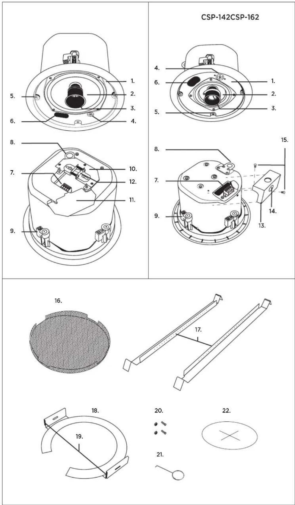
- Front baffle
- Woofer
- Tweeter
- Multi-tap selector
- Attachment screws
- Vented port
- Removable locking connector
- Secondary support tab
- Mounting tabs
- Connector cover plate (CSP-162)
- Cover plate door (CSP-162)
- Adjustable strain-relief fitting (CSP-162)
- Removable cover (CSP-142)
- Knockout (CSP-142)
- (2) Screws (CSP-142)
- Perforated grille
- Rails
- C-Ring
- C-Ring slots
- C-Rings adjuster nuts and bolts
- Grille removal key
- Cutout template
Precautions ⚠️ ⚣️
- Please read and follow these instructions, and keep this manual in a safe place.
- Do not connect the speaker to a high-voltage system when the tap is set on bypass 16 ohms (16R setting on the tap selector). Doing so will damage the speaker.
- Use only the correct, recommended voltage.
- Do not attempt to disassemble or repair this product. Repairs should only be done at an authorized repair shop.
- Keep this product away from water, moisture, and any flammable gases or liquids.
- Handle this product with care.
- Clean this product with a soft dry cloth.
- All photos are for illustrative purposes only.
Setting Up
The CSP-series speakers are designed for easy installation. If necessary, installation can be accomplished without access above the ceiling.
Tools needed for installation
Drywall saw
- Slotted screwdriver
- Phillips head screwdriver
- Wire stripper
- Pencil
Preparing the ceiling
Drop Ceilings
- Locate the ceiling tile in which the speaker is to be mounted and remove the tile from the ceiling.
- Measure to find the center of the tile and place a mark there. Use that mark to center the cutout template on the tile. With a pencil, trace an outline of the cutout template on the tile.
- Use a drywall saw to cut along the traced line.
Pro tip: For easy cleanup it's best to perform this step while placing the tile over an open box or trashcan.

natural_image
Hand holding a pipette over a container with liquid (no text or symbols visible)- Replace the ceiling tile into the ceiling.
- Insert the rails through the hole.
- Place the rails on either side of the hole so that the inverted "V" ends of the rails fit over the ceiling grid rails. The flat side of the rails should rest on the tile, and the side with the pre-cut holes should stand perpendicular on either edge of the hole.
Note: The rails of the mounting bracket do not attach to the ceiling grid rails, but suspend over them.
- Insert the C-ring by angling it through the hole using the open end of the ring.

natural_image
Diagram of a curved mechanical component with an arrow indicating rotation (no text or symbols)Inside-ceiling view of assembled rails and C-ring.
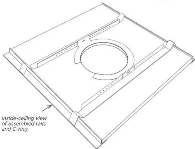
- Fit the slots of the C-ring over the rails and attach it by inserting the bolts through the tabs of the C-ring and securely tightening the nuts.
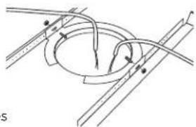
- Pull the speaker wire out so that it extends beyond the ceiling and gives you enough length to complete the installation.
natural_image
Pure technical diagram of a mechanical or electrical component with no visible text, numbers, or symbols.Fixed Ceilings
- Locate the spot where the speaker will be installed
- Use a stud finder to locate studs in the ceiling. Make sure they won't interfere with your installation. If a stud is near the location of your hole, make sure that there is 1-inch clearance between the edge of the hole and the stud.
Pro tip: Drill a small pilot hole and probe inside the ceiling with a stiff wire to make sure there are no obstructions where you are planning on placing the speaker.
- With a pencil, trace an outline of the cutout template on the ceiling.
- Use a drywall saw to cut along the traced line and remove the cutout from the ceiling.
- Pull the speaker wire out so that it extends beyond the ceiling and gives you enough length to complete the installation.
Connecting the wiring to the removable locking connector
CSP-162
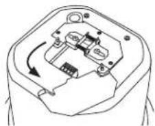
- Open the connector cover plate door.
- Remove the locking connector from the socket
- Strip approximately 1/4" (6 mm) off the ends of the insulation on the speaker wires.
- Insert the exposed ends of the wires into the connector and tighten the screw-down terminals using a small flat blade screwdriver.
natural_image
Pure mechanical component diagram without any text, numbers, or symbols
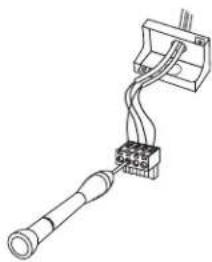
CSP-142
- Remove the cover by unscrewing the two screws attaching it to the backcan.
1.1. Determine the angle your speaker wires approach the speaker and remove the appropriate knockout.
1.2. Feed the wires through the knockout.
- Remove the locking connector from the socket
- Strip approximately 1/4" (6 mm) off the ends of the insulation on the speaker wires.
- Insert the exposed ends of the wires into the connector and tighten the screw-down terminals using a small flat blade screwdriver.

natural_image
Technical line drawing of a connector with a handle and terminal block (no text or symbols)Wiring Schemes
The removable locking connector has four terminals. The pin function of each terminal is listed on the label located on the speaker.
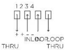
Pins 2 and 3 are the "+" and "-" inputs of the speaker, and they are looped inside the speaker to pins 1 and 4 (Pin 1 connects to Pin 2, and Pin 3 connects to Pin 4.) Pins 1 and 4 are designed as loop-through connections to successive speakers.
Parallel wiring
The advantage of this wiring scheme is that when the connector is pulled out of an individual speaker, the following speakers will remain connected. This wiring scheme is useful when troubleshooting because you can disconnect one speaker at a time from the system without disabling successive speakers. In this scheme pins 1 and 4 have no wires in them.

flowchart
graph TD
    A["FROM AMPLIFIER OR +"] --> B["PREVIOUS SPEAKER"]
    C["1234"] --> D["+ TO NEXT"]
    E[" "] --> F[" Speaker"]
- Insert both "+" wires into pin 2 (one wire from the amplifier or the previous speaker; the other wire to the positive terminal of the next speaker.)
- Insert both “-” wires into pin 3 (one wire from the amplifier or previous speaker; the other wire to the negative terminal of the next speaker.)
- Make sure both screw-down terminals are securely tightened.
Note: Because there are two wires connecting to each terminal, it is important to make sure that the proper contact has been made and that both wires are securely connected with the screw-down terminal.
- Tighten the empty screw-down terminals of pins 1 and 4 to avoid unwanted vibration.
Loop-through wiring
In this scheme, the subsequent speakers are connected via pins 1 "+" & 4 "-" . When one speaker is disconnected, all successive speakers are disconnected too. This scheme can be advantageous when using larger gauge wiring, and when required by local building code. An entire section of speakers can be isolated while not affecting the wiring.

- Insert the "+" and "-" wires from the amplifier or previous speaker into the 2 "+" and 3 "-" pins respectively.
- Insert wires into pin 1 "+" and pin 4 "-" and connect them to the next speaker's pin 2 "+" and pin 3 "-" respectively.
- Make sure all screw-down terminals are securely tightened.

flowchart
graph TD
    A["+"] --> B["AMPLIFIER"]
    B --> C["2 3 4"]
    C --> D["Channel 1"]
    C --> E["Channel 2"]
    C --> F["Channel 3"]
    D --> G["To Subsequent Speakers"]
    E --> G
    F --> G
    G --> H["+"]
    G --> I["-"]
Attaching and securing the wiring to the speaker
CSP-162
- Using a slotted screwdriver, remove the horizontal screw of the strain-relief fitting closest to the cover plate door.
- Loosen the hold-down screws of the sliding pieces of the strain-relief fitting with a Phillips head screwdriver.
- Run the wires through the opening of the fitting and plug the removable locking connector into the connector socket in the speaker.
Warning: DO NOT FORCE THE CONNECTOR INTO THE SOCKET.
- Replace the horizontal screw that was removed.
- Tighten the strain relief fitting by gradually tightening both of the horizontal screws.
- Once the speaker cable is securely clamped into place, tighten the two hold-down screws.
Caution: If using plenum cable, do not over tighten the strain relief fitting. It can strip the cable and cause damage.
- Once the wires have been installed and are securely clamped, close the cover plate door and secure it by tightening the screw with a Phillips head screwdriver.

natural_image
Technical line drawing of an electrical component with wires and connectors (no text or symbols)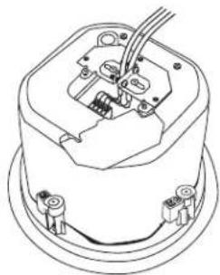
natural_image
Technical line drawing of an electrical component with wires and connectors (no text or symbols)CSP-142
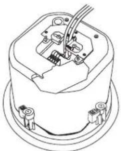
- Plug the removable locking connector with the connected speaker wires into the connector socket in the speaker.
Warning: DO NOT FORCE THE CONNECTOR INTO THE SOCKET.
- Replace the cover by replacing the two screws attaching it to the backcan.
Important: Make sure all wiring conforms to local building codes.
Installing the speaker into the ceiling
Before installing the speaker into the ceiling, it is recommended to attach a safety line to the secondary support tab. Consult local codes for more information about secondary support requirements.

natural_image
Technical line drawing of a mechanical or electrical component with wires and connectors (no text or symbols)- Remove the grille by inserting the included grille removal key in any hole at the edge of the grille and pull out to lift the grille.
- Insert the speaker into the ceiling until the rim is flush with the ceiling. Make sure to tuck any excess wire into the ceiling behind the speaker.
- While supporting the speaker from below, use a Phillips head screwdriver to tighten the mounting tabs by turning the attachment screws CLOCKWISE.
Note: The first quarter rotation turns the mounting tabs outward. Make sure that all the mounting tabs have turned out before tightening all the attachment screws.

natural_image
Simple line drawing of a mechanical tool or device with a screwdriver inserted, no text or symbols present.Caution: DO NOT OVER TIGHTEN. Over tightening can weaken or damage the ceiling tile or ceiling structure and damage the mounting tabs.
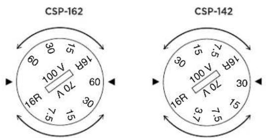
Adjust the Multi-Tap Selector
Before attaching the grille, set the multi-tap selector dial to the appropriate setting. Delay attaching the grilles until the taps for all speakers in the system are adjusted.
The multiple taps of the CSP series allow the flexibility of determining how much power each speaker drives. For low-ohm systems, set the dial to the "16R" position.
Caution: ⚠️ DO NOT CONNECT THE SPEAKER TO A HIGH-VOLTAGE SYSTEM WHEN THE TAP IS SET ON BYPASS 16 OHMS (16R SETTING ON THE TAP SELECTOR). DOING SO WILL DAMAGE THE SPEAKER.
Attaching the Grille
- Place the grille over the speaker baffle.
- Press the edge of the grille into place until it is level with the rim.
Note: Pressing on the center can dent the grille.

Caution: Make sure the grill is firmly seated into the speaker to prevent it from vibrating or falling.
Painting
Preparing
Remove the grille by inserting the included grille removal key in any hole at the edge of the grille and pull out to lift the grille. Clean off any oily residue by rubbing the surfaces with a cloth dampened with a mild solvent (like mineral spirits) and wait until dry. Do not use a wire brush, sandpaper, harsh detergents, chemicals, or strong solvents to prepare these surfaces. It can cause permanent damage to the grille and rim.
Painting the rim
Apply at least two coats of either latex or oil-based paint to the rim. For best results apply a coat of oil-based primer first.
Painting the grille
Spray on at least two thin coats of latex or oil-based paint. Applying the paint to the grille with a brush or roller is not advised because it can create clogs in the mesh and diminish the sound quality of the speaker. After the paint has dried, replace the grille.
Caution: When painting the speaker after it is installed, make sure to cover the speaker baffle. Do not attempt to paint the interior of the speaker. It could cause permanent damage.
Specifications
| CSP-142 CSP-162 | ||
| Height: | 6.25" (15.9 cm) 7.5" (20 cm) | |
| Width: | 7" (17.8 cm) 8.7" (22 cm) | |
| Width w/ rim: | 8.5" (21.6 cm) | 9.7" (24.6 cm) |
| Weight: | 4.95 lb. (2.25 kg) 7.85 lb. (3.56 kg) | |
| Frequency Response: | 80 Hz to 20 kHz 75 Hz to 20 kHz | |
| Power capacity: | 80 Watts 150 Watts | |
| Max SPL: | 85dB SPL, 1W @ 1m 90dB SPL, 1W @ 1m | |
| Transformer Tap: | 70V: 30W, 15W, 7.5W, 3.7W100V: 30W, 15W, 7.5W16 Ohms transformer bypass | 70V: 60W, 30W, 15W, 7.5W100V: 60W, 30W, 15W16 Ohms transformer bypass |
| Low frequency driver: | 4" (10.2 cm) 6.5" (16.5 cm) | |
| High frequency driver: | 3/4" (19 mm) | 3/4" (19 mm) |
| Input connections: | Removable locking connector with screw-down terminals | Removable locking connector with screw-down terminals |
| Speaker Impedance: | 16 Ohms | 16 Ohms |
Frequency Response
CSP-162

line
| Frequency | dBSPL | | --------- | ----- | | 20 Hz | 50 | | 50 | 75 | | 100 | 85 | | 500 | 90 | | 1K | 92 | | 5K | 98 | | 10K | 96 | | 20K | 100 |CSP-142

line
| Frequency | dBSPL | | --------- | ----- | | 20 Hz | 50 | | 50 | 65 | | 100 | 85 | | 500 | 85 | | 1K | 85 | | 5K | 90 | | 10K | 95 | | 20K | 100 |Troubleshooting
| Problem Possible Causes Solution | ||
| No Sound Amplifier | Make sure the amplifier is getting an | input signal.Make sure the volume knob is turned up.Make sure the amp channel output is connected to the correct channel input.Make sure the amplifier is not faulty. Connect the cable to another amplifier. If there is output, the problem was the amplifier. If not, the problem may be the cable. |
| Wiring Make sure the cables are securely connected.Make sure the removable locking connectors are fully inserted into the sockets of the speakers. | ||
| Low speaker volume | Multi-tap selector Change the multi-tap selector to the correct settings. | |
| Amplifier Make sure the amplifier wattage and impedance matches the speakers.Make sure the amplifier volume knob is turned up. | ||
| Wiring Make sure the correct connections have been made, and the screw-down terminals are tightly holding the speaker wire. | ||
| Noise: Crackling or intermittent output | Faulty Amplifier or devices Try operating the system with a different amplifier. | |
| Wiring Check all wires for proper connector contact. | ||
| Noise: buzzing Faulty devices in the signal chain Make sure the noise is not being introduced by a faulty input device. | ||
| Electromagnetic interference Make sure the speaker cable is not running parallel with an electrical cable.Remove light dimmers, fluorescent lamps, or other appliances from the same circuit. | ||
| Noise: humming Ground loop or faulty ground Make sure the system runs a single isolated ground.Make sure the third ground prong on the power cords have not been removed. | ||
| Poor low-frequency output | Polarity shift Make sure that the “+” and “-” wires from the amplifier are not crossed on one or more of the speakers (refer to instructions in Connecting the wiring to the removable locking connector section on page 3). | |
| Vibration of the speaker is causing buzzing in the ceiling | Metal backcan Make sure the metal backcan is not making contact with anything else in the ceiling. | |
| Mounting tabs Make sure the mounting tabs were released from their resting positions and have been sufficiently tightened (refer to instructions in Installing the speaker into the ceiling section on page 5). | ||
| C-ring | Make sure the nuts and bolts of the C-ring slots have been sufficiently tightened (refer to instructions in Installing the speaker into the ceiling section on page 5). | |
| Ceiling tile | Place dampening material under the ceiling grid rail of the drop ceiling or along the edge of the ceiling tile. | |
Three-Year Limited Warranty
This SENAL product is warranted to the original purchaser to be free from defects in materials and workmanship under normal consumer use for a period of three (3) years from the original purchase date or thirty (30) days after replacement, whichever occurs later. The warranty provider's responsibility with respect to this limited warranty shall be limited solely to repair or replacement, at the provider's discretion, of any product that fails during normal use of this product in its intended manner and in its intended environment. Inoperability of the product or part(s) shall be determined by the warranty provider. If the product has been discontinued, the warranty provider reserves the right to replace it with a model of equivalent quality and function.
This warranty does not cover damage or defect caused by misuse, neglect, accident, alteration, abuse, improper installation or maintenance. EXCEPT AS PROVIDED HEREIN, THE WARRANTY PROVIDER MAKES NEITHER ANY EXPRESS WARRANTIES NOR ANY IMPLIED WARRANTIES, INCLUDING BUT NOT LIMITED TO ANY IMPLIED WARRANTY OF MERCHANTABILITY OR FITNESS FOR A PARTICULAR PURPOSE. This warranty provides you with specific legal rights, and you may also have additional rights that vary from state to state.
To obtain warranty coverage, contact the Senal Customer Service Department to obtain a return merchandise authorization ("RMA") number, and return the defective product to Senal along with the RMA number and proof of purchase. Shipment of the defective product is at the purchaser's own risk and expense.
For more information or to arrange service, visit www.senalsound.com or call Customer Service at 212-594-2353.
Product warranty provided by the Gradus Group.
www.gradusgroup.com

SENAL™
A Gradus Group Brand
Senal is a registered trademark of the Gradus Group. © 2014 Gradus Group LLC. All Rights Reserved.
- CSP-SERIES
- Thank you for choosing Senal.
- CSP-162
- CSP-142
- Table of Contents:
- Overview
- Precautions ⚠️ ⚣️
- Setting Up
- Tools needed for installation
- Preparing the ceiling
- Drop Ceilings
- Fixed Ceilings
- Connecting the wiring to the removable locking connector
- Wiring Schemes
- Parallel wiring
- Loop-through wiring
- Attaching and securing the wiring to the speaker
- Installing the speaker into the ceiling
- Adjust the Multi-Tap Selector
- Attaching the Grille
- Painting
- Preparing
- Painting the rim
- Painting the grille
- Frequency Response
- Troubleshooting
- Three-Year Limited Warranty
Brand : Senal
Model : CSP-142
Category : In-wall speaker