
APAX-5080-AE - Input/Output Modules Advantech - Free user manual and instructions
Find the device manual for free APAX-5080-AE Advantech in PDF.


| Product Type | Input/Output Module |
| Series | APAX-5000 Series |
| Model Number | APAX-5080-AE |
| Brand | Advantech |
| Dimensions (W x H x D) | 32 mm x 90 mm x 100 mm |
| Weight | 200 g |
| Power Supply Voltage | 24 VDC |
| Power Consumption | 3 W (typical) |
| Main Functions | Analog and digital I/O, signal conditioning, data acquisition |
| Input Channels | 8 analog input channels, 16 digital input channels |
| Output Channels | 4 analog output channels, 8 digital output channels |
| Communication Interface | Ethernet, Modbus TCP/IP |
| Operating Temperature | -10°C to 60°C |
| Storage Temperature | -20°C to 85°C |
| Humidity Range | 10% to 90% non-condensing |
| Enclosure Rating | IP20 |
| Mounting | DIN rail |
| Maintenance and Cleaning | Use a dry, soft cloth to clean the exterior. Do not use solvents or abrasive cleaners. Ensure power is disconnected before cleaning. |
| Safety Precautions | Follow ESD handling procedures. Do not operate with exposed wiring. Use only specified power supply. |
| Spare Parts and Repairability | No user-serviceable parts. Contact Advantech support for repairs. The module is designed for replacement rather than repair. |
| General Information | Comes with built-in diagnostic LEDs, supports hot-swapping, and includes configuration software. |
Frequently Asked Questions - APAX-5080-AE Advantech
User questions about APAX-5080-AE Advantech
0 question about this device. Answer the ones you know or ask your own.
Ask a new question about this device
Download the instructions for your Input/Output Modules in PDF format for free! Find your manual APAX-5080-AE - Advantech and take your electronic device back in hand. On this page are published all the documents necessary for the use of your device. APAX-5080-AE by Advantech.
USER MANUAL APAX-5080-AE Advantech
APAX-5000 Series
I/O Modules
Copyright
The documentation and the software included with this product are copyrighted 2017 by Advantech Co., Ltd. All rights are reserved. Advantech Co., Ltd. reserves the right to make improvements in the products described in this manual at any time without notice. No part of this manual may be reproduced, copied, translated or transmitted in any form or by any means without the prior written permission of Advantech Co., Ltd. Information provided in this manual is intended to be accurate and reliable. However, Advantech Co., Ltd. assumes no responsibility for its use, nor for any infringements of the rights of third parties, which may result from its use.
Acknowledgements
Intel and Pentium are trademarks of Intel Corporation.
Microsoft Windows and MS-DOS are registered trademarks of Microsoft Corp.
All other product names or trademarks are properties of their respective owners.
Product Warranty (2 years)
Advantech warrants to you, the original purchaser, that each of its products will be free from defects in materials and workmanship for two years from the date of purchase.
This warranty does not apply to any products which have been repaired or altered by persons other than repair personnel authorized by Advantech, or which have been subject to misuse, abuse, accident or improper installation. Advantech assumes no liability under the terms of this warranty as a consequence of such events.
Because of Advantech's high quality-control standards and rigorous testing, most of our customers never need to use our repair service. If an Advantech product is defective, it will be repaired or replaced at no charge during the warranty period. For out-of-warranty repairs, you will be billed according to the cost of replacement materials, service time and freight. Please consult your dealer for more details.
If you think you have a defective product, follow these steps:
-
Collect all the information about the problem encountered. (For example, CPU speed, Advantech products used, other hardware and software used, etc.) Note anything abnormal and list any onscreen messages you get when the problem occurs.
-
Call your dealer and describe the problem. Please have your manual, product, and any helpful information readily available.
-
If your product is diagnosed as defective, obtain an RMA (return merchandize authorization) number from your dealer. This allows us to process your return more quickly.
-
Carefully pack the defective product, a fully-completed Repair and Replacement Order Card and a photocopy proof of purchase date (such as your sales receipt) in a shippable container. A product returned without proof of the purchase date is not eligible for warranty service.
-
Write the RMA number visibly on the outside of the package and ship it prepaid to your dealer.
Part No. 2003H01301 Edition 2
Printed in Taiwan September 2017
Declaration of Conformity
CE
This product has passed the CE test for environmental specifications when shielded cables are used for external wiring. We recommend the use of shielded cables. This kind of cable is available from Advantech. Please contact your local supplier for ordering information.
FCC Class A
Note: This equipment has been tested and found to comply with the limits for a Class A digital device, pursuant to part 15 of the FCC Rules. These limits are designed to provide reasonable protection against harmful interference when the equipment is operated in a commercial environment. This equipment generates, uses, and can radiate radio frequency energy and, if not installed and used in accordance with the instruction manual, may cause harmful interference to radio communications. Operation of this equipment in a residential area is likely to cause harmful interference in which case the user will be required to correct the interference at his own expense.
FM
This equipment has passed the FM certification. According to the National Fire Protection Association, work sites are classified into different classes, divisions and groups, based on hazard considerations. This equipment is compliant with the specifications of Class I, Division 2, Groups A, B, C and D indoor hazards.
Technical Support and Assistance
- Visit the Advantech web site at www.advantech.com/support where you can find the latest information about the product.
- Contact your distributor, sales representative, or Advantech's customer service center for technical support if you need additional assistance. Please have the following information ready before you call:
– Product name and serial number
– Description of your peripheral attachments
– Description of your software (OS, version, application software, etc.)
– A complete description of the problem
– The exact wording of any error messages
Safety Precaution - Static Electricity
Follow these simple precautions to protect yourself from harm and the products from damage.
To avoid electrical shock, always disconnect the power from your PC chassis before you work on it. Don't touch any components on the CPU card or other cards while the PC is on.
Disconnect power before making any configuration changes. The sudden rush of power as you connect a jumper or install a card may damage sensitive electronic components.
Safety Instructions
- Install the system only in area with restricted access.
- Read these safety instructions carefully.
- Keep this User Manual for later reference.
- Disconnect this equipment from any AC outlet before cleaning. Use a damp cloth. Do not use liquid or spray detergents for cleaning.
- For plug-in equipment, the power outlet socket must be located near the equipment and must be easily accessible.
- Keep this equipment away from humidity.
- Put this equipment on a reliable surface during installation. Dropping it or letting it fall may cause damage.
- The openings on the enclosure are for air convection. Protect the equipment from overheating. DO NOT COVER THE OPENINGS.
- Make sure the voltage of the power source is correct before connecting the equipment to the power outlet.
- Position the power cord so that people cannot step on it. Do not place anything over the power cord.
- All cautions and warnings on the equipment should be noted.
- If the equipment is not used for a long time, disconnect it from the power source to avoid damage by transient overvoltage.
- Never pour any liquid into an opening. This may cause fire or electrical shock.
- Never open the equipment. For safety reasons, the equipment should be opened only by qualified service personnel.
- If one of the following situations arises, get the equipment checked by service personnel:
- The power cord or plug is damaged.
- Liquid has penetrated into the equipment.
- The equipment has been exposed to moisture.
- The equipment does not work well, or you cannot get it to work according to the user's manual.
- The equipment has been dropped and damaged.
- The equipment has obvious signs of breakage.
- DO NOT LEAVE THIS EQUIPMENT IN AN ENVIRONMENT WHERE THE STORAGE TEMPERATURE MAY GO BELOW -20° C ( -4° F) OR ABOVE 60° C ( 140° F). THIS COULD DAMAGE THE EQUIPMENT. THE EQUIPMENT SHOULD BE IN A CONTROLLED ENVIRONMENT.
- CAUTION: DANGER OF EXPLOSION IF BATTERY IS INCORRECTLY REPLACED. REPLACE ONLY WITH THE SAME OR EQUIVALENT TYPE RECOMMENDED BY THE MANUFACTURER, DISCARD USED BATTERIES ACCORDING TO THE MANUFACTURER'S INSTRUCTIONS.
- The sound pressure level at the operator's position according to IEC 704-1:1982 is no more than 70 dB (A).
DISCLAIMER: This set of instructions is given according to IEC 704-1. Advantech disclaims all responsibility for the accuracy of any statements contained herein.
Contents
Chapter 1 Overview......1
1.1 Introduction 2
Table 1.1: Supported I/O Module List....2
1.2 I/O Wiring 4
1.3 Removing the I/O Terminal 5
1.4 Labeling the Terminal....6
1.5 Jumper Settings 7
1.6 ID Switch Setting....8
1.7 Mechanical Assembly and Power Connection 10
1.7.1 Wiring Power Input to the Backplane.... 10
1.7.2 Using the APAX-5343E Power Supply Module.... 14
1.8 Decommission and Disposal.... 17
1.9 Mounting 18
1.9.1 DIN-rail Mounting 18
1.9.2 Wall (Panel) Mounting.... 20
Chapter 2 Analog Input/Output Modules .....25
2.1 Analog Input Modules 26
2.1.1 APAX-5013 8-ch RTD Module 26
Figure 2.1 APAX-5013 Module Front View....26
Figure 2.2 Wiring for APAX-5013 27
2.1.2 APAX-5017 12-ch Analog Input Module 28
Figure 2.3 APAX-5017 Module Front View....28
Figure 2.4 Wiring for APAX-5017 28
2.1.3 APAX-5017H 12-ch High Speed Analog Input Module....30
Figure 2.5 APAX-5017H Module Front View 30
Figure 2.6 Wiring for APAX-5017H....31
2.1.4 APAX-5018 12-ch Thermocouple Input Module 32
Figure 2.7 APAX-5018 Module Front View....32
Figure 2.8 Wiring for APAX-5018 33
2.1.5 APAX-5017PE 12-ch Analog Input Module for P&E Applications
36
Figure 2.9 APAX-5017PE Module Front View 36
Figure 2.10 Wiring for APAX-5017PE....36
2.2 Analog Output Modules.... 39
2.2.1 APAX-5028 8-ch Analog Output Module 39
Figure 2.11APAX-5028 Module Frontal View 39
Figure 2.12 Wiring for APAX-5028 40
2.2.2 APAX-5028 Specifications 40
Chapter 3 Digital Input/Output Modules .....41
3.1 Digital Input/Output Modules 42
3.1.1 APAX-5040 24-ch Digital Input Module 42
Figure 3.1 APAX-5040 Module Front View....42
Figure 3.2 Wiring for APAX-5040 42
3.1.2 APAX-5045 24-ch Digital Input/Output Module.... 44
Figure 3.3 APAX-5045 Module Frontal View 44
Figure 3.4 Wiring for APAX-5045 45
3.1.3 APAX-5046 24-ch Digital Output Module....47
Figure 3.5 APAX-5046 Module Front View....47
Figure 3.6 Wiring for APAX-5046 47
3.1.4 APAX-5040PE 24-ch Digital Input Module for P&E Applications 49
Figure 3.7 APAX-5040PE Module Front View.... 49
Figure 3.8 Wiring for APAX-5040PE 50
3.1.5 APAX-5046SO 20-ch Digital Output Module 51
Figure 3.9 APAX-5046SO Module Front View 51
Figure 3.10 Wiring for APAX-5046SO 51
3.2 Relay Output Modules 53
3.2.1 APAX-5060 12-ch Relay Output Module 53
Figure 3.11APAX-5060 Module Frontal View.... 53
Figure 3.12 Wiring for APAX-5060 54
3.2.2 APAX-5060PE 12-ch Relay Output Module for P&E Applications
56
Figure 3.13APAX-5060PE Module Frontal View 56
Figure 3.14 Wiring for APAX-5060PE 56
3.3 Counter Modules....59
3.3.1 APAX-5080 Counter/Frequency and DIO Module 59
Figure 3.15APAX-5080 Module Front View.... 59
Figure 3.16 Wiring for APAX-5080 60
Figure 3.17Pulse/DIR, No Reload, Count Once 64
Figure 3.18Pulse/DIR, With Reload, Count Once 64
Figure 3.19Pulse/DIR, With Reload, Count Repetitively ..... 65
Figure 3.20Up/Down, No Reload, Count Once 66
Figure 3.21Up/Down, With Reload, Count Once.... 67
Figure 3.22Up/Down, With Reload, Count Once....68
Figure 3.23Up, No Reload, Count Once....69
Figure 3.24Up, With Reload, Count Once 69
Figure 3.25Up, With Reload, Count Repetitively 70
Figure 3.26Frequency 70
Figure 3.27A/B Phase 1X, No Reload, Count Once.... 71
Figure 3.28A/B Phase 1X, With Reload, Count Once .... 72
Figure 3.29A/B Phase 1X, With Reload, Count Repetitively ..... 73
Figure 3.30A/B Phase 2X, No Reload, Count Once....74
Figure 3.31A/B Phase 2X, With Reload, Count Once .... 75
Figure 3.32A/B Phase 2X , With Reload , Count Repetitively .... 76
Figure 3.33A/B Phase 4X, No Reload, Count Once....77
Figure 3.34A/B Phase 4X, With Reload, Count Once .... 78
Figure 3.35A/B Phase 4X, With Reload, Count Repetitively ..... 79
Figure 3.36Pulse/DIR, With Reload, Count Once, DI Gate Disable 80
Figure 3.37Pulse/DIR, With Reload, Count Repetitively, DI Gate Disable 81
Figure 3.38Pulse/DIR, With Reload, Count Once, DI Gate Enable, High level, Not Retriggerable .... 82
Figure 3.39Pulse/DIR, With Reload, Count Repetitively, DI Gate Enable, High level, Not Retriggerable 83
Figure 3.40Pulse/DIR, With Reload, Count Repetitively, DI Gate Enable, High level, Not Retriggerable .... 84
Figure 3.41 Pulse/DIR, With Reload, Count Repetitively, DI Gate Enable, High level, Retriggerable....85
Figure 3.42Pulse/DIR, With Reload, Count Repetitively, DI Gate Enable, Low level, Retriggerable....86
Figure 3.43Pulse/DIR, With Reload, Count Repetitively, DI Gate Enable, Low level, Not Retriggerable ....87
Figure 3.44Pulse/DIR, With Reload, Count Once, DI Gate Enable, Low level, Retriggerable....88
Figure 3.45Pulse/DIR, With Reload, Count Repetitively, DI Gate Enable, Low level, Retriggerable....89
Figure 3.46Pulse/DIR, With Reload, Count Once, DI Gate Enable, Rising Edge, Not Retriggerable....90
Figure 3.47Pulse/DIR, With Reload, Count Repetitively, DI Gate
Enable, Rising Edge, Not Retriggerable.... 91
Figure 3.48 Pulse/DIR, With Reload, Count Once, DI Gate Enable, Rising Edge, Retriggerable....92
Figure 3.49Pulse/DIR, With Reload, Count Repetitively, DI Gate Enable, Rising Edge, Retriggerable 93
Figure 3.50Pulse/DIR, With Reload, Count Once, DI Gate Enable, Falling Edge, Not Retriggerable .... 94
Figure 3.51 Pulse/DIR, With Reload, Count Repetitively, DI Gate Enable, Falling Edge, Not Retriggerable 95
Figure 3.52Pulse/DIR, With Reload, Count Once, DI Gate Enable, Falling Edge, Retriggerable .... 96
Figure 3.53Pulse/DIR, With Reload, Count Repetitively, DI Gate Enable, Falling Edge, Retriggerable....97
Figure 3.54Pulse/DIR, With Reload, Count Once, DI Gate Enable, Rising Edge Start....98
Figure 3.55Pulse/DIR, With Reload, Count Repetitively, DI Gate Enable, Rising Edge Start 99
Figure 3.56Pulse/DIR, With Reload, Count Once, DI Gate Enable, Falling Edge Start .... 100
Figure 3.57Pulse/DIR, With Reload, Count Repetitively, DI Gate Enable, Rising Edge Start .... 101
Chapter 4 Interface Module....103
4.1 APAX-5490 4-port RS-232/422/485 Communication Module....104
Figure 4.1 APAX-5490 Module Front View and connection example.... 104
4.2 APAX-5435 APAX iDoor Expansion module....106
4.3 APAX-5090 4-port RS-232/422/485 Communication Module 107
4.4 APAX-5430 SATA Interface Module 109
4.4.1 Specification.... 109
4.4.2 Installation Process.... 109
4.4.3 Setup RAID function in BIOS 110
Chapter 5 Backplane Modules ......117
5.1 APAX-5002/5002L 2-slot Backplane Module 118
5.2 APAX-5001 1-slot Backplane Module 119
Chapter 6 Power Supply Modules ......121
6.1 APAX-5343E Power Supply for Expansion Modules 122
6.2 APAX-5342 48VDC Power Supply for APAX-5580 series 123
6.2.1 Product Specifications 123
6.2.2 Wiring.... 124
6.2.3 Connectors.... 125
Chapter 6 Error Handling and Diagnostics.....127
6.1 Error Handling and Diagnostics 128
Chapter 1
Overview
1.1 Introduction
This manual will discuss the specifications, functions and application wiring of the APAX-5000 series of I/O modules. Advantech provides different APAX-5000 I/O modules for various applications. The following table outlines Advantech's supported I/O modules.
| Table 1.1: Supported I/O Module List | ||
| Module | Name | Specifications |
| Analog I/O APAX | X-5013 8-ch RTD | Module |
| APAX-5017 12-ch | Analog Input Module | |
| APAX-5018 12-ch | Thermocouple Input Module | |
| APAX-5017H 12-ch | High Speed Analog Input Module | |
| APAX-5028 8-ch | Analog Output Module | |
| Digital I/O APAX | -5040 24-ch Digital Input Module | |
| APAX-5045 24-ch Digital Input/Output Module | ||
| APAX-5046 24-ch Digital Output Module | ||
| APAX-5046SO | 20-ch Source Type Digital Output Module | |
| Relay Output APAX | -5060 12-ch Relay Output Module | |
| Counter APAX-5080 Counter/Frequency and DIO module | ||
| Communication | APAX-5490 4-port RS-232/422/485 Communication Module by APAX-5402 | |
| APAX-5090 4-port RS-232/422/485 Communication Module by APAX Bus | ||
| APAX-5435 APAX iDoor Technology Expansion Module | ||
1.2 I/O Wiring
APAX-5000 I/O modules leverage detachable clamp type terminal blocks. Comparing with traditional screw type terminal blocks, clamp type terminal blocks can save up to 75% wiring time and provide better reliability for shock and vibration. Follow the procedures below for wiring your APAX-5000 I/O module.
- Insert the screw driver into the left hole of the terminal.
- Insert the wiring into the right hole of the terminal.
Note! Please use # 14 AWG \~ 28 AWG wire for terminal block.


1.3 Removing the I/O Terminal
APAX-5000 I/O modules provide detachable terminal blocks that are convenient when wiring needs to be changed, because the terminal block can removed and the module doesn't need to be. Refer to the figures below to remove the terminal block.
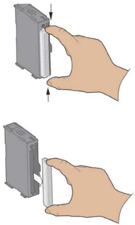
Warning!
APAX-5000 I/O modules can be categorized into four categories: AI, AO, DI and DO. If you insert a terminal block into a module which has a different function, it might damage the modules (for example, inserting a DO terminal block on DI module). In order to prevent this, APAX-5000 modules color the terminal block and label on the front side. Remember to match the terminal block with the module as below.

| Function Color | |
| Analog Input Green | |
| Analog Output Blue | |
| Digital Input Yellow | |
| Digital Output Red |

1.4 Labeling the Terminal
Advantech provides write-on labels for each APAX-5000 I/O module. This write-on label has two sides, one with the model name, specifications and a wiring diagram, while the other side allows users to write information in by themselves. Refer to the figures below for the write-on label details.

1.5 Jumper Settings
Some I/O modules need to be configured manually through the onboard jumpers. This section will show you how to adjust the jumper settings.
- Pull out the write-on label and you can see the location of the jumper.
- You can use the screw driver to adjust the jumper setting.
- Once the jumper setting is done, slide the write-on label back to its position.


1.6 ID Switch Setting
The controller identifies each APAX-5000 I/O module through the ID number. Therefore, you need to set ID number for each I/O module by the rotary ID switch on the front side. Rotate that ID switch and point the hole on the central axis to corresponding ID number ("0" \~ "F"). Refer to figures below for the location of the rotary ID switch and how to set the ID number by the rotary ID switch.
Note!

APAX supports locate functionality. It means the selected APAX I/O module will flash its LED to let you identify through Apax/Adam utility. Refer to related APAX controller or coupler software manual for how to operate it.

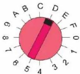
The ID for I/O module is "D"

The ID for I/O module is "4"
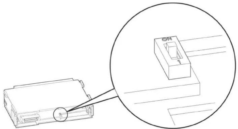
From the figures above, you can choose ID number 0 \~ 15 from the rotary ID switch ("0" \~ "F"). Therefore, the maximum number for analog module in one system is 16. For digital modules, there is another ID switch on the PCB that it can double the available ID number. Thus, the maximum number for digital module in one system is 32.
You can distinguish if the ID number is doubled by the front LED. When the LED color is green, only 0 \~ 15 ID number is used (0 \~ 15 according to the rotary ID switch). Once the LED color is orange, the ID number is doubled (16\~31 according to the rotary ID switch). Refer to figure below for its location and how to configure it.
| DIP Switch Setting ID LED Color | ||
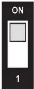 | 16 ~ 31 according to the rotary ID swich | Orange |
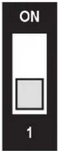 | 0 ~ 15 according to the rotary ID swich | Green |
Warning!
Avoid two modules with the same ID number in the same system, or you cannot see the module in the software utility. The LED on the front side will flash four times if two or more modules have the same ID number in one system. If this happens, simply change the ID number for these conflicted modules and all of them can be found in utility again.

1.7 Mechanical Assembly and Power Connection
1.7.1 Wiring Power Input to the Backplane
There are two ways that APAX-5000 I/O mdoules can be powered. One is to connect the DC power supply wire directly to the power connector on the backplane. Another way is using APAX-5343E power supply module.
When you wire the power supply to the backplane, the power is transferred between backplanes, and provides to all APAX-5000 I/O modules inserted on the backplanes. Refer to figures below for how to wiring the power to the backplane, and how to assembly APAX-5000 I/O modules with backplanes:
- Connect the power supply wire to the power connectors on the 2-slot APAX-5002 backplane module.

Warning! If you use APAX-5000 digital modules in the same system, use different power supplies for the system and the the digital channels on the modules to ensure isolation protection between digital channels and system.
- Insert one APAX-5000 I/O module on that APAX-5002 backplane module.

- Lock that APAX-5000 I/O module to the APAX-5002 backplane by pulling down the module locks.

- Insert another APAX-5000 I/O module on the same APAX-5002 backplane. Use tongue-and-groove slots to move the module.
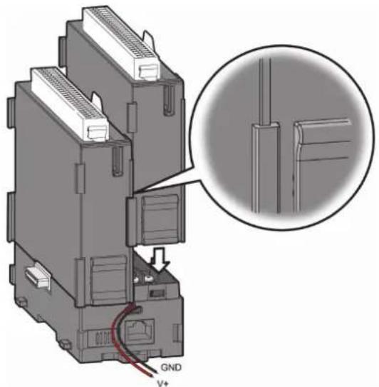
- Lock that APAX-5000 I/O module to the APAX-5002 backplane by pulling down the module locks.

- If you need more than one APAX-5000 I/O module, stack another APAX-5002 backplane to the original APAX-5002 backplane.

Warning!
When you assembly different backplanes together, remember to turn off the power connected to the backplane. If not, the backplanes may be damaged. Turn on the power again after you complete the assembly for all backplanes.

- Lock the stacked APAX-5002 backplane to the original APAX-5002 backplane by the backplane locks.
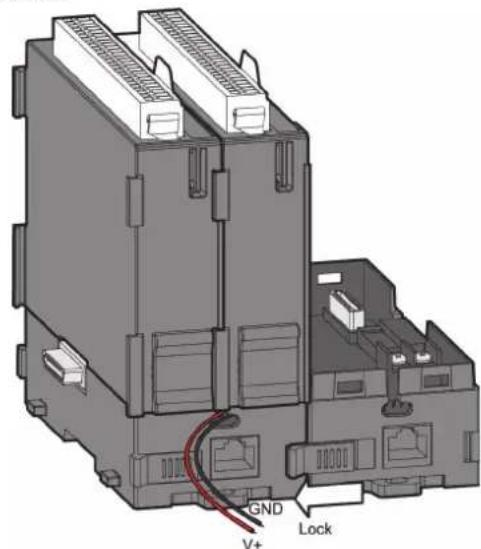
Note!
If you want to provide more power to the system, you can connect another power supply wire to the power connections on the second APAX-5002 backplane. (The wiring procedure is the same as step 1)

- Insert another APAX-5000 I/O module on the second APAX-5002 backplane.

- Lock that APAX-5000 I/O module to the second APAX-5002 backplane by pull down the module locks, similar as step 5.
- If needed, repeat step 8 \~ 9 to have another APAX-5000 I/O module on the same APAX-5002 backplane.
If you need more APAX-5000 I/O module, repeat Step 6 \~ Step 10 until all necessary APAX-5000 I/O modules are inserted on the backplanes.
When the total number of APAX-5520 and APAX-5000 I/O modules is odd, you can use 1-slot APAX-5001 backplane module as the last backplane in the system.

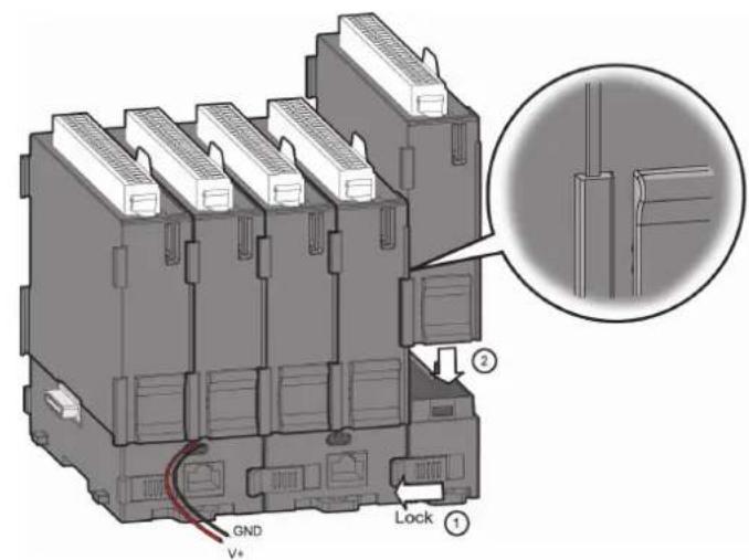

1.7.2 Using the APAX-5343E Power Supply Module
APAX-5000 I/O modules can also be powered by the APAX-5343E power supply module, connected to the left side of the whole system. The power can be transferred to APAX-5000 I/O modules though the backplanes.
Note!Refer to Chapter 5 for APAX-5343E specifications.

-
Follow the procedure described in Section 1.7.1 to assembly APAX-5000 I/O modules into one complete system. The only difference is that you don't need to connect the power supply wiring to the power connectors on the backplane (step 1 in Section 1.7.1).
-
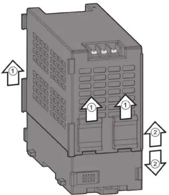
Pull up the module locks on the upper case of one APAX-5343E. Then you can separate the upper case of APAX-5343E from its backplane.

- Stack the backplane of APAX-5343E to the left side of the first APAX-5002 backplane in the system.

- Lock the stacked APAX-5343E backplane with the APAX-5002 backplane by the backplane locks on the APAX-5002 backplane.

- Insert the upper case of APAX-5343E back to its backplane. Use tongue-and-groove slots to move the upper case.

- Lock the upper case of APAX-5343E to its backplane by pulling down the module locks on the upper case. Connect AC power code to the power connectors on the upper case of APAX-5343E. Then the whole system is powered-on.

1.8 Decommission and Disposal
APAX-5000 I/O modules support hot-swap functionality. It means the I/O module can be removed from the backplane or inserted on the backplane when the complete system is power-on. This can significantly help to make it more convenient for system maintenance. Changing one module won't affect operation of other modules. The hot-swap functionality is implemented by the module locks. Refer to figure below for how to dismantle APAX-5000 I/O modules:
- Pull up the two module locks on side of APAX-5000 I/O modules first. This action disconnects the power between the I/O module and backplane.
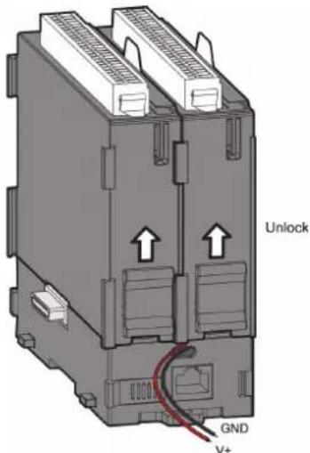
Note!If you only want to remove one module, the procedure is similar. (Pull up the module locks and then remove the module without shutting down the power)
- Detach APAX-5000 I/O module from the backplane.

Repeat Step 1 \~ Step 2 for all the APAX-5000 I/O modules you want to remove.
It is the similar when you insert APAX-5000 I/O modules back to the backplane. First, insert APAX-5000 I/O module to backplane. Then, pull down the two module locks to lock on the backplane, and APAX-5000 I/O module will be power-on and can be used.
The device must be fully dismantled in order to dispose of it. Electronic parts must be disposed of in accordance with national electronics scrap regulations.
1.9 Mounting
1.9.1 DIN-rail Mounting
APAX-5000 I/O module can be mounted through backplane to the following DIN rails: 35 x 7.5 mm or 35 x 15 mm. Below are the procedures for the DIN rails mounting.
- Pull down the DIN rail lock at the back of APAX-5002 backplane.
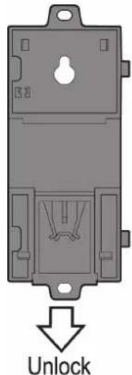
- Attach the APAX-5002 backplane on the DIN rail.

- Repeat Step 1 \~ Step 2 until necessary APAX-5002 backplanes are all attached on the DIN rail.
Note!
When the total number of APAX-5520 and APAX-5000 I/O modules is odd, you can use APAX-5001 (1-slot backplane) as the last backplane in the system. And the procedure to attach APAX-5001 on the DIN rail is similar as APAX-5002.

-
Move all backplanes to stack them together. Then slide the backplane locks on the backplanes to fasten all backplanes. (Similar to Step 6 and 7 in section 1.7.1)
-
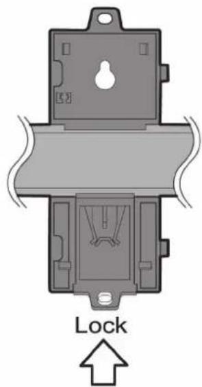
Slide the DIN rail lock of all backplanes into the position, to fix all backplanes to the DIN rail.
-
Insert all necessary APAX-5000 I/O modules to the backplanes. (Similar to Step 2, Step 4 and Step 8 in section 1.7.1)
-
Slide the module lock of those APAX-5000 I/O modules into the position, to fix these modules to related backplanes. (Similar to Step 3, Step 5 and Step 9 in section 1.7.1)
1.9.2 Wall (Panel) Mounting
Mount the APAX-5000 I/O module to a wall (panel) through backplane using two screws per module. Use M4 or #8 panhead screws. Refer to figure below for the dimensional template:

Below are the procedures for the wall (panel) mounting:
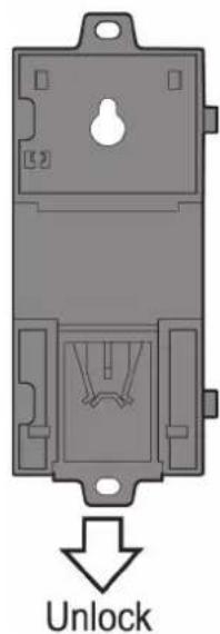
- Pull down the DIN-rail lock at the back of the first APAX-5002 backplane.
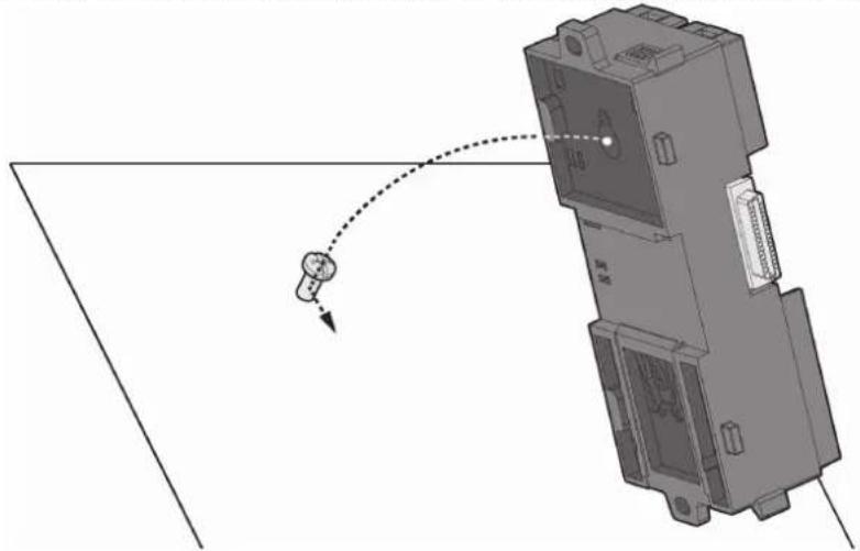
- Hang the APAX-5002 backplane onto the screw on the wall (panel). The screw for APAX-5002 to hang should be special-designed. We have provided it in accessory. (Diameter: 9 mm, length: 16 mm, height of head: 2.7 mm)
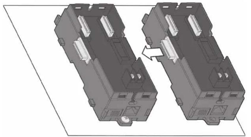
- Mount the first APAX-5002 backplane to the wall (panel) using two standard M4 or #8 panhead screws. We also provide the two screws in accessory. (Diameter: 7 mm, length: 8 mm, height of head: 2.6 mm)

- Stack Another APAX-5002 backplane to original backplane. Lock the two backplanes together.
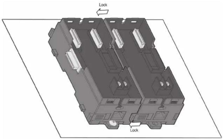
- Mount the second APAX-5002 backplane to the wall (panel) using two standard M4 or #8 panhead screws.
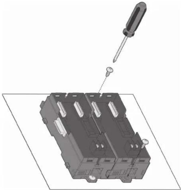
- Repeat Step 4 \~ Step 5 until all necessary APAX-5002 backplane are screwed on the wall (panel).
Note!
When the total number of APAX-5000 I/O modules is odd, you can use APAX-5001 (1-slot backplane) as the last backplane in the system. The procedure to attach APAX-5001 on the wall is similar as APAX-5002.


- Insert all necessary APAX-5000 I/O modules to the backplanes. (Similar to Step 2, Step 4 and Step 8 in section 1.7.1)
- Lock APAX-5520 and all necessary APAX-5000 I/O module to the backplane by pull down the buckle. (Similar to Step 3, Step 5 and Step 9 in section 1.7.1)
Warning! In order to have better ventilation remember to align the APAX-5000 I/O modules as follows:

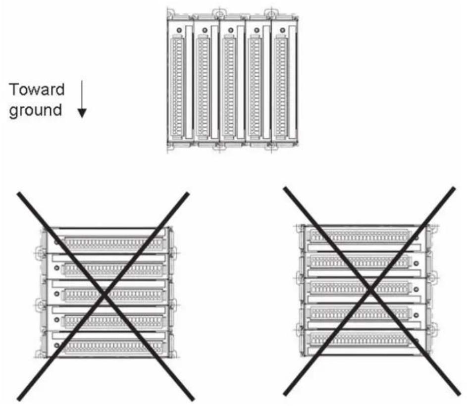
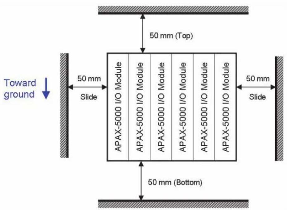
We suggest remaining enough clearance space from enclosure walls and adjacent equipments. Allow 50 mm (2 in.) of space on all sides, as shown below. This provide ventilation and makes assembly more easily.
Chapter 2
Analog Input/Output Modules
2.1 Analog Input Modules
Analog input modules use an A/D converter to convert sensor voltage, current, thermocouple or RTD signals into digital data. The analog input modules protect your equipment from ground loops and power surges by providing opto-isolation of the A/D input and transformer based isolation up to 2,500 VDC.
2.1.1 APAX-5013 8-ch RTD Module
The APAX-5013 is a 16-bit, 8-channel RTD input module that features programmable input ranges on all channels. This module is an extremely cost-effective solution for industrial measurement and monitoring applications. Its opto-isolated inputs provide 2,500 VDC of isolation between the analog input and the module, protecting the module and peripherals from damage due to high input line voltage.
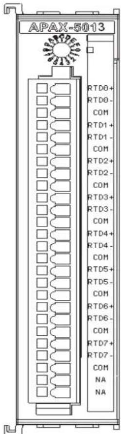
Figure 2.1 APAX-5013 Module Front View
Application Wiring

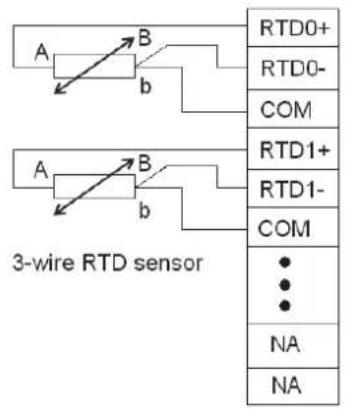
Figure 2.2 Wiring for APAX-5013
APAX-5013 Technical Specifications
Channels: 8
■ Input Impedance: >10 MΩ
■ Input Type: Pt-100, Pt-200, Pt-500, Pt-1000, Balco, Ni 518 RTD (2-wire and 3-wire)
Temperature Range: Pt-100, Pt-200, Pt-500, Pt-1000: -120\~130°C, -200\~850°C
– Supports IEC 60751 ITS90 (0.03851Ω/Ω/°C) and JIS C 1604 (0.03916 Ω/Ω/°C)
– Balco 500: -30 \~ 120°C
– Ni 518: -80 \~ 100°C, 0 \~ 100°C
■ Configure Different Range for Each Channel: Yes
■ Resolution: 16-bit
Accuracy: ±0.1 % of FSR (at 25°C)
Sampling Rate: 50 Hz filter: 8 sample/second (total) 60 Hz filter: 10 sample/second (total)
CMR @ 50/60 Hz: 90 dBs
■ NMR @ 50/60 Hz: 60 dBs
■ Noise Suppression for Frequency: 50/60 Hz
■ Span Drift: 15 ppm/°C
■ Input Characteristic Curve: According to IEC 61131-2
■ Wire Burnout Detection: All RTD type
Protection
Isolation: 2,500 VDC (Between channels and backplane)
Environment
Operating Temperature: -10 \~ 60° C (when mounted vertically)
■ Storage Temperature: -40 \~ 70°C
■ Relative Humidity: 5 \~ 95% (non-condensing)
General
■ Dimensions (W x H x D): 30 x 139 x 100 mm
Weight: 170 g
■ Power Consumption: 2.5 W @ 24 VDC (typical)
2.1.2 APAX-5017 12-ch Analog Input Module
The APAX-5017 is a 16-bit, 12-channel analog differential input module that provides programmable input ranges on all channels, and different channels can be configured using different ranges. It accepts voltage and current inputs. Adjust the switch (refer to Section 1.5) to define each channel as voltage or current input. Refer to the figure below to see how to define the input type by the jumper. Besides, you can use software (APAX utility) to configure range type for each channel. This module is an extremely cost-effective solution for industrial measurement and monitoring applications. The module provides 2500 VDC optical isolation between channels and backplane bus. If any high voltage or current damage the channels, the whole system (backplanes, other modules, and control unit) won't be affected because it is already isolated.
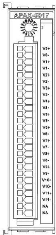
Figure 2.3 APAX-5017 Module Front View

Figure 2.4 Wiring for APAX-5017
Note! To keep measurement accuracy please short the channels that

are not in use.
Note! You can use the jumpers to configure each analog input channel type (voltage or current). Refer to Section 1.5 for the location of the jumpers. There are a total of 12 jumpers and each is specific for one channel.
Technical Specifications of APAX-5017
■ Channels: 12 (Differential)
■ Input Impedance: >10 MΩ (Voltage), 120Ω (Current)
■ Input Type: V, mV, mA
Voltage/Current Range: ±150mV, ±500mV, ±1V, ±5V, ±10V, ±20mA, 0\~20mA, 4\~20 mA
Configure Different Range for Each Channel: Yes
Accuracy: ±0.1% or better (Voltage), ±0.2% or better (Current) at 25°C
Resolution:
| Voltage | |
| Range Resolution | |
| ±150 mV 16 bit | |
| ±500 mV 16 bit | |
| ±1 V 16 bit | |
| ±5 V 16 bit | |
| ±10 V 16 bit | |
| Current | |
| Range Resolution | |
| ±20 mA | 15 bit |
| 0 ~ 20 mA | 14 bit |
| 4 ~ 20 mA | 14 bit |
Note! Please base on 16 bit to convert your raw data to engineer unit in the current mode.

■ Sampling Rate: 12 samples/second (total)
CMR @ 50/60 Hz: 90 dB
NMR @ 50/60 Hz: 67 dB
■ Noise Suppression for Frequency: 50/60 Hz
■ Span Drift: ±30 ppm/°C
■ Zero Drift: ±6 μV/°C
■ Input Characteristic Curve: According to IEC 61131-2
■ Common Mode Voltage: up to 200 VDC
■ Wire Burnout Detection: Only for 4 \~ 20 mA range
Protection
Isolation: 2,500 VDC (Between channels and backplane bus)
■ Over Voltage Protection: ±35 VDC
Operating Temperature: -10 \~ 60°C (when mounted vertically)
■ Storage Temperature: -40 \~ 70°C
■ Relative Humidity: 5 \~ 95% (non-condensing)
Environment
General
■ Dimensions (W x H x D): 30 x 139 x 100 mm
Weight: 170 g
■ Power Consumption: 4 W @ 24 VDC (typical)
2.1.3 APAX-5017H 12-ch High Speed Analog Input Module
APAX-5017H is an 12-ch analog differential input module that provides programmable input ranges on each channel. Its sampling rate depends on the data format received: up to 1000 sample/second (per channel). The module provides 2500 VDC optical isolation between channels and backplane bus. If any high voltage or current damage the channels, the whole system (backplanes, other modules, and control unit) won't be affected because it is already isolated.
Note! There is no built-in filter on APAX-5017H, so please try to use it in an environment with less noise.


Figure 2.5 APAX-5017H Module Front View
Application Wiring

Figure 2.6 Wiring for APAX-5017H
Note! You can use the jumpers to configure each analog input channel type (voltage or current). Refer to Section 1.5 for the location of the jumpers. There are a total of 12 jumpers and each is specific for one channel.
APAX-5017H Specifications
Channels: 12
■ Input Impedance: 2MΩ (Voltage), 120 Ω (Current)
■ Input Type: V, mV, mA
■ Input Range: 0 \~ 500 mV, ±10 V, 0 \~ 10 V, 0 \~ 20 mA, 4 \~ 20 mA
■ Configure Different Range for Each Channel: Yes
Accuracy: ±0.1% or better (voltage), ±0.2% or better (current) at 25°C
■ Resolution: 12-bit
■ Sampling Rate: 1,000 sample/second (per channel)
■ Span Drift: ±25 ppm/°C
■ Zero Drift: ±6 μV/°C
■ Input Characteristic Curve: According to IEC 61131-2
■ Wire Burnout Detection: Only for 4 \~ 20 mA range
Protection
■ Over Voltage Protection: ±35 VDC
Isolation: 2,500 VDC (Between channels and backplane bus)
Note! The voltage between any two pins must not exceed 15 V

Environment
Operating Temperature: -10 \~ 60°C (when mounted vertically)
■ Storage Temperature: -40 \~ 70°C
■ Relative Humidity: 5 \~ 95% (non-condensing)
General
■ Dimensions (W x H x D): 30 x 139 x 100 mm
Weight: 175 g
■ Power Consumption: 3.5 W @ 24 VDC (typical)
Warning! There is no built-in filter on APAX-5017H module, so it is not very suitable to use it in a very noisy environment.

2.1.4 APAX-5018 12-ch Thermocouple Input Module
The APAX-5018 is a 16-bit, 12-channel thermocouple input module that features programmable input ranges on all channels. It accepts millivolt inputs ( ±50\ mV , ±100\ mV , ±500\ mV ), voltage inputs ( ±1\ V , ±2.5\ V ), current input ( ±20\ mA , 020mA , 420mA ) and thermocouple input (Type J, K, T, R, S, E, B). An external CJC on the plug-in terminal is designed for accurate temperature measurement. The module provides 2500 VDC optical isolation between channels and backplane bus. If any high voltage or current damage the channels, the whole system (backplanes, other modules, and control unit) won't be affected because it is already isolated.
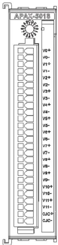
Figure 2.7 APAX-5018 Module Front View
Application Wiring

Figure 2.8 Wiring for APAX-5018
Note! You can use the jumpers to configure each analog input channel type

(voltage/thermocouple or current). Refer to Section 1.5 for the location of the jumpers. There are a total of 12 jumpers and each is specific for one channel.
APAX-5018 Specifications
■ Channels: 12 (Differential)
■ Input Type: V, mV, mA, Thermocouple
■ Voltage/Current Range:
±50mV, ±100mV, ±500mV, ±1V, ±2.5V, ±20mA, 0\~20mA, 4\~20 mA
■ Voltage and Current Accuracy: ±0.1% or better (Voltage), ±0.2% or better (Current) at 25°C
■ Temperature Range and Accuracy:
| Type Range Accuracy | ||
| Type J -210 ~ - | 150 °C ±2.5 °C | |
| -150 ~ 1200 °C ±2 °C | ||
| Type K -230 ~ + | 150 °C ±4 °C | |
| -150 ~ 1372 °C ±2.5°C | ||
| Type T -230 ~ - | 150 °C ±2°C | |
| -150 ~ 400 °C ±1.5°C | ||
| Type E -230 ~ + | 150 °C ±2.5°C | |
| -150 ~ 1000 °C ±2°C | ||
| Type R 0 ~ 100 | °C ±2.5°C | |
| 100 ~ 1768 °C ±2°C | ||
| Type S 0 ~ 100 | °C ±2.5°C | |
| 100 ~ 1768 °C ±2°C | ||
| Type B 200 ~ 40 | 00°C ±4°C | |
| 400 ~ 1820 °C ±3°C | ||
Note! This accuracy information only relates to the operating error, not including cold connection CJC error. The CJC error can be eliminated by performing CJC compensation.
■ Configure Different Range for Each Channel: Yes
Resolution:
| Voltage | |
| Range Resolution | |
| ±50 mV 16 bit | |
| ±100 mV 16 bit | |
| ±250 mV 16 bit | |
| ±500 mV 16 bit | |
| ±1 V 16 bit | |
| ±2.5 V 16 bit | |
| Current | |
| Range Resolution | |
| ±20 mA 15 bit | |
| 0 ~ 20 mA 14 bit | |
| 4 ~ 20 mA 14 bit | |
| Thermocouple | |
| Range Resolution | |
| Type J 14 bit | |
| Type K 14 bit | |
| Type T 15 bit | |
| Type E 15 bit | |
| Type R 14 bit | |
| Type S 14 bit | |
| Type B 14 bit | |
■ Sampling Rate: 12 samples/second (total)
CMR @ 50/60 Hz: 90 dB
NMR @ 50/60 Hz: 67 dB
■ Noise Suppression for Frequency: Hardware Filter (50/60 Hz)
■ Span Drift: ±25 ppm/° C
■ Zero Drift: ±6 μV/°C
■ Thermocouple Wire Burn-out Detection: Yes
(When the loop resistance > 1KΩ, it will detect as wire burn-out)
■ Input Characteristic Curve: According to IEC 61131-2
■ Common Mode Voltage: up to 200 VDC
■ Wire Burnout Detection: For 4 \~ 20 mA range and all thermocouple type
Protection
Isolation: 2,500 VDC (Between channels and backplane bus)
Environment
Operating Temperature: -10 \~ 60°C (when mounted vertically)
■ Storage Temperature: -40 \~ 70°C
■ Relative Humidity: 5 \~ 95% (non-condensing)
General
■ Dimensions (W x H x D): 30 x 139 x 100 mm
Weight: 170 g
■ Power Consumption: 3.5 W @ 24 VDC (typical)
2.1.5 APAX-5017PE 12-ch Analog Input Module for P&E Applications
The APAX-5017PE is a 16-bit, 12-channel analog differential input module that provides programmable input ranges on all channels, and different channels can be configured using different ranges. It accepts voltage and current inputs. You can use software (APAX utility) to configure range type for each channel. This module is an IEC-61850-3 compliant I/O modules, and suitable for measurement and monitoring for power and energy related application. The highly anti-electromagnetic interference make it more robust and reliable to survive in the hush environment. The module also provides 2500 VDC optical isolation between channels and backplane bus. If any high voltage or current damage the channels, the whole system (backplanes, other modules, and control unit) won't be affected because it is already isolated.
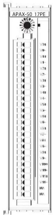
Figure 2.9 APAX-5017PE Module Front View
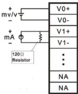
Figure 2.10 Wiring for APAX-5017PE
Note! To keep measurement accuracy please short the channels that

are not in use.
Technical Specifications of APAX-5017PE
■ Channels: 12 (Differential)
■ Input Impedance: >10 MΩ (Voltage)
■ Input Type: V, mV, mA (for current mode, 120Ω resistors is required to be connected in parallel)
Voltage/Current Range: ±150mV, ±500mV, ±1V, ±5V, ±10V, ±20mA, 0\~20mA, 4\~20 mA
■ Configure Different Range for Each Channel: Yes
Accuracy: ±0.1% or better (Voltage), ±0.2% or better (Current) at 25°C
Resolution:
| Voltage | |
| Range Resolution | |
| ±150 mV 16 bit | |
| ±500 mV 16 bit | |
| ±1 V 16 bit | |
| ±5 V 16 bit | |
| ±10 V 16 bit | |
| Current | |
| Range Resolution | |
| ±20 mA | 15 bit |
| 0 ~ 20 mA | 14 bit |
| 4 ~ 20 mA | 14 bit |
■ Sampling Rate: 12 samples/second (total)
CMR @ 50/60 Hz: 90 dB
NMR @ 50/60 Hz: 67 dB
■ Noise Suppression for Frequency: 50/60 Hz
■ Span Drift: ±30 ppm/°C
■ Zero Drift: ±6 μV/°C
■ Input Characteristic Curve: According to IEC 61131-2
■ Common Mode Voltage: up to 200 VDC
■ Wire Burnout Detection: Only for 4 \~ 20 mA range
Protection
Isolation: 2,500 VDC (Between channels and backplane bus)
■ Over Voltage Protection: ±35 VDC
Environment
Operating Temperature: -20 \~ 70°C (when mounted vertically)
■ Storage Temperature: -40 \~ 85°C
■ Relative Humidity: 5 \~ 95% (non-condensing)
General
■ Dimensions (W x H x D): 30 x 139 x 100 mm
Weight: 170 g
■ Power Consumption: 2 W @ 5 VDC (typical)
2.2 Analog Output Modules
2.2.1 APAX-5028 8-ch Analog Output Module
The APAX-5028 is a 8-channel analog output module. It uses the D/A converter controlled by the system module to convert the digital data into output signals. You can specify slew rates and start up currents through the configuration software. For each channel, voltage and current can be used by connecting to different terminal. The module provides 2500 VDC optical isolation between channels and backplane bus. If any high voltage or current damage the channels, the whole system (backplanes, other modules, and control unit) won't be affected because it is already isolated.
Note!
The slew rate is defined as the slope indicated the ascending or descending rate per second of the analog output from the present to the required.


Figure 2.11 APAX-5028 Module Frontal View
Application Wiring
![graph TD A["I0+"] --> B["Device"] C["GND"] --> B D["V0+"] --> B E["I1+"] --> F["Device"] G["GND"] --> F H["V1+"] --> F I["..."] --> F J["NA"] --> K["NA"] L["0"] --> A M["1"] --> C N["..."] --> E O["NA"] --> J](/content/2026/05/1083884/images/831325c0fdb9f6c0bbff8fd71fb3982989eba5003751dbde91060c829cc757a4.jpg)
Figure 2.12 Wiring for APAX-5028
Note! The common terminals are physically connected together and to the backplane power supply ground.

2.2.2 APAX-5028 Specifications
Channels: 8
■ Output Type: V, mA
Output Range: ±2.5 V, ±5 V, ±10 V, 0\~2.5 V, 0\~5 V, 0\~10 V, 0\~20 mA, 4\~20 mA
Configure Different Range for Each Channel: Yes
■ Resolution: 14-bit
Accuracy: ±0.1% of FSR at 25°C
■ Settling Time: About 50 μs to 0.01%
■ Output Latency: 500 μs
■ Slew Rate: 0.7 VDC/μs (per channel)
■ Span Drift: ±60 ppm/°C
■ Zero Drift: ±250 μV/°C
Load: Voltage: 1000 Ω (minimum), Current: 0 \~ 500 Ω
Protection
Isolation: 2,500 VDC (Between channels and backplane bus)
■ Short Circuit Protection
■ Fail Safe Protection*
* When I/O module lose its communication with controller or coupler, the output channel will generate a pre-defined value
Environment
Operating Temperature: -10 \~ 60°C (when mounted vertically)
■ Storage Temperature: -40 \~ 70°C
■ Relative Humidity: 5 \~ 95% (non-condensing)
-
General
■ Dimensions (W x H x D): 30 x 139 x 100 mm
Weight: 175 g
■ Power Consumption: 3.5 W @ 24 VDC (typical)
Chapter 3
Digital Input/Output Modules
3.1 Digital Input/Output Modules
3.1.1 APAX-5040 24-ch Digital Input Module
The APAX-5040 features 24 digital input (sink/source) channels. The APAX-5040 module's digital input channels can accept a 2-wiring input from a DC voltage source, to determine the state of limits, standard switches or proximity switches. The digital input channels offer LED to indicate digital status. The module provides 2500 VDC optical isolation between channels and backplane bus. If any high voltage or current damage the channels, the whole system (backplanes, other modules, and control unit) won't be affected because it is already isolated.
Warning!
Please use different power supply modules for digital channels and system to ensure isolation effect.


Figure 3.1 APAX-5040 Module Front View
Application Wiring
![graph TD A["24Vdc"] --> B["DI 0"] A --> C["DI 1"] A --> D["..."] A --> E["DI 11"] A --> F["COM 0"] A --> G["DI 12"] A --> H["DI 13"] A --> I["..."] A --> J["DI 23"] A --> K["COM 1"] B --> L["or"] C --> L D --> L E --> L F --> L G --> L H --> L I --> L J --> L K --> L](/content/2026/05/1083884/images/03b83ddc866686d16fb16bb89d49db7f5ef60eb02a66a3924a37d988ba54fc32.jpg)
Figure 3.2 Wiring for APAX-5040
APAX-5040 Specifications
Digital Input
Channels: 24
■ Points per Common: 12
■ Type: Sink/Source (Wet Contact)
■ Input Voltage Rated Value: 24 VDC
- For "0" signal: -5 \~ 5 VDC
- For "1" signal: 15 \~ 30 VDC and -15 \~ -30 VDC
■ Input Impedance: 5.4 kΩ
■ Typical Input Current: 4.4 mA (At signal "1")
■ Maximum Input Current: 7.3 mA
■ Input Filter: 3 ms
■ Input Characteristic Curve: According to IEC 61131-2, type 1
Protection
Isolation: 2,500 VDC (Between channels and backplane bus)
■ Over Voltage Protection: ±70 VDC
Environment
Operating Temperature: -10 \~ 60°C (when mounted vertically)
■ Storage Temperature: -40 \~ 70°C
■ Relative Humidity: 5 \~ 95% (non-condensing)
General
■ Dimensions (W x H x D): 30 x 139 x 100 mm
Weight: 160 g
■ Power Consumption: 2 W @ 24 VDC (typical)
■ Status Display: LED per channel
- On: Logic level "1"
- Off: Logic level "0"
3.1.2 APAX-5045 24-ch Digital Input/Output Module
The APAX-5045 features 12 digital input (sink/source) and 12 digital output (sink) channels. The APAX-5045 module's digital input channels can accept a 2-wiring input from a DC voltage source, to determine the state of limits, standard switches or proximity switches. The APAX-5045 module's digital output channels can generate discrete signal to external devices and change its output value to control the devices. The digital output channels offer short-circuit protection and LED to indicate digital status. The module provides 2500 VDC optical isolation between channels and backplane bus. If any high voltage or current damage the channels, the whole system (backplanes, other modules, and control unit) won't be affected because it is already isolated.
Warning! Please use different power supply modules for digital channels and system to ensure isolation effect.


Figure 3.3 APAX-5045 Module Frontal View
Application Wiring
![graph TD A["24Vdc"] --> B["DI 0"] A --> C["DI 1"] A --> D["..."] A --> E["DI 11"] A --> F["COM"] A --> G["DO0"] A --> H["DO1"] A --> I["..."] A --> J["DO11"] A --> K["GND"] B --> L["OR"] C --> L D --> L E --> L F --> M["OR"] G --> M H --> M I --> N["OR"] J --> N K --> N L --> O["24Vdc"]](/content/2026/05/1083884/images/29b5f6170aa5c4df9c260f4be6211f78dc0ddef52d57215e853fd440aba92fde.jpg)
Figure 3.4 Wiring for APAX-5045
Warning!
When you connect DO channel with inductive load, we suggest adding one diode in the circuit to protect the APAX-5045 module. (Refer to figure below)


APAX-5045 Specifications
Digital Input
Channels: 12
■ Points per Common: 12
■ Type: Sink/Source (Wet Contact)
■ Input Voltage Rated Value: 24 VDC
- For "0" signal: -5 \~ 5 VDC
- For "1" signal: 15 \~ 30 VDC and -15 \~ -30 VDC
■ Input Impedance: 5.4 kΩ
■ Input Current: typical 4.4 mA (At signal "1")
■ Input Filter: 3 ms
■ Input Characteristic Curve: According to IEC 61131-2, type 1
Digital Output
Channels: 12
Type: Sink
■ Voltage Range: 8 \~ 35 VDC
Rated Output Current at signal "1": 0.5 A (per channel)
■ Permitted Output Current (at signal "1"): max. 0.75 A
■ Output Current at signal "0" (leakage current): 0.1 mA
Lamp Load: max. 5W
■ On-State Voltage Drop: 0.15 V at 0.5 A
Switch Rate:
- For resistive load: max. 300 Hz
- For inductive load: max. 20 Hz
— For lamp load: max. 200 Hz (Using 5W lamp and tested under 50 Ω, 24 V)
Protection
Isolation: 2,500 VDC (Between channels and backplane bus)
■ Over Voltage Protection: ±70 VDC (for DI channel)
■ Short Circuit Protection (For DO channel)
■ Thermal Shutdown Protection (For DO channel)
- Fail Safe Protection*
* When I/O module lose its communication with controller or coupler, the output channel will generate a pre-defined value
Environment
Operating Temperature: -10 \~ 60° C (when mounted vertically)
■ Storage Temperature: -40 \~ 70°C
■ Relative Humidity: 5 \~ 95% (non-condensing)
General
■ Dimensions (W x H x D): 30 x 139 x 100 mm
Weight: 165 g
■ Power Consumption: 2.5 W @ 24 VDC (typical)
■ Status Display: LED per channel
- On: Logic level "1"
- Off: Logic level "0"
3.1.3 APAX-5046 24-ch Digital Output Module
The APAX-5046 features 24 digital output (sink) channels. The digital output channels offer short-circuit protection and LED to indicate digital status. The module provides 2500 VDC optical isolation between channels and backplane bus. If any high voltage or current damage the channels, the whole system (backplanes, other modules, and control unit) won't be affected because it is already isolated.
Warning! Please use different power supply modules for digital channels and system to ensure isolation effect.


Figure 3.5 APAX-5046 Module Front View
Application Wiring

Figure 3.6 Wiring for APAX-5046
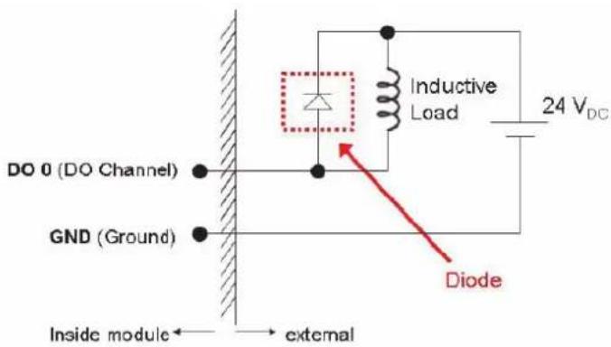
Warning!
When you connect DO channel with inductive load, we suggest adding one diode in the circuit to protect the APAX-5046 module. (Refer to figure below)

APAX-5046 Specifications
Digital Output
Channels: 24
Type: Sink
■ Voltage Range: 8 \~ 35 VDC
Rated Output Current at signal "1": 0.5 A (per channel)
■ Permitted Output Current (at signal "1"): max. 0.75 A
■ Output Current at signal "0" (leakage current): 0.1 mA
Lamp Load: max. 5W
■ On-State Voltage Drop: 0.15 V at 0.5 A
Switch Rate:
- For resistive load: max. 300 Hz
- For inductive load: max. 20 Hz
- For lamp load: max. 200 Hz (Using 5W lamp and testing under 24 V)
Protection
Isolation: 2,500 VDC (Between channels and backplane bus)
■ Short Circuit Protection
■ Thermal Shutdown Protection
■ Fail Safe Protection*
* When I/O module lose its communication with controller or coupler, the output channel will generate a pre-defined value
Environment
Operating Temperature: -10 \~ 60°C (when mounted vertically)
■ Storage Temperature: -40 \~ 70°C
■ Relative Humidity: 5 \~ 95% (non-condensing)
General
■ Dimensions (W x H x D): 30 x 139 x 100 mm
Weight: 165 g
■ Power Consumption: 2.5 W @ 24 VDC (typical)
■ Status Display: LED per channel
- On: Logic level "1"
- Off: Logic level "0"
3.1.4 APAX-5040PE 24-ch Digital Input Module for P&E Applications
The APAX-5040PE features 24 digital input (sink/source) channels. The APAX-5040PE module's digital input channels can accept a 2-wiring input from a DC voltage source, to determine the state of limits, standard switches or proximity switches. The digital input channels offer LED to indicate digital status. This module is an IEC-61850-3 compliant I/O modules, and suitable for power and energy related application. The highly anti-electromagnetic interference make it more robust and reliable to survive in the hush environment. The module provides 2500 VDC optical isolation between channels and backplane bus. If any high voltage or current damage the channels, the whole system (backplanes, other modules, and control unit) won't be affected because it is already isolated.
Warning! Please use different power supply modules for digital channels and system to ensure isolation effect.

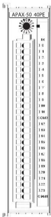
Figure 3.7 APAX-5040PE Module Front View
Application Wiring
![graph TD A["Power Input"] --> B["24Vdc"] B --> C["DI 0"] B --> D["DI 1"] B --> E["..."] B --> F["DI 11"] B --> G["COM 0"] B --> H["DI 12"] B --> I["DI 13"] B --> J["..."] B --> K["DI 23"] B --> L["COM 1"] B --> M["or"]](/content/2026/05/1083884/images/0a0bf570a954bf65ef3272085c63267de89bea402e0344fb08afd6ba906f7cc6.jpg)
Figure 3.8 Wiring for APAX-5040PE
APAX-5040 Specifications
Digital Input
Channels: 24
■ Points per Common: 12
■ Type: Sink/Source (Wet Contact)
■ Input Voltage Rated Value: 24 VDC
- For "0" signal: -5 \~ 5 VDC
- For "1" signal: 15 \~ 30 VDC and -15 \~ -30 VDC
■ Input Impedance: 5.4 kΩ
■ Typical Input Current: 4.4 mA (At signal "1")
■ Maximum Input Current: 7.3 mA
■ Input Filter: 3 ms
■ Input Characteristic Curve: According to IEC 61131-2, type 1
Protection
Isolation: 2,500 VDC (Between channels and backplane bus)
■ Over Voltage Protection: ±70 VDC
Environment
Operating Temperature: -20 \~ 75°C (when mounted vertically)
■ Storage Temperature: -40 \~ 85°C
■ Relative Humidity: 5 \~ 95% (non-condensing)
General
■ Dimensions (W x H x D): 30 x 139 x 100 mm
Weight: 160 g
■ Power Consumption: 2 W @ 24 VDC (typical)
■ Status Display: LED per channel
- On: Logic level "1"
- Off: Logic level "0"
3.1.5 APAX-5046SO 20-ch Digital Output Module
The APAX-5046SO features 20 digital output (source) channels. The digital output channels offer short-circuit protection and LED to indicate digital status. The module provides 2500 VDC optical isolation between channels and backplane bus. If any high voltage or current damage the channels, the whole system (backplanes, other modules, and control unit) won't be affected because it is already isolated.
The APAX-5046SO supports two independent power sources with different voltage levels. For example, one can be 24VDC while the other is 12VDC.
Warning! Please use different power supply modules for digital channels and system to ensure isolation effect.


Figure 3.9 APAX-5046SO Module Front View
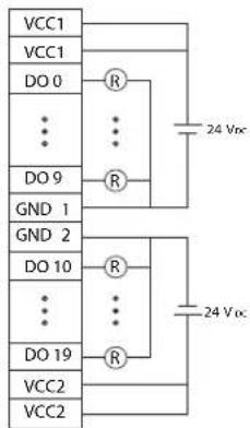
Figure 3.10 Wiring for APAX-5046SO
APAX-5046SO Specifications
Digital Output
Channels: 20
Type: Source
■ Voltage Range: 10 \~ 35 V DC
Rated Output Current at signal "1": 1A (per channel)
■ Permitted Output Current (at signal "1"): max. 1.2A
■ Output Current at signal "0" (leakage current): 0.1 mA
Lamp Load: max. 10 W
■ On-State Voltage Drop: 0.15 V at 0.5 A
Switch Rate:
- For resistive load: max. 300 Hz
- For inductive load: max. 20 Hz
- For lamp load: max. 200 Hz (Using 5W lamp and testing under 24 V)
Protection
Isolation: 2,500 V DC (Between channels and backplane bus)
■ Short Circuit Protection
Thermal Shutdown Protection
Fail Safe Protection*
* When I/O module lose its communication with controller or coupler, the output channel will generate a pre-defined value
Environment
Operating Temperature: -10 \~ 60°C (when mounted vertically)
■ Storage Temperature: -40 \~ 70°C
■ Relative Humidity: 5 \~ 95% (non-condensing)
General
■ Dimensions (W x H x D): 30 x 139 x 100 mm
Weight: 165 g
■ Power Consumption: 2.5 W @ 24 V DC (typical)
■ Status Display: LED per channel
- On: Logic level "1"
- Off: Logic level "0"
3.2 Relay Output Modules
3.2.1 APAX-5060 12-ch Relay Output Module
The APAX-5060 relay output module provides 12 relay channels of Form A. Switches can be used to control the relays. The digital output channels offer short-circuit protection and LED to indicate digital status. The module provides 2500 VDC optical isolation between channels and backplane bus. If any high voltage or current damage the channels, the whole system (backplanes, other modules, and control unit) won't be affected because it is already isolated.

Figure 3.11 APAX-5060 Module Frontal View
Application Wiring

Figure 3.12 Wiring for APAX-5060
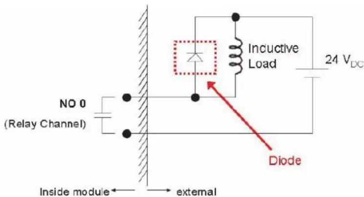
Warning! When you connect DO channel with inductive load, we suggest adding one diode in the circuit to protect the APAX-5060 module. (Refer to figure below)

APAX-5060 Specifications
Relay Output
Channels: 12
■ Relay Type: Form A (SPST)
■ Switching Capacity and Lifetime of the Contact (For Resistive Load)
- VDE: 30,000 operations (5 A @ 250 VAC, 10 operations/minute at 8° C) 70,000 operations (5 A @ 30 VDC, 10 operations/minute at 85° C)
- UL: 60,000 operations (5 A @ 250 VAC)
100,000 operations (5 A @ 30 VDC)
- Mechanism: 20,000,000 operations (no load, 300 operations/minute)
■ Breakdown Voltage: 500 VAC (50/60 Hz)
■ Contact Resistance: 30 mΩ (maximum)
Insulation Resistance: 1 GΩ (minimum) at 500 VDC
■ Operating Time: 10 ms maximum at rated voltage (excluding bounce time)
■ Release Time: 5 ms maximum at rated voltage (excluding bounce time)
Protection
Isolation: 2,500 VDC (Between channels and backplane bus)
■ Fail Safe Protection*
* When I/O module lose its communication with controller or coupler, the output channel will generate a pre-defined value
Environment
Operating Temperature: -10 \~ 60° C (when mounted vertically)
■ Storage Temperature: -40 \~ 70°C
■ Relative Humidity: 5 \~ 95% (non-condensing)
General
■ Dimensions (W x H x D): 30 x 139 x 100 mm
Weight: 195 g
■ Power Consumption: 2 W @ 24 VDC (typical)
■ Status Display: LED per channel
- On: Logic level "1"
- Off: Logic level "0"
3.2.2 APAX-5060PE 12-ch Relay Output Module for P&E Applications
The APAX-5060PE relay output module provides 12 relay channels of Form A. Switches can be used to control the relays. The digital output channels offer short-circuit protection and LED to indicate digital status. This module is an IEC-61850-3 compliant I/O modules, and suitable for power and energy related application. The highly anti-electromagnetic interference make it more robust and reliable to survive in the hush environment. The module provides 2500 VDC optical isolation between channels and backplane bus. If any high voltage or current damage the channels, the whole system (backplanes, other modules, and control unit) won't be affected because it is already isolated.

Figure 3.13 APAX-5060PE Module Frontal View
Application Wiring
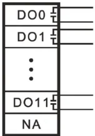
Figure 3.14 Wiring for APAX-5060PE
Warning!
When you connect DO channel with inductive load, we suggest adding one diode in the circuit to protect the APAX-5060PE module. (Refer to figure below)


APAX-5060PE Specifications
Relay Output
Channels: 12
■ Relay Type: Form A (SPST)
■ Switching Capacity and Lifetime of the Contact (For Resistive Load)
- VDE: 30,000 operations (5 A @ 250 VAC, 10 operations/minute at 8° C) 70,000 operations (5 A @ 30 VDC, 10 operations/minute at 85° C)
- UL: 60,000 operations (5 A @ 250 VAC)
100,000 operations (5 A @ 30 VDC)
- Mechanism: 20,000,000 operations (no load, 300 operations/minute)
■ Breakdown Voltage: 500 VAC (50/60 Hz)
■ Contact Resistance: 30 mΩ (maximum)
■ Insulation Resistance: 1 GΩ (minimum) at 500 VDC
■ Operating Time: 10 ms maximum at rated voltage (excluding bounce time)
■ Release Time: 5 ms maximum at rated voltage (excluding bounce time)
Protection
Isolation: 2,500 VDC (Between channels and backplane bus)
- Fail Safe Protection*
* When I/O module lose its communication with controller or coupler, the output channel will generate a pre-defined value
Environment
Operating Temperature: -20 \~ 70°C (when mounted vertically)
■ Storage Temperature: -40 \~ 85°C
■ Relative Humidity: 5 \~ 95% (non-condensing)
General
■ Dimensions (W x H x D): 30 x 139 x 100 mm
Weight: 195 g
■ Power Consumption: 2 W @ 24 VDC (typical)
■ Status Display: LED per channel
- On: Logic level "1"
- Off: Logic level "0"
3.3 Counter Modules
3.3.1 APAX-5080 Counter/Frequency and DIO Module
The APAX-5080 features counter/frequency and DIO functions. For the digital input function, the APAX-5080 supports 4 isolated digital input and Gate function. For digital output function, the APAX-5080 supports 4 general isolated digital output and specific alarm function with counter. For counter/frequency function, the APAX-5080 can support many modes of counter input type such as A/B phase and CW/CCW types. And the frequency input range can support from 0.1Hz to 1MHz. Here is the APAX-5080 module view and application wiring below.

Figure 3.15 APAX-5080 Module Front View
Application Wiring
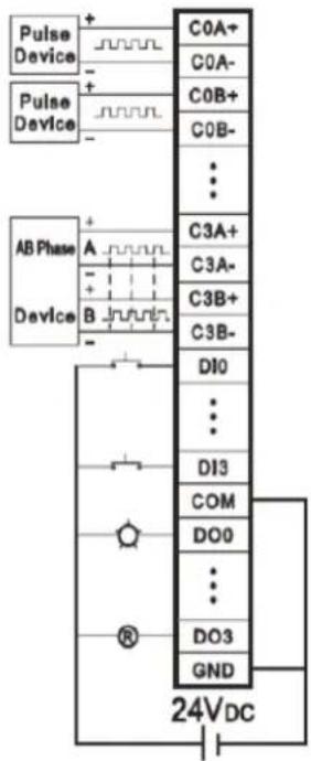
Figure 3.16 Wiring for APAX-5080
Warning! Please use different power supply modules for digital channels and system to ensure isolation effect.

APAX-5080 Function Block
![graph TD A["ALARM OUTPUT"] --> B["ALARM CHANNEL MAP"] B --> C["SINGLE/CONTINUE MODE"] C --> D["OVER/UNDER FLOW"] D --> E["RELOAD MODE"] E --> F["INITIAL VALUE"] F --> G["COUNTER SETTING"] G --> H["GATE CHANNEL MAP"] H --> I["RETRIGGER MODE"] I --> J["HIGH LEVEL"] I --> K["RISING EDGE"] I --> L["LOW…](/content/2026/05/1083884/images/7876a81b1c4430e45749e1c428a9018a1ffec4400e598c7121207f5426496486.jpg)
APAX-5080 Specifications
Digital Input
Channels: 4
Input Voltage
- For "0" Signal: 0 \~ 3 VDC
- For "1" Signal: 10 \~ 30 VDC
■ Input Current: 5\~15 mA (For Signal "1", typical)
■ Minimum Pulse Width: 500 ns (Max. Input Frequency)
Digital Output
Channels: 4
■ Voltage Range: 8 \~ 35 VDC
■ Output Current at Signal "1"
– Rated: 0.5 A
- Permitted: 0.75 A (max.)
■ Output Current at Signal "0"10A
– (Leakage Current)
■ Output Delay at Resistive Load
- From logic level "0" to "1"100 s (max.)
- From logic level "1" to "0"200 s (max.)
Counter Input
■ Modes: Pulse and Direction, Up/Down, Up Pulse, A/B phase and Frequency
■ Channels: 4 (Pulse and Direction, Up/Down, and A/B phase mode)
- 8 (Up Pulse and Frequency mode)
Counting Range: 32-bit + 1-bit overflow/underflow
■ Minimum Pulse Width: 500 ns
■ Input Frequency (max.): 1 MHz
Input Voltage
- For "0" Signal0 \~ 3 VDC
- For "1" Signal10 \~ 30 VDC
■ Input Current: 5\~15 mA (For Signal "1", typical)
Digital Noise Filter: 1\~65000 s (programmable)
Protection
Isolation: 2500 VDC (Between channels and backplane bus)
■ Over Voltage Protection: 50 VDC (all channels)
- 110 VDC (single channel) (for DI and Counter Input channels)
■ Short Circuit Protection: Yes (for DO channels)
Environment
Operating Temperature: -10 \~ 70° C (14 \~ 158° F)
■ Storing Temperature: -25 \~ 85° C (-13 \~ 185° F)
■ Storing Humidity: 5 \~ 95% RH (non-condensing)
General
■ Dimensions (W x H x D): 30 x 139 x 100 mm
Weight: 165 g
■ Power Consumption: 2.5 W @ 24 VDC (typical)
■ Status Display: LED per channel
- On: Logic level "1"
- Off: Logic level "0"
APAX-5080 Counter Mode No Gate No Alarm
There are so many counter modes in APAX-5080 and below will use counter0 as an example to explain every counter mode operation principle.
Below are the definitions of counter mode.
■ Pulse/DIR: Ch0_A provides the counting function, one pulse, one count, and Ch0_B provides the clockwise and counter clockwise function.
Up/Down: CH0_A provides the counter up function, one pulse one up count, and CH0_A provides the counter down function, one pulse one down count.
■ UP: CH0_A provides the counter up function, one pulse one up count.
A/B Phase 1X: counter mode A/B Phase x 1--If the signal "A" leads "B" by a rising or falling edge, then the number of steps will be added by one, and vice versa.
A/B Phase 2X: counter mode A/B Phase x 2
A/B Phase 4X: counter mode A/B Phase x 4
■ With Reload: When the counter0 value is overflow, the value will be reset to the initial value.
No Reload: If the counter0 value is overflow, the value will be 0. If the counter0 value is overflow, the value will be the max value.
Count Once: It means if the counter0 is overflow, it won't count again.
Count Repetitively: when counter value is overflow or underflow, it will reset to the default value and continuous to count.
Frequency: CH0_A provides the frequency function from 0.1Hz\~1MHz.
Pulse/DIR, No Reload, Count Once
Figure 3.3 shows pulse/direction mode, Ch0_A provides the counting function, one pulse, one count. Ch0_B provides the clockwise and counter clockwise function. When the counter0 is enabled, the counter0 starts to count. If the counter value is overflow or underflow, it will show the minimum (0x00) or maximum (0xFFFFFFF) value and not count continuously.


Figure 3.17 Pulse/DIR, No Reload, Count Once
Pulse/DIR, With Reload, Count Once
Figure 3.4 shows pulse/direction mode, Ch0_A provides the counting function, one pulse, one count. Ch0_B provides the clockwise and counter clockwise function. When the counter0 is enabled, the counter0 starts to count. If the counter value is overflow or underflow, it will reset to the defined value (e.g. 0x33) but won't keep counting.
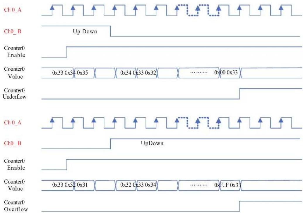
Figure 3.18 Pulse/DIR, With Reload, Count Once
Pulse/DIR, With Reload, Count Repetitively
Figure 3.5 shows pulse/direction mode, Ch0_A provides the counting function, one pulse, one count. Ch0_B provides the clockwise and counter clockwise function. When the counter0 is enabled, the counter0 starts to count. If the counter value is overflow or underflow, it will reset to the defined value (e.g. 0x33) and keep counting repetitively.

Figure 3.19 Pulse/DIR, With Reload, Count Repetitively
Up/Down, No Reload, Count Once
Figure 3.6 shows up/down mode, Ch0_A provides the counting up function, one pulse, one up count. Ch0_B provides the counting down function, one pulse, one down count. When the counter0 is enabled, the counter0 starts to count. If the counter value is overflow or underflow, it will show the minimum (0x00) or maximum (0xFFFFFFF) value and not count continuously.

Figure 3.20 Up/Down, No Reload, Count Once
Up/Down, With Reload, Count Once
Figure 3.7 shows up/down mode, Ch0_A provides the counting up function, one pulse, one up count. Ch0_B provides the counting down function, one pulse, one down count. When the counter0 is enabled, the counter0 starts to count. If the counter value is overflow or underflow, it will reset to the defined value (e.g. 0x33) but won't keep counting.
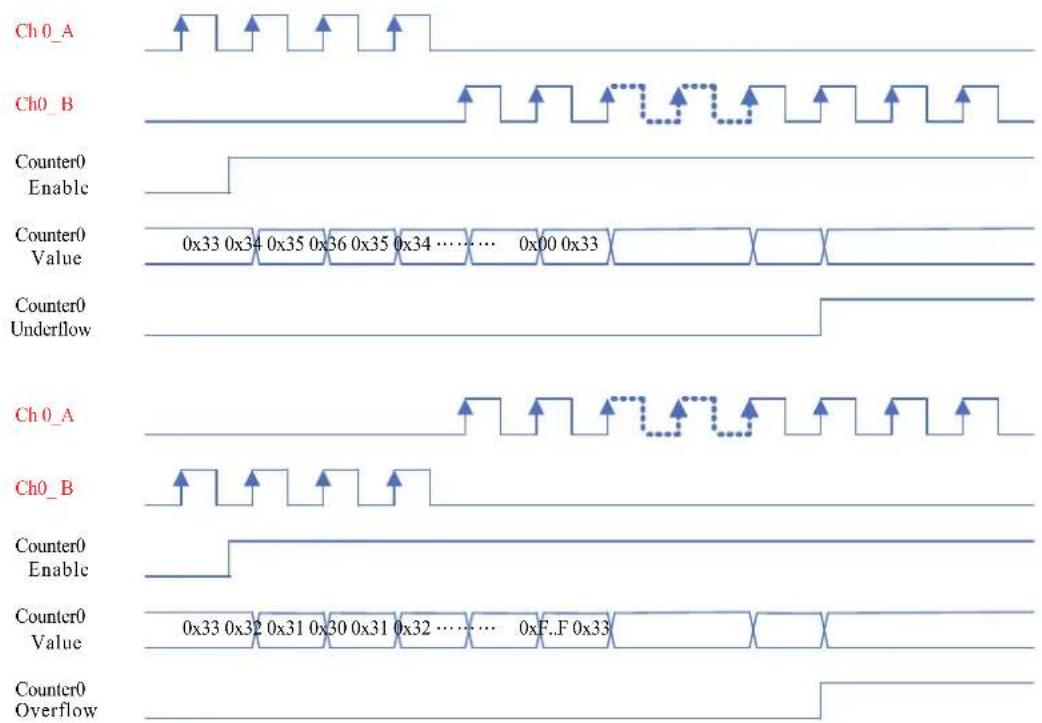
Figure 3.21 Up/Down, With Reload, Count Once
Up/Down, With Reload, Count Repetitively
Figure 3.8 shows up/down mode, Ch0_A provides the counting up function, one pulse, one up count. Ch0_B provides the counting down function, one pulse, one down count. When the counter0 is enabled, the counter0 starts to count. If the counter value is overflow or underflow, it will reset to the defined value (e.g. 0x33) and keep counting repetitively.
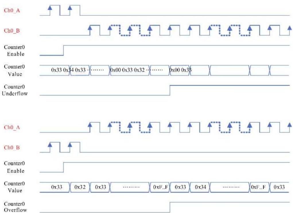
Figure 3.22 Up/Down, With Reload, Count Once
Up, No Reload, Count Once
Figure 3.9 shows counter up mode, Ch0_A provides the counting up function, one pulse, one up count. When the counter0 is enabled, the counter0 starts to count. If the counter value is overflow or underflow, it will show the minimum (0x00) or maximum (0xFFFFFFFF) value and not count continuously.

Figure 3.23 Up, No Reload, Count Once
Up, With Reload, Count Once
Figure 3.10 shows counter up mode, Ch0_A provides the counting up function, one pulse, one up count. When the counter0 is enabled, the counter0 starts to count. If the counter value is overflow or underflow, it will reset to the defined value (e.g. 0x33) but won't keep counting.

Figure 3.24 Up, With Reload, Count Once
Up, With Reload, Count Repetitively
Figure 3.11 shows up/down mode, Ch0_A provides the counting up function, one pulse, one up count. Ch0_B provides the counting down function, one pulse, one down count. When the counter0 is enabled, the counter0 starts to count. If the counter value is overflow or underflow, it will reset to the defined value (e.g. 0x33) and keep counting repetitively.
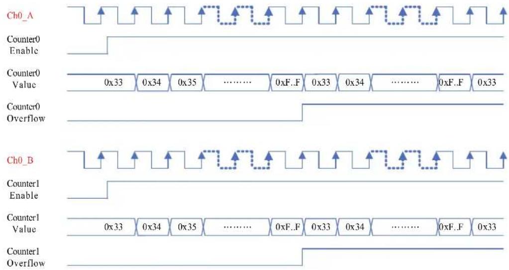
Figure 3.25 Up, With Reload, Count Repetitively
Frequency
Figure 3.12 shows the frequency function. Every counter channel can measure the frequency of assigned time window and the range is from 0.1Hz\~1MHz.

Figure 3.26 Frequency
A/B Phase 1X, No Reload, Count Once
Figure 3.13 shows A/B Phase 1X mode, Ch0_A and Ch0_B provide the counting function. When the counter0 is enabled, the counter0 starts to count. If the counter value is overflow or underflow, it will show the minimum (0x00) or maximum (0xFFFFFFF) value and not count continuously.

Figure 3.27 A/B Phase 1X, No Reload, Count Once
A/B Phase 1X, With Reload, Count Once
Figure 3.14 shows A/B Phase 1X mode, Ch0_A and Ch0_B provide the counting function. When the counter0 is enabled, the counter0 starts to count. If the counter value is overflow or underflow, it will reset to the defined value (e.g. 0x33) but won't keep counting.
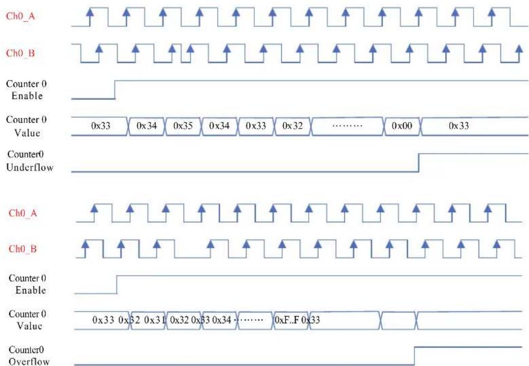
Figure 3.28 A/B Phase 1X, With Reload, Count Once
A/B Phase 1X, With Reload, Count Repetitively
Figure 3.15 shows A/B Phase 1X mode, Ch0_A and Ch0_B provide the counting function. When the counter0 is enabled, the counter0 starts to count. If the counter value is overflow or underflow, it will reset to the defined value (e.g. 0x33) and keep counting repetitively.

Figure 3.29 A/B Phase 1X, With Reload, Count Repetitively
A/B Phase 2X, No Reload, Count Once
Figure 3.16 shows A/B Phase 2X mode, Ch0_A and Ch0_B provide the counting function. When the counter0 is enabled, the counter0 starts to count. If the counter value is overflow or underflow, it will reset to the defined value (e.g. 0x33) but won't keep counting.

Figure 3.30 A/B Phase 2X, No Reload, Count Once
A/B Phase 2X, With Reload, Count Once
Figure 3.17 shows A/B Phase 2X mode, Ch0_A and Ch0_B provide the counting function. When the counter0 is enabled, the counter0 starts to count. If the counter value is overflow or underflow, it will reset to the defined value (e.g. 0x33) and keep counting repetitively.

Figure 3.31 A/B Phase 2X, With Reload, Count Once
A/B Phase 2X, With Reload, Count Repetitively
Figure 3.18 shows A/B Phase 2X mode, Ch0_A and Ch0_B provide the counting function. When the counter0 is enabled, the counter0 starts to count. If the counter value is overflow or underflow, it will reset to the defined value (e.g. 0x33) and keep counting repetitively.
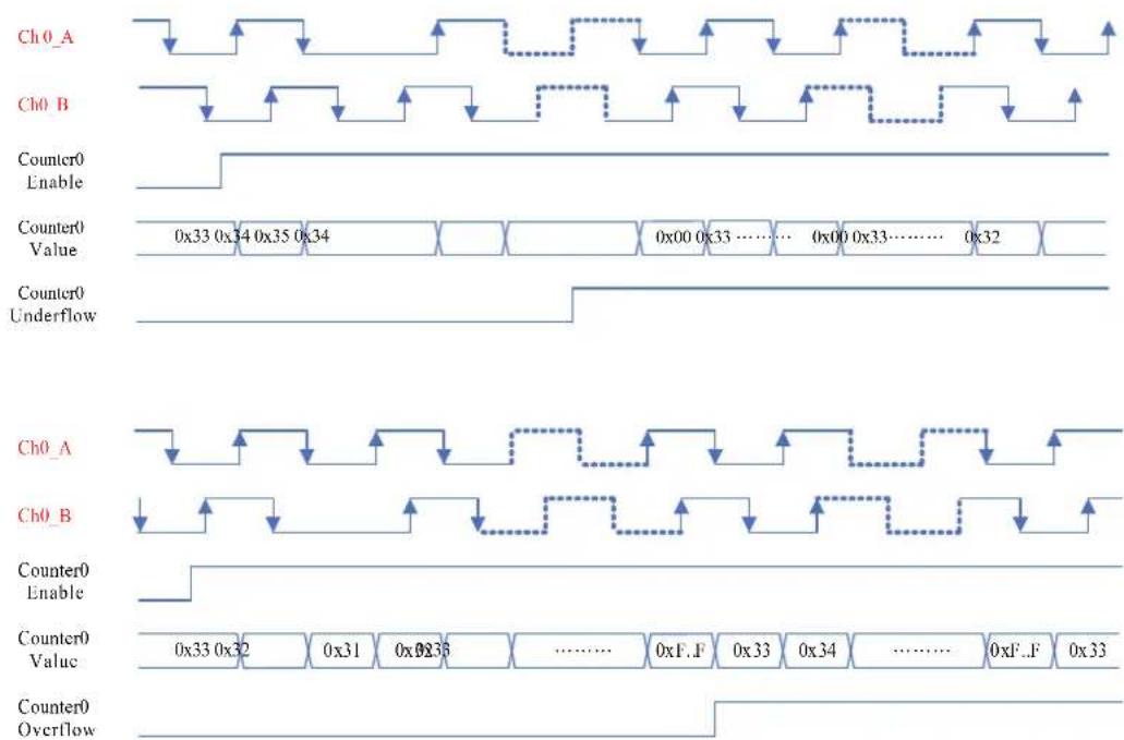
Figure 3.32 A/B Phase 2X, With Reload, Count Repetitively
A/B Phase 4X, No Reload, Count Once
Figure 3.19 shows A/B Phase 4X mode, Ch0_A and Ch0_B provide the counting function. When the counter0 is enabled, the counter0 starts to count. If the counter value is overflow or underflow, it will reset to the defined value (e.g. 0x33) but won't keep counting.

Figure 3.33 A/B Phase 4X, No Reload, Count Once
A/B Phase 4X, With Reload, Count Once
Figure 3.20 shows A/B Phase 4X mode, Ch0_A and Ch0_B provide the counting function. When the counter0 is enabled, the counter0 starts to count. If the counter value is overflow or underflow, it will reset to the defined value (e.g. 0x33) and keep counting repetitively.

Figure 3.34 A/B Phase 4X, With Reload, Count Once
A/B Phase 4X, With Reload, Count Repetitively
Figure 3.21 shows A/B Phase 2X mode, Ch0_A and Ch0_B provide the counting function. When the counter0 is enabled, the counter0 starts to count. If the counter value is overflow or underflow, it will reset to the defined value (e.g. 0x33) and keep counting repetitively.
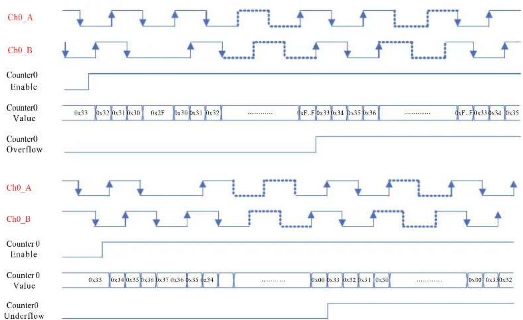
Figure 3.35 A/B Phase 4X, With Reload, Count Repetitively
DI Gate Function No Alarm
DI Gate Disable : Whatever the DI value is, the counter still continuously counts
DI Gate Enable : If the DI value is set to high, the counter can count. Otherwise, the counter will be stopped counting.
Not Retriggerable : It means DI0 only can trigger the counter to count once.
■ Retriggerable : It means DI0 can trigger the counter to count anytime.
■ High level : the DIO trigger level
■ Low level : the DIO trigger level
■ Rising Edge : the DIO trigger edge
■ Falling Edge : the DI0 trigger edge
Rising Edge Start : When DI0 status changes from low to high, the counter will start to count. After start, whatever the DI0 status, the counter still counts until the counter0 is disabled.
- Falling Edge Start: When DI0 status changes from high to low, the counter will start to count. After start, whatever the DI0 status, the counter still counts until the counter0 is disabled.
Pulse/DIR, With Reload, Count Once, DI Gate Disable
Figure 3.22 shows pulse/direction mode, Ch0_A provides the counting function, one pulse, one count. Ch0_B provides the clockwise and counter clockwise function. When the counter0 is enabled, the counter0 starts to count. If the counter value is overflow or underflow, it will show the minimum (0x00) or maximum (0xFFFFFFF) value and not count continuously. Whatever the DI value is, the counter still continuously counts.

Figure 3.36 Pulse/DIR, With Reload, Count Once, DI Gate Disable
Pulse/DIR, With Reload, Count Repetitively, DI Gate Disable
Figure 3.23 shows pulse/direction mode, Ch0_A provides the counting function, one pulse, one count. Ch0_B provides the clockwise and counter clockwise function. When the counter0 is enabled, the counter0 starts to count. If the counter value is overflow or underflow, it will reset to the defined value (e.g. 0x33) but won't keep counting. Whatever the DI value is, the counter still continuously counts.

Figure 3.37 Pulse/DIR, With Reload, Count Repetitively, DI Gate Disable
Pulse/DIR, With Reload, Count Once, DI Gate Enable, High level, Not Retriggerable
Figure 3.24 shows pulse/direction mode, Ch0_A provides the counting function, one pulse, one count. Ch0_B provides the clockwise and counter clockwise function. When the counter0 is enabled, the counter0 starts to count. If the counter value is overflow or underflow, it will reset to the defined value (e.g. 0x33) but won't keep counting. If the D10 value is high level, the counter0 will starts to count but cannot retriggered. Otherwise, the counter0 will stop counting.

Figure 3.38 Pulse/DIR, With Reload, Count Once, DI Gate Enable, High level, Not Retriggerable
Pulse/DIR, With Reload, Count Repetitively, DI Gate Enable, High level, Not Retriggerable
Figure 3.25 shows pulse/direction mode, Ch0_A provides the counting function, one pulse, one count. Ch0_B provides the clockwise and counter clockwise function. When the counter0 is enabled, the counter0 starts to count. If the counter value is overflow or underflow, t will reset to the defined value (e.g. 0x33) but won't keep counting. If the D10 value is high level, the counter0 will starts to count but cannot retriggered. Otherwise, the counter0 will stop counting.

Figure 3.39 Pulse/DIR, With Reload, Count Repetitively, DI Gate Enable, High level, Not Retriggerable
Pulse/DIR, With Reload, Count Once, DI Gate Enable, High level, Retriggerable
Figure 3.26 shows pulse/direction mode, Ch0_A provides the counting function, one pulse, one count. Ch0_B provides the clockwise and counter clockwise function. When the counter0 is enabled, the counter0 starts to count. If the counter value is overflow or underflow, it will reset to the defined value (e.g. 0x33) and keep counting repetitively.. If the DI0 value is high level, the counter0 will starts to count and can be retriggered. Otherwise, the counter0 will stop counting.

Figure 3.40 Pulse/DIR, With Reload, Count Repetitively, DI Gate Enable, High level, Not Retriggerable
Pulse/DIR, With Reload, Count Repetitively, DI Gate Enable, High level, Retriggerable
Figure 3.27 shows pulse/direction mode, Ch0_A provides the counting function, one pulse, one count. Ch0_B provides the clockwise and counter clockwise function. When the counter0 is enabled, the counter0 starts to count. If the counter value is overflow or underflow, it will reset to the defined value (e.g. 0x33) and keep counting repetitively. If the DI0 value is high level, the counter0 will starts to count and can be retriggered. Otherwise, the counter0 will stop counting.

Figure 3.41 Pulse/DIR, With Reload, Count Repetitively, DI Gate Enable, High level, Retriggerable
Pulse/DIR, With Reload, Count Once, DI Gate Enable, Low level, Not Retriggerable
Figure 3.28 shows pulse/direction mode, Ch0_A provides the counting function, one pulse, one count. Ch0_B provides the clockwise and counter clockwise function. When the counter0 is enabled, the counter0 starts to count. If the counter value is overflow or underflow, it will reset to the defined value (e.g. 0x33) but won't keep counting. If the D10 value is low level, the counter0 will starts to count but cannot retriggered. Otherwise, the counter0 will stop counting.
Figure 3.42 Pulse/DIR, With Reload, Count Repetitively, DI Gate Enable, Low level, Retriggerable
Pulse/DIR, With Reload, Count Repetitively, DI Gate Enable, Low level, Not Retriggerable
Figure 3.29 shows pulse/direction mode, Ch0_A provides the counting function, one pulse, one count. Ch0_B provides the clockwise and counter clockwise function. When the counter0 is enabled, the counter0 starts to count. If the counter value is overflow or underflow, t will reset to the defined value (e.g. 0x33) but won't keep counting. If the D10 value is low level, the counter0 will start to count but cannot be retriggered. Otherwise, the counter0 will stop counting.

Figure 3.43 Pulse/DIR, With Reload, Count Repetitively, DI Gate Enable, Low level, Not Retriggerable
Pulse/DIR, With Reload, Count Once, DI Gate Enable, Low level, Retriggerable
Figure 3.29 shows pulse/direction mode, Ch0_A provides the counting function, one pulse, one count. Ch0_B provides the clockwise and counter clockwise function. When the counter0 is enabled, the counter0 starts to count. If the counter value is overflow or underflow, it will reset to the defined value (e.g. 0x33) and keep counting repetitively. If the DI0 value is low level, the counter0 will starts to count and can be retriggered. Otherwise, the counter0 will stop counting.
Figure 3.44 Pulse/DIR, With Reload, Count Once, DI Gate Enable, Low level, Retriggerable
Pulse/DIR, With Reload, Count Repetitively, DI Gate Enable, Low level, Retriggerable
Figure 3.30 shows pulse/direction mode, Ch0_A provides the counting function, one pulse, one count. Ch0_B provides the clockwise and counter clockwise function. When the counter0 is enabled, the counter0 starts to count. If the counter value is overflow or underflow, it will reset to the defined value (e.g. 0x33) and keep counting repetitively. If the DI0 value is low level, the counter0 will starts to count and can be retriggered. Otherwise, the counter0 will stop counting.
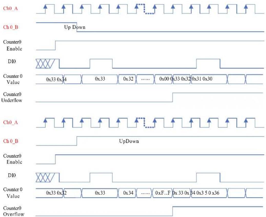
Figure 3.45 Pulse/DIR, With Reload, Count Repetitively, DI Gate Enable, Low level, Retriggerable
Pulse/DIR, With Reload, Count Once, DI Gate Enable, Rising Edge, Not Retriggerable
Figure 3.31 shows pulse/direction mode, Ch0_A provides the counting function, one pulse, one count. Ch0_B provides the clockwise and counter clockwise function. When the counter0 is enabled, the counter0 starts to count. If the counter value is overflow or underflow, it will reset to the defined value (e.g. 0x33) but won't keep counting. If the DI0 status is rising edge, the counter0 will starts to count but cannot retriggered. Otherwise, the counter0 will stop counting.

Figure 3.46 Pulse/DIR, With Reload, Count Once, DI Gate Enable, Rising Edge, Not Retriggerable
Pulse/DIR, With Reload, Count Repetitively, DI Gate Enable, Rising Edge, Not Retriggerable
Figure 3.32 shows pulse/direction mode, Ch0_A provides the counting function, one pulse, one count. Ch0_B provides the clockwise and counter clockwise function. When the counter0 is enabled, the counter0 starts to count. If the counter value is overflow or underflow, t will reset to the defined value (e.g. 0x33) but won't keep counting. If the D10 status is rising edge, the counter0 will start to count but cannot be retriggered. Otherwise, the counter0 will stop counting.

Figure 3.47 Pulse/DIR, With Reload, Count Repetitively, DI Gate Enable, Rising Edge, Not Retriggerable
Pulse/DIR, With Reload, Count Once, DI Gate Enable, Rising Edge, Retriggerable
Figure 3.33 shows pulse/direction mode, Ch0_A provides the counting function, one pulse, one count. Ch0_B provides the clockwise and counter clockwise function. When the counter0 is enabled, the counter0 starts to count. If the counter value is overflow or underflow, it will reset to the defined value (e.g. 0x33) and keep counting repetitively. If the DI0 status is rising edge, the counter0 will starts to count and can be retriggered. Otherwise, the counter0 will stop counting.
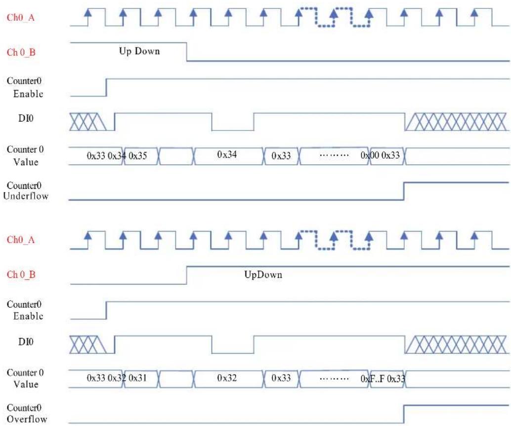
Figure 3.48 Pulse/DIR, With Reload, Count Once, DI Gate Enable, Rising Edge, Retriggerable
Pulse/DIR, With Reload, Count Repetitively, DI Gate Enable, Rising Edge, Retriggerable
Figure 3.34 shows pulse/direction mode, Ch0_A provides the counting function, one pulse, one count. Ch0_B provides the clockwise and counter clockwise function. When the counter0 is enabled, the counter0 starts to count. If the counter value is overflow or underflow, it will reset to the defined value (e.g. 0x33) and keep counting repetitively. If the D10 status is rising edge, the counter0 will starts to count and can be retriggered. Otherwise, the counter0 will stop counting.

Figure 3.49 Pulse/DIR, With Reload, Count Repetitively, DI Gate Enable, Rising Edge, Retriggerable
Pulse/DIR, With Reload, Count Once, DI Gate Enable, Falling Edge, Not Retriggerable
Figure 3.35 shows pulse/direction mode, Ch0_A provides the counting function, one pulse, one count. Ch0_B provides the clockwise and counter clockwise function. When the counter0 is enabled, the counter0 starts to count. If the counter value is overflow or underflow, it will reset to the defined value (e.g. 0x33) but won't keep counting. If the DI0 status is falling edge, the counter0 will starts to count but cannot retriggered. Otherwise, the counter0 will stop counting.

Figure 3.50 Pulse/DIR, With Reload, Count Once, DI Gate Enable, Falling Edge, Not Retriggerable
Pulse/DIR, With Reload, Count Repetitively, DI Gate Enable, Falling Edge, Not Retriggerable
Figure 3.36 shows pulse/direction mode, Ch0_A provides the counting function, one pulse, one count. Ch0_B provides the clockwise and counter clockwise function. When the counter0 is enabled, the counter0 starts to count. If the counter value is overflow or underflow, it will reset to the defined value (e.g. 0x33) and keep counting. If the DI0 status is falling edge, the counter0 will start to count but cannot be retriggered. Otherwise, the counter0 will stop counting.
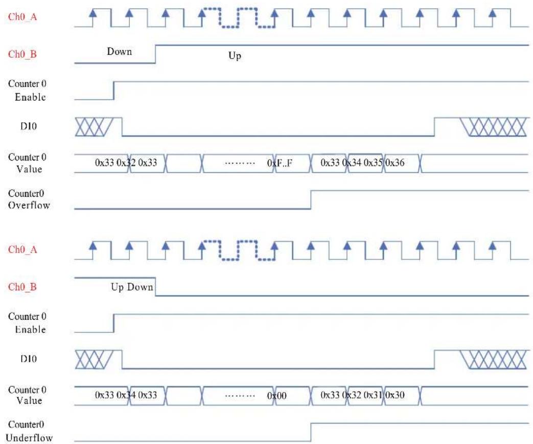
Figure 3.51 Pulse/DIR, With Reload, Count Repetitively, DI Gate Enable, Falling Edge, Not Retriggerable
Pulse/DIR, With Reload, Count Once, DI Gate Enable, Falling Edge, Retriggerable
Figure 3.37 shows pulse/direction mode, Ch0_A provides the counting function, one pulse, one count. Ch0_B provides the clockwise and counter clockwise function. When the counter0 is enabled, the counter0 starts to count. If the counter value is overflow or underflow, it will reset to the defined value (e.g. 0x33) and keep counting repetitively. If the DI0 status is falling edge, the counter0 will starts to count and can be retriggered. Otherwise, the counter0 will stop counting.

Figure 3.52 Pulse/DIR, With Reload, Count Once, DI Gate Enable, Falling Edge, Retriggerable
Pulse/DIR, With Reload, Count Repetitively, DI Gate Enable, Falling Edge, Retriggerable
Figure 3.38 shows pulse/direction mode, Ch0_A provides the counting function, one pulse, one count. Ch0_B provides the clockwise and counter clockwise function. When the counter0 is enabled, the counter0 starts to count. If the counter value is overflow or underflow, it will reset to the defined value (e.g. 0x33) and keep counting repetitively. If the DIO status is falling edge, the counter0 will starts to count and can be retriggered. Otherwise, the counter0 will stop counting.

Figure 3.53 Pulse/DIR, With Reload, Count Repetitively, DI Gate Enable, Falling Edge, Retriggerable
Pulse/DIR, With Reload, Count Once, DI Gate Enable, Rising Edge Start
Figure 3.39 shows pulse/direction mode, Ch0_A provides the counting function, one pulse, one count. Ch0_B provides the clockwise and counter clockwise function. When the counter0 is enabled, the counter0 starts to count. If the counter value is overflow or underflow, it will reset to the defined value (e.g. 0x33) but won't keep counting. If the D10 status is rising edge, the counter0 will starts to count and won't be retriggered.
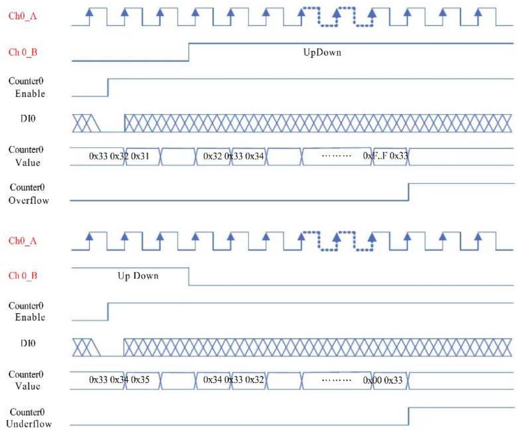
Figure 3.54 Pulse/DIR, With Reload, Count Once, DI Gate Enable, Rising Edge Start
Pulse/DIR, With Reload, Count Repetitively, DI Gate Enable, Rising Edge Start
Figure 3.40 shows pulse/direction mode, Ch0_A provides the counting function, one pulse, one count. Ch0_B provides the clockwise and counter clockwise function. When the overflow of If the DIO gered.

Figure 3.55 Pulse/DIR, With Reload, Count Repetitively, DI Gate Enable, Rising Edge Start
Pulse/DIR, With Reload, Count Once, DI Gate Enable, Falling Edge Start
Figure 3.41 shows pulse/direction mode, Ch0_A provides the counting function, one pulse, one count. Ch0_B provides the clockwise and counter clockwise function. When the counter0 is enabled, the counter0 starts to count. If the counter value is overflow or underflow, it will reset to the defined value (e.g. 0x33) but won't keep counting. If the DI0 status is falling edge, the counter0 will starts to count and won't be retriggered.

Figure 3.56 Pulse/DIR, With Reload, Count Once, DI Gate Enable, Falling Edge Start
Pulse/DIR, With Reload, Count Repetitively, DI Gate Enable, Rising Edge Start
Figure 3.42 shows pulse/direction mode, Ch0_A provides the counting function, one pulse, one count. Ch0_B provides the clockwise and counter clockwise function. When the counter0 is enabled, the counter0 starts to count. If the counter value is overflow or underflow, it will reset to the defined value (e.g. 0x33) and keep counting. If the D10 status is rising edge, the counter0 will starts to count and won't be retriggered.

Figure 3.57 Pulse/DIR, With Reload, Count Repetitively, DI Gate Enable, Rising Edge Start
DO Alarm Function No Gate
■ High Pulse: the DO original status will be low and when the counter value counts to defined alarm value, the DO status will change low to high.
Low Pulse: the DO original status will be high and when the counter value counts to defined alarm value, the DO status will change high to low.
No Auto Reload: When the counter is overflow or underflow, the value will be reset to the initial value but not count again.
■ Auto Reload: When the counter is overflow or underflow, the value will be reset to the initial value and count again.
■ High Alarm: when the counter value is greater than the assigned counter alarm value, the DO will be active.
Low Alarm: When the counter value is less than the assigned counter alarm value, the DO will be active.
Because the DI gate is disabled, whatever the DI value is, the counter still continuously counts. When the counter0 value is overflow, the value will be reset to the initial value like 0x33. Count once means if the counter0 is overflow, it won't count again.
Chapter 4
Interface Module
4.1 APAX-5490 4-port RS-232/422/485 Communication Module
The APAX-5490 is equipped with four RS232/422/485 ports, which can issue commands to control other devices. It is fully integrated with the APAX-5580 series and transmits data to through the COM port. The integrated system is an intelligent standalone system and can connect and issue commands to control devices such as printers and PLCs in remote factory location.

Figure 4.1 APAX-5490 Module Front View and connection example
APAX-5490 Specifications
Communications
Channels
COM1, COM2: RS-232/422/485 (Isolated)
COM3, COM4: RS-232/422/485 (Isolated)
Data bits: 5, 6, 7, 8
■ Stop bits: 1, 1.5, 2
Parity: none, even, odd
■ Communication Controller: EXAR XR17V354
■ Communication Speed (bps): 50 \~ 230.4kbps
Data Signals:
RS-232: TxD, RxD, GND
RS-422: TxD+, RxD+, TxD-, RxD-
RS-485: Data+, Data-
Isolation: 2500 V DC
Connector: PLUG_26_3.81mm
Environment
Operating Temperature: 0 \~ 60°C (when mounted vertically)
■ Relative Humidity: 5 \~ 95%
■ Storage Temperature: -40 \~ 70°C (non-condensing)
Configuration Settings
SW4:COM1, SW5:COM2, SW6:COM3, SW7:COM4
| SW4~7 Status Function | ||
| PIN1 | ON Force Disable RS-232 RxD | |
| OFF Enable RS-232 RxD (default) | ||
| PIN2 | ON Force Disable RS-485 RxD | |
| OFF Enable RS-485 RxD (default) | ||
| PIN3 | ON | Terminal Resistor: 120ohm(RS-422 TxD/RS-485) |
| OFF Disable (default) | ||
| PIN4 | ON Terminal Resistor: 120ohm(RS-422 RxD) | |
| OFF Disable (default) | ||
| SW3 Status Function | |
| PIN1(COM1) | ON RS-422 Master |
| OFF RS-422 Slave/RS-485 (default) | |
| PIN2(COM2) | ON RS-422 Master |
| OFF RS-422 Slave/RS-485 (default) | |
| PIN3(COM3) | ON RS-422 Master |
| OFF RS-422 Slave/RS-485 (default) | |
| PIN4(COM4) | ON RS-422 Master |
| OFF RS-422 Slave/RS-485 (default) |
4.2 APAX-5435 APAX iDoor Expansion module
The APAX-5435 is equipped with one mini PCI express, which can support Advantech iDoor module to expand 5580 interface, including filedbus and wireless communication. It is fully integrated with the APAX-5580 series. The integrated system is an intelligent standalone system and can connect and issue commands to control devices such as printers and PLCs in remote factory location.
Specifications
Module Interface
Mini PCIEPCIE 2.0
mSATA
■ Supports SATA GENI/GENII/GENIII
Environment
- Operating Temperature: -10 \~ 60°C (when mounted vertically)
■ Relative Humidity: 5 \~ 95%
■ Storage Temperature: -40 \~ 85°C (non-condensing)
Supported iDoor Modules
PCM-26D2CA SJA1000 CANBUS, CANOpen, DB9
■ PCM-26D1DB 1-Port Hilscher netX100 FieldBus mPCIe, ProfiBus, DB9
■ PCM-26R2PN 2-Port Hilscher netX100 FieldBus mPCIe, PROFINET, RJ45
■ PCM-26R2EC 2-Port Hilscher netX100 FieldBus mPCIe, EtherCAT, RJ45
■ PCM-26R2EI 2-Port Hilscher netX100 FieldBus mPCIe, EtherNet/IP, RJ45
■ PCM-24S2WF Wi-Fi 802.11 a/b/g/n 2T2R w/ Bluetooth4.0, Half-size mPCIe, 2-port SMA
■ PCM-24S33G Wide-Temp 3.75G HSPA and GPS, 2-in-1, Full-size mPCIe w/ dual SIM Card holder, Antenna, cable
■ PCM-24R2GL 2-port GbE BaseT(X) 10/100/1000 Mbps, mPCIe Card
■ PCM-24R2PE GbE, IEEE 802.3af (PoE) Compliant, mPCIe, RJ45 x2
■ PCM-24R1TP Intel 82574L, GbE, RJ45 x 1
■ PCM-23U1DG USB Slot w/ Lock for USB Dongle, Half-size mPCIe
■ PCM-2300MR MRAM, 2 MByte
Note!
Make sure the system is powered off when you want to setup the APAX-5435 with APAX-5580. The APAX-5435 doesn't support hot swap.

Configuration Settings
SW2
| mPCIe Mode(default) SATA Mode | |||
| SW2 PIN1 ON ON | |||
| PIN2 ON OFF | |||
4.3 APAX-5090 4-port RS-232/422/485 Communication Module
The APAX-5090 is equipped with four RS232/422/485 ports, which can issue commands to control other devices. It is fully integrated with the APAX-5580 series and transmits data to through the COM port. APAX-5090 communicate with APAX-5580 by APAX local bus, means it can support distributed topology by APAX bus.
APAX-5090 Specifications
Communications
Interface
COM 1, COM 2: RS-232/422/485*
COM 3, COM 4: RS-232/422/485*
* Change Mode with the switch
Data Bits: 8
■ Stop Bits: 1, 1.5, 2
Parity: None
Baud Rate: 600bps\~115.2 kbps
Data Signals:
RS-232: TxD, RxD, GND
RS-422: TxD+, RxD+, TxD-, RxD
RS-485: Data+, Data-
FIFO: 256 bytes
■ Operation Mode: Virtual COM
■ Maximum Support: Up to 8 pcs with one controller
Protection
■ ESD Protection: 15 kV
■ EFT Protection: 2,500 VDC
Isolation Protection:2500 VDC (between COM port and backplane)
Note!The APAX-5090 doesn't support hot swap.

The APAX-5090 have to be used with APAX-5402L-E2A2AE
Pin assignment


Configuration Settings
SW4:COM1, SW5:COM2, SW6:COM3, SW7:COM4
| SW4~7 Status Function | ||
| PIN1 ON Force Dis | isable RS-232 | RxD |
| OFF Enable RS-232 RxD (default) | ||
| PIN2 ON Force Dis | isable RS-485 | RxD |
| OFF Enable RS-485 RxD (default) | ||
| PIN3 ON Terminal | Resistor: 120 | ohm(RS-422 TxD/RS-485) |
| OFF Disable (default) | ||
| PIN4 ON Terminal | Resistor: 120 | ohm(RS-422 RxD) |
| OFF Disable (default) | ||
| SW8 Status Function | |
| PIN1 (COM1) | ON RS-422 Master |
| OFF RS-422 Slave/RS-485 (default) | |
| PIN2 (COM2) | ON RS-422 Master |
| OFF RS-422 Slave/RS-485 (default) | |
| PIN3 (COM3) | ON RS-422 Master |
| OFF RS-422 Slave/RS-485 (default) | |
| PIN4 (COM4) | ON RS-422 Master |
| OFF RS-422 Slave/RS-485 (default) |
4.4 APAX-5430 SATA Interface Module
APAX-5430 is a SATA interface module providing SATA SSD installation to an APAX system. User can install one 2.5" HDD/SSD on the APAX-5430 module and then attach to the APAX-5580 system. Two APAX-5430 modules can be installed on one system and function as RAID 0/1 through the configuration in BIOS.
Note!
APAX is a DIN-Rail Mounted system, do not recommend using HDD which is spindle component on these environment. Highly recommend using SSD which is without spindle component, which would help system gaining better reliability.

4.4.1 Specification
4.4.1.1 Function
Interface: SATA
RAID: Supports RAID 0/1
■ Support SATA I/II/III 2.5" SSD
■ Power control switch for safe swapping
4.4.1.2 Environment
Operating Temperature: -10 \~ 60°C (when mounted vertically)
■ Storage Temperature: -40 \~ 70°C
■ Relative Humidity: 5 \~ 95% (non-condensing)
4.4.2 Installation Process
Please follow below steps for the SSD installation
- Remove the screws on the front panel and release the lock on the upper and bottom side, and then remove the PCB out from the APAX IO case.
- Plug the SATA SSD into the SATA connector and fix it with the 4x screws provided.
- Insert the PCB into the case and fix it with 2 screws on the front panel.
- Power off the system and plug the module into the APAX-5402 series backplane

4.4.3 Setup RAID function in BIOS
- Enter the BIOS and choose the "Advanced" tab and select SATA Configuration

- In the item SATA Mode Selection and select "RAID" to enable the Activate the RAID function

- Reboot the system and enter the RAID option ROM by, pressing "Ctrl + I"

- Select Create RAID Volume to create RAID mode
![Intel(R) Matrix Storage Manager option ROM v8.5.8.1038 ICH18R/DO uRAIDS Copyright(C) 2003-08 Intel Corporation. All Rights Reserved. [ MAIN MENU ] 1. Create RAID Volume 2. Delete RAID Volume 3. Reset Disks to Non-RAID 4. Recovery Volume Options 5. Exit [ DISK/VOLUME INFORMATION ] RAID Volumes: None…](/content/2026/05/1083884/images/8e8826bf88dc134e75307c283f0994a7c373591f93377a9982833847421d5e7c.jpg)
5. Enter a name
![Intel(R) Matrix Storage Manager option ROM v8.5.0.1838 ICH10R/DO wRA10S Copyright(C) 2003-08 Intel Corporation. All Rights Reserved. [ CREATE VOLUME MENU ] Name: Raid_0 RAID Level: RAID0(Stripe) Disks: Select Disks Strip Size: 128KB Capacity: 0.0 GB Sync: N/A Create Volume [ HELP ] Enter a unique vo…](/content/2026/05/1083884/images/20ec5777a0092443404be15b2b88ed99824b4d49877483429946a304472afd13.jpg)
6. Select the RAID mode in the RAID Level.
![Intel(R) Matrix Storage Manager option ROM v8.5.0.1030 ICH10R/DO uRAIDS Copyright(C) 2003-08 Intel Corporation. All Rights Reserved. [ CREATE VOLUME MENU ] Name: RAID 0 RAID Level: 纸10B(Stripe) Disk: Select Disk Strip Size: 120KB Capacity: 0.0 GB Sync: N/A Create Volume [ HELP ] Choose the RAID leve…](/content/2026/05/1083884/images/be286fe95707ab2958d11feac3cf362fb48ec3c61c1a85a39c82aff356a466f6.jpg)
7. Select Disks
![Intel(R) Matrix Storage Manager option ROM v8.5.0.1838 ICH10R/DO uRA10S Copyright(C) 2003-08 Intel Corporation. All Rights Reserved. [ CREATE VOLUME MENU ] Name: Raid_0 RAIP Level: RAID(Stripe) Disks: Select Disks Strip Size: 120KB Capacity: 0.0 GB Sync: N/A Create Volume [ HELP ] Press ENTER to sel…](/content/2026/05/1083884/images/b1f2514bfe8767567de693a014048e24423b5811110159c8464f2ccd82259349.jpg)
![None: Raid_0 RAID Level: RAID0(Stripe) [ SELECT DISKS ] Port Drive Model Serial ■ Size Status 1 ADC WD0000AJS-00B4A0 WD-RMAT22252009 74.5GB Non-RATD Disk 1 ADC WD0000AJS-00B4A0 WD-RMAT22348914 74.5GB Non-RATD Disk 2 ADC WD0000AJS-00B4A0 WD-RMAT22252145 74.5GB Non-RATD Disk 3 ADC WD0000AJS-00B4A0 WD-…](/content/2026/05/1083884/images/cd6feb854e2aecd7cb565c5520408317ff43d2574b9b16546c2a73af265b2605.jpg)
- Finish the setting and Enter the "Create Volume", And Y to create the volume.
![Intel(R) Matrix Storage Manager option ROM v8.5.0.1038 ICH10R/00 wRAIDS Copyright(C) 2003-08 Intel Corporation. All Rights Reserved. [ CREATE VOLUME MENU ] Name: Raid_0 RAID Level: RAID0(Stripe) Disks: Select Disks Strip Size: 128KB Capacity: 149.1 GB Sync: N/A Create Volume [ HELP ] Press ENTER to…](/content/2026/05/1083884/images/717e38958854d46e79238861b6bb91404b27178a39fcb916471ea14c19a9ec8a.jpg)
![Intel(R) Matrix Storage Manager option ROM v8.5.8.1838 ICH18R/00 uRAIDS Copyright(C) 2003-08 Intel Corporation. All Rights Reserved. [ WRITE VOLUME MIN] Name: Raid_0 RAID Level: RAID0(Stripe) Disks: Select Disks Strip Size: 120KB Capacity: 149.1 GB Sync: N/A WARNING: ALL DATA IN SELECTED DISKS WILL…](/content/2026/05/1083884/images/d9f5344f154ddf355028014774b92c0d48fd93c6ab7e6d27b2b7e9f6812e06b6.jpg)
9. Save and Exit
![Intel(R) Matrix Storage Manager option ROM v8.5.0.1830 ICH10R/DO uRAIDS Copyright(C) 2003-08 Intel Corporation. All Rights Reserved. [ MAIN MENU ] 1. Create RAID Volume 2. Delete RAID Volume 3. Reset Disks to Non-RAID 4. Recovery Volume Options 5. Exit [ DISK/VOLUME INFORMATION ] RAID Volumes: ID Na…](/content/2026/05/1083884/images/c67d3cc1f2a039ffaa959e60f9535159d578160df4185e7ff93590164c3c185a.jpg)
![Intel(R) Matrix Storage Manager option ROM v8.5.0.1838 ICH10R/DO uRAID Copyright(C) 2003-00 Intel Corporation. All Rights Reserved. [ RAIN RAIN ] 1. Create RAID Volume 3. Reset Disks to Non-RAID 2. Delete RAID Volume 4. Recovery Volume Options 5. Exit [ DISK-VOLUME INFORMATION ] RAID Volumes: ID Nam…](/content/2026/05/1083884/images/89b4567b2ae3c1e4a2f6d8ab13ef981fdcde979342b6fb1f645c0ff87eff2bbf.jpg)
Chapter 5
Backplane Modules
5.1 APAX-5002/5002L 2-slot Backplane Module
APAX-5002/5002L is an interface between CPU module, coupler and I/O modules. Different APAX-5002/5002L can be stacked together. Power and data can be transferred to I/O modules inserted on the APAX-5002/5002L. You can use external power supply or APAX-5343E power supply module to give power to the backplanes and I/O modules. But only APAX-5002 equips the screw terminal for the external power supply wiring. Refer to Section 1.7.1 and 1.7.2 for the operation procedure.
There is an expansion port on front side of APAX-5002 (APAX-5002L is not equipped with this feature). With this port, users can build a remote expansion architecture, remaining fast local-bus data transmission speed. Standard Ethernet cables can be used to connect any two APAX-5002. However, shielded industrial Ethernet cable MUST be used instead of standard Ethernet cable when the system is used in harsh environment, such as factory automation. Unmanaged industrial Ethernet switches (such as Advantech EKI-2528) with 100 Mbps transmission speed can also be used between two APAX-5002. Therefore, you can flexibly build any remote expansion with line, tree or star topology. All the APAX-5000 I/O modules can benefit from the remote expansion architecture with local bus speed.
Warning!1. DO NOT use managed switch, hub or router between backplanes for expansion.

- The network for the expansion should be a local network, NOT to connect with other external network (such as public network in enterprise network, including Internet).
- Cat 6 Ethernet cable is strongly recommended for better data transmission quality.
- It is suggested to power on all the I/O modules together to avoid any unpredictable situation.
APAX-5002 Specifications
Environment
Operating Temperature: APAX-5002: -10\~60°C
APAX-5002L: -20\~70°C
Storage Temperature: APAX-5002: -40\~70°C
APAX-5002L: -40\~85°C
■ Relative Humidity: 5 \~ 95% (non-condensing)
■ Shock Resistance: 20 G @ wall mounting, duration 11 ms (tested to IEC 60068 2-27)
Vibration Resistance: 2 Grms @ wall mounting, random, 5 \~ 500 Hz, 3-axes, 1 hr/axis. (Tested to IEC 60068-2-64)
General
■ Dimensions (W x H x D): 54 x 151 x 38 mm
Weight: 120 g
■ Mounting: DIN-rail, wall (panel)
Power Input: 24 VDC*
■ Power Consumption: 1.3 W @ 24 VDC
*: When you stack more than one APAX-5002 backplanes together, there could be more than one power supplies connected to different backplane.
5.2 APAX-5001 1-slot Backplane Module
APAX-5001 functionality is the same as APAX-5002. And it is used to be connected at the right side of APAX-5002 when the total I/O module number is odd. Power and data can be transferred to I/O modules inserted on the APAX-5001. If the APAX-5001 is power-on, you can see the LED lit on to indicate the module is working well.
APAX-5001 Specifications
Environment
■ Operating Temperature: -10 \~ 60°C
■ Storage Temperature: -40 \~ 70°C
■ Relative Humidity: 5 \~ 95% (non-condensing)
■ Shock Resistance: 20 G @ wall mounting, duration 11 ms (tested to IEC 60068 2-27)
Vibration Resistance: 2 Grms @ wall mounting, random, 5 \~ 500 Hz, 3-axes, 1 hr/axis. (Tested to IEC 60068-2-64)
General
■ Dimensions (W x H x D): 28 x 151 x 38 mm
Weight: 70 g
■ Mounting: DIN-rail, wall (panel)
Power Input: 24 VDC
■ Power Consumption: 0.3 W @ 24 VDC
Chapter 6
Power Supply Modules
6.1 APAX-5343E Power Supply for Expansion Modules
APAX-5343E Specifications
Input
■ Rated Voltage: 115/230 VAC
■ Voltage Range: 90 \~ 264 VAC
■ Input Current: 1.5 A (at rated load)
■ Input Frequency Range: 47 \~ 63 Hz
Inrush Current: 50 A (one cycle at 25°C)
■ Installed Input Fuse: F 3.15 A/250 V (not accessible)
Output
■ Output Power: 72 watts
■ Power Loss at rated load: approximated 8 \~ 9 W
■ Residual Ripple: <240 mVpp
■ Startup Delay: < 3 second
Rated Voltage: 24 VDC
■ Voltage Rise: typical 60 ms
■ Rated Output Current: 3 A
■ Output Current Limitation: 3.5 \~ 4.3 A
■ Efficiency: > 87% (at 115/230 VAC Input Voltage, Rated load)
Protection
■ Isolation Protection (In/Out): 42/42 VDC
Over Voltage Protection: Shutdown at approx. 25\~27 VDC, latch off mode
■ Over Load Protection: Auto-recovery mode
■ Short Circuit Protection: Auto-recovery mode
General
■ Certifications: CE, FCC Class A, UL 508 (UL/cUL approval), Energy Star
■ Enclosure: ABS + PC
■ Diagnostics LEDs: 1 x Power
■ Dimensions (W x H x D): 75 x 151 x 115 mm
■ Operating Temperature: -10 \~ 55° C
■ Storage Temperature: -20 \~ 70°C
■ Relative Humidity: 5 \~ 95% (non-condensing)
■ Leakage Current: < 3.5 mA
Note! Refer to Section 1.7.2 for how to assembly APAX-5343E with APAX-5000 I/O modules.

6.2 APAX-5342 48VDC Power Supply for APAX-5580 series
6.2.1 Product Specifications
Input
Rated Voltage: 48 VDC
■ Voltage Range: 36\~58 VDC
■ Rated Input Current: 2.2A (Max.) @48 VDC
Output
■ Output Power: 96 W
■ Efficiency: >88% (at rated load)
Rated Voltage: 24 VDC
■ Rated Output Current: 4A
■ Output Current Limit: 4.8 A
■ Reverse voltage Protection (RVP)Yes
■ Shout Circuit ProtectionYes
Input Protection
■ Over Voltage Protection (OVP): 58 VDC
■ Under voltage protection (UVP): 36 VDC
■ Over current protection (OCP):3.33 A
Output Protection
■ Over Current Protection (OCP): 4.8A
■ Shout Circuit Protection: Yes
6.2.2 Wiring
For the power input wiring, you need to remove the upper cover:
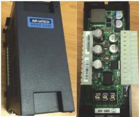
You will find three pins connect with label 48V, GND (0V) and earth ground. After screwed your power cable, you can mount this backplane with 5580 first. Please note that keep your power status in off. And then put the cover back to finish the whole installation.

6.2.3 Connectors
The right side: Connects to APAX-5580
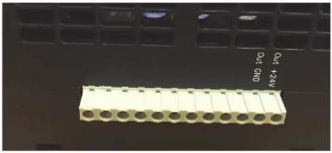
The left side: N/A

Chapter 6
Error Handling and Diagnostics
6.1 Error Handling and Diagnostics
There is one power LED on the front panel of any APAX-5000 I/O module. When the module is power-on, the LED will be lit. For analog I/O module, the LED color is green. For digital I/O module, the LED color is green or orange, depending on the module ID number. Refer to Section 1.6 for more details. Except for showing the module power status and ID number, this LED is also designed to diagnose module status.
■ LED continues flashing one time every 2 seconds

Representation: The I/O modules has problem itself
Solution: 1. Download latest firmware again to see if it works well.
- If the LED continues flashing after updating firmware, then you need to contact Advantech for technical support.
■ LED continues flashing 2 times every 2 seconds

Representation: The I/O modules has communication problem
Solution: 1. Check if the controller or coupler is installed and power-on.
-
If controller or coupler is installed, check if the Ethernet connection is broken when you have remote expansion.
-
If the networking is okay (or there is remote expansion in the system), check if any backplane is broken.
-
If backplanes are all fine, download latest firmware again to see if it works well.
-
If the LED continues flashing after updating firmware, then you need to contact Advantech for support.
■ LED continues flashing 4 times every 2 seconds

Representation: ID number of that I/O module conflicts with ID number of another I/O module
Solution: 1. Check ID number of all I/O modules in the same system.
Adjust the ID number to avoid different I/O modules with the same ID number. Refer to Section 1.6 for how to adjust ID number. Then reboot the system and it should work fine. (The LED should stop flashing)
- If the LED continues flashing after you have adjusted the ID number, then you need to contact Advantech for technical support.
www.advantech.com
Please verify specifications before quoting. This guide is intended for reference purposes only.
All product specifications are subject to change without notice.
No part of this publication may be reproduced in any form or by any means, such as electronically, by photocopying, recording, or otherwise, without prior written permission from the publisher.
All brand and product names are trademarks or registered trademarks of their respective companies.
© Advantech Co., Ltd. 2017
- APAX-5000 SERIES
- COPYRIGHT
- ACKNOWLEDGEMENTS
- PRODUCT WARRANTY (2 YEARS)
- DECLARATION OF CONFORMITY
- CE
- FCC CLASS A
- FM
- TECHNICAL SUPPORT AND ASSISTANCE
- SAFETY PRECAUTION - STATIC ELECTRICITY
- SAFETY INSTRUCTIONS
- CONTENTS
- CHAPTER 1 OVERVIEW......1
- CHAPTER 2 ANALOG INPUT/OUTPUT MODULES .....25
- CHAPTER 3 DIGITAL INPUT/OUTPUT MODULES .....41
- CHAPTER 4 INTERFACE MODULE....103
- CHAPTER 5 BACKPLANE MODULES ......117
- CHAPTER 6 POWER SUPPLY MODULES ......121
- CHAPTER 6 ERROR HANDLING AND DIAGNOSTICS.....127
- CHAPTER 1
- 1.1 INTRODUCTION
- 1.2 I/O WIRING
- 1.3 REMOVING THE I/O TERMINAL
- WARNING
- 1.4 LABELING THE TERMINAL
- 1.5 JUMPER SETTINGS
- 1.6 ID SWITCH SETTING
- 1.7 MECHANICAL ASSEMBLY AND POWER CONNECTION
- 1.7.1 WIRING POWER INPUT TO THE BACKPLANE
- NOTE
- 1.7.2 USING THE APAX-5343E POWER SUPPLY MODULE
- 1.8 DECOMMISSION AND DISPOSAL
- 1.9 MOUNTING
- 1.9.1 DIN-RAIL MOUNTING
- 1.9.2 WALL (PANEL) MOUNTING
- CHAPTER 2
- 2.1 ANALOG INPUT MODULES
- 2.1.1 APAX-5013 8-CH RTD MODULE
- APPLICATION WIRING
- APAX-5013 TECHNICAL SPECIFICATIONS
- CHANNELS: 8
- PROTECTION
- ENVIRONMENT
- GENERAL
- 2.1.2 APAX-5017 12-CH ANALOG INPUT MODULE
- TECHNICAL SPECIFICATIONS OF APAX-5017
- 2.1.3 APAX-5017H 12-CH HIGH SPEED ANALOG INPUT MODULE
- APAX-5017H SPECIFICATIONS
- 2.1.4 APAX-5018 12-CH THERMOCOUPLE INPUT MODULE
- APAX-5018 SPECIFICATIONS
- 2.1.5 APAX-5017PE 12-CH ANALOG INPUT MODULE FOR P&E APPLICATIONS
- TECHNICAL SPECIFICATIONS OF APAX-5017PE
- 2.2 ANALOG OUTPUT MODULES
- 2.2.1 APAX-5028 8-CH ANALOG OUTPUT MODULE
- 2.2.2 APAX-5028 SPECIFICATIONS
- CHAPTER 3
- DIGITAL INPUT/OUTPUT MODULES
- 3.1 DIGITAL INPUT/OUTPUT MODULES
- 3.1.1 APAX-5040 24-CH DIGITAL INPUT MODULE
- APAX-5040 SPECIFICATIONS
- DIGITAL INPUT
- 3.1.2 APAX-5045 24-CH DIGITAL INPUT/OUTPUT MODULE
- APAX-5045 SPECIFICATIONS
- DIGITAL OUTPUT
- 3.1.3 APAX-5046 24-CH DIGITAL OUTPUT MODULE
- APAX-5046 SPECIFICATIONS
- 3.1.4 APAX-5040PE 24-CH DIGITAL INPUT MODULE FOR P&E APPLICATIONS
- 3.1.5 APAX-5046SO 20-CH DIGITAL OUTPUT MODULE
- APAX-5046SO SPECIFICATIONS
- 3.2 RELAY OUTPUT MODULES
- 3.2.1 APAX-5060 12-CH RELAY OUTPUT MODULE
- APAX-5060 SPECIFICATIONS
- RELAY OUTPUT
- 3.2.2 APAX-5060PE 12-CH RELAY OUTPUT MODULE FOR P&E APPLICATIONS
- APAX-5060PE SPECIFICATIONS
- 3.3 COUNTER MODULES
- 3.3.1 APAX-5080 COUNTER/FREQUENCY AND DIO MODULE
- APAX-5080 SPECIFICATIONS
- COUNTER INPUT
- APAX-5080 COUNTER MODE NO GATE NO ALARM
- PULSE/DIR, NO RELOAD, COUNT ONCE
- PULSE/DIR, WITH RELOAD, COUNT ONCE
- PULSE/DIR, WITH RELOAD, COUNT REPETITIVELY
- UP/DOWN, NO RELOAD, COUNT ONCE
- UP/DOWN, WITH RELOAD, COUNT ONCE
- UP/DOWN, WITH RELOAD, COUNT REPETITIVELY
- UP, NO RELOAD, COUNT ONCE
- UP, WITH RELOAD, COUNT ONCE
- UP, WITH RELOAD, COUNT REPETITIVELY
- FREQUENCY
- A/B PHASE 1X, NO RELOAD, COUNT ONCE
- A/B PHASE 1X, WITH RELOAD, COUNT ONCE
- A/B PHASE 1X, WITH RELOAD, COUNT REPETITIVELY
- A/B PHASE 2X, NO RELOAD, COUNT ONCE
- A/B PHASE 2X, WITH RELOAD, COUNT ONCE
- A/B PHASE 2X, WITH RELOAD, COUNT REPETITIVELY
- A/B PHASE 4X, NO RELOAD, COUNT ONCE
- A/B PHASE 4X, WITH RELOAD, COUNT ONCE
- A/B PHASE 4X, WITH RELOAD, COUNT REPETITIVELY
- DI GATE FUNCTION NO ALARM
- PULSE/DIR, WITH RELOAD, COUNT ONCE, DI GATE DISABLE
- PULSE/DIR, WITH RELOAD, COUNT REPETITIVELY, DI GATE DISABLE
- PULSE/DIR, WITH RELOAD, COUNT ONCE, DI GATE ENABLE, HIGH LEVEL, NOT RETRIGGERABLE
- PULSE/DIR, WITH RELOAD, COUNT REPETITIVELY, DI GATE ENABLE, HIGH LEVEL, NOT RETRIGGERABLE
- PULSE/DIR, WITH RELOAD, COUNT ONCE, DI GATE ENABLE, HIGH LEVEL, RETRIGGERABLE
- PULSE/DIR, WITH RELOAD, COUNT REPETITIVELY, DI GATE ENABLE, HIGH LEVEL, RETRIGGERABLE
- PULSE/DIR, WITH RELOAD, COUNT ONCE, DI GATE ENABLE, LOW LEVEL, NOT RETRIGGERABLE
- PULSE/DIR, WITH RELOAD, COUNT REPETITIVELY, DI GATE ENABLE, LOW LEVEL, NOT RETRIGGERABLE
- PULSE/DIR, WITH RELOAD, COUNT ONCE, DI GATE ENABLE, LOW LEVEL, RETRIGGERABLE
- PULSE/DIR, WITH RELOAD, COUNT REPETITIVELY, DI GATE ENABLE, LOW LEVEL, RETRIGGERABLE
- PULSE/DIR, WITH RELOAD, COUNT ONCE, DI GATE ENABLE, RISING EDGE, NOT RETRIGGERABLE
- PULSE/DIR, WITH RELOAD, COUNT REPETITIVELY, DI GATE ENABLE, RISING EDGE, NOT RETRIGGERABLE
- PULSE/DIR, WITH RELOAD, COUNT ONCE, DI GATE ENABLE, RISING EDGE, RETRIGGERABLE
- PULSE/DIR, WITH RELOAD, COUNT REPETITIVELY, DI GATE ENABLE, RISING EDGE, RETRIGGERABLE
- PULSE/DIR, WITH RELOAD, COUNT ONCE, DI GATE ENABLE, FALLING EDGE, NOT RETRIGGERABLE
- PULSE/DIR, WITH RELOAD, COUNT REPETITIVELY, DI GATE ENABLE, FALLING EDGE, NOT RETRIGGERABLE
- PULSE/DIR, WITH RELOAD, COUNT ONCE, DI GATE ENABLE, FALLING EDGE, RETRIGGERABLE
- PULSE/DIR, WITH RELOAD, COUNT REPETITIVELY, DI GATE ENABLE, FALLING EDGE, RETRIGGERABLE
- PULSE/DIR, WITH RELOAD, COUNT ONCE, DI GATE ENABLE, RISING EDGE START
- PULSE/DIR, WITH RELOAD, COUNT REPETITIVELY, DI GATE ENABLE, RISING EDGE START
- PULSE/DIR, WITH RELOAD, COUNT ONCE, DI GATE ENABLE, FALLING EDGE START
- DO ALARM FUNCTION NO GATE
- CHAPTER 4
- 4.1 APAX-5490 4-PORT RS-232/422/485 COMMUNICATION MODULE
- APAX-5490 SPECIFICATIONS
- COMMUNICATIONS
- CONFIGURATION SETTINGS
- 4.2 APAX-5435 APAX IDOOR EXPANSION MODULE
- SPECIFICATIONS
- MODULE INTERFACE
- SUPPORTED IDOOR MODULES
- 4.3 APAX-5090 4-PORT RS-232/422/485 COMMUNICATION MODULE
- APAX-5090 SPECIFICATIONS
- INTERFACE
- DATA BITS: 8
- STOP BITS: 1, 1.5, 2
- PARITY: NONE
- BAUD RATE: 600BPS\~115.2 KBPS
- DATA SIGNALS
- FIFO: 256 BYTES
- OPERATION MODE: VIRTUAL COM
- MAXIMUM SUPPORT: UP TO 8 PCS WITH ONE CONTROLLER
- ESD PROTECTION: 15 KV
- EFT PROTECTION: 2,500 VDC
- ISOLATION PROTECTION:2500 VDC (BETWEEN COM PORT AND BACKPLANE)
- PIN ASSIGNMENT
- 4.4 APAX-5430 SATA INTERFACE MODULE
- 4.4.1 SPECIFICATION
- 4.4.1.1 FUNCTION
- 4.4.1.2 ENVIRONMENT
- 4.4.2 INSTALLATION PROCESS
- 4.4.3 SETUP RAID FUNCTION IN BIOS
- ENTER A NAME
- SELECT THE RAID MODE IN THE RAID LEVEL
- SELECT DISKS
- SAVE AND EXIT
- CHAPTER 5
- 5.1 APAX-5002/5002L 2-SLOT BACKPLANE MODULE
- APAX-5002 SPECIFICATIONS
- 5.2 APAX-5001 1-SLOT BACKPLANE MODULE
- APAX-5001 SPECIFICATIONS
- CHAPTER 6
- POWER SUPPLY MODULES
- 6.1 APAX-5343E POWER SUPPLY FOR EXPANSION MODULES
- INPUT
- OUTPUT
- 6.2 APAX-5342 48VDC POWER SUPPLY FOR APAX-5580 SERIES
- 6.2.1 PRODUCT SPECIFICATIONS
- INPUT PROTECTION
- OUTPUT PROTECTION
- 6.2.2 WIRING
- 6.2.3 CONNECTORS
- 6.1 ERROR HANDLING AND DIAGNOSTICS
- WWW.ADVANTECH.COM
Brand : Advantech
Model : APAX-5080-AE
Category : Input/Output Modules