
HDFA-200 - Optical Adapter SONY - Free user manual and instructions
Find the device manual for free HDFA-200 SONY in PDF.


| Product Type | Optical Adapter |
| Brand | Sony |
| Model | HDFA-200 |
| Connector Type | Toslink (Optical) |
| Dimensions (W x H x D) | 50 mm x 30 mm x 15 mm |
| Weight | 20 g |
| Material | Plastic with metal connectors |
| Power Supply | None (passive device) |
| Signal Type | Digital optical audio |
| Supported Sample Rates | Up to 96 kHz |
| Maximum Cable Length | 5 m (with standard fiber) |
| Insertion Loss | < 0.5 dB |
| Operating Temperature | 0°C to 40°C |
| Storage Temperature | -20°C to 60°C |
| Key Functions | Converts optical audio signals between devices |
| Maintenance | Clean with dry, lint-free cloth; avoid liquids |
| Safety Precautions | Do not bend fiber cable sharply; keep away from heat sources |
| Spare Parts | None; non-serviceable by user |
| Compatibility | Sony devices with optical output; also works with standard Toslink equipment |
| Certifications | CE, RoHS |
Frequently Asked Questions - HDFA-200 SONY
User questions about HDFA-200 SONY
0 question about this device. Answer the ones you know or ask your own.
Ask a new question about this device
Download the instructions for your Optical Adapter in PDF format for free! Find your manual HDFA-200 - SONY and take your electronic device back in hand. On this page are published all the documents necessary for the use of your device. HDFA-200 by SONY.
USER MANUAL HDFA-200 SONY
Before operating the unit, please read this manual thoroughly and retain it for future reference.
WARNING
To reduce the risk of fire or electric shock, do not expose this apparatus to rain or moisture.
To avoid electrical shock, do not open the cabinet. Refer servicing to qualified personnel only.
AVERTISSEMENT
For the customers in the U.S.A.
This equipment has been tested and found to comply with the limits for a Class A digital device, pursuant to Part 15 of the FCC Rules. These limits are designed to provide reasonable protection against harmful interference when the equipment is operated in a commercial environment. This equipment generates, uses, and can radiate radio frequency energy and, if not installed and used in accordance with the instruction manual, may cause harmful interference to radio communications. Operation of this equipment in a residential area is likely to cause harmful interference in which case the user will be required to correct the interference at his own expense.
You are cautioned that any changes or modifications not expressly approved in this manual could void your authority to operate this equipment.
All interface cables used to connect peripherals must be shielded in order to comply with the limits for a digital device pursuant to Subpart B of Part 15 of FCC Rules.
This device complies with Part 15 of the FCC Rules. Operation is subject to the following two conditions: (1) this device may not cause harmful interference, and (2) this device must accept any interference received, including interference that may cause undesired operation.
For the customers in Canada
This Class A digital apparatus complies with Canadian ICES-003.
For the customers in Europe
This product is intended for use in the following Electromagnetic Environments: E1 (residential), E2 (commercial and light industrial), E3 (urban outdoors), E4 (controlled EMC environment, ex. TV studio).
This HD Optical Fiber Adapter Unit is classified as a CLASS 1 LASER PRODUCT.
Use of controls or adjustments or performance of procedures other than those specified herein may result in hazardous radiation exposure.
CAUTION
The use of optical instruments with this product will increase eye hazard.
Laser Diode Properties
Wave length: 1310 ±40 nm
Emission duration: Pulse Modulation
Laser output power: 141 dBW
IEC60825-1(2007) & IEC60825-1(2014)
For the customers in Taiwan only

廢電池請回收
关于废弃产品的处理
3D multicamera system operation example ..... 7
System operation example with a Digital Cinematography Camera F35 9
Parts Identification 10
Front panel 10
Rear panel 10
Side panel 12
Installation and Connections 14
Notes on Power Supplied from This Unit 14
Mounting the Unit to a Tripod 14
Mounting on a Rig 14
Connecting Cameras 15
Connecting an HDC-P1.... 15
Connecting an HDC1500R/1600R/1400R/1500/1600.... 16
Connecting an F35 17
Connecting a Camera Control Unit (CCU) 18
Connecting the unit and a CCU 18
Using the cable clamp belt 18
Connecting a CCU in 3D mode .... 19
Attaching a Viewfinder 20
Attaching a viewfinder to the unit 20
Screen display of the viewfinder 20
Preparatory Settings.... 22
Setting the 3D Mode 22
When a Camera Control Unit is connected ..... 22
When an HDFA-200 is used as a standalone device 22
Setting the Output Format 22
When a Camera Control Unit is connected ..... 22
When an HDFA-200 is used as a standalone device 23
Setting the Picture Inverting Function for a Rig 23
Menus.... 24
Displaying Menu Pages 24
Setting the Menu 24
Editing the USER Menu 25
OPERATION Menu 28
MAINTENANCE Menu 31
FILE Menu 33
DIAGNOSIS Menu 34
Appendices.... 34
Notes on Use 34
Error Messages 35
Using a "Memory Stick" 35
Specifications 36
Additional Functions of an MSU-1000/1500 in 3D Operations 39
Operations of CCU 3D Monitor functions ...... 39
Setting the 3D Mode 39
Setting the Channel ID 40
Setting the 3D Camera Control ....40
Menu Tree 42
Compatible Devices
This unit can be connected to the following devices (as of August 2010). When connecting, be sure to update the PLD and software to the latest version.
For details on updating, consult your Sony representative.
| Product type Model name | |
| 3D multicamera HDC-P1 | |
| HDC1600R/1500R/1400R/1550R/1450R | |
| HDC1600/1500/1550 | |
| Camera control unit HDCU1000 a)/1500b) | |
| RGB 4:4:4 transmission (2D) camera | F35 |
| Master Setup Unit MSU-1000/1500 | |
| Remote Control Panel RCP-1000 c)/1001c)/1500/1501/1530 | |
a) An HKCU-HB10 3G Fiber Transmission Unit must be installed. b) An HKCU-HB15 3G Fiber Transmission Unit must be installed. c) Not used in 3D operation.
About this manual
This manual provides the information required for using this unit with the devices mentioned above. If another device is to be connected, refer to the operation manual supplied with the device to be connected.
Overview
The HDFA-200 is an intelligent transmission interface unit with high bit-rate transmission technology. The unit enables 3D multicamera system operation if you connect two cameras (left and right, hereafter referred to as L/R) such as HDC-P1 HD Multi Purpose Cameras to a Camera Control Unit via this unit, using a single optical fiber cable. This also enables transmission of RGB 4:4:4 signals if you connect an F35 Digital Cinematography Camera and creates a multicamera system with 35-mm imagers.
Features
Improving operation efficiency by connecting a single fiber cable
High bit-rate digital optical transmission technology enables you to send signals from two cameras to a CCU, using a single optical fiber cable, and also to supply power and genlock signals to the two cameras.
Power of up to 13 A (maximum 14 V) can be supplied from this unit in total, but available power is limited depending on the devices to be connected or the length of an optical fiber cable. For details, see "Notes on Power Supplied from This Unit" (page 14).
3D multicamera operation
The unit is equipped with 2-channel audio input, intercom, and trunk data (general-purpose control signal via a CCU and HDFA-200) transmission functions that enable system operation of a 3D multicamera system equivalent to that of an existing 2D camera system.
Improving operation with a single remote control panel
The L/R cameras can simultaneously be controlled with a remote control panel connected to a CCU. It is also possible to perform offset control of the left and right cameras, which allows 3D system camera operation with high flexibility.
3D monitoring with a viewfinder
On the screen of a viewfinder connected to the VF connector on this unit, picture from the left or a right camera only, or pictures from both the L/R cameras can be monitored. For L/R camera pictures, split, mix, or Y-difference display function required for rig adjustment for camera setup can be switched.
Linking with an MPE-200 with lens meta data
If a lens supporting serial data transmission is used, the focal length of the lens, zoom position, and iris data are overlaid on an HD-SDI signal output from the CCU as meta data, which supports linking operation with an MPE-200 Multi Image Processor.
Remote operation of a 3D rig ^1) using a trunk data line
General-purpose control signals of up to 150 kbaud can be transmitted as trunk data. The RS-232C or RS-422 signals
such as 3D-rig control signals can be transmitted between the CCU and HDFA-200.
1) Rig: A device to mount two cameras
Improving half-mirror rig operation, using an H/V inverting function
A function to compensate for picture inversion on a half-mirror rig (L/R/H inversion/V inversion/HV inversion, etc.) is implemented. Signal delay caused by inversion is also compensated for.
Simplifying system configuration for HDC-P1 operation
Use of UNIVERSAL SYNC simplifies camera connection, because a CCA-5 camera control signal cable is not required for connecting an HDC-P1 HD Multi Purpose Camera and the unit.
Lightweight and compact design enabling a flexible operation
Mass of only about 3.8 kg (lighter than a portable camera) and multiple general-purpose screw holes allow easy mounting to a rig, tripod adaptor or clamp.
System Configuration
System configurations using peripherals and related devices are shown in the figures below.
The PLD and software versions installed with the devices to be used should be updated.
Notes
- Make the adjustments required for shooting with the cameras before connection.
- For 3D operation, be sure to use two cameras of the same model.
- In 3D mode, the left camera functions as the main camera. Adjusted values registered for the left camera take priority.
The right camera follows the left camera other than for offset setting items.
- Production of some of the peripherals and related devices shown in the figures might be discontinued. For advice on choosing devices, please contact your Sony dealer or a Sony sales representative.
• Power capacity supplied from the DC OUT connectors is limited.
For details, see "Notes on Power Supplied from This Unit" (page 14).
3D multicamera system operation example
Standalone operation example (two cameras)
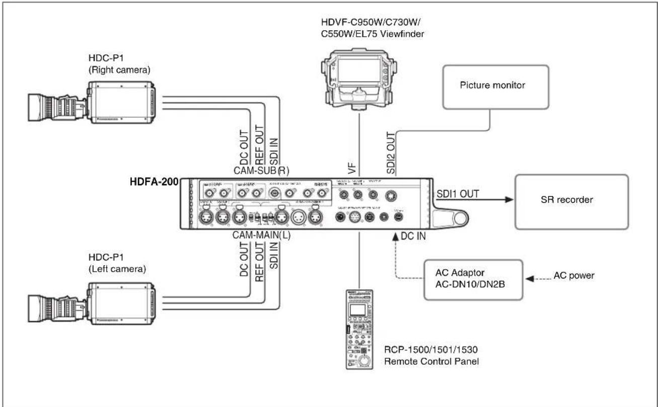
flowchart
graph TD
    A["HDFA-200 Camera"] -->|DC OUT REF OUT SDI IN| B["HDVF-C950W/C730W/C550W/EL75 Viewfinder"]
    A -->|DC OUT REF OUT SDI IN| C["HDCA-P1 (Left camera)"]
    A -->|DC OUT REF OUT SDI IN| D["HDCA-P1 (Right camera)"]
    A -->|AC Adaptor AC-DN10/DN2B| E["RS recorder"]
    A -->|AC power| F["Remote Control Panel"]
    A -->|VDV| G["Picture monitor"]
    A -->|VDI2OUT| H["DSI1 OUT"]
    A -->|DC IN| I["DC MAIN(L)"]
    style A fill:#f9f,stroke:#333
    style B fill:#ccf,stroke:#333
    style C fill:#ccf,stroke:#333
    style D fill:#ccf,stroke:#333
    style E fill:#ccf,stroke:#333
    style F fill:#ccf,stroke:#333
    style G fill:#ccf,stroke:#333
    style H fill:#ccf,stroke:#333
    style I fill:#ccf,stroke:#333
System operation example (two cameras with a Camera Control Unit)
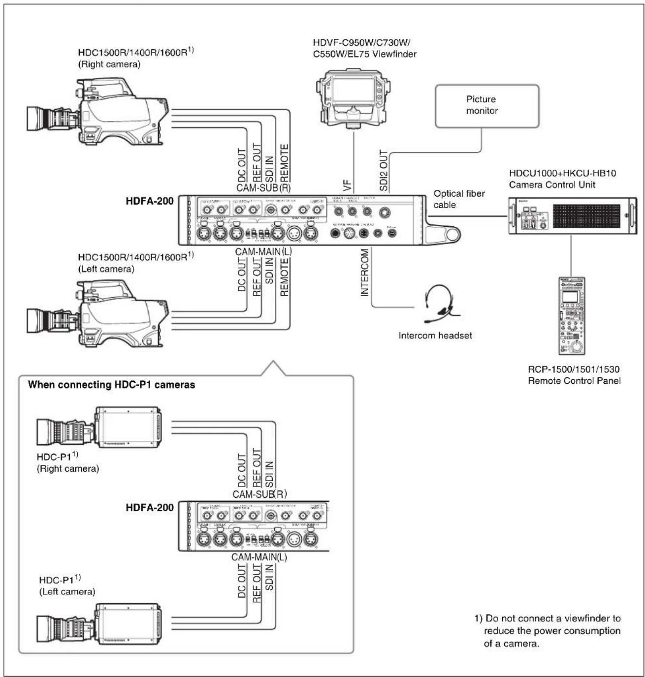
flowchart
graph TD
    A["HDCA1500R/1400R/1600R¹"] -->|Right camera| B["HDFA-200"]
    C["HDVF-C950W/C730W/C550W/EL75 Viewfinder"] -->|V/f| D["HDCA1500R/1400R/1600R¹"]
    E["Picture monitor"] --> F["HDCA1500R/1400R/1600R¹"]
    B --> G["Cam-SUB(R)"]
    B --> H["SDIIN REMOTE"]
    B --> I["DC OUT REF OUT SDI IN REMOTE"]
    B --> J["INTERCOM"]
    B --> K["Optical fiber cable"]
    L["Intercom headset"] --> M["HDCU1000+HKCU-HB10 Camera Control Unit"]
    M --> N["RCP-1500/1501/1530 Remote Control Panel"]
    O["When connecting HDC-P1 cameras"] --> P["HDC-P1¹"] --> Q["Right camera"]
    R["HDFA-200"] --> S["DC OUT REF OUT SDI IN"]
    R --> T["DC OUT REF OUT SDI IN"]
    R --> U["DC OUT REF OUT SDI IN"]
    V["HDFA-200"] --> W["DC OUT REF OUT SDI IN"]
    V --> X["DC OUT REF OUT SDI IN"]
    Y["HDFA-200"] --> Z["DC OUT REF OUT SDI IN"]
    style A fill:#f9f,stroke:#333
    style C fill:#f9f,stroke:#333
    style E fill:#f9f,stroke:#333
    style L fill:#f9f,stroke:#333
    style R fill:#f9f,stroke:#333
    style V fill:#f9f,stroke:#333
    style Q fill:#ccf,stroke:#333
    style S fill:#ccf,stroke:#333
    style T fill:#ccf,stroke:#333
    style U fill:#ccf,stroke:#333
    style V fill:#ccf,stroke:#333
    style W fill:#ccf,stroke:#333
    style X fill:#ccf,stroke:#333
    style Y fill:#ccf,stroke:#333
    style Z fill:#ccf,stroke:#333
System operation example with a Digital Cinematography Camera F35
An F35 with a Camera Control Unit
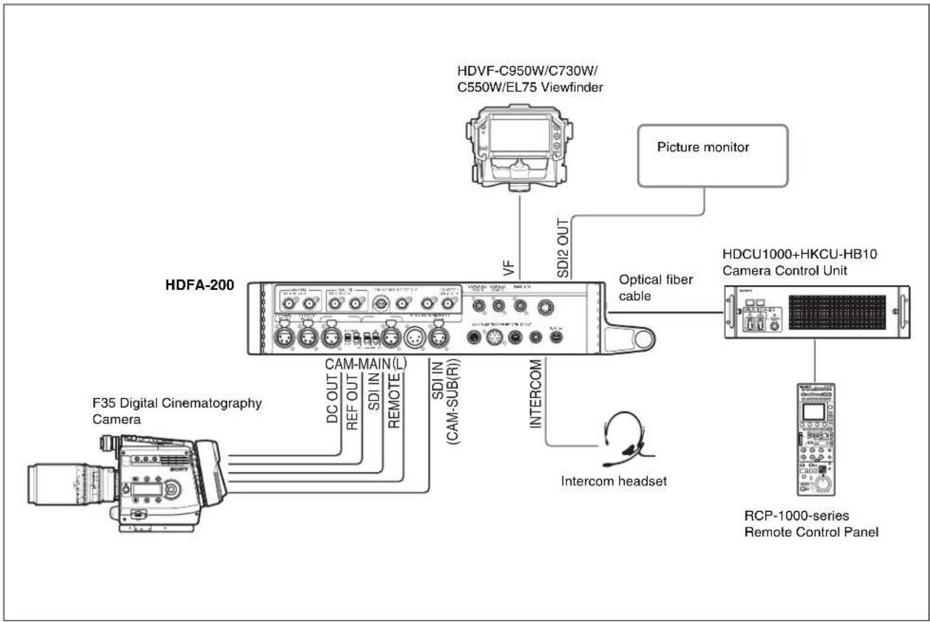
Parts Identification
Front panel
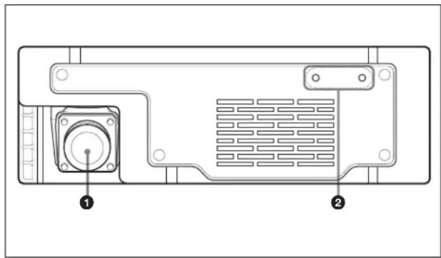
natural_image
Technical diagram of a computer rear panel showing internal components and labeled parts (no text or symbols beyond labels)①Camera Control Unit (CCU) connector (optical fiber connector)
Connect an HDCU1000 Camera Control Unit with an HKCU-HB10 3G Fiber Transmission Unit mounted or HDCU1500 with an HKCU-HB15 mounted, using an optical fiber cable.
A single optical fiber cable enables transmission of power, control signals, video signals, and audio signals between two cameras and an HDCU1000/1500.
②Cable clamp belt attachment screw holes
Attach the cable clamp belt (supplied) to secure the optical fiber cable.
Rear panel
SY type: Models for JN and SY
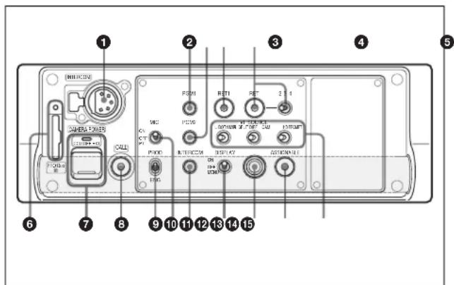
①INTERCOM connector (XLR 5-pin)
Connect an XLR 5-pin headset for input and output of intercom audio signals.
The connector can be used for communication over the engineer line when the camera is in standby status.
②PGM1 (Program 1) knob
To adjust the audio listening level of program 1.
③PGM2 (Program 2) knob
To adjust the audio listening level of program 2.
④RET 1 (return video 1) button
The return video 1 signal is displayed on the viewfinder screen while the button is held pressed.
⑤ RET (return video) button and 2/3/4 (return video 2/3/4) select switch
When other return video systems are used in addition to return video 1, the signal selected with the 2/3/4 select switch is displayed on the viewfinder screen while holding the RET button pressed.
Note
The RET 1 button has priority over the RET (2/3/4) button if both buttons are pressed.
⑥ "Memory Stick Duo" slot and access lamp
When you insert a "Memory Stick" into the slot, the access lamp lights in green.
The lamp is lit in red while writing/reading data to/from the "Memory Stick."
Notes
- Only a "Memory Stick" of Duo size can be used with the camera.
- When the access lamp is lit in red, do not insert/remove the "Memory Stick Duo" or turn off the camera.
For details on "Memory Stick", see "Using a "Memory Stick" (page 35).
⑦CAMERA POWER switch and indicator
CCU: To operate on power supply via the connected CCU.
OFF: Not to supply power.
EXT: To operate on power supply through the DC IN connector.
The indicator is lit in green during operation. It is lit in red while standby power is being supplied from the CCU, even if the switch is set to OFF.
Note
If the unit is connected to a CCU with the switch set to EXT for power being supplied through the DC IN connector, the CABLE ALARM (OPEN) indicator on the CCU may light, but the unit and CCU can be used.
⑧CALL button
Press to call the operator of the external control device (RCP, etc.). The call lamp of the connected device will light.
⑨Line select switch
To select the intercom line:
PROD: Producer line
ENG: Engineer line
⑩MIC (microphone) switch
Turns ON and OFF the microphone of the intercom headset.
ON: To turn on the microphone.
OFF: To turn off the microphone.
PTT: To turn on the microphone while the switch is set to this position. The switch is not locked at this position.
⑪ INTERCOM level control
To adjust the intercom audio listening level.
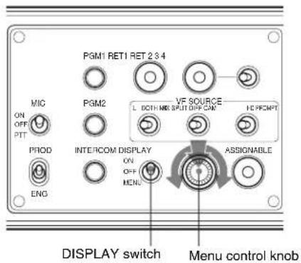
⑫DISPLAY switch
Select the display on the viewfinder screen.
ON: To display various textual information, such as messages showing the camera settings and operating status, in addition to camera images.
OFF: To display camera images only.
MENU: To display menus for settings, in addition to camera images.
⑬Menu control knob (rotary encoder)
Used to select settings from menus displayed on the viewfinder screen (by rotating it) and to confirm settings (by pushing it). Displayed items are depending on the setting of the DISPLAY switch.
When set to ON: The status screen is displayed when the knob is pressed.
When set to OFF: The VF SOURCE message is displayed when the knob is pressed. If the knob is pressed again while the message is displayed, the displayed items can be operated.
When set to MENU: The ordinal menu operation is available.
For details, see "Screen display of the viewfinder" (page 20).
⑭ASSIGNABLE button
You can assign a function by using ASSIGN REAR on the
15VF SOURCE switches
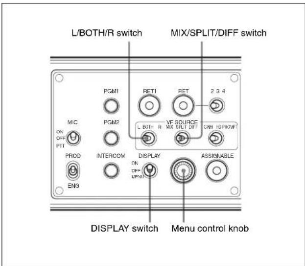
In 3D mode, these select the pictures to be displayed on the viewfinder screen.
L/BOTH/R switch
L: To display the main camera (left) picture.
BOTH: To display the pictures of both the main (left) and sub (right) cameras. The displayed style is selected with the MIX/SPLIT/DIFF switch.
R: To display the sub camera (right) picture.
MIX/SPLIT/DIFF switch
Select the display style for when the L/BOTH/R switch is set to BOTH. The settings for each screen are made on the VF SOURCE page of the OPERATION menu. The display style for each camera is set with the menu of the camera.
MIX: To display the mixed pictures from the main (left) and sub (right) cameras.
SPLIT: To display the pictures from the main (left) and sub (right) cameras on a split screen.
DIFF: To display difference between the pictures from the main (left) and sub (right) cameras.
CAM/HD PROMPT switch
Select a picture to be displayed on the viewfinder screen.
CAM: To display the picture from the cameras connected to the unit. The displayed picture is selected with the L/BOTH/R and MIX/SPLIT/DIFF switches.
HD PROMPT: To display the picture input to the HD PROMPTER connector on the CCU. If the output signal of an MPE-200 Multi Image Processor is input to the HD PROMPTER connector on the CCU, the picture processed with the MPE-200 can be monitored on the viewfinder screen.
CE type: Models for CE and E33
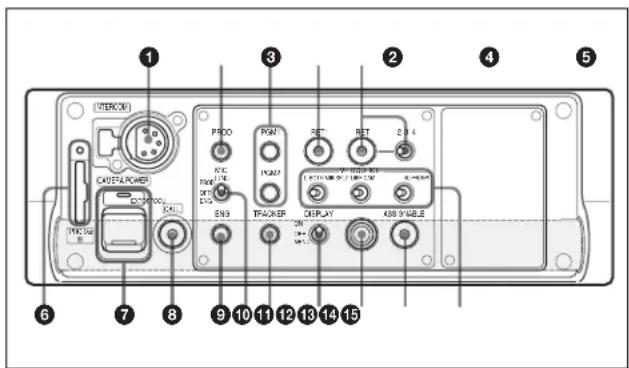
① and ④ to ⑧ and ⑫ to ⑮ are the same as those of the SY type.
②PROD (producer line) control
To adjust the intercom audio listening level of the producer line.
③PGM1 (program 1) and PGM2 (program 2) controls
To adjust the audio listening level of program 1 or program 2, respectively.
⑨ENG (engineer line) control
To adjust the intercom audio listening level of the engineer line.
⑩MIC LINE (intercom microphone line) switch
To select the talk line for intercom:
PROD: To talk over the producer line
OFF: To turn off the headset microphone for the intercom line
ENG: To talk over the engineer line
11TRACKER control
To adjust the intercom audio listening level at the TRACKER connector on the side panel.
Side panel
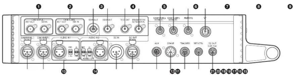
10
①CAM-MAIN(L) connectors (BNC type)
REF OUT: To supply an external gen-lock signal to the camera for synchronization. Connect to the GENLOCK IN connector on the main camera (left).
SDI IN: To input an HD-SDI signal of the camera. In 3D mode, connect to the SDI 1 connector of the main camera (left).
②CAM-SUB(R) connectors (BNC type)
REF OUT: To supply an external gen-lock signal to the camera for synchronization. Connect to the GENLOCK IN connector on the sub camera (right).
SDI IN: To input an HD-SDI signal of the camera. In 3D mode, connect to the SDI 1 connector of the sub camera (right).
③SDI1 OUT (serial digital interface) connector (BNC type)
For HD-SDI signal output.
The output signal is selected by menu operation. The selectable signal is different between 2D mode and 3D mode.
④SDI2 OUT (serial digital interface) connector (BNC type)
For HD-SDI or SD-SDI signal output.
The output signal is selected by menu operation. The selectable signal is different between 2D mode and 3D mode.
⑤TEST OUT connector (BNC type)
For an analog signal output.
This supplies a VBS signal, an HD signal equal to the signal output from the VF connector, an HD-SYNC signal, or an SD-SYNC signal, depending on which of these you have selected on the menu.
Note
The VBS output signal has no subcarrier phase-lock function with respect to external sync signals.
⑥PROMPTER1/GENLOCK IN (prompter 1 signal output/external sync signal input) connector (BNC type)
Set the switch according to the signal at the connector.
PROMPTER1: For output of the VBS prompter 1 signal (valid only when a camera control unit is connected). When a camera control unit having two prompter inputs is connected, the signal of input 1 is output from this connector.
GENLOCK IN: For input of an external gen-lock signal (BB or 3-level sync) when the camera is used as a standalone device.
Note
Even when a BB signal is used for the external sync signal, no subcarrier phase-lock function is available for the VBS output signal.
⑦CAM-MAIN(L) REMOTE connector (8-pin)
For transmitting the control signal with the camera. Connect this to the REMOTE connector of an HDC1500R/1600R/1400R/1500/1600 HD Color Camera or F35 Digital Cinematography Camera. In 3D mode, connect it to the main camera (left).
Note
When an HDC-P1 is used, do not connect this connector.
⑧ CAM-SUB(R) REMOTE connector (8-pin)
For transmitting the control signal with the camera. Connect this to the REMOTE connector of an HDC1500R/1600R/1400R/1500/1600 HD Color Camera. In 3D mode, connect it to the sub camera (right).
Note
When an HDC-P1 is used, do not connect this connector.
⑨REMOTE connector (8-pin)
For connection to an RCP-1000-series Remote Control Panel, or MSU-1000/1500 Master Setup Unit.
⑩VF (viewfinder) connector (20-pin)
Connect the cable of the viewfinder (not supplied).
①CAM-MAIN(L) DC OUT connector
To supply power to the camera (10.5 to 17 V DC, max 5.5 A ^1 ). In 3D mode, connect to the DC IN connector of a camera used as a main camera (left).
If an F35 Digital Cinematography Camera is connected, connect to the DC IN connector on the interface box.
1) The power capacity to be supplied is limited. For details see "Notes on Power Supplied from This Unit" (page 14).
⑫CAM-SUB(R) DC OUT connector
To supply power to the camera (10.5 to 17 V DC, 5.5 A ^1 max.). In 3D mode, connect to the DC IN connector of a camera used as a sub camera (right).
1) The power capacity to be supplied is limited. For details see "Notes on Power Supplied from This Unit" (page 14).
13 AUDIO IN 1 connector (XLR 3-pin) and select switches
Connect a channel 1 audio signal and set the switch according to the connected source device.
Audio input select switch
Set to the appropriate position according to the equipment connected to the AUDIO IN 1 connector.
MIC: When an external microphone is connected
LINE: When a line-level (0 dBu) signal source is connected
Microphone power switches
When a microphone is connected to the corresponding AUDIO IN 1 connector, set whether or not to supply a power to the microphone.
OFF: Not to supply a power
+48V: To supply a power of +48 V
(No function has been assigned to the uppermost position. No power is supplied to the microphone.)
Note
To supply a power of +12 V, consult your Sony representative.
14 AUDIO IN 2 connector (XLR 3-pin) and select switch
Connect a channel 2 audio signal and set the switch according to the connected source device.
Audio input select switch
Set to the appropriate position according to the equipment connected to the AUDIO IN 2 connector.
MIC: When an external microphone is connected
AES/EBU: When a digital audio signal is connected (The signal must be in synchronization with the camera output).
LINE: When a line-level (0 dBu) signal source is connected
Microphone power switches
When a microphone is connected to the corresponding AUDIO IN 2 connector, set whether or not to supply a power to the microphone.
OFF: Not to supply a power
+48V: To supply a power of +48 V
(No function has been assigned to the uppermost position. No power is supplied to the microphone.)
Note
To supply a power of +12 V, consult your Sony representative.
⑮DC IN (DC power supply input) connector (XLR 4-pin)
For connection to an AC-DN10 AC Adaptor, etc. to supply power (10.5 to 17 V DC) to the unit.
⑯DC OUT (DC power supply output) 4A max connector (4-pin)
To supply power to an external device such as a lens (10.5 to 17 V DC, max. 4 A ^2 ). The output current depends on the device to be used.
2) The power capacity to be supplied is limited. For details, see "Notes on Power Supplied from This Unit" (page 14).
⑰AUX connector (12-pin)
For the future use.
⑱CRANE connector (12-pin)
For external interface, such as viewfinder and trunk signal.
19 TRACKER connector (10-pin)
For communication a camera operator and tracker, and transmission of Intercom 1 and 2. An up tally signal and program audio signal are also output.
20RET CTRL (return control) connector (6-pin)
For connection to a CAC-6 Return Video Selector.
②DC OUT (DC power supply output) 0.5A max connector (4-pin)
To supply power to a script light of a BKP-7911 Script Holder (10.5 to 17 V DC, max. 0.5A ^3 ).
3) The power capacity to be supplied is limited. For details, see "Notes on Power Supplied from This Unit" (page 14).
Installation and Connections
Notes on Power Supplied from This Unit
Capacity of power current supplied from the DC OUT connectors on the HDFA-200 is limited.
Supplied power voltage (when power is supplied from a CCU): 14 V
• CAM MAIN(L) DC OUT connector: max 5.5 A
• CAM SUB(R) DC OUT connector: max 4 A
- DC OUT 4A max connector: max 4 A
- DC OUT 0.5 A max connector: max 0.5 A
- VF connector: power of up to 2 A can be supplied to a connected viewfinder
- AUX connector: power of up to 1 A can be supplied to a connected device
- TRACKER connector: power of up to 0.5 A can be supplied to a connected device
Notes
- The total amount of current from the above-mentioned connectors is 13 A in maximum. The maximum amount of the current is limited depending on the type of CCU and the length of the optical fiber cable used.
- The total amount of current from the CAM SUB(R) DC OUT connector and DC OUT 4A max connector is limited to 6.5 A.
Limit of power supply according to the cable length
The amount of the supplied current depends on the optical fiber cable length as shown below.
When connecting to an HDCU1000
Optical fiber cable length 1900 m (6232 ft.): max. 7 A
Optical fiber cable length 1600 m (5248 ft.): max. 9 A
Optical fiber cable length 1200 m (3936 ft.): max.12 A
Optical fiber cable length 1100 m (3608 ft.): max. 13 A
When connecting to an HDCU1500
Optical fiber cable length 1100 m (3608 ft.): max. 6 A
Optical fiber cable length 700 m (2296 ft.): max. 8 A
Optical fiber cable length 200 m (656 ft.): max. 9.2 A
Optical fiber cable length 50 m (164 ft.): max.10 A
Notes
- The above values are merely reference values (from measurements taken with use of FURUKAWA 9.2 -mm cable).
- If an HDFA-200 is operated with external DC power, the amount of current supplied to external devices is 8 A at maximum.
Mounting the Unit to a Tripod
The unit can be mounted on a tripod, using one of the tripod mounting holes on the bottom of the unit.
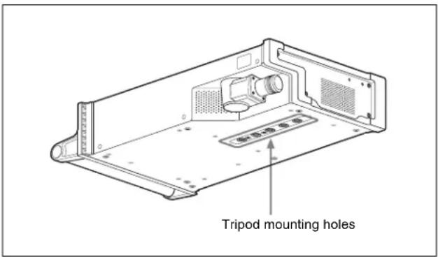
Caution
- Select an appropriate hole from among those at the bottom of the unit, considering the balance of the weight of the unit and the tripod. If an inappropriate hole is selected, the unit may fall over.
- Check that the size of the selected hole matches that of the screw of the tripod. If they do not match, the unit cannot be attached to the tripod securely.
Mounting on a Rig
The HDFA-200 can be mounted on a rig, using the holes on the bottom or top of the unit (see "Dimensions" (page 38)). Select appropriate holes according to the type and weight of the rig.
For details on mounting, consult a rig manufacturer.
Connecting Cameras
Connect cameras to the unit, and connect the unit and CCU, using an optical fiber cable.
Connecting an HDC-P1
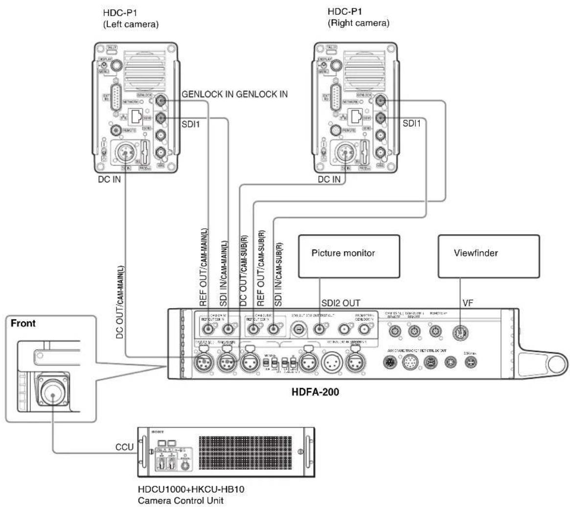
flowchart
graph TD
    A["Front"] --> B["HDFA-200"]
    B --> C["CCU"]
    C --> D["HDCU1000+HKCU-HB10<br>Camera Control Unit"]
    B --> E["HDCA1000+HKCU-HB10<br>Camera Control Unit"]
    B --> F["Viewfinder"]
    B --> G["Picture monitor"]
    B --> H["SDI2 OUT"]
    B --> I["SDI1"]
    B --> J["SDI1"]
    B --> K["SDI1"]
    B --> L["SDI1"]
    B --> M["SDI1"]
    B --> N["SDI1"]
    B --> O["SDI1"]
    B --> P["SDI1"]
    B --> Q["SDI1"]
    B --> R["SDI1"]
    B --> S["SDI1"]
    B --> T["SDI1"]
    B --> U["SDI1"]
    B --> V["SDI1"]
    B --> W["SDI1"]
    B --> X["SDI1"]
    B --> Y["SDI1"]
    B --> Z["SDI1"]
    B --> AA["SDI1"]
    B --> AB["SDI1"]
    B --> AC["SDI1"]
    B --> AD["SDI1"]
    B --> AE["SDI1"]
    B --> AF["SDI1"]
    B --> AG["SDI1"]
    B --> AH["SDI1"]
    B --> AI["SDI1"]
    B --> AJ["SDI1"]
    B --> AK["SDI1"]
    B --> AL["SDI1"]
    B --> AM["SDI1"]
    B --> AN["SDI1"]
    B --> AO["SDI1"]
    B --> AP["SDI1"]
    B --> AQ["SDI1"]
    B --> AR["SDI1"]
    B --> AS["SDI1"]
    B --> AT["SDI1"]
    B --> AU["SDI1"]
    B --> AV["SDI1"]
    B --> AW["SDI1"]
    B --> AX["SDI1"]
    B --> AY["SDI1"]
    B --> AZ["SDI1"]
    B --> BA["SDI1"]
    B --> BB["SDI1"]
    B --> BC["SDI1"]
    B --> BD["SDI1"]
    B --> BE["SDI1"]
    B --> BF["SDI1"]
    B --> BG["SDI1"]
    B --> BH["SDI1"]
    B --> BI["SDI1"]
    B --> BJ["SDI1"]
    B --> BK["SDI1"]
    B --> BL["SDI1"]
    B --> BM["SDI1"]
    B --> BN["SDI1"]
    B --> BO["SDI1"]
    B --> BP["SDI1"]
    B --> BQ["SDI1"]
    B --> BR["SDI1"]
    B --> BS["SDI1"]
    B --> BT["SDI1"]
    B --> BU["SDI1"]
    B --> BV["SDI1"]
Settings when connecting HDC-P1 cameras
When an HDFA-200 and HDC-P1 cameras are connected, a CCA-5 camera control signal cable cannot be connected. Communication between an HDFA-200 and HDC-P1 is made with the special sync (UNIVERSAL SYNC) and command signals overlaid on the HD-SDI signal. Check that 3D mode is set to ON on the RCP, MSU or CCU.
To set on an HDFA-200
Set REF OUT of CAM1 and CAM2 on the ADAPTER MODE (M05) page of the MAINTENANCE menu to UNIVERSAL. For the other settings, see "Preparatory Settings" (page 22).
To set on an HDC-P1
Set GENLOCK on the GENLOCK (M13) page of the MAINTENANCE menu to ENABLE. HV Phase adjustment value for GENLOCK is automatically invalid.
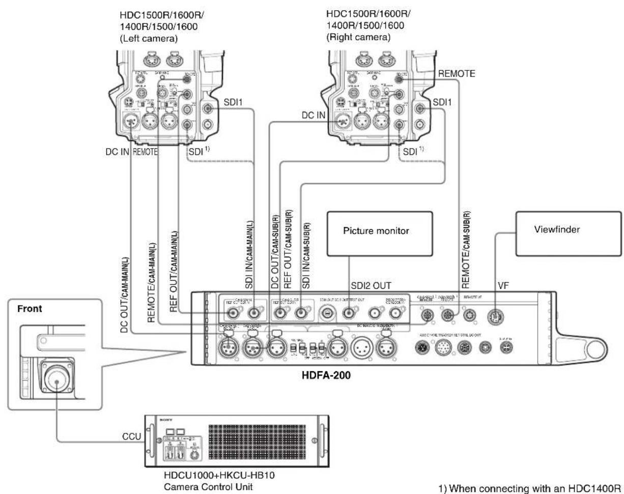
Settings when connecting HDC1500R-series cameras
Connect a CCA-5 camera control signal cable (hereafter referred to as CCA-5 cable) to control the camera from an HDFA-200. Be sure to make left and right camera connections correctly. The camera to which the CCA-5 cable for left side is connected is the main camera. In normal operation, the CCA-5 cable connection, left or right, cannot be distinguished. Display the Channel ID and check the left and right cameras. Check that 3D mode is set to ON on the RCP, MSU, or CCU.
To set on an HDFA-200
Set REF OUT of CAM1 and CAM2 on the ADAPTER MODE (M05) page of the MAINTENANCE menu to HD-SYNC.
For the other setting, see "Preparatory Settings" (page 22).
Note
Special SYNC (UNIVERSAL SYNC) cannot be used as a reference signal. Be sure to set to HD-SYNC.
To set on an HDC1500R-series camera
Set the GENLOCK IN/RET IN/PROMPTER switch on the rear panel to GENLOCK IN.
Connecting an F35
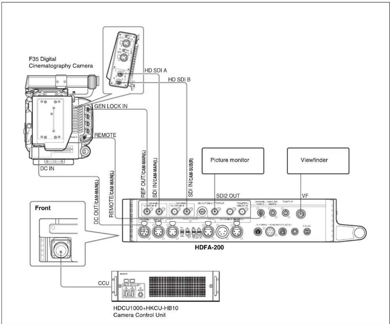
Settings when connecting an F35 (2D mode)
Set 3D mode to OFF on the RCP, MSU, or CCU.
To set on an MSU or RCP
Set on the Configuration screen as shown below.
1 Display the Configuration screen (Config screen for an RCP).
2 Select 3D System.
3 Select 3D Mode.
4 Set 3D mode to OFF.
To set on a CCU
Set 3D OPE to OFF on the 3D SETTINGS (S08) page of the SYSTEM OPERATION menu. Then set EVS/SHUTTER to OFF on the DISPLAY (C10) page of the CCU CONFIGURATION menu.
Connecting a Camera Control Unit (CCU)
Connecting the unit and a CCU
A camera control unit (CCU) to be connected to this unit requires that an HKCU-HB10/HB15 3G Fiber Transmission Unit be mounted. Connect the unit and CCU, following the procedures below.
1 Remove the cap from the fiber connector of this unit.
2 Connect the CCU connector on the unit and the CAMERA connector on a CCU, using an optical fiber cable.
3 Set the CAMERA POWER switch on the unit to CCU.
Once connection is made correctly and power is supplied to the unit, the CAMERA POWER indicator on the unit and the POWER indicator on the CCU light in green.
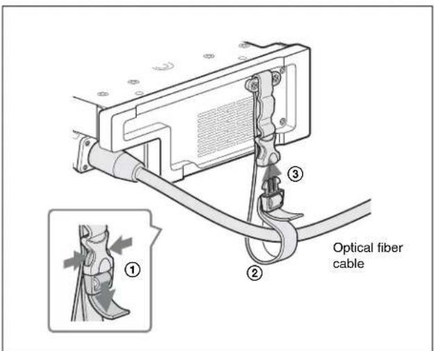
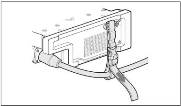
Using the cable clamp belt
When a cable clamp belt (supplied) to the unit, an optical fiber cable can be fastened to the front panel of the unit.
1 Insert the belt bracket into the upper loop of the cable clamp belt and secure the cable clamp belt to the camera, using the two supplied screws (+B3×8).
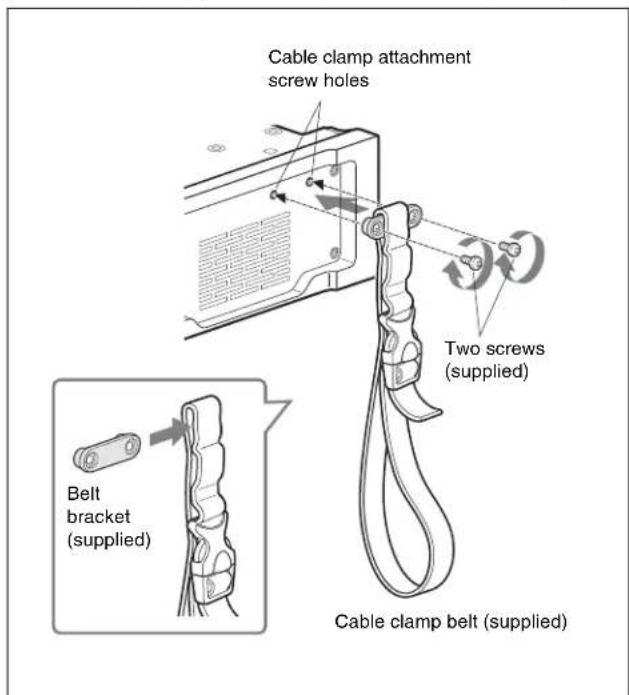
2 ① Release the buckle, ② bundle the cable with the belt, ③ then lock the buckle again.
3 Adjust the length by pulling down the end of the belt.
natural_image
Technical line drawing of a cable connector with attached cable and cable clamp (no text or symbols)Connecting a CCU in 3D mode
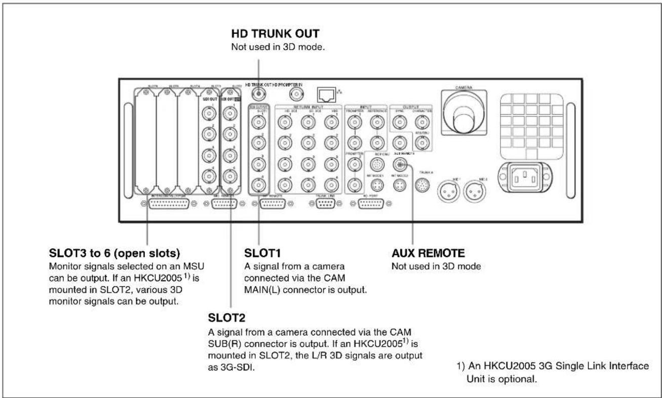
To connect an HDCU1000
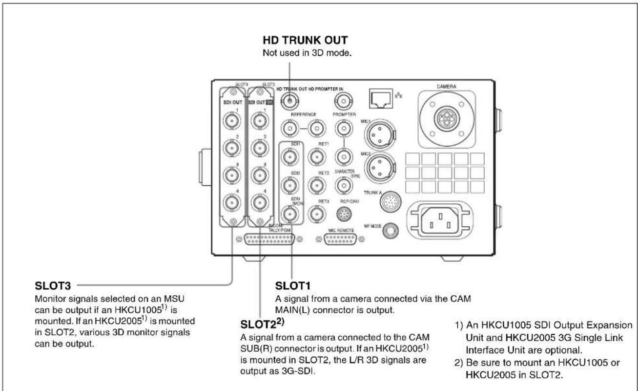
To connect an HDCU1500
Attaching a Viewfinder
Attaching a viewfinder to the unit
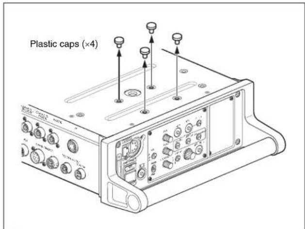
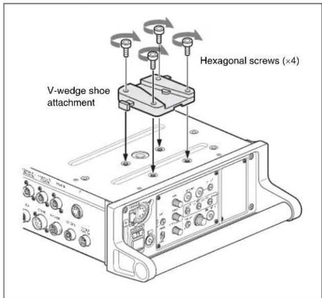
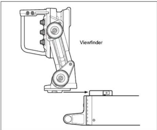
Attach the viewfinder using the viewfinder attaching holes on the top of the unit.
1 Remove the four plastic caps from the viewfinder attaching holes.
2 Attach the V-wedge shoe attachment (supplied with the viewfinder) to the unit using the hexagonal wrench (supplied with the viewfinder) and four hexagonal screws (4×12, supplied with the viewfinder).
Note
Never use the screws longer than 4×12.
3 Mount the viewfinder firmly in the V-wedge shoe attachment.
There is an audible click when the viewfinder snaps into the attachment.
Screen display of the viewfinder
Besides the video image, characters and messages showing the camera settings and operation status are displayed on the viewfinder screen.
Split screen, left and right camera picture inversion, or difference between the left and right camera pictures are available with settings on the VF SOURCE (03) page of the OPERATION menu. These functions can also be operated with the switches in the VF SOURCE block on the rear panel without using menu operation.
When the DISPLAY switch is set to ON
Items set to ON using the menu or related switches on the camera will be displayed.
Note
When an F35 is connected, set zoom position, focus position, and shutter/ECS not to be displayed.
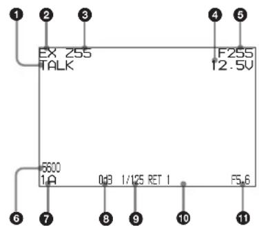
①TALK indication
Displayed when the intercom microphone is set to ON.
②EX (lens extender) indication
Displayed when a lens extender is in use.
③Zoom position indication
Indicates the approximate position of the zoom lens variator between wide angle (0) and telephoto (99).
④Battery voltage indication
When the CAMERA POWER switch is set to EXT, the DC IN voltage is displayed.
When the switch is set to CCU, the internal voltage of the camera is displayed.
⑤ Focus position indication
Shows the focus position of a zoom lens as a numeric value (0 to 255 [infinity]). (This is displayed only when a serial lens is used.)
65600K mode indication
Displayed when the internal electrical filter (5600K) is set to ON.
⑦Filter indication
Displays the types of filters currently selected. The number (1, 2, 3, 4, or 5) indicates the ND filter, and the letter (A, B, C, D, or E) indicates the CC filter.
⑧Gain value indication
Shows the video gain value (dB) set with the GAIN switch.
⑨Shutter/ECS indication
Displays the shutter/ECS status. Nothing is displayed if the electronic shutter is set to OFF.
10RET indication
Displayed when the RET 1 button or RET button (2/3/4) is pressed (RET1 to RET4).
⑪F-value indication
Indicates the lens F (iris opening) value.
When the menu control knob is pressed while the DISPLAY switch is set to ON, the status display is changed to show the following items:
① Assignable button indication
![②Format indication *1080-59.94i [4:2:2] *ASSIGNABLE REAR:OFF !5600K :ON OPT LV CAM:□□ ▼ ▼ ▼ ▼ ▼ ▼ CCU:□□ ▼ ▼ ▼ ▼ ▼ ▼ ④Light-receiving level indications ③‘!’ indication area](/content/2026/05/1083639/images/8cb6c5daa3950c48c0e4cdd5a996913b16eb41939d5072112d6a33d69ee9ad54.jpg)
① Assignable button indication
The function assigned to the ASSIGNABLE button (page 11) is indicated.
For the functions that can be assigned, see OPERATION menu
②Format indication
The current video format is displayed.
③‘!’ indication area
This area is used to display abnormal statuses, using the <^! IND> function. Display options can be set, using the menu.
For details, see OPERATION menu <'!' IND> (page 29).
④Light-receiving level indications
This area shows the light-receiving levels in segments.
CAM: Light-receiving level at the CCU connector of the unit CCU: Light-receiving level at the CAMERA connector of the CCU
Note
If a camera and camera control unit other than specified in "Compatible Devices" (page 5) is connected, correct indications may not be obtained.
When the DISPLAY switch is set to OFF
When the menu control knob is pressed with the L/BOTH/R switch set to L or R, the information regarding the camera currently displayed on the viewfinder screen ("CAM-L" or "CAM-R") appears.
The camera information will disappear after about three seconds with no operation.
To turn the display off, set MESSAGE to OFF on the VF SOURCE page of the OPERATION menu.
When the menu control knob is pressed with the L/BOTH/R switch is set to BOTH, the settings on the VF SOURCE page of the currently selected OPERATION menu are displayed on the viewfinder screen.
Settings on the VF SOURCE page of the OPERATION menu can be changed with the switches without the menu operation.
1 Press the menu control knob.
The pointer ( ) starts flashing, and the settings on the VF SOURCE page can be changed.
The information will disappear after about three seconds with no operation.
2 The items shown below can be changed with the MIX/SPLIT/DIFF switch.
MIX: MIX mode settings
SPLIT: SPLIT mode settings (except for SIDE BY SIDE, TOP AND BOTTOM)
DIFF: Turning ON/OFF of CAM-CHROMA
Preparatory Settings
Setting the 3D Mode
To use an HDFA-200 in 3D mode, the 3D mode setting must be made.
When a Camera Control Unit is connected
Set 3D mode to ON on the Remote Control Panel (RCP), Master Setup Unit (MSU) or CCU. The HDFA-200 connected to the CCU operates in the mode set here.
To make setting on an MSU or RCP
Set it on the Configuration screen, as described below.
1 Display the Configuration screen (Config screen for an RCP).
2 Select 3D System.
3 Select 3D Mode.
4 Set 3D Mode to ON.
To display the 3D support menu on an MSU or RCP Set it on the Configuration screen, as described below.
1 Display the Configuration screen (Config screen for an RCP).
2 Select MSU (RCP for an RCP).
3 Select Security.
4 Set Engineer Mode to ON.
5 Select Item Permission.
6 Set 3D Menu Enable to ON.
To set it on a CCU
Set 3D MODE to ON on the 3D SETTINGS (S08) page of the SYSTEM OPERATION menu.
When an HDFA-200 is used as a standalone device
Set 3D MODE to ON on the ADAPTER MODE (M05) page of the MAINTENANCE menu of the HDFA-200.
Setting the Output Format
When a Camera Control Unit is connected
The output format is defined with the CCU. The settings on an HDFA-200 or camera are invalid.
For settings regarding the format, refer to the operation manual supplied with the CCU.
When an HDFA-200 is used as a standalone device
The output format is set with an HDFA-200.
Set the format on the OUTPUT FORMAT (M06) page of the MAINTENANCE menu.
The format for the cameras connected to the HDFA-200 is automatically set to the settings on the HDFA-200. However, for a camera such as an F35 that does not support the camera format command, set the format to the same one as for the HDFA-200, using the menu of the camera.
Setting the Picture Inverting Function for a Rig
In 3D mode, pictures from the left and right cameras can be inverted vertically or horizontally to suit the 3D rig to which cameras are mounted. For a camera without the picture inverting function, pictures are inverted with the circuit in the HDFA-200. For a camera that has the picture inverting function such as an HDC-P1, the camera's inverting function is controlled with commands. When inverting pictures, delay of the left and right camera's signals is automatically adjusted to match the timing.
Select an appropriate number from 1 to 12 for RIG on the IMAGE INVERTER (M10) page of the MAINTENANCE menu while monitoring pictures on the viewfinder screen.
For details, see
Menus
The menus displayed on the viewfinder screen enable various settings of the camera.
The following controls are used to operate the menus.
To enter Menu mode, you can use the DISPLAY switch on the rear panel.
Rotate the menu control knob to select menu items or values and push on it to register (enter) the selection.
Rear panel
Displaying Menu Pages
Displaying a menu page
Set the DISPLAY switch to MENU.
The menu page last accessed will be displayed. If it is the first time, the CONTENTS page of the USER menu will be displayed.
Displaying the TOP MENU screen
If you set the DISPLAY switch to MENU while holding the menu control knob pressed, "TOP" is displayed at the upper right corner of the screen.
Turn the menu control knob to move the pointer (→) on the display to "TOP" and push on the knob. The TOP MENU screen is displayed, listing the available menus.
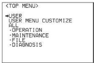
| Menu Purpose | |
| USER This menu can include menu pages selected from among the OPERATION, MAINTENANCE, FILE, and DIAGNOSIS menus, for convenience. Changing, adding, and deleting pages can be performed with the USER MENU CUSTOMIZE menu. | |
| USER MENU CUSTOMIZE | This menu allows you to edit the USER menu. For details on the USER menu, see “Editing the USER Menu” (page 25). |
| ALL This menu permits you to control all items of the OPERATION menu, MAINTENANCE menu, FILE menu, and DIAGNOSIS menu as a single menu. | |
| OPERATION | This menu contains items for camera operators to operate the camera. It mainly permits viewfinder, intercom, and switch settings. |
| MAINTENANCE | This menu contains items for performing camera maintenance operations, such as changing the system or setting infrequently. |
| FILE | This menu is for performing file operations, such as writing or clearing the reference file. |
| DIAGNOSIS | This menu enables you to confirm the self-diagnostic information. |
Setting the Menu
Selecting a menu on the TOP MENU screen
Rotate the menu control knob to align the pointer with the desired menu indication then push on the knob. The CONTENTS page (page No. 00) or the last accessed page of the selected menu is displayed.
Selecting a page from a CONTENTS page
Rotate the menu control knob to align the pointer with the desired page indication then push on the menu control knob.
If the screen can be scrolled, arrows will indicate the direction for scrolling.
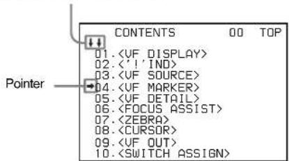
The selected page is displayed.
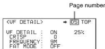
Changing the displayed page
1 Check that the pointer is located at the left of the page number then push on the menu control knob.
The pointer changes to a flashing question mark.
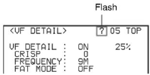
2 Rotate the menu control knob to flip through the pages, and push on the knob when the desired page is displayed.
The question mark will change back to the pointer, and operations with the displayed page are enabled.
To return to the TOP MENU screen
Align the pointer with "TOP" at the top right of the menu page, then push on the menu control knob.
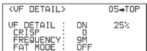
Setting the Menu Items
If a question mark is flashing at the left of the page number, push on the menu control knob to change it to the pointer. Operation on the displayed page is enabled.
1 Align the pointer with the desired item, then push on the menu control knob.
The pointer will change to a flashing question mark.
2 Rotate the menu control knob to change the setting value.
When the knob is rotated quickly, the values will change quickly; when rotated slowly, the values will change slowly.
To interrupt settings
Set the DISPLAY switch to OFF to turn off the menu screen display.
The setting operation can be restarted by setting the DISPLAY switch back to MENU.
3 Push on the menu control knob.
The question mark will change back to the pointer, and the new setting will be registered.
4 To change other setting items on the same menu page, repeat steps 1 through 3.
Specifying a character string
When you press the menu control knob with the pointer pointing to an item for which a character string, such as a file ID, is to be specified, a cursor and the list of selectable characters are displayed.
The displayed cursor can be moved by rotating the menu control knob.
1 Set the cursor to the position where you wish enter a character, then push on the menu control knob.
Another cursor appears on the character list.
2 Set the cursor to the character to be entered and push on the menu control knob.
Repeat steps 1 and 2.
- By selecting INS on the line below the character list, you can enter a space at the cursor position.
- Selecting DEL deletes the character at the cursor position.
- You can return to step 1 without changing the character by selecting RET.
- If you enter the permitted maximum number of characters (up to the stop mark at the right end of the line), the cursor moves to ESC on the line below the character list.
3 Select END and push on the menu control knob.
The new string you have set is registered.
To restore the previous string, select ESC and push on the menu control knob.
Returning a menu item to its standard value
Select the menu item to be returned to its standard value then hold the menu control knob pressed for three seconds while the pointer ( ) is displayed.
If "10 SEC CLEAR" has been set to ON on the
Ending menu operations
Set the DISPLAY switch to OFF.
Editing the USER Menu
You can select desired pages and items from the OPERATION, MAINTENANCE, FILE, and DIAGNOSIS menus and register them to the USER menu.
If you specify pages or items frequently used for the USER menu, you can easily call and use them.
The following pages are included on the factory-set USER menu:
| Menu page title USER menu No. | Source menu / page No. | |
| U01 OPERATION 09 | ||
| U02 OPERATION 03 | ||
| U03 OPERATION 05 | ||
| U04 OPERATION 06 | ||
| U05 OPERATION 01 | ||
| <‘! IND> | U06 OPERATION 02 | |
| U07 OPERATION 04 | ||
| U08 OPERATION 08 | ||
| U09 OPERATION 07 | ||
| U10 MAINTENANCE M11 | ||
| U11 OPERATION 11 | ||
| Menu page title | USER menu No. | Source menu / page No. |
| U12 OPERATION | 12 | |
| U13 MAINTENANCE M03 | ||
| U14 MAINTENANCE | M05 | |
| U15 MAINTENANCE | M06 | |
| U16 MAINTENANCE M08 | ||
| U17 MAINTENANCE M09 | ||
| U18 MAINTENANCE M07 | ||
| U19 MAINTENANCE M10 | ||
| U20 DIAGNOSIS D05 | ||
For the items on each page, see "OPERATION Menu" (page 28), "MAINTENANCE Menu" (page 31), or "DIAGNOSIS Menu" (page 34).
The USER MENU CUSTOMIZE menu allows you to configure the USER menu as follows:
- Creating a new page with items selected from multiple menu pages
- Adding (registering) a menu page (new page you create or existing menu page) to the USER menu
- Deleting (unregistering) a page from the USER menu
- Changing the order of pages of the USER menu
Editing by items
While the EDIT page contains factory-preset items, the USER 1 EDIT to USER 19 EDIT pages are all blank in their initial state. You can register up to 10 items, including blank lines, on each of these pages.
To add items to a page
1 Select USER MENU CUSTOMIZE on the TOP MENU screen (page 24).
If this is the first time the USER MENU CUSTOMIZE menu has been displayed, the CONTENTS page of the menu appears.
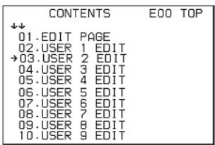
If the USER MENU CUSTOMIZE menu has been used before, the page last accessed appears.
2 If the CONTENTS page is displayed, turn the menu control knob to move the pointer to any of USER 1 EDIT to USER 19 EDIT then push on the menu control knob to display the page.
If a different page is displayed, turn the menu control knob until the desired page appears then push on the menu control knob to select the page.
Example: When you select the USER 2 EDIT page
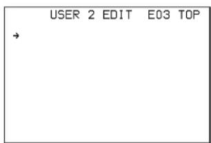
3 Move the pointer to the item to be added (this operation is unnecessary if no item exists on the page, as shown in the figure for the previous step) then push on the menu control knob. The EDIT FUNCTION screen appears.
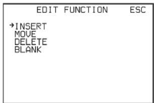
4 Move the pointer to INSERT and push on the menu control knob.
The page with the last item added appears.
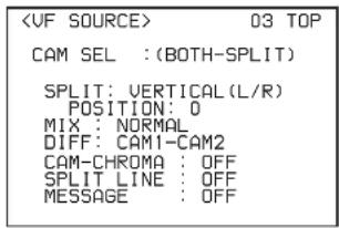
5 Add the items.
①Turn the menu control knob until the page that has the desired items appears, then push on the menu control knob.
②Turn the menu control knob to move the pointer to the desired item, then push on the menu control knob
The USER 2 EDIT page appears again, displaying the newly added item.
6 Add the remaining items by repeating steps 3 to 5.
You can add up to 10 items on one page.
To change the order of items on a page
1 Move the pointer to the item to be moved then push on the menu control knob.
The EDIT FUNCTION screen appears.
2 Select MOVE then push on the menu control knob.
The previously displayed page appears again.
3 Move the pointer to the position where you wish to move the item then push on the menu control knob.
| ITEM MOVE | ESC | |
| ↓↓ | ||
| →UF OUT | : COLOR | |
| UF DETAIL | : OFF | |
| MARKER | : ON | |
| CURSOR | : OFF | |
| ZEBRA SW | : OFF | |
| : 1 | ||
| ●ASSIGNABLE | : OFF | |
The item selected in step 1 moves to the position that you selected in step 3.
In the above example, ASSIGNABLE is moved to the top, and the other items are moved down one line.
Deleting items from a page
1 Move the pointer to the item to be deleted then push on the menu control knob.
The EDIT FUNCTION screen appears.
2 Select DELETE and push on the menu control knob. The previously displayed page appears again, and the message "DELETE OK? YES→NO" appears.
3 To delete, turn the menu control knob to move the pointer to YES and push on the menu control knob.
Inserting a blank line
1 Move the pointer to the item above which you wish to insert a blank line.
The EDIT FUNCTION screen appears.
2 Select BLANK then push on the menu control knob. The previously displayed page appears again, and a blank line is inserted above the specified item.
Note
You cannot insert a blank line on a page where 10 items have already been registered.
Editing by pages
You can add a page to the USER menu, delete a page from the USER menu, or replace pages, using the EDIT PAGE of the USER MENU CUSTOMIZE menu.
Adding a page
1 Select USER MENU CUSTOMIZE on the TOP MENU screen.
If this is the first time the USER MENU CUSTOMIZE menu has been displayed, the CONTENTS page of the menu appears. If the menu has been used before, the page last accessed appears.
2 If the CONTENTS page is displayed, turn the menu control knob to move the pointer to EDIT PAGE then push on the menu control knob to display the EDIT PAGE screen.
If a different page is displayed, turn the menu control knob until the EDIT PAGE screen appears then push on the menu control knob to select the page.
| EDIT PAGE E01 TOP | |
| ↓↓ | |
| 01. | <UF OUT> |
| →02. | <UF DETAIL> |
| 03. | <FOCUS ASSIST> |
| 04. | <UF DISPLAY> |
| 05. | <‘!' IND> |
| 06. | <UF MARKER> |
| 07. | <CURSOR> |
| 08. | <ZEBRA> |
| 09. | <SWITCH ASSIGN> |
| 10. | <POWER SAVE> |
3 Move the pointer to the position where you wish to add the page then push on the menu control knob.
The EDIT FUNCTION screen appears.
4 Select INSERT then push on the menu control knob. The selection screen appears.
| CONTENTS | ESC | |
| ↓↓ | ||
| →01. | USER | 1 |
| 02. | USER | 2 |
| 03. | USER | 3 |
| 04. | USER | 4 |
| 05. | USER | 5 |
| 06. | USER | 6 |
| 07. | USER | 7 |
| 08. | USER | 8 |
| 09. | USER | 9 |
| 10. | USER | 10 |
5 Move the pointer to the desired page then push on the menu control knob.
This adds the number and name of the selected page above the item selected in step 3.
To cancel addition of a page
Before pushing the menu control knob in step 5, turn the menu control knob to move the pointer to ESC at the top right of the screen then push on the menu control knob. The EDIT PAGE screen appears again.
Deleting a page
1 On the EDIT PAGE screen of the USER MENU CUSTOMIZE menu, move the pointer to the page to be deleted and push on the menu control knob. The EDIT FUNCTION screen appears.
2 Select DELETE then push on the menu control knob. The previously displayed page appears again, and the message "DELETE OK? YES→NO" appears.
| ITEM DELETE ESC | |
| DELETE OK? YES→NO | |
| 01. | |
| 02. | |
| 03. | |
| ●04. | |
| 05. | |
| 06. | |
| 07. | |
| 08. | |
| 09. | |
| 10. | |
3 To delete, turn the menu control knob to move the pointer to YES then push on the menu control knob.
Changing the order of pages
1 Display the EDIT PAGE screen of the USER MENU CUSTOMIZE menu. Turn the menu control knob to move the pointer to the page that you wish to move then push on the menu control knob.
The EDIT FUNCTION screen appears.
2 Select MOVE then push on the menu control knob.
The EDIT PAGE screen appears again.
3 Move the pointer to the position where you wish to move the page then push on the menu control knob.
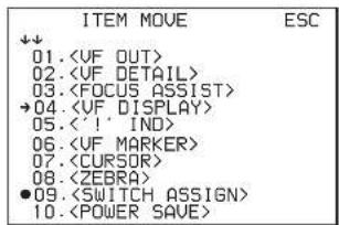
The page selected in step 1 is moved to the position selected in step 3.
In the above example,
OPERATION Menu
Note
These remarks are common for all the following menu tables. ON, OFF, 0, ... , in the Settings columns: Default settings
Page No. nn (Unn): For the pages that have been registered on the USER menu at the factory, the USER menu page numbers are indicated in parenthesis.
Execute by ENTER: Execute by pushing on the menu control knob.
| Page title Page No. | Item Settings | |
| EX ^1) | ON, OFF | |
| 01(U05) 1) Status of CAM L 2) Status of this unit | ZOOM ^1) | ON, OFF |
| DISP ^1) | LEFT, RIGHT | |
| FOCUS ^1) Valid only when a serial lens is used | ON, OFF | |
| ND ^1) | ON, OFF | |
| CC ^1) | ON, OFF | |
| 5600K ^1) | ON, OFF | |
| IRIS ^1) | ON, OFF | |
| GAIN ^1) | ON, OFF | |
| SHUTT ^1) | ON, OFF | |
| BATT ^2) | ON, OFF | |
| RETURN ^2) | ON, OFF | |
| TALK ^2) | ON, OFF | |
| MESSAG ^2) | ALL, AT, WRN, OFFALL: To display all messagesAT: To display Auto Setup information and higherWRN: To display warning messages and higher | |
| [IND]: Activate/deactivate the '!' indication (page 21). | ||
| [NORMAL]: Specify the conditions under which the '!' indication is not to be displayed even if [IND] is ON. (By specifying the standard or normal conditions here, nonstandard or abnormal conditions can be found with the '!' indication on the viewfinder.) | ||
| ND ^1) | [IND]ON, OFF | |
| [NORMAL] 1, 2, 3, 4 (combination allowed) | ||
| CC ^1) | [IND]ON, OFF | |
| [NORMAL] A, B, C, D (combination allowed) | ||
| 5600K ^1) | [IND]ON, OFF, - - - - - - - : with CCU connected | |
| [NORMAL] ON, OFF | ||
| SHUTT ^1) | [IND]ON, OFF, - - - - - - - : with CCU connected | |
| [NORMAL] ON, OFF | ||
| FAN ^2) | [IND]ON, OFF | |
| [NORMAL] AUTO1, AUTO2, MIN, MAX | ||
| EXT ^1) | [IND]ON, OFF | |
| FORMAT ^2) | [IND]ON, OFF | |
| [NORMAL] JN, SY model: 59.94i, 30PsF, 29.97PsF, 50i, 25PsF, 24PsF, 23.98PsF, 60P, 59.94P, 60i CE, E33 model: 59.94i, 30PsF, 29.97PsF, 50i 25PsF, 24PsF, 23.98PsF, 60P, 59.94P, 60i | ||
| CAM SEL (MAIN[L]), (SUB[R]), (BOTH-SPLIT), (BOTH-MIX), (BOTH-DIFF), (HD-PROMPT) | ||
| SPLIT HORIZONTAL(L/R), VERTICAL(L/R), VERTICAL(R/L), MIRROR, SIDE BY SIDE, TOP AND BOTTOM, -- | ||
| POSITION -99 to 99, 0 , -- | ||
| MIX NORMAL ,DUAL PICT, ANAGLYPH, LINE-ALTE1, LINE-ALTE2, DUALPICT, -- | ||
| DIFF CAM1-CAM2 , CAM2-CAM1, -- | ||
| CAM-CHROMA ON, OFF , -- | ||
| SPLIT LINE ON, OFF , -- | ||
| MESSAGE ON, OFF , -- | ||
| Page title Page No. | Item | Settings |
| MARKER ON, OFF | — | |
| WHITE, BLACK, DOT | ||
| CENTER | ON, OFF | |
| 1, 2, 3, 41: Entire cross2: Entire cross with a hole3: Center4: Center with a hole | ||
| SAFETY ZONE | ON, OFF | |
| 80.0, 90.0, 92.5, 95.0% | ||
| EFFECT | ON, OFF, (FOCUS)(FOCUS): Displayed when INDICATOR of(06) is ON. | |
| ASPECT | ON, OFF | |
| 16:9, 15:9, 14:9, 13:9, 4:3,(4.3)(4.3): If VF SCAN of(09) is set to 4:3 | ||
| MASK | ON, OFF, (ON)(ON): If VF SCAN of(09) is set to 4:3 | |
| 0 to 15 12Set the level to darken outside the aspect area. | ||
| SAFETYFor the safety marker in Aspect mode | ON, OFF, (AREA)(AREA): Displayed when AREA MARKER of(06) is ON. | |
| 80.0, 90.0, 92.5, 95.0% | ||
| VF DETAIL | ON, OFF | |
| 0 to 100%, 25% | ||
| CRISP | -99 to 99, 0 | |
| FREQUENCY | 9M, 14M, 18M | |
| FAT MODE ON, OFF | — | |
| FLICKER | ON, OFF | |
| AREA | 100%, 70%, 60%, 50%, 40% | |
| ZOOM LINK | 0%, 25%, 50%, 75%, 100% | |
| COLOR DETAIL ON, OFF | ||
| PEAK COLOR | ON, OFF | |
| CHROMA LEVEL | 100%, 50%, 25%, 0% | |
| INDICATOR ON, OFF, (EFFECT)(EFFECT): Displayed when EFFECT of(04) is ON. | ||
| MODE BOX | _, B&W, COL | |
| BOTTOM, LEFT, TOP, RIGHT | ||
| LEVEL 1 to 5, 3 | _ | |
| QUICK, SMOOTH | ||
| GAIN 0 to 99, 50 | _ | |
| OFFSET 0 to 99, 50 | _ | |
| AREA MARKER ON, OFF, (ASPECT)(ASPECT): Displayed when ASPECT SAFETY of(04) is ON. | ||
| SIZE SMALL, MIDDLE | _, LARGE | |
| POSITION LEFT, CENTER | _, RIGHT | |
| POSITION H 0 to 99, 50 | _ | |
| POSITION V 0 to 99, 50 | _ | |
| ZEBRA ON, OFF | _ | |
| 1, 2, 1&2 | ||
| ZEBRA1 LEVEL 50 to 109%, 70 | _ | |
| WIDTH 0 to 30%, 10 | _ | |
| ZEBRA2 50 to 109%, 100 | _ | |
| CURSOR | ON, OFF | |
| WHITE, BLACK, DOT | ||
| BOX/CROSS BOX_, CROSS | ||
| H POSITION 0 to 99, 50 | _ | |
| V POSITION | 0 to 99, 50 | |
| WIDTH 0 to 99, 50 | _ | |
| HEIGHT | 0 to 99, 50 | |
| VF OUT COLOR, Y, R, G, B. | ||
| RET MIX VF | ON, OFF | |
| MIX DIRECTION | MAIN, RET | |
| MIX VF MODE | Y-MIX, WIRE(W), WIRE(B) | |
| MIX VF LEVEL | 0 to 80% | |
| VF SCAN 16:9 | _, 4:3 | |
| ASSIGN REAR | JN, SY model:OFF, RETURN1 SW, RETURN2 SW, INCOM, VF DETAIL, MIX VF, 5600K, FAN MAX, VF SCAN, CURSOR, MARKER CE, E33 model:OFF, RETURN1 SW, RETURN2 SW, ENG, PROD, VF DETAIL, MIX VF, 5600K, FAN MAX, VF SCAN, CURSOR, MARKER | |
| Page title Page No. | Item | Settings |
| INTERCOM MIC | DYNAMIC, CARBON, MANUAL | |
| LEVEL | -60,-40,-20 dB, (-60 dB) Settings in ( ): With DYNAMIC or CARBON (cannot be changed) | |
| -6, 0, 6 dB Input gain | ||
| POWER | ON, OFF, (ON), (OFF) Settings in ( ): With DYNAMIC or CARBON (cannot be changed) | |
| UNBAL | ON, OFF, (ON), (OFF) Settings in ( ): With CARBON (cannot be changed) | |
| SIDE TONE MU, 1 to 99, 50 | ||
| 12 (U12) | ||
| INTERCOM RECEIVE SELECT | SEPARATE, MIX | |
| 13 | INTERCOM JN, SY model only | ---, LEFT, RIGHT, BOTH |
| ENG CE, E33 model only | ---, LEFT, RIGHT, BOTH | |
| PROD CE, E33 model only | ---, LEFT, RIGHT, BOTH | |
| PGM1 | ---, LEFT, RIGHT, BOTH | |
| PGM2 | ---, LEFT, RIGHT, BOTH | |
| TRACKER | ---, LEFT, RIGHT, BOTH | |
| TRACKER RECEIVE SELECT | SEPARATE, MIX | |
| 14 | INTERCOM JN, SY model only | ---, LEFT, RIGHT, BOTH |
| TALK CE, E33 model only | ---, LEFT, RIGHT, BOTH | |
| ENG CE, E33 model only | ---, LEFT, RIGHT, BOTH | |
| PROD CE, E33 model only | ---, LEFT, RIGHT, BOTH | |
| PGM1 | ---, LEFT, RIGHT, BOTH | |
| PGM2 | ---, LEFT, RIGHT, BOTH | |
| READ (MS→CAM) | Execute by ENTER. | |
| 15 See FILE menu F01. | WRITE (CAM→MS) | Execute by ENTER. |
| PRESET | Execute by ENTER. | |
| FILE ID Max.14 characters | ||
| CAM CODE | Display only | |
| DATE | Display only | |
MAINTENANCE Menu
| Page title Page No. | Item Settings | |
| AUTO BLACK Execute by ENTER. | ||
| AUTO WHITE Execute by ENTER. | ||
| AUTO LEVEL Execute by ENTER. | ||
| AUTO BLACK SHADING | Execute by ENTER. | |
| TEST OFF ____, SAW, 3STEP, 10STEP | ||
| AUTO IRIS ON, OFF ____ | ||
WINDOW 1, 2, 3, 4, 5, 6Select the auto iris windows: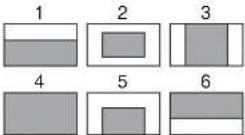 | ||
| MIC1 20 dB, 30 dB, 40 dB, 50 dB,60 dB, (20 dB), (30 dB), (40 dB), (50 dB), (60 dB) | ||
| MIC2 20 dB, 30 dB, 40 dB, 50 dB,60 dB, (20 dB), (30 dB), (40 dB), (50 dB), (60 dB) | ||
| MIC POWER | ||
| MIC1 (OFF), (48V), (AB), (- - ) | ||
| MIC2 (OFF), (48V), (AB), (- - ) | ||
| CALL SETTING | ||
| CCU CALL ---, ON ____, OFF | ||
| ADAPTER ---, OFF ON CALL | ||
| RELAY SETTING | ||
| CCU→CAM ---, OFF____, OM | ||
| ADAPTER→---, ON, OFF CAM | ||
| 3D MODE ON ____, OFF | ||
| CAM1 | ||
| REF OUT | HD-SYNC, UNIVERSAL | |
| COMMAND | (ENABLE), (- - ) | |
| CAM2 | ||
| REF OUT | HD-SYNC, UNIVERSAL, (- - ) | |
| COMMAND | (ENABLE), (- - ) | |
| Page title Page No. | Item | Settings |
| CURRENT | Displays the current format. | |
| ACTIVE LINE Not displayed when a CCU connected | JN, SY model:1080 59.94i, 1080 50i,1080 29.97PsF,1080 25PsF,1080 23.98PsF,1080 24PsF,720 59.94P, 720 50PCE, E33 model:1080 59.94i, 1080 50i,1080 29.97PsF,1080 25PsF,1080 23.98PsF,1080 24PsF,720 59.94P, 720 50P(Changed to the usable format according to the connected camera) | |
| (in 3D mode) | ||
| OUTPUT SIGNAL | L/R, VF, RET, SUB(R)L/R: RET button operation disabledVF: RET button operation enabled | |
| (in 2D mode) | ||
| OUTPUT SIGNAL | MAIN(L), VF, RET, SUB(R)MAIN(L): RET button operation disabledVF: RET button operation enabled | |
| ASPECT | SQ, EC | |
| OUTPUT | VBS, VF, HD-SYNC, SD-SYNC, PROMPTER | |
| (PWR SAVE) | Displayed in POWER SAVE mode only | |
| VBS-OUT | ||
| CHARACTER | ON, OFF | |
| GAIN | -127 to 127, 0 | |
| CHROMA | -127 to 127, 0 | |
| SETUP | ON, OFF | |
| HD SYNC-OUT | ||
| V-PHASE | -127 to 127, 0 | |
| H-PHASE | -127 to 127, 0 | |
| Page titlePage No. | Item Settings | |
| (in 3D mode) | ||
| M09 (U17) | SDI-1 OUT MAIN(L)____, HD PROMPTER,3G-SDI | |
| SDI-2 OUT VF-SOURCE, VF,SUB(R)____,RET, SD-SDIOutput an SD signal seton OUTPUT SIGNAL ofwhen SD-SDI selected | ||
| (in 2D mode) | ||
| SDI-1 OUT MAIN(L), HD PROMPTER,3G-SDI | ||
| SDI-2 OUT MAIN(L), VF, SUB(R), RET,SD-SDIOutput an SD signal seton OUTPUT SIGNAL ofwhen SD-SDI selected | ||
| (in 3D/2D mode) | ||
| (PWR SAVE) Displayed in POWER SAVEmode only | ||
| CHARACTER ON,OFF____Not displayed if SDI2 OUTis set to SUB(R) | ||
| EMB AUDIO ON,OFF____ | ||
| (1-MIC12-MIC2)(3-AES14-AES2) | Displayed when OUTPUT isMAIN(L) | |
| (1-PGM12-PGM2)(3-ENG4-PROD) | Displayed when OUTPUT isother than MAIN(L) | |
| Page titlePage No. | Item Settings | |
| (in 3D mode) | ||
| RIG: 1: L:NRML R:NRML | ||
| 1: L:NORMAL R:NORMAL | ||
| 2: L:H-Invert R:NORMAL | ||
| 3: L:V-Invert R:NORMAL | ||
| 4: L:HV-Invert R:NORMAL | ||
| 5: L:NORMAL R:H-Invert | ||
| 6: L:NORMAL R:V-Invert | ||
| 7: L:NORMAL R:HV-Invert | ||
| 8: L:HV-Invert R:HV-Invert | ||
| 9: L:H-Invert R:HV-Invert | ||
| 10: L:V-Invert R:HV-Invert | ||
| 11: L:HV-Invert R:H-Invert | ||
| 12: L:HV-Invert R:V-Invert | ||
| (in 2D mode) | ||
| H MIRROR (OFF), (ON) | ||
| V MIRROR (OFF), (ON) | ||
| (in 3D/2D mode) | ||
| V PHASE STATUS | ||
| CAM1 V (MATCH), (UNMATCH) | ||
| STATUS | ||
| CAM2 V (MATCH), (UNMATCH) | ||
| SDI-2 OUT | PWR SAVE,ACTIVE | |
| DOWN | PWR SAVE,ACTIVE | |
| CONVERTER | ||
| TRUNK | ON, OFF | |
| IF | 232C, 422A | |
| REFERENCE | Condition of synchronisation, display only | |
| GENLOCK | DISABLE, ENABLE | |
| STATUS | Display only | |
| FORMAT | ||
| PHASE | ||
| V | -1024 to 1023,0 | |
| HD H | -1700 to 1700,0 | |
| SD H | -1024 to 1023,0 | |
| DATE/TIME | yyyy/mm/ddhh:mm | |
| BEFORE END 11.5 V to 17.0 V | ||
| END 11.0 V to 11.5 V | ||
| FAN MODE OFF, AUTO1, AUTO2, MIN, MAXAUTO1: Normal rotationAUTO2: Slow rotation(The internal temperature may raise with the OFF setting.) | ||
| CAM BARS ON, OFF ____ | ||
| CAM MENU ON, OFF, (OFF)(OFF): When a camera other than an HDC-P1 is connected | ||
| DATE TYPE 1 Y/Mn/D, 2 Mn/D, 3 D/M/Y4 D/M, 5 M/D/Y, 6 M/DY: YearMn: Month (numeric)M: Month (character string)D: Day | ||
| FILTER WHT MEM ON, OFFSet to ON/OFF to use independent white memory at each CC filter position. | ||
| F NO. DISP CONTROL ____, RETURNSelect the iris indication on the panel when AUTO IRIS is off:CONTROL: To display the value from the cameraRETURN: To display the value returned from the lens(When AUTO IRIS is on, the value returned from the lens is always displayed.) | ||
FILE Menu
Three types of files can be used for easy adjustments of the camera; Operator, Scene, and Reference.
You can store the items set with the OPERATION menu and customized USER menu in the Operator file.
For the specific items included in these files, refer to the Maintenance Manual.
| Page title Page No. | Item Settings / Default | |
| READ (MS→CAM) Execute by ENTER.To read the operator file from a “Memory Stick” | ||
| F01 | WRITE (CAM→MS) Execute by ENTER.To write the current settings of the operator file items to a “Memory Stick” | |
| PRESET Execute by ENTER.To set the operator file items to the preset values in internal memory | ||
| STORE PRESET FILE | Execute by ENTER.To store the current settings of the operator file items in the operator file in internal memory. | |
| FILE ID Max.14 charactersEnter a comment for the operator file to be written to a “Memory Stick.”See “Specifying a character string” (page 25). | ||
| CAM CODE Camera code(display only) | ||
| DATE | Date(display only) | |
| 1 | To store and read scene files (paint data):When storing a file in camera memory, specify the number for STORE and execute by ENTER.When reading, only specify the number. | |
| F02 | 2 | |
| 3 | ||
| 4 | ||
| 5 | ||
| STORE | ||
| STANDARD Execute by ENTER.To read the standard paint data | ||
| STORE FILE | Execute by ENTER.To store the current settings of the reference file items in the reference file in internal memory. | |
| STANDARD Execute by ENTER.To read the standard values in the reference file in internal memory. | ||
| ALL PRESET | Execute by ENTER.To resume the factory-preset reference file | |
| Page title Page No. | Item | Settings / Default |
| PRESET OPERATOR | Execute by ENTER. | |
| 10 SEC CLEAR ON, OFF ____To activate/deactivate the function to clear the current menu item.See “Returning a menu item to its standard value” on page 25. | ||
| M.S. FORMAT Execute by ENTER.To initialize a “Memory Stick” | ||
DIAGNOSIS Menu
This menu is only for viewing and no setting is made using this menu.
| Page title Page No. | Item Indication | |
| CCU→CAM GREEN, YELLOW, RED, NG, NO SIGNAL | ||
| D01 | CAM→CCU GREEN, YELLOW, RED, NG, NO SIGNAL | |
| CAM1 OK RM, OK EMB, -- RM, -- EMBWhen CAM1 SYNC OUT of(M05) is set to HD SYNC, RM is displayed at the end, and when set to UNIVERSAL, EMB is displayed | ||
| D02 | ||
| CAM2 OK RM, OK EMB, -- RM, -- EMBWhen CAM2 SYNC OUT of(M05) is set to HD SYNC, RM is displayed at the end, and when set to UNIVERSAL, EMB is displayed | ||
| RM OK, -- | ||
| CCU OK, -- | ||
| SY OK, NG | ||
| D03 | SDI OK, NG | |
| DPR | OK, NG | |
| SY Vx.xx | ||
| D04 | SDI Vx.xx | |
| DPR | Vx.xx | |
| AT | Vx.xx | |
| D05 (U20) | ||
| MODEL | HDFA-200 | |
| D06 | NO | Serial No. |
Appendices
Notes on Use
Use and storage locations
Avoid using or storing the unit in the following places:
- Where it is subject to extremes of temperature
- In direct sunlight for extended period of time or close to heaters (Note that in summer the temperature in a car with the windows closed can reach 50^ (122°F)).
• Very damp or dusty places. - Where rain is likely to reach the unit.
- Places subject to severe vibration.
• Near strong magnetic fields. - Near transmitting stations generating strong radio waves.
Avoid violent impacts
Dropping the unit, or otherwise imparting a violent shock to it, is likely to cause it to malfunction.
Do not cover with cloth
While the unit is in operation, do not cover it with a cloth or other material. This can cause the temperature to rise, leading to a malfunction.
After use
Set the CAMERA POWER switch on the unit to the OFF position.
Care
If the body or panels of the unit become dirty, wipe them with a dry cloth. For severe dirt, use a soft cloth steeped in a small amount of neutral detergent, then wipe dry. Do not use volatile solvents such as alcohol or thinners, as these may damage the finish.
Error Messages
If a problem occurs during operation, a warning message is displayed.
Note
To display a message, set the DISPLAY switch to ON or MENU.
| Message Meaning | |
| FAN STOP The built-in fan is not rotating properly. | |
| FILE ERROR An error occurred while reading a file from a “Memory Stick.” | |
| FILE NOT FOUND The file you attempted to read does not exist in the “Memory Stick.” | |
| FORMAT ERROR! A “Memory Stick” operation was attempted with an unformatted “Memory Stick.” | |
| MEMORY STICK ERROR | An error occurred during access to a “Memory Stick.” |
| MEMORY STICK LOCKED | File writing was attempted with a write-protected “Memory Stick.” |
| NO MEMORY STICK A “Memory Stick” operation was attempted with no “Memory Stick” in the slot. | |
| OTHER MODEL’S FILE You attempted to read a file of other models having no compatibility. | |
| SET SYSTEM CLOCK The time/date of the internal clock have not been set. | |
| TEMP WARNING | Internal temperature raises extremely. |
Using a "Memory Stick"
You can use "Memory Stick Duo" and "Memory Stick PRO Duo" media with the unit.
When a "Memory Stick" is inserted in the unit, the file data can be stored on the "Memory Stick," which enables you to share data among devices.
Unit operations have been checked using "Memory Stick" media up to 16 GB.
Note
Only a "Memory Stick" of Duo size can be used with the camera.
Inserting a "Memory Stick"
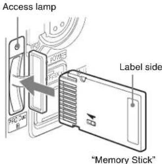
Insert a "Memory Stick" with the label side facing left into the "Memory Stick Duo" slot until it clicks and the access lamp lights in red.
When the "Memory Stick" is properly set, the lamp lights in green.
Note
If it does not fit into the slot properly or if there is some resistance when you insert it, the "Memory Stick" may be turned around or upside-down. Do not force the "Memory Stick" into the slot. Confirm the direction of the notch and arrow on the "Memory Stick" before inserting the "Memory Stick," and then try inserting it again.
Removing a "Memory Stick"
Confirm that the access lamp is not lit in red, then lightly push in the "Memory Stick" to release the lock.
Note
If the access lamp is lit in red, data is being read from or written to the "Memory Stick." At this time, do not shake the product or subject it to shock. Do not turn off the power to the product or remove the "Memory Stick." Doing so may damage the data.
Protecting saved data
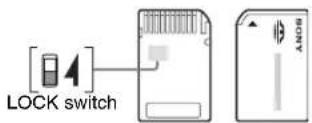
To prevent accidental erasure of important setup data, use the LOCK switch on the "Memory Stick."
Slide the switch upward to the write protect position.
This ensures that you cannot inadvertently overwrote data on the "Memory Stick."
Note
When using "Memory Stick" media that does not have a LOCK switch, be careful not to inadvertently overwrite or erase your data.
Precautions
- Do not attach anything other than the supplied label to the "Memory Stick" labeling position.
- Attach the label so that it does not stick out beyond the labeling position.
- Carry and store the "Memory Stick" in its case.
- Do not touch the connector of the "Memory Stick" with anything, including your finger or metallic objects.
- Do not strike, bend, or drop the "Memory Stick."
- Do not disassemble or modify the "Memory Stick."
- Do not allow the "Memory Stick" to get wet.
- Do not use or store the "Memory Stick" in a location that is: — Extremely hot, such as in a car parked in the sun
— Under direct sunlight
— Very humid or subject to corrosive substances
- To prevent data loss, make backups of data frequently. In no event will Sony be liable for any loss of data.
-
Unauthorized recording may be contrary to the provisions of copyright law. When you use a "Memory Stick" that has been pre-recorded, be sure that the material has been recorded in accordance with copyright and other applicable laws.
-
"Memory Stick" and are trademarks of Sony Corporation.
- "Memory Stick Duo" and a trademarks of Sony Corporation.
- "Memory Stick PRO Duo" and MEMORY STICK PRO Duo trademarks of Sony Corporation.
Specifications
| General | |
| Power requirements 240 V AC, 1.2 A (max.) | |
| 180 V DC, 1.1 A (max.) | |
| 12 V DC, 10 A (max.) | |
| Operating temperature | -20°C to +45°C (-4°F to +113°F) |
| Storage temperature | -20°C to +60°C (-4°F to +140°F) |
| Mass Approx. 3.8 kg (8 lb 6 oz) (the main unit only) | |
| Input/output connectors | |
| CCU Optical/electrical multi-connector (1) | |
| CAM-MAIN(L) SDI IN, CAM-SUB(R) SDI IN | BNC type (1 each) |
| CAM-MAIN(L) REF OUT, CAM-SUB(R) REF OUT | BNC type (1 each) |
| SDI 1 OUT, SDI 2 OUT BNC type (1 each) | |
| TEST OUT | BNC type (1) |
| PROMPTER1/GENLOCK IN | BNC type (1), 1 Vp-p, 75 ohms |
| VF | 20-pin (1) |
| AUDIO IN 1, AUDIO IN 2 | XLR 3-pin, female (1 each)For MIC: -60 dBu (variable up to -20 dBu by menu or HDCU1000/1500 operation), balancedFor LINE: 0 dBu, balanced |
| INTERCOM | XLR 5-pin, female (1 each) |
| DC IN | XLR 4-pin (1), 10.5 to 17 V DC |
| CAM-MAIN(L) DC OUT | XLR 4-pin, female (1), 10.5 to 17 V DC, 5.5 A ^1) maximum |
| CAM-SUB(R) DC OUT | XLR 4-pin, female (1), 10.5 to 17 V DC, 4 A ^1) maximum |
| DC OUT 4A max | XLR 4-pin, female (1), 10.5 to 17 V DC, 4 A ^1) maximum |
| DC OUT 0.5A max | 4-pin (1), 10.5 to 17 V DC, 500 mA ^1) maximum |
| CAM-MAIN(L) REMOTE, CAM-SUB(R) REMOTE | 8-pin (1 each) |
| REMOTE | 8-pin (1) |
| AUX | 12-pin (1) |
| RET CTRL | 6-pin (1) |
| TRACKER | 10-pin (1) |
| CRANE | 12-pin (1) |
| Supplied accessories | |
| Operation manual (1) | |
| Cable clamp belt (1) | |
| Optional accessories | |
| HD Electronic ViewfinderHDVF-C550W (5-type, color)HDVF-C730W (6.5-type, color)HDVF-C950W (9-type, color)HDVF-EL75 (7.4-type, color) | |
| "Memory Stick Duo," "Memory Stick PRO Duo" | |
| Related equipment | |
| HDCU1000/1500 HD Camera Control Unit | |
| HKCU-HB10/HB15 3G Fiber Transmission Unit | |
| HKCU1005 SDI Output Expansion Unit | |
| HKCU2005 3G Single Link Interface Unit | |
| HDC-P1 HD Multi Purpose Camera | |
| HDC1500R/1400R/1600R/1500/1600 HD Color Camera | |
| F35 Digital Cinematography Camera | |
| MSU-1000/1500 Master Setup Unit | |
| RCP-1000-series Remote Control Panel | |
1) May be limited with the status of load, input (see page 14)
For the customers in the U.S.A., Canada, Europe, Australia, and New Zealand
Connectors for optical/electric composite cables:
- L E M RUW.3K.93C.TLCC96 (to the "CAMERA" connector on CCU)
- L E M EDW.3K.93C.TLC (to the "CCU" connector on an HDFA-200)
Caution on the optical/electric composite cable:
For connection between the camera control unit and an HDFA-200, be sure to use an optical/electric signal composite cable with the connectors specified in this manual in order to comply with the limit for EMC regulations.
Design and specifications are subject to change without notice.
Note
Always verify that the unit is operating properly before use. SONY WILL NOT BE LIABLE FOR DAMAGES OF ANY KIND INCLUDING, BUT NOT LIMITED TO, COMPENSATION OR REIMBURSEMENT ON ACCOUNT OF THE LOSS OF PRESENT OR PROSPECTIVE PROFITS DUE TO FAILURE OF THIS UNIT, EITHER DURING THE WARRANTY PERIOD OR AFTER EXPIRATION OF THE WARRANTY, OR FOR ANY OTHER REASON WHATSOEVER.
Additional Functions of an MSU-1000/1500 in 3D Operations
Operations of CCU 3D Monitor functions
1 Select CCU on the Maintenance menu screen.
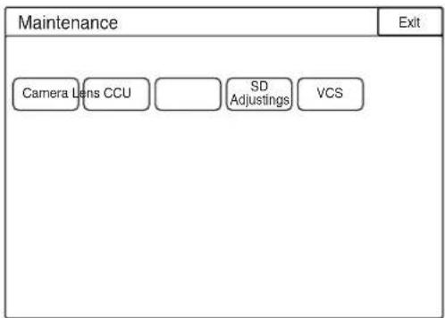
2 Select 3D Monitor.
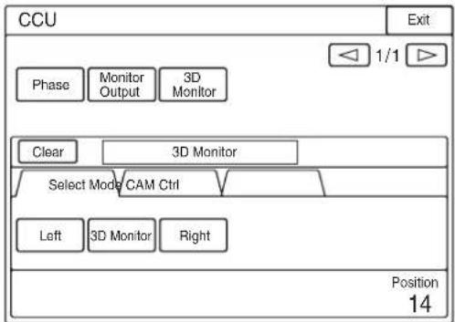
flowchart
graph TD
    A["Phase"] --> B["Monitor Output"]
    B --> C["3D Monitor"]
    D["Clear"] --> E["3D Monitor"]
    E --> F["Select Mode CAM Ctrl"]
    F --> G["Left"]
    F --> H["3D Monitor"]
    F --> I["Right"]
    J["Position 14"] --> K
3 Select a signal to be output from the Monitor Output connector of a CCU on the Select tab. For a CCU with an HKCU2005 3G Signal Link Interface Unit mounted, 3D Monitor can be selected.
4 Select a function to be used on the Mode tab.
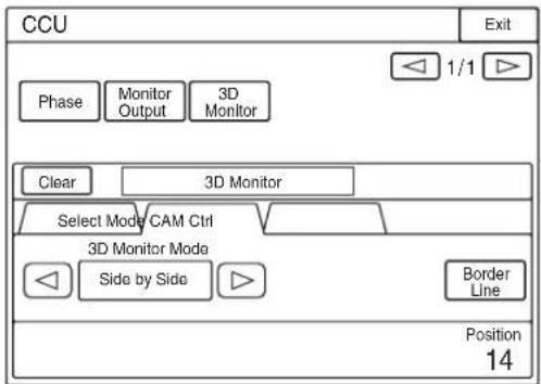
5 Move the border line by pressing the Border Line if the Split or Mirror function is selected.
6 Select a camera to be controlled in 3D mode with the buttons of 3D Camera Control on the CAM Ctrl tab.
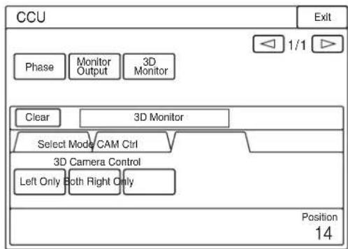
flowchart
graph TD
    A["Phase"] --> B["Monitor Output"]
    B --> C["3D Monitor"]
    D["Clear"] --> E["3D Monitor"]
    E --> F["Select Mode CAM Ctrl"]
    F --> G["3D Camera Control"]
    G --> H["Left Only Both Right Only"]
    H --> I["Position 14"]
The same selection can be made on the 3D CAM Control page of the Configuration menu.
Setting the 3D Mode
1 Select 3D System on the Configuration menu screen.
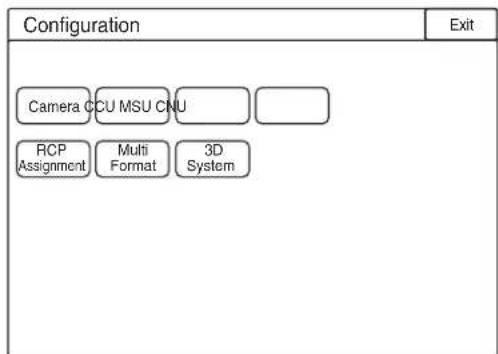
2 Select 3D Mode.
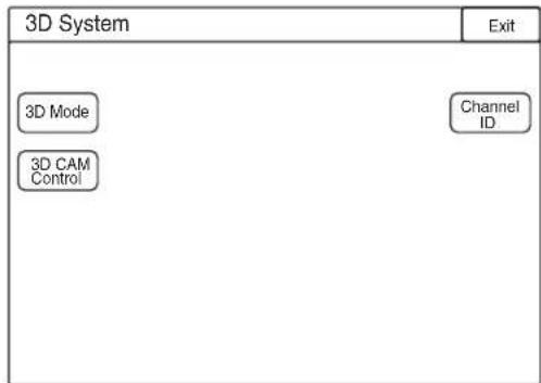
flowchart
graph TD
    A["3D System"] --> B["3D Mode"]
    A --> C["3D CAM Control"]
    D["Exit"] --> E["Channel ID"]
3 Set 3D Mode to ON.
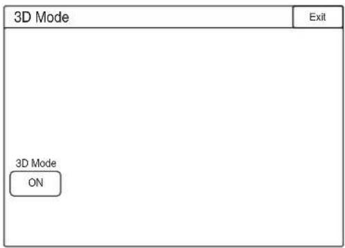
3D mode is set.
Setting the Channel ID
Channel ID is a function to display the identifier of the output signal to distinguish the two HD signals in Dual-Link or 3D-L/R connection.
1 Select 3D System on the Configuration menu screen.
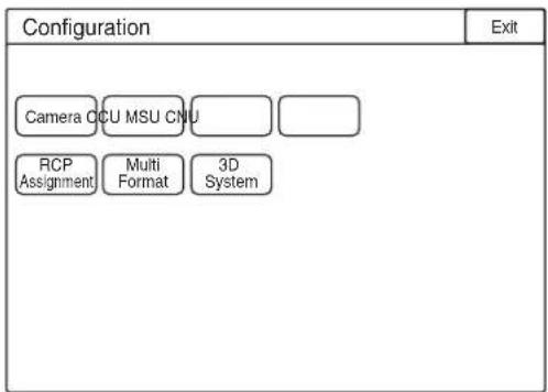
2 Select Channel ID.
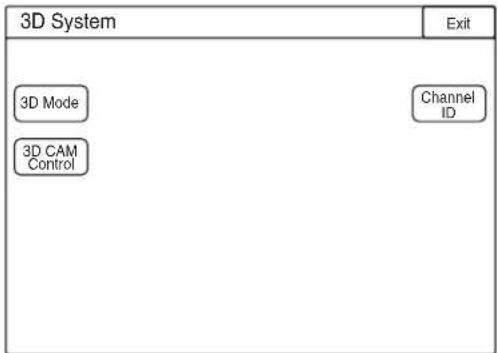
flowchart
graph TD
    A["3D System"] --> B["3D Mode"]
    A --> C["3D CAM Control"]
    D["Exit"] --> E["Channel ID"]
3 Set Channel ID to ON.
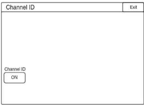
Setting the 3D Camera Control
When 3D Mode is set to ON, two cameras are normally controlled simultaneously. Some items for painting can be controlled separately to match the color tone between the two cameras. If Left Only or Right Only is selected, specified items of the selected camera can be controlled.
The 3D Camera Control function enables setting the switches for this function on the panel.
1 Select 3D System on the Configuration menu screen.
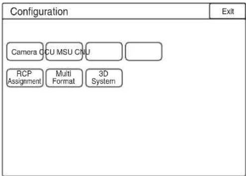
2 Select 3D CAM Control.
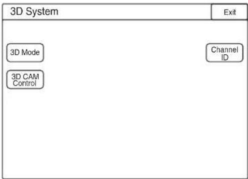
3 Select a camera to be controlled.
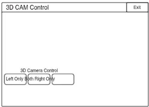
The same selection can be made with 3D Monitor on the CCU page of the Maintenance menu.
Menu Tree
The material contained in this manual consists of information that is the property of Sony Corporation and is intended solely for use by the purchasers of the equipment described in this manual.
Sony Corporation expressly prohibits the duplication of any portion of this manual or the use thereof for any purpose other than the operation or maintenance of the equipment described in this manual without the express written permission of Sony Corporation.
产品中有害物质的名称及含量
使用环境条件:
参考使用说明书中的操作条件
- WARNING
- AVERTISSEMENT
- For the customers in the U.S.A.
- For the customers in Canada
- For the customers in Europe
- CAUTION
- Laser Diode Properties
- 关于废弃产品的处理
- Installation and Connections 14
- Preparatory Settings.... 22
- Menus.... 24
- Appendices.... 34
- Compatible Devices
- About this manual
- Overview
- Features
- Improving operation efficiency by connecting a single fiber cable
- 3D multicamera operation
- Improving operation with a single remote control panel
- 3D monitoring with a viewfinder
- Linking with an MPE-200 with lens meta data
- Remote operation of a 3D rig 1) using a trunk data line
- Improving half-mirror rig operation, using an H/V inverting function
- Simplifying system configuration for HDC-P1 operation
- Lightweight and compact design enabling a flexible operation
- System Configuration
- Notes
- 3D multicamera system operation example
- System operation example with a Digital Cinematography Camera F35
- Parts Identification
- ①Camera Control Unit (CCU) connector (optical fiber connector)
- ②Cable clamp belt attachment screw holes
- Rear panel
- ①INTERCOM connector (XLR 5-pin)
- ②PGM1 (Program 1) knob
- ③PGM2 (Program 2) knob
- ④RET 1 (return video 1) button
- ⑤ RET (return video) button and 2/3/4 (return video 2/3/4) select switch
- Note
- ⑥ "Memory Stick Duo" slot and access lamp
- ⑦CAMERA POWER switch and indicator
- ⑧CALL button
- ⑨Line select switch
- ⑩MIC (microphone) switch
- ⑪ INTERCOM level control
- ⑫DISPLAY switch
- ⑬Menu control knob (rotary encoder)
- ⑭ASSIGNABLE button
- 15VF SOURCE switches
- L/BOTH/R switch
- MIX/SPLIT/DIFF switch
- CAM/HD PROMPT switch
- Side panel
- ①CAM-MAIN(L) connectors (BNC type)
- ②CAM-SUB(R) connectors (BNC type)
- ③SDI1 OUT (serial digital interface) connector (BNC type)
- ④SDI2 OUT (serial digital interface) connector (BNC type)
- ⑤TEST OUT connector (BNC type)
- ⑥PROMPTER1/GENLOCK IN (prompter 1 signal output/external sync signal input) connector (BNC type)
- ⑦CAM-MAIN(L) REMOTE connector (8-pin)
- ⑧ CAM-SUB(R) REMOTE connector (8-pin)
- ⑨REMOTE connector (8-pin)
- ⑩VF (viewfinder) connector (20-pin)
- ①CAM-MAIN(L) DC OUT connector
- ⑫CAM-SUB(R) DC OUT connector
- AUDIO IN 1 connector (XLR 3-pin) and select switches
- Audio input select switch
- Microphone power switches
- AUDIO IN 2 connector (XLR 3-pin) and select switch
- ⑮DC IN (DC power supply input) connector (XLR 4-pin)
- ⑯DC OUT (DC power supply output) 4A max connector (4-pin)
- ⑰AUX connector (12-pin)
- ⑱CRANE connector (12-pin)
- TRACKER connector (10-pin)
- 20RET CTRL (return control) connector (6-pin)
- ②DC OUT (DC power supply output) 0.5A max connector (4-pin)
- Installation and Connections
- Notes on Power Supplied from This Unit
- Limit of power supply according to the cable length
- When connecting to an HDCU1000
- When connecting to an HDCU1500
- Mounting the Unit to a Tripod
- Mounting on a Rig
- Connecting Cameras
- Settings when connecting HDC-P1 cameras
- To set on an HDFA-200
- To set on an HDC-P1
- Settings when connecting HDC1500R-series cameras
- To set on an HDC1500R-series camera
- Connecting an F35
- Settings when connecting an F35 (2D mode)
- To set on an MSU or RCP
- To set on a CCU
- Connecting a Camera Control Unit (CCU)
- Connecting the unit and a CCU
- Using the cable clamp belt
- Connecting a CCU in 3D mode
- To connect an HDCU1000
- To connect an HDCU1500
- Attaching a Viewfinder
- Attaching a viewfinder to the unit
- Remove the four plastic caps from the viewfinder attaching holes.
- Attach the V-wedge shoe attachment (supplied with the viewfinder) to the unit using the hexagonal wrench (supplied with the viewfinder) and four hexagonal screws (4×12, supplied with the viewfinder).
- Mount the viewfinder firmly in the V-wedge shoe attachment.
- Screen display of the viewfinder
- When the DISPLAY switch is set to ON
- ①TALK indication
- ②EX (lens extender) indication
- ③Zoom position indication
- ④Battery voltage indication
- ⑤ Focus position indication
- 65600K mode indication
- ⑦Filter indication
- ⑧Gain value indication
- ⑨Shutter/ECS indication
- 10RET indication
- ⑪F-value indication
- ① Assignable button indication
- ②Format indication
- ③‘!’ indication area
- ④Light-receiving level indications
- When the DISPLAY switch is set to OFF
- Press the menu control knob.
- The items shown below can be changed with the MIX/SPLIT/DIFF switch.
- Preparatory Settings
- Setting the 3D Mode
- When a Camera Control Unit is connected
- To make setting on an MSU or RCP
- To set it on a CCU
- When an HDFA-200 is used as a standalone device
- Setting the Output Format
- Setting the Picture Inverting Function for a Rig
- Menus
- Displaying Menu Pages
- Displaying a menu page
- Displaying the TOP MENU screen
- Setting the Menu
- Selecting a menu on the TOP MENU screen
- Selecting a page from a CONTENTS page
- Changing the displayed page
- Check that the pointer is located at the left of the page number then push on the menu control knob.
- Rotate the menu control knob to flip through the pages, and push on the knob when the desired page is displayed.
- To return to the TOP MENU screen
- Setting the Menu Items
- Align the pointer with the desired item, then push on the menu control knob.
- Rotate the menu control knob to change the setting value.
- To interrupt settings
- Push on the menu control knob.
- To change other setting items on the same menu page, repeat steps 1 through 3.
- Specifying a character string
- Set the cursor to the position where you wish enter a character, then push on the menu control knob.
- Set the cursor to the character to be entered and push on the menu control knob.
- Select END and push on the menu control knob.
- Returning a menu item to its standard value
- Ending menu operations
- Editing the USER Menu
- Editing by items
- To add items to a page
- Select USER MENU CUSTOMIZE on the TOP MENU screen (page 24).
- If the CONTENTS page is displayed, turn the menu control knob to move the pointer to any of USER 1 EDIT to USER 19 EDIT then push on the menu control knob to display the page.
- Move the pointer to INSERT and push on the menu control knob.
- Add the items.
- Add the remaining items by repeating steps 3 to 5.
- To change the order of items on a page
- Select MOVE then push on the menu control knob.
- Move the pointer to the position where you wish to move the item then push on the menu control knob.
- Deleting items from a page
- Inserting a blank line
- Editing by pages
- Adding a page
- Deleting a page
- Changing the order of pages
- Move the pointer to the position where you wish to move the page then push on the menu control knob.
- OPERATION Menu
- FILE Menu
- DIAGNOSIS Menu
- Appendices
- Notes on Use
- Use and storage locations
- Avoid violent impacts
- Do not cover with cloth
- After use
- Care
- Error Messages
- Using a "Memory Stick"
- Inserting a "Memory Stick"
- Removing a "Memory Stick"
- Protecting saved data
- Precautions
- For the customers in the U.S.A., Canada, Europe, Australia, and New Zealand
- Caution on the optical/electric composite cable:
- Additional Functions of an MSU-1000/1500 in 3D Operations
- Operations of CCU 3D Monitor functions
- Select CCU on the Maintenance menu screen.
- Select 3D Monitor.
- Select a signal to be output from the Monitor Output connector of a CCU on the Select tab. For a CCU with an HKCU2005 3G Signal Link Interface Unit mounted, 3D Monitor can be selected.
- Select a function to be used on the Mode tab.
- Move the border line by pressing the Border Line if the Split or Mirror function is selected.
- Select a camera to be controlled in 3D mode with the buttons of 3D Camera Control on the CAM Ctrl tab.
- Select 3D System on the Configuration menu screen.
- Select 3D Mode.
- Set 3D Mode to ON.
- Setting the Channel ID
- Select Channel ID.
- Set Channel ID to ON.
- Setting the 3D Camera Control
- Select 3D CAM Control.
- Select a camera to be controlled.
- Menu Tree
- 产品中有害物质的名称及含量
Brand : SONY
Model : HDFA-200
Category : Optical Adapter