
HCRB-2424i - Hob APW Wyott - Free user manual and instructions
Find the device manual for free HCRB-2424i APW Wyott in PDF.


| Product Type | Heavy Duty Charrock Gas Broiler |
| Model | HCRB-2424i |
| Brand | APW Wyott |
| Width | 24 inches (609.6 mm) |
| Depth | 34.339 inches (872 mm) |
| Height | 15.217 inches (386.5 mm) |
| Number of Burners | 4 |
| BTU per Burner (Natural Gas) | 20,000 BTU (5.86 kW) |
| Total BTU (Natural Gas) | 80,000 BTU (23.4 kW) |
| Gas Supply Pressure (Natural Gas) | 5 inches WC (12.4 mbar) |
| Gas Type | Natural Gas (convertible to LP with included orifices) |
| Ignition | Standing pilot (pilot safety valve optional) |
| Construction Material | Stainless steel exterior and firebox |
| Cooking Grates | Heavy duty reversible grates for branding marks |
| Radiants | Stainless steel radiants (cast iron optional) |
| Legs | 4 adjustable legs, 2-inch diameter heavy duty |
| Clearances (non-combustible surfaces) | 0 inches sides and rear, 4 inches floor |
| Safety Features | Thermocouple pilot safety, manual gas shutoff valve |
| Maintenance | Daily grate burn-off, weekly cleaning of radiants and burners |
| Warranty | 1 year parts and labor (extended on certain components) |
Frequently Asked Questions - HCRB-2424i APW Wyott
User questions about HCRB-2424i APW Wyott
0 question about this device. Answer the ones you know or ask your own.
Ask a new question about this device
Download the instructions for your Hob in PDF format for free! Find your manual HCRB-2424i - APW Wyott and take your electronic device back in hand. On this page are published all the documents necessary for the use of your device. HCRB-2424i by APW Wyott.
USER MANUAL HCRB-2424i APW Wyott
Heavy Duty Gas Char-Broilers
MODELS: HDCB-2424i, HDCB-2436i, HDCB-2448i, HDCB-2460i, HDCB-2472i
&
Heavy Duty Charrock Gas Broilers
MODELS: HDCRB-2424i, HDCRB-2436i, HDCRB-2448i, HDCRB-2460i, HDCRB-2472i
IMPORTANT FOR FUTURE REFERENCE
Please complete this information and retain this manual for the life of the equipment. For Warranty Service and/or Parts, this information is required.
Model Number Serial Number Date Purchased

FOR YOUR SAFETY: Do not store or use gasoline or other flammable vapors or liquids in the vicinity of this or any other appliance.


WARNING: Improper installation, adjustment, alteration, service or maintenance can cause property damage, injury or death. Read the installation, operating and maintenance instructions thoroughly before installing, or servicing this equipment.


WARNING: Instructions must be posted in a prominent location. All safety precautions must be taken in the event the user smells gas. Safety information can be obtained from your local gas supplier.



P/N 8822211 09/26/13
APW Wyott MANUFACTURING
DALLAS:
1307 N. Watters Rd #180 · Allen, TX · 75013
Local: (972) 908-6100 Local: (307) 634-5801
Toll Free: (800) 431-2745 Toll Free: (800) 752-0863
Parts/Service Fax: (214) 565-0976 Parts/Service Fax: (214) 565-0976
CHEYENNE:
1938 Wyott Dr • Cheyenne, WY • 82007
TABLE OF CONTENTS:
| ITEM | PAGE | ITEM | PAGE |
| Safety Precautions | 3 | Cleaning/Maintenance | 13 |
| General Installation Instructions | 4 | Service/Repair | 14 |
| Specifications & Dimensions | 5 | Troubleshooting Guide | 14 |
| Conversion | 9 | Replacement Parts Lists & Exploded Views | 15 |
| Lighting Instructions | 10 | Warranty | 22 |
| Operating Instructions | 12 |

CAUTION: These models are designed, built, and sold for commercial use. If these models are positioned so the general public can use the equipment, make sure that cautions, warnings, and operating instructions are clearly posted near each unit so that anyone using the equipment will use it correctly and not injure themselves or harm the equipment.


WARNING: Improper installation, adjustment, alteration, service or maintenance can cause property damage, injury or death. Read the installation, operating and maintenance instructions thoroughly before installing or servicing this equipment.


WARNING: For your safety do not store or use gasoline or other flammable vapors and liquids in the vicinity of this or any other appliance. Keep the area free and clear of combustibles. (See ANZI Z83. 14B, 1991).


NOTICE: Instructions to be followed if anyone smells gas should be posted in a prominent place. These may be obtained from the gas supplier.

GAS PRESSURE
The appliance and it's individual shutoff valve (to be supplied by user) must be disconnected from the gas supply piping system during any pressure testing of that system at test pressures in excess of 1/2 psi (3.45 kPa). NOTE: Gas shutoff valve is supplied on CE models.
The appliance must be isolated from the gas supply piping system by closing it's individual manual shut-off valve during any pressure testing of the gas supply piping system at test pressures equal to or less than 1/2 psi (3.45 kPa).

WARNING: A factory authorized agent should handle all maintenance and repair. Before doing any maintenance or repair, contact APW Wyott

Congratulations on your purchase of APW Wyott commercial cooking equipment. APW Wyott takes pride in the design and quality of our products. When used as intended and with proper care and maintenance, you will experience years of reliable operation from this equipment. To ensure best results, it is important that you read and follow the instructions in this manual carefully.
LOCATION OF DATAPLATE
The data plate is located on the right side panel
IMMEDIATELY INSPECT FOR SHIPPING DAMAGE
All containers should be examined for damage before and during unloading. The freight carrier has assumed responsibility for its safe transit and delivery. If equipment is received damaged, either apparent or concealed, a claim must be made with the delivering carrier.
A) Apparent damage or loss must be noted on the freight bill at the time of delivery. It must then be signed by the carrier representative (Driver). If this is not done, the carrier may refuse the claim. The carrier can supply the necessary forms.
B) Concealed damage or loss if not apparent until after equipment is uncrated, a request for inspection must be made to the carrier within 15 days. The carrier should arrange an inspection. Be certain to hold all contents and packaging material.
Installation and start-up should be performed by a qualified installer who thoroughly read, understands and follows these instruction.
If you have questions concerning the installation, operation, maintenance or service of this product, write Technical Service Department APW Wyatt, 1307 N Watters Rd # 180, Allen, TX 75013
SAFETY PRECAUTIONS

DANGER: This symbol warns of imminent hazard which will result in serious injury or death.


WARNING: This symbol refers to a potential hazard or unsafe practice, which could result in serious injury or death.


CAUTION: This symbol refers to a potential hazard or unsafe practice, which may result in or moderate injury or product or property damage.


NOTICE: This symbol refers to information that needs special attention or must be fully understood even though not dangerous.


NOTICE: This product is intended for commercial use only. Not for household use.


CAUTION: These models are designed, built, and sold for commercial use. If these models are positioned so the general public can use the equipment make sure that cautions, warnings, and operating instructions are clearly posted near each unit so that anyone using the equipment will use it correctly and not injure themselves or harm the equipment.


WARNING: Improper installation, operation, service or maintenance can cause property damage, injury or death. Read and understand these instructions thoroughly before positioning, installing, maintaining or servicing this equipment.


NOTICE: Local codes regarding installation vary greatly from one area to another. The National Fire Protection Association, Inc., states in its NFPA96 latest edition that local codes are “Authority Having Jurisdiction” when it comes to requirement for installation of equipment. Therefore, installation should comply with all local codes.

GENERAL INSTALLATION INSTRUCTIONS
Ensure gas supply and gas type, as shown on unit nameplate agree.
Unit installation must conform with the National Fuel Gas Code, ANSI Z223.1/NFPA 54, the National Gas Installation Code, CSA-B149.1, or the Propane Installation Code, CSA-B149.2 as applicable and in accordance with local codes.
Screw legs into the permanently fastened nuts on the four corners of the unit and tighten by hand. Level the unit by turning the adjustment screw at the bottom of each leg. Do not slide unit with legs mounted, lift if necessary to move unit.
Pipe threading compound must be resistant to the action of liquefied petroleum gases.
Caution: DO NOT use an open flame to check for leaks. Check all gas piping for leaks with a soap and water solution before operating unit.
THESE UNITS ARE SUITABLE FOR INSTALLATION ON NON-COMBUSTIBLE SURFACES ONLY.
Noncombustible clearances:
0" sides (0 mm)
0" rear (0 mm)
4" floor (102mm)
Do not obstruct the flow of combustion and ventilation air, under the unit by the legs or behind the unit by the flue.
Adequate clearance for air openings into the combustion chamber is required. Do not place objects between the bottom of the unit and the counter top.
There must be adequate clearance for removal of the front panel. All major parts except the burners are removable thru the front if the gas line is disconnected.
Unit must have adequate clearances for servicing. (Sides = 0", Rear = 0", Floor = 4").
European Community Installation Instructions:
"THIS APPLIANCE MUST BE FITTED BY A COMPETENT PERSON. IN THE UK, CORGI REGISTERED INSTALLERS (INCLUDING THE REGIONS OF BRITISH GAS) UNDERTAKE TO WORK TO SAFE AND SATISFACTORY STANDARDS. THIS APPLIANCE MUST BE INSTALLED IN ACCORDANCE WITH THE GAS SAFETY (INSTALLATION AND USE) REGULATIONS AND THE RELEVANT BUILDING REGULATIONS / IEE. REGULATIONS. DETAILED RECOMMENDATIONS ARE CONTAINED IN THE FOLLOWING BRITISH STANDARD CODES OF PRACTICE - BS 6172, BS 5440 PART 2, BS 6891"
"THIS APPLIANCE MUST BE INSTALLED IN ACCORDANCE WITH THE RULES IN FORCE"
"MUST BE INSTALLED IN A WELL VENTILATED AREA. Ventilation requirements ie. B.S. 5440."
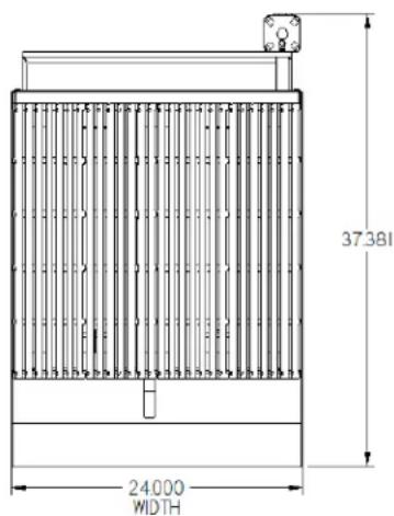
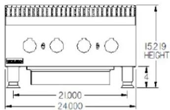
SPECIFICATIONS AND DIMENSIONS
| MODEL | WIDTH IN. (MM) | DEPTH IN. (MM) | HEIGHT IN. (MM) | # OF BURNERS | BTU/kW BURNER NATURAL GAS | TOTAL BTU/kW HOUR | W.C IN. ('Mbar') |
| HDCB-2424i | 24" (609.6) | 34.339" (872) | 15.217" (386.5) | 4 | 20,000 (5.86) | 80,000 (23.4) | 5 (12.4) |
| HDCB-2436i | 36" (914.4) | 34.339" (872) | 15.217" (386.5) | 6 | 20,000 (5.86) | 120,000 (35.2) | 5 (12.4) |
| HDCB-2448i | 48" (1219.2) | 34.339" (872) | 15.217" (386.5) | 8 | 20,000 (5.86) | 160,000 (46.9) | 5 (12.4) |
| HDCB-2460i | 60" (1524.0) | 34.339" (872) | 15.217" (386.5) | 10 | 20,000 (5.86) | 200,000 (58.6) | 5 (12.4) |
| HDCB-2472i | 72" (1828.8) | 34.339" (872) | 15.217" (386.5) | 12 | 20,000 (5.86) | 240,000 (70.3) | 5 (12.4) |
| HDCRB-2424i | 24" (609.6) | 34.339" (872) | 15.217" (386.5) | 4 | 20,000 (5.86) | 80,000 (23.4) | 5 (12.4) |
| HDCRB-2436i | 36" (914.4) | 34.339" (872) | 15.217" (386.5) | 6 | 20,000 (5.86) | 120,000 (35.2) | 5 (12.4) |
| HDCRB-2448i | 48" (1219.2) | 34.339" (872) | 15.217" (386.5) | 8 | 20,000 (5.86) | 160,000 (46.9) | 5 (12.4) |
| HDCRB-2460i | 60" (1524.0) | 34.339" (872) | 15.217" (386.5) | 10 | 20,000 (5.86) | 200,000 (58.6) | 5 (12.4) |
| HDCRB-2472i | 72" (1828.8) | 34.339" (872) | 15.217" (386.5) | 12 | 20,000 (5.86) | 240,000 (70.3) | 5 (12.4) |
HDCB & HDCRB-2424i, 24" GAS CHAR BROILER
22211240

CONVERSION
• Instructions are for conversion from Natural Gas to Propane (L.P.) on all models HDCRB & HDCB.
• The conversion should be done before connecting the unit to the gas supply.
- Units are shipped from the factory equipped for use on natural gas. Orifices necessary for LP (propane) are provided in a bag tied to the valve on the front panel.
-
Remove the knobs and front panel.
-
Remove the orifice fittings from the valve. Change the orifices to the size recommended for propane (L.P.).
-
Replace the orifice fittings into the valve.
• To change the regulator:


- Connect the regulator to the unit, connect gas and check for leaks. WARNING: Do not use an open flame to check for leaks.
- Check the system pressure. With the front panel removed remove the plug – from the manifold.
- Place a fitting in the plug opening and connect a manometer.
- For Natural gas the pressure in the manifold should be 5" water column or 12.4 millibar. For LP the pressure in the manifold should be 10" water Column of 24.9 millibar.
- To adjust the pressure remove the brass cap and turn the white plastic part inside the stem of the regulator. See picture regulator 8.
- Take a wide straight screw driver and place it in the two notches shown in picture regulator 7 turn clockwise to increase pressure and counter-clockwise to reduce pressure. See picture regulator 8.
• Once the pressure has been adjusted replace the brass cap.
- Note the blue cap on the regulator, this is the vent there are openings below the top rim. NEVER block these openings your regulator will fail to operate correctly. On at least a monthly basis blow off any dust
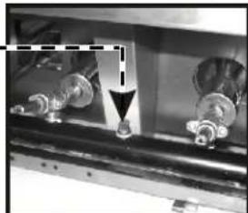
or grease which may accumulate around this cap. The openings must remain open for the regulator to function. Clean more often in a very greasy atmosphere.
LIGHTING INSTRUCTIONS
HDCB and HDCRB Broilers are furnished with either a pilot safety valve or a standing pilot (not available in the European Community). Please follow the instructions for your unit.
Pilot Operation Flame Failure Gas Valve:
Operation of the gas valve pilot:
- Turn knob on the main gas valve to the pilot position
- Depress knob to start gas flow to the pilot valve
- Light pilot valve
a. Using a match or taper
- Hold in knob for 15 to 30 seconds to heat up the thermocouple
- Release knob and turn to the desired gas flow position
a. If pilot goes out repeat steps 1-4, some thermocouples will take longer to heat up
Standing Pilot Lighting Instructions: (Not Available in the European Community)
The pilot lights on the broilers have been set at the factory. A screwdriver may be required for the first lighting to adjust the flame for your elevation.
- Turn off the manual shut off valve and wait 5 minutes to clear the gas.
- Turn all knobs to the "OFF" position.
- The valve can be accessed through an opening in the front panel or remove the cooking grates and light the pilot from above.
- Turn the manual shut off valve on.
- Hold an ignition source (match) to both openings on the pilot tube. When the flames are established, remove the ignition source.
- Turn the burner knobs to "HI". If the burner does not ignite, promptly open the pilot valve more. If the pilot flame appears larger than necessary, turn it down and reset burner ignition. The pilot flame should be as small as possible but large enough to guarantee reliable ignition of the burners when the knobs are turned to "HI".
RELIGHTING PILOT
If the pilot light should go out for any reason:
- Promptly shut off all gas at the manual shut off valve.
• Turn off all knobs and pilot valves; wait 5 minutes to clear gas. - Relight following steps 4 through 6 under Standing Pilot Lighting Instructions.
LIGHTING MAIN BURNER:
Since the burner is lit from constantly burning pilot, turn knobs to "HI" to put the unit in operation; then adjust to any desired position between "LO" and "HI".
- To light burner, turn knob to "max." then back off to the desired flame level. The range of adjustment is virtually infinite between high and off. (At the small flame, there is a pre-set low).
- When the broiler is first heated, it will smoke until oil used in manufacturing, preservation and dust from storage and shipping are burned off. An hour at "max." on all burners is usually sufficient.
-
Turn knobs off and let cool.
-
For first cooking, set the grates at maximum tilt position and preheat before broiling. You will have to experiment with knob settings and grate position for each particular item.
- Keep the grease/water pan with sufficient water to cover the entire bottom.
- Clean regularly. Grates may be removed for washing in the sink. Brush out carbonized particles. Thoroughly wash the grease/water pan.
CAUTION
Never attempt to move a grill section while cooking. An unexpected flare could cause severe injury. Turn off the unit, let it cool and use potholders and/or gloves to reposition or remove. The space between the legs at the bottom admits combustion air. DO NOT BLOCK THIS SPACE.
Main burner air supply:
For efficient burner operation, a proper balance of gas volume and primary air supply must be maintained which will result in complete combustion. Insufficient air supply results in a yellow streaming flame. Primary air supply is controlled by an air shutter on the front of the burner.
Loosen the screws on the front of the burner, and adjust the air shutter to just eliminate the yellow tips of the burner flame. Lock the air shutter in place by tightening the screws.
European Community:
If adjustment becomes necessary in the field, it should be done by a factory authorized and trained technician who should seal the screw after the adjustment to safeguard against un-authorized tampering by the end user.
All burners are lit from constantly burning pilots. Turning the valve to the desired flame height is all that is required to put the unit in service.
Do not permit fans to blow directly at the unit. Wherever possible, avoid open windows next to the units' sides or back. Avoid wall type fans which create air cross-currents within a room.
It is also necessary that sufficient air should be allowed to enter the room to compensate for the amount of air removed by any ventilating system. Otherwise, a subnormal atmospheric pressure will occur, affecting operation and causing undesirable working conditions.
A properly designed and installed hood will act as the heart of the ventilating system for the room or area in which the unit is installed, and will leave the unit independent of changing draft conditions.
All valves must be checked and lubricated periodically. This must be done by an authorized service representative in your area.
OPERATING INSTRUCTIONS
OPERATION: Turn the burners on about 15-20 minutes before cooking for preheating. Set the knobs to the desired flame height or temperature. Each valve will control the gas flow to the burner to bring that area of the unit up to the set temperature. If different temperature settings are to be used, adjoining areas should be set at progressively higher temperatures using the lowest temperatures on the outside burners. A uniform and systematic approach to the loading of the unit will produce the most consistent product results.
RADIANTS
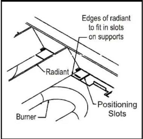
Place the radiants in their position as shown in Sketch 1. Make sure that the radiants are setting properly into the slots on the front and rear supports. Radiants should be centered over straight section of the burners.
COOKING GRATES
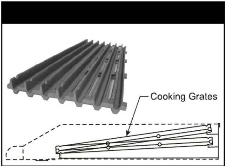
Place the top cooking grates with the grid bars sloping toward the front as shown in Sketch 2.
SEASON GRIDDLE
Heat to low temperature (300 - 350 F/150-180C) and pour on a small amount of cooking oil, about one ounce (30cc) per square foot of surface. Spread the oil over the entire griddle surface with a cloth to create a thin film. Wipe off any excess oil with a cloth. Repeat this procedure 2 to 3 times until the griddle has a slick, mirror-like surface.
NOTE: When cooking grates are placed sloping toward the front, the grooves on top will guide the excess fat drippings into the grease trough. For wider branding marks turn the cooking grate over so the product is placed on the wider rails. There is less grease removal with the cooking grates in this position so there will be a little more flare ups in this position.

CAUTION: Do not turn on gas valves without lighting the pilots. This could cause a build up of gas and potential explosion.

SKETCH 1 SKETCH
CLEANING / MAINTENANCE
INITIAL CLEANING:
Prior to operating your new broiler, thoroughly wash the exterior with a mild detergent or soap solution. Do not use abrasive cleaners, since this might damage the cabinet finish. If the stainless steel surfaces become discolored, scrub by rubbing only in the direction of the finished grain.
When the broiler is first heated, it will smoke until oil used in manufacturing, preservation and dust from storage and shipping are burned off. An hour at "max." on all burners is usually sufficient.
CLEANING:
DAILY
Remove the grease pan, empty and wash it.
Grate "burn off". The grease buildup on the grates should be cleaned daily (more often as needed).
A. Caution: When handling grates or radiants, always use insulated gloves to prevent burns.
B. Warning: Do not cover the top of the grid grates during a burn off operation. Restricting the airflow by covering the grid grates may cause them to warp. It will also cause damage to the valves, the knobs, the rock grates and the front panel decal.
C. Place grates on broiler, with grid bars horizontal, facing down.
D. Turn control knobs to "HI" for approximately 45 minutes.
E. Turn off the broiler and allow it to cool for 20 Minutes.
F. Clean top and bottom surfaces of grate with a wire brush to remove animal fats and carbonized grease.
G. Clean channels on grates with a scraper.
H. Remove grates from broiler. Clean top surface of radiants with the wire brush. They may be cleaned in place.
WEEKLY
Thoroughly clean the exposed surfaces of broiler, sides, front and top grease trough, with a damp cloth, then polish with a soft, dry cloth. A detergent may be used for cleaning. To remove discoloration, use a non-abrasive cleaner.
After performing daily cleaning procedures, proceed with the following:
A. Remove the radiants or rock grates. Clean reflecting drip shield of any dust or debris with a brush.
Note: Top cooking grates and rock grates are heavy. For applications where you use abundant sauces, radiants and rock grates should be cleaned more often.
B. Burner air shutter openings must be kept clean.
C. Burner ports must be kept clean. To clean burners, boil them in a strong solution of lye water for fifteen to twenty minutes. Then, either brush with a wire brush or clean gas ports with a sharp-pointed metal instrument to insure open ports.

CAUTION: Clean the regulator at least once a month. Make sure the vent opening is open and not blocked in any way. Failure to do so will cause variations in pressure. Your unit will not function as well and it could shorten the life of the product.

EXTENDED SHUTDOWN:
Turn the manual shutoff valve to "OFF"; (*field installed valve not supplied by the manufacturer), turn all control knobs to the "OFF" position and shut off the pilot flame by turning the adjustment on the pilot valve.
*NOTE: Gas shutoff valve is supplied by the manufacturer on CE or European Community models.
SERVICE / REPAIR
NOTE: THIS APPLIANCE MUST ONLY BE SERVICED BY AN AUTHORIZED AGENT.
NOTE: Parts protected by the manufacturer or his agent are not to be adjusted by the installer, unless the installer is an authorized service agent.
TROUBLESHOOTING GUIDE
| PROBLEM POSSIBLE CAUSE | |
| Heat does not come on when valve is turned on. | Pilot burner not lit. |
| Gas valve is bad. | |
| Pilot burner will not light. Obstructed pilot orifice. | |
| Pilot gas turned off at automatic pilot. | |
| Automatic pilot valve is bad. | |
| Gas is shut off to unit. | |
| Pilot burner will not stay lit. | Thermocouple is bad. |
| Thermocouple is not hot enough. | |
| Obstructed or wrong size pilot orifice. | |
| Gas supply is not purged of air. | |
| Air is blowing pilot light out. | |
| Automatic pilot valve is bad. | |
| Fat appears to smoke excessively. | Heat is set too high. |
| Moisture in the food may be turning into steam. | |
| Food sticks to grates. Heat is set too high. | |
| Griddle surface needs cleaning and/or seasoning. | |
| Surface under food may not have been covered with enough cooking oil. | |
| Food is undercooked inside. Heat is set too high. | |
| Food may not have been cooked for long enough time. | |
| Food tastes greasy or has objectionable off-flavor. | Food itself may have off flavor. |
| Food may have been stored improperly before cooking. | |
| Too much griddle fat used. | |
| Heat is set too low. | |
PLACE LAVA ROCKS OR GLO STONES WITH AIR SPACES BETWEEN THE ROCKS. DO NOT OVER
Please use the following amount of lava rocks or glo stones per model.
HDCRB 24" = Approximately 6 LBS.
HDCRB 36" = Approximately 9 LBS.
HDCRB 48" = Approximately 12 LBS.
HDCRB 60" = Approximately 15 LBS.
HDCRB 72" = Approximately 18 LBS.

EXPLODED VIEWS (Domestic Version)
PARTS LIST (DOMESTIC VERSION)
PARTS LIST (CE VERSION)
| HDCB & HDCRB - GAS CHAR BROILER (Page 1 of 2) | ||||||||||||
| Item P/N Description | Quantity | |||||||||||
| HDCB-2424i | HDCRB-2424i | HDCB-2436i | HDCRB-2436i | HDCB-2448i | HDCRB-2448i | HDCB-2460i | HDCRB-2460i | HDCB-2472i | HDCRB-2472i | |||
| 1 | 21825020 | Weldm't, Bullnose | 1 | |||||||||
| 21825120 | Weldm't, Bullnose | 1 | 1 | |||||||||
| 21825220 | Weldm't, Bullnose | 1 | 1 | |||||||||
| 21825320 | Weldm't, Bullnose | 1 | 1 | |||||||||
| 21825420 | Weldm't, Bullnose | 1 | 1 | |||||||||
| 2 | 21825433 | Side, Firebox | 2 | 2 | 2 | 2 | 2 | 2 | 2 | 2 | 2 | 2 |
| 3 | 21825036 | Face, 24" Firebox CE | 1 | 1 | ||||||||
| 21825136 | Face, 36" Firebox CE | 1 | 1 | |||||||||
| 21825236 | Face, 48" Firebox CE | 1 | 1 | |||||||||
| 21825338 | Face, 60" Firebox CE | 1 | 1 | |||||||||
| 21825438 | Face, 72" Firebox CE | 1 | 1 | |||||||||
| 4 | 21825017 | Support, Burner | 1 | 1 | ||||||||
| 21825117 | Support, Burner | 1 | 1 | |||||||||
| 21825216 | Support, Burner | 1 | 1 | |||||||||
| 21825316 | Support, Burner | 1 | 1 | |||||||||
| 21825416 | Support, Burner | 1 | 1 | |||||||||
| 5 | 21825037 | Baffle, Front Heat CE | 1 | 1 | ||||||||
| 21825137 | Baffle, Front Heat CE | 1 | 1 | |||||||||
| 21825237 | Baffle, Front Heat CE | 1 | 1 | |||||||||
| 21825339 | Baffle, Front Heat CE | 1 | 1 | |||||||||
| 21825439 | Baffle, Front Heat CE | 1 | 1 | |||||||||
| 6 | 21825134 | Divider, Firebox | NA | NA | 1 | 1 | 1 | 1 | 2 | 2 | 2 | 2 |
| 7 | 21825126 | Support, Firebox | NA | NA | 1 | 1 | ||||||
| 21825217 | Support, Firebox | 1 | 1 | |||||||||
| 21825317 | Support, Firebox | 1 | 1 | |||||||||
| 21825417 | Support, Firebox | 1 | 1 | |||||||||
| 8 | 21813085 | Spacer | 4 | 4 | 4 | 4 | 5 | 5 | 5 | 5 | 6 | 6 |
| 9 | 21829535 | Manifold, 24" CE | 1 | 1 | ||||||||
| 21829635 | Manifold, 36" CE | 1 | 1 | |||||||||
| 21829735 | Manifold, 48" CE | 1 | 1 | |||||||||
| 21829835 | Manifold, 60" CE | 1 | 1 | |||||||||
| 21829935 | Manifold, 72" CE | 1 | 1 | |||||||||
| 10 | 2068300 | Valve, Gas, On-Off CE | 4 | 4 | 6 | 6 | 8 | 8 | 10 | 10 | 12 | 12 |
| 11 | 2092517 | Plug, 1/8 NPTM | 1 | 1 | 1 | 1 | 1 | 1 | 1 | 1 | 1 | 1 |
| 12 | 2066845 | Hood, Orifice #45 | 4 | 4 | 6 | 6 | 8 | 8 | 10 | 10 | 12 | 12 |
| 13 | 2066855 | Hood, Orifice #55 | 4 | 4 | 6 | 6 | 8 | 8 | 10 | 10 | 12 | 12 |
| 14 | 21829718 | Tube, Pilot Supply CE | 3 | 3 | 5 | 5 | 7 | 7 | 9 | 9 | 11 | 11 |
| 15 | 21829739 | Tube, Pilot Supply CE Reverse | 1 | 1 | 1 | 1 | 1 | 1 | 1 | 1 | 1 | 1 |
| 16 | 21825446 | Bracket, Pilot CE | 3 | 3 | 5 | 5 | 7 | 7 | 9 | 9 | 11 | 11 |
| 17 | 21825447 | Bracket, Pilot CE Long | 1 | 1 | 1 | 1 | 1 | 1 | 1 | 1 | 1 | 1 |
| 18 | 20932100 | Pilot, Burner | 4 | 4 | 6 | 6 | 8 | 8 | 10 | 10 | 12 | 12 |
| 19 | 2065845 | Burner, Tube Hvy Dty | 4 | 4 | 6 | 6 | 8 | 8 | 10 | 10 | 12 | 12 |
| 20 | 22400010 | Support, Leg 24" | 2 | 2 | ||||||||
| 22400015 | Support, Leg 36" | 2 | 2 | |||||||||
| 22400020 | Support, Leg 48" | 2 | 2 | |||||||||
| 22400025 | Support, Leg 60" | 2 | 2 | |||||||||
| 22400030 | Support, Leg 72" | 2 | 2 | |||||||||
| 21 | 21825054 | Panel, Right & Left Side | 2 | 2 | 2 | 2 | 2 | 2 | 2 | 2 | 2 | 2 |
| 22 | 21825011 | Guide, Grease Slide | 2 | 2 | 4 | 4 | 4 | 4 | 6 | 6 | 6 | 6 |
| 23 | 21825032 | Panel, Back 24 | 1 | 1 | ||||||||
| 21825132 | Panel, Back 36" | 1 | 1 | |||||||||
| 21825232 | Panel, Back 48" | 1 | 1 | |||||||||
| 21825332 | Panel, Back 60" | 1 | 1 | |||||||||
| 21825432 | Panel, Back 72" | 1 | 1 | |||||||||
HDCB & HDCRB - GAS CHAR BROILER (Page 2 of 3)
| Item P/N Description | HDCB-2424i | HDCRB-2424i | HDCB-2436i | HDCRB-2436i | HDCB-2448i | HDCRB-2448i | HDCB-2460i | HDCRB-2460i | HDCB-2472i | HDCRB-2472i | ||
| 24 | 21829541 | Panel, Control 24" CE 1 1 | ||||||||||
| 21829641 | Panel, Control 36" CE 1 1 | |||||||||||
| 21829741 Panel, Control 48" CE 1 1 | ||||||||||||
| 21829841 | Panel, Control 60" CE 1 1 | |||||||||||
| 21829941 | Panel, Control 72" CE | 1 1 | ||||||||||
| 25 | 21825028 | Support, Rock Grate Rear | 1 1 | |||||||||
| 21825128 | Support, Rock Grate Rear | 1 | 1 | |||||||||
| 21825228 | Support, Rock Grate Rear | 1 | ||||||||||
| 21825328 | Support, Rock Grate Rear | 1 | 1 | |||||||||
| 21825428 | Support, Rock Grate Rear | 1 1 | ||||||||||
| 26 | 21825029 | Support, Rock Grate Front | 1 1 | |||||||||
| 21825129 | Support, Rock Grate Front | 1 | 1 | |||||||||
| 21825229 | Support, Rock Grate Front | 1 | ||||||||||
| 21825329 | Support, Rock Grate Front | 1 | 1 | |||||||||
| 21825429 | Support, Rock Grate Front | 1 | 1 | |||||||||
| 27 | 2425210 | Pan, Grease 18" | NA | NA | 2 | 2 | NA | NA | 1 | 1 | NA | NA |
| 2425310 | Pan, Grease 24" | 1 | 1 | NA | NA | 2 | 2 | 2 | 2 | 3 | 3 | |
| 28 | 8706320 | Knob, Metal Cookline .375 D Shaft | 4 | 4 | 6 | 6 | 8 | 8 | 10 | 10 | 12 | 12 |
| 29 | 21825016 | Radiant, S/S | 4 | 6 | 8 | 10 | 12 | |||||
| 2065844 | Radiant, Cast (Optional) (N/S) | 4 | 6 | 8 | 10 | 12 | ||||||
| 30 | 3102210 | Grate, Rock Hvy Dty | 4 | 6 | 8 | 11 | 13 | |||||
| 31 | 21825018 | Guard, Burner | 4 | 6 | 8 | 10 | 12 | |||||
| 32 | 21813129 | Weldm't, Grate Support | 1 1 | |||||||||
| 21813229 | Weldm't, Grate Support | 1 | 1 | |||||||||
| 21813329 | Weldm't, Grate Support | 1 | 1 | |||||||||
| 21825334 | Weldm't, Grate Support | 1 | 1 | |||||||||
| 21825434 | Weldm't, Grate Support | 1 | 1 | |||||||||
| 33 | 3103900 | Grate, Cooking Hvy Dty | 4 | 4 | 6 | 6 | 8 | 8 | 10 | 10 | 12 | 12 |
| 34 | 21825031 | Brace, Leg | 2 | 2 | 2 | 2 | 2 | 2 | 2 | 2 | 2 | 2 |
| 35 | 21826134 | Channel, Stiffiner | NA | NA | 1 | 1 | ||||||
| 21826234 | Channel, Stiffiner | 1 | 1 | |||||||||
| 21826334 | Channel, Stiffiner | 1 | 1 | |||||||||
| 21826434 | Channel, Stiffiner | 1 | 1 | |||||||||
| 36 | 2067600 | Regulator, 5" W.C. & 10" W.C. | 1 | 1 | 1 | 1 | 1 | 1 | 1 | 1 | 1 | 1 |
| 37 | 21825024 | Side, Grease Chute | 1 | 1 | 1 | 1 | 1 | 1 | 1 | 1 | 1 | 1 |
| 38 | 21825026 | Side, Grease Chute Left | 1 | 1 | 1 | 1 | 1 | 1 | 1 | 1 | 1 | 1 |
| 39 | 2065847 | LOGO,APWWYOTT casted | 1 | 1 | 1 | 1 | 1 | 1 | 1 | 1 | 1 | 1 |
| 40 | 3100300 | Brickquets, Ceramic (N/S) | 20LBS | 20LBS | 30LBS | 30LBS | 40LBS | 40LBS | 50LBS | 50LBS | 60LBS | 60LBS |
| 310000 | Lava, Rock 8lb Bag (Optional) (N/S) | 1 | 2 | 2 | 3 | 3 | ||||||
| 41 | 8861000 | Label, Spec | 1 | 1 | 1 | 1 | 1 | 1 | 1 | 1 | 1 | 1 |
| 42 | 8809920 | Decal, Improper Installation | 1 | 1 | 1 | 1 | 1 | 1 | 1 | 1 | 1 | 1 |
| 43 | 8837109 | Label, Orifice Size | 1 | 1 | 1 | 1 | 1 | 1 | 1 | 1 | 1 | 1 |
| 44 | 8825300 | Decal, Leg | 1 | 1 | 1 | 1 | 1 | 1 | 1 | 1 | 1 | 1 |
| 45 | 8837130 | Decal, Operating Instructions | 1 | 1 | 1 | 1 | 1 | 1 | 1 | 1 | 1 | 1 |
| 46 | 43813103 | Label, Hot Surface | 1 | 1 | 1 | 1 | 1 | 1 | 1 | 1 | 1 | 1 |
| 47 | 43813149 | Label, Hot Surface (French) | 1 | 1 | 1 | 1 | 1 | 1 | 1 | 1 | 1 | 1 |
| 48 | 8835300 | Inst/Op Manual (N/S) | 1 | 1 | 1 | 1 | 1 | 1 | 1 | 1 | 1 | 1 |
| 49 | 8633700 | Leg, 2" Dia. Hvy Dty | 4 | 4 | 4 | 4 | 4 | 4 | 4 | 4 | 4 | 4 |
| 50 | 21826016 | Bracket, Thermocouple | 3 | 3 | 5 | 5 | 7 | 7 | 9 | 9 | 11 | 11 |
| 51 | 21826011 | Bracket, Thermocouple Reverse | 1 | 1 | 1 | 1 | 1 | 1 | 1 | 1 | 1 | 1 |
| 52 | 1473700 | Thermocouple, CE 600mm | 4 | 4 | 6 | 6 | 8 | 8 | 10 | 10 | 12 | 12 |
| 53 | 2069700 | Valve, Shut Off 90° | 1 | 1 | 1 | 1 | 1 | 1 | 1 | 1 | 1 | 1 |
| 54 | 2092626 | Pipe, Inlet | 1 | 1 | 1 | 1 | 1 | 1 | 1 | 1 | 1 | 1 |
APW WYOTT EQUIPMENT LIMITED WARRANTY
APW Wyatt Foodservice Equipment Company warrants it's equipment against defects in materials and workmanship, subject to the following conditions:
This warranty applies to the original owner only and is not assignable.
Should any product fail to function in its intended manner under normal use within the limits defined in this warranty, at the option of APW Wyott such product will be repaired or replaced by APW Wyott or its Authorized Service Agency. APW Wyott will only be responsible for charges incurred or service performed by its Authorized Service Agencies. The use of other than APW Wyott Authorized Service Agencies will void this warranty and APW Wyott will not be responsible for such work or any charges associated with same. The closest APW Wyott Authorized Service Agent must be used.
This warranty covers products shipped into the 48 contiguous United States, Hawaii, metropolitan areas of Alaska and Canada. There will be no labor coverage for equipment located on any island not connected by roadway to the mainland.
Warranty coverage on products used outside the 48 contiguous United States, Hawaii, and metropolitan areas of Alaska and Canada may vary. Contact the international APW Wyott distributor, dealer, or service agency for details.
Time Period
One year for parts and one year for labor, effective from the date of purchase by the original owner. The Authorized Service Agency may, at their option, require proof of purchase. Parts replaced under this warranty are warranted for the un-expired portion of the original product warranty only.
Exceptions
*Gas/Electric Cookline: Models GCB, GCRB, GF, GGM, GGT, CHP-H, EF, EG, EHP. Three (3) Year Warranty on all component parts, except switches and thermostats. (2 additional years on parts only. No labor on second or third year
*Broiler Briquettes, Rock Grates, Cooking Grates, Burner Shields, Fireboxes:90 Day Material Only. No Labor.
*Heat Strips: Models FD, FDL, FDD, FDDL. Two (2) Year Warranty on element only. No labor second year.
*Glass Windows, Doors, Seals, Rubber Seals, Light Bulb: Day Material Only. No Labor.
In all cases, parts covered by extended warranty will be shipped FOB the factory after the first year.
Portable Carry In Products
Equipment weighing over 70 pounds or permanently installed will be serviced on-site as per the terms of this warranty. Equipment weighing 70 pounds or under, and which is not permanently installed, i.e. with cord and plug, is considered portable and is subject to the following warranty handling limitations. If portable equipment fails to operate in its intended manner on the first day of connection, or use, at APW Wyatt's option or its Authorized Service Agency, it will be serviced on site or replaced.
From day two through the conclusion of this warranty period, portable units must be taken to or sent prepaid to the APW Wyatt Authorized Service Agency for in-warranty repairs. No mileage or travel charges are allowed on portable units after the first day of use. If the customer wants on-site service, they may receive same by paying the travel and mileage charges. Exceptions to this rule: (1) countertop warmers and cookers, which are covered under the Enhanced Warranty Program, and (2) toasters or rollergrills which have in store service.
Exclusions
The following conditions are not covered by warranty:
*Equipment failure relating to improper installation, improper utility connection or supply and problems due to ventilation.
*Equipment that has not been properly maintained, calibration of controls, adjustments, damage from improper cleaning and water damage to controls.
*Equipment that has not been used in an appropriate manner, or has been subject to misuse or misapplication, neglect, abuse, accident, alteration, negligence, damage during transit, delivery or installation, fire, flood, riot or act of god.
*Equipment that has the model number or serial number removed or altered.
If the equipment has been changed, altered, modified or repaired by other than an Authorized Service Agency during or after the warranty period, then the manufacturer shall not be liable for any damages to any person or to any property, which may result from the use of the equipment thereafter.
This warranty does not cover services performed at overtime or premium labor rates. Should service be required at times which normally involve overtime or premium labor rates, the owner shall be charged for the difference between normal service rates and a premium rates. APW Wyatt does not assume any liability for extended delays in replacing or repairing any items beyond its control.
In all cases, the use of other than APW Wyott Authorized OEM Replacement Parts will void this warranty.
This equipment is intended for commercial use only. Warranty is void if equipment is installed in other than commercial application
Water Quality Requirements
Water supply intended for a unit that has in excess of 3.0 grains of hardness per gallon (GPG) must be treated or softened before being used. Water containing over 3.0 GPG will decrease the efficiency and reduce the operation life of the unit.
Note: Product failure caused by liming or sediment buildup is not covered under warranty.
"THE FOREGOING WARRANTY IS IN LIEU OF ANY AND ALL OTHER WARRANTIES EXPRESSED OR IMPLIED INCLUDING ANY IMPLIED WARRANTY OF MERCHANTABILITY OR FITNESS FOR PARTICULAR PURPOSES AND CONSTITUTES THE ENTIRE LIABILITY OF APW WYOTT. IN NO EVENT DOES THE LIMITED WARRANTY EXTEND BEYOND THE TERMS STATED HEREIN."
9/05
- HEAVY DUTY GAS CHAR-BROILERS
- HEAVY DUTY CHARROCK GAS BROILERS
- IMPORTANT FOR FUTURE REFERENCE
- APW WYOTT MANUFACTURING
- GAS PRESSURE
- LOCATION OF DATAPLATE
- IMMEDIATELY INSPECT FOR SHIPPING DAMAGE
- SAFETY PRECAUTIONS
- GENERAL INSTALLATION INSTRUCTIONS
- THESE UNITS ARE SUITABLE FOR INSTALLATION ON NON-COMBUSTIBLE SURFACES ONLY
- EUROPEAN COMMUNITY INSTALLATION INSTRUCTIONS
- CONVERSION
- LIGHTING INSTRUCTIONS
- PILOT OPERATION FLAME FAILURE GAS VALVE
- STANDING PILOT LIGHTING INSTRUCTIONS: (NOT AVAILABLE IN THE EUROPEAN COMMUNITY)
- RELIGHTING PILOT
- LIGHTING MAIN BURNER
- CAUTION
- MAIN BURNER AIR SUPPLY
- EUROPEAN COMMUNITY
- OPERATING INSTRUCTIONS
- RADIANTS
- COOKING GRATES
- SEASON GRIDDLE
- CLEANING / MAINTENANCE
- INITIAL CLEANING
- CLEANING
- DAILY
- WEEKLY
- EXTENDED SHUTDOWN
- SERVICE / REPAIR
- PLACE LAVA ROCKS OR GLO STONES WITH AIR SPACES BETWEEN THE ROCKS. DO NOT OVER
- EXPLODED VIEWS (DOMESTIC VERSION)
- PARTS LIST (DOMESTIC VERSION)
- APW WYOTT EQUIPMENT LIMITED WARRANTY
- TIME PERIOD
- EXCEPTIONS
- PORTABLE CARRY IN PRODUCTS
- EXCLUSIONS
- WATER QUALITY REQUIREMENTS
Brand : APW Wyott
Model : HCRB-2424i
Category : Hob