
KFM-SC-50-S - Refrigerator Hydra Kool - Free user manual and instructions
Find the device manual for free KFM-SC-50-S Hydra Kool in PDF.


| Type of product | Refrigerated seafood display case with curved glass front |
| Model | KFM-SC-50-S |
| Brand | Hydra Kool |
| Dimensions (L x D x H) | 52 1/8 × 49 1/8 × 61 1/8 inches |
| Total volume | 8.0 ft³ |
| Refrigerated volume | 3.4 ft³ |
| Power supply | 115 V, 60 Hz, 1 phase |
| Total current (self-contained) | 13.89 A |
| Refrigerant type | R404A |
| Refrigerant charge | 19.40 oz |
| Design pressures (high/low) | 331 psig / 174 psig |
| Defrost type | Automatic, 3 times/day |
| Controller | Carel IR33FOAHEO electronic controller |
| Lighting | LED lighting |
| Condenser type | Finned coil, ventilated |
| Evaporator type | Finned coil, ventilated |
| Compressor type | Hermetic |
| Maximum loading limit | 31 lb/ft² (decks), glass shelves: 5.5 lb/ft² |
| Operating environment | Type 1: 75°F, 55% RH indoor |
| Warranty | 12 months on parts from invoice date |
Frequently Asked Questions - KFM-SC-50-S Hydra Kool
User questions about KFM-SC-50-S Hydra Kool
0 question about this device. Answer the ones you know or ask your own.
Ask a new question about this device
Download the instructions for your Refrigerator in PDF format for free! Find your manual KFM-SC-50-S - Hydra Kool and take your electronic device back in hand. On this page are published all the documents necessary for the use of your device. KFM-SC-50-S by Hydra Kool.
USER MANUAL KFM-SC-50-S Hydra Kool
natural_image
Line drawing of a modern multi-level refrigerator with heat sinks and a side panel (no text or symbols)
MVP GROUP CORPORATION www.mvpgroupcorp.com


HYDRA KOOL
5659 ROYALMOUNT AVE.
MONTREAL, QC H4P2P9
TEL: 514-737-9701 1-888-275-4538
FAX: 514-342-3854 1-877-453-8832
12000 BISCAYNE BLVD. STE 108
MIAMI, FL 33181
TEL: 786-600-4687 1-844-218-8477
FAX: 786-661-4100
sales@mvpgroupcorp.com www.mvpgroupcorp.com
This page has been left blank intentionally.
| General information 5
1.1 Case description 5
2 Getting started with your KFM series 25
2.1 Location 25
2.2 Uncrating 25
2.2.1 Front and sides assemblies 27
2.3 Check for damage 29
2.4 Control panel and main features 30
2.5 Check serial, model numbers and requested options 32
2.6 Warning/Caution labels 34
2.7 Check your electrical installation 38
2.8 Electrical, drain and refrigeration connections (remotes only) 38
2.9 Joining 39
2.10 Plugging and start 47
3 Refrigeration 49
| 3.1 Self contained refrigeration equipment and defrost | 49 |
| 3.2 Refrigeration loads (remotes only) | 51 |
4 Electrical 52
| 4.1. Electrical specifications data | 52 |
4.2 Electrical service receptacles (optional) 54
4.3 Electrical diagrams 55
4.4 Electronic controller 63
| 5 Maintenance | 66 |
5.1 Exterior cleaning 66
5.2 Interior cleaning 67
5.3 Shelf removing 67
5.4 Sliding doors removal 68
5.5 Light substitution 69
5.6 Panels and protection grill removal 70
5.7 Condensator cleaning 70
5.8 Evaporator cleaning 71
5.9 Evap Pan cleaning 71
5.10 Fish Pans cleaning 72
5.11 Drain inspection 73
5.12 Glass type conversion model 73
6 Troubleshooting/Service 74
| 6.1 Troubleshooting | 74 |
6.2 Service 75
7 Warranty 77
| 8 Notes | 78 |
7 Warranty
12 month warranty for all parts from the invoice date. A new part will be provided free of charge. Defective part must be returned to the manufacturer.
Warranty claims: All claims must include model number, serial number, date of purchase, date of installation and additional information about the supposed defect.
All service work must be authorized by MVP group.
MVP group reserves the right to select the service company.
Loss of food or other damages caused by faulty equipment aren't covered by this warranty.
Warranty does not cover damage when uncrating.
Work made necessary, by lack of maintenance or cleaning are not covered by this warranty.
Warranty does not cover damage or malfunction result of improper use or installation.
Warranty does not cover negligence, misuse and operation on wrong voltage.
Warranty does not apply if the serial number is altered or defaced.
Failure to comply with the instructions in this manual shall avoid warranty.
This page has been left blank intentionally.
| Service by | Type of action | Date | Serial number and model |
1 General information
1.1 Case description
KFM series model (number) system.
KFM CG 40 S
AAA BB CC D
AAA
BB
U
口
Basic model
Model variation
Length
Type of Unit.
CG-Curved glass tilt forward
40"
S-Self Contained
FG-Flat glass tilt forward
50"
R-Remote
OF-Open front
60"
D-Dry
SC-Seafood curved glass tilt
80"
forward
100"
SF-Seafood flat glass tilt
120"
forward
SO-Seafood open front
KFM SERIES

KFM-CG-S(R)(D)
natural_image
Exterior view of a modern glass appliance display case (no visible text or symbols)KFM-CG-S(R)(D)
Equipment runs constantly:
Condenser
dirty.
Condenser
fan
malfunction.
Temperature and relative humidity too high.
Starting relay burns out:
Low
voltage.
High
voltage.
Compressor
short
cycles.
Incorrect
running
capacitor.
Incorrect
relay.
Head pressure too high;
Unit
overcharged.
Air or other non condensable gases in the system.
Clogged
condenser.
Defective condenser fan motor.
Unit location too hot.
Restriction in charge line.
Head pressure too low:
Insufficient
refrigerant
charge.
Leak in the system.
Cold
location.
Noisy unit:
Compressor oil charge low.
Fan blade causing vibrations.
Tube
rattle,
Loose
parts.
Case not leveled.
6.2 Service

pperation must be performed by a qualified technician.

pare parts, contact your distributor.
6 Troubleshooting/Service
6.1 Troubleshooting

Service must be performed by a qualified technician.
Doors not closing:
Check for leveled floor.
Check
for
obstruction.
Remove doors and check the bearings.
Lights not working:
Check light switch position.
Check
light
connections.
Warm case temperature:
Check for air return grille obstruction.
Check for air drafts.
Check
store
temperature.
Check for condenser obstruction and cleaning.
Check for frozen evaporator.
Check
set
point.
Display area is over filled.
Fans not working:
Check electrical connections.
Check for any debris.
Case not aligning:
Check for leveled floor.
Check instructions for joining.
Display not working:
Check main power switch position..
Check
electrical
connections.
Compressor not starting:
Disconnect switch open.
Blown
Overload
protective
tripped.
Low charge of refrigerant.
Relay
defective.

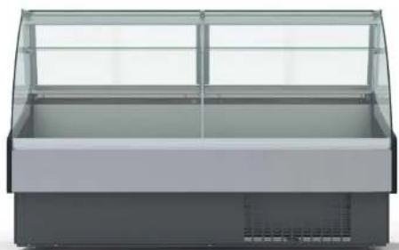
KFM-SC-S(R)

natural_image
Exterior view of a modern glass-and-steel display case (no visible text or symbols)KFM-SC-S(R)
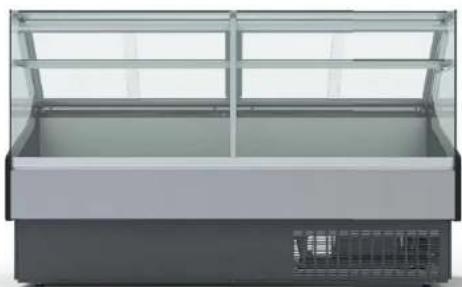
KFM-FG-S(R)(D)
natural_image
Exterior view of a modern refrigerated display case with glass panels and a closed lid (no visible text or symbols)KFM-FG-S(R)(D)
5.11 Drain inspection

Check for drain obstruction and correct position every month (Remotes only).

natural_image
Technical line drawing of a mechanical assembly with an inset showing a close-up of a component detail (no text or symbols present)5.12 Glass type conversion model

This operation must be performed by a qualified technician.

t distributor for specific manual to assist in conversion.
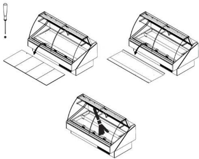
To access the evap pan:
- Remove protection grille.
- Unplug the evap pan.
- Relieve the screws and take the evap pan off.
- Clean with soft detergent or warm water.

natural_image
Technical line drawing of a mechanical assembly with tool and component details (no text or symbols)5.10 Fish Pans cleaning
This operation must be performed by a qualified technician.
All operations must be done with the unit disconnected.
To access the fish pan:
- Remove the front glass
- Empty the fish pan
- Clean the pan with adequate detergent and warm water
- Remove all particles from the drain

natural_image
Technical line drawing of a mechanical component or housing with internal structure and mounting bracket (no text or symbols)
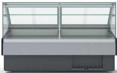
KFM-SF-S(R)
natural_image
Exterior view of a modern glass-and-steel display cabinet (no visible text or symbols)KFM-SF-S(R)


natural_image
Exterior view of a modern office building (no signage)5.8 Evaporator cleaning

This operation must be performed by a qualified technician.

operations must be done with the unit disconnected.
To access the evaporator:
- Open your unit
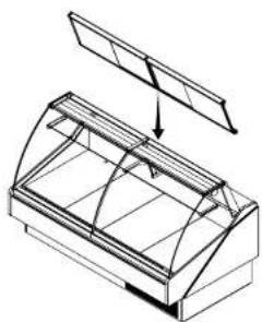
- Lift and remove exposition panels
- Use tool for the screws and clean
natural_image
Three technical line drawings of a curved glass terrarium or container with internal structure, shown from different angles (no text or symbols)5.9 Evap Pan cleaning

operation must be performed by a qualified technician.

operations must be done with the unit disconnected.

an be hot!

operation must be done weekly.
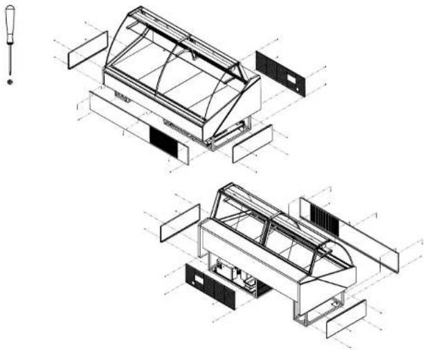
5.6 Panels and protection grille removal
natural_image
Technical line drawing of a modular device with internal components and exploded view (no text or symbols)KFM-SO-S(R)
This operation must be performed by a qualified technician. All operations must be done with the unit disconnected.
Condenser must be regularly cleaned (every month). Use a brush or vacuum it. To get to the condenser must remove frontal panel.
5.7 Condenser cleaning

natural_image
Technical line drawing of a mechanical device with a tool and internal components, shown from an exploded view (no text or symbols present)KFM-SO-S(R)
Implantation

Drain outlet

Electrical board

Refrigeration piping
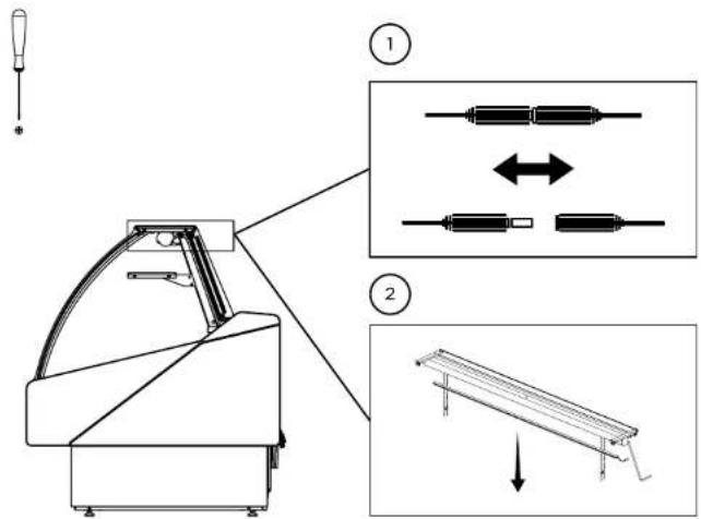
5.5 Light substitution
To replace lights follow the steps:

erations must be done with the unit disconnected.
- Disconnect the light
- Unscrew the light holder and remove the light
- Insert a new light in the same place of the old one, screw the holder connect it
- Screw the light and connect it
- Plug and turn on the light
← Front
KFM-CG-xx-S

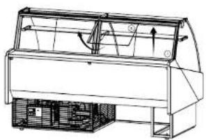
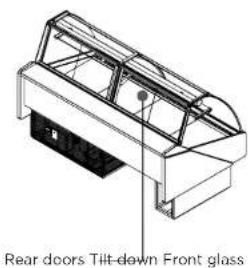
5.4. Back Sliding doors removal
Back sliding doors are easy to take off.
- Grab door push up and then tilt the bottom towards you.
To put the door back on, just reverse the previous step.
natural_image
Technical line drawing of a mechanical device with internal components and directional arrows (no text or symbols)KFM-CG-xx-R

Drain outlet

Electrical board

Refrigeration piping

Electrical wiring
For easier cleaning remove the front glass (instructions below).

natural_image
Two technical line drawings of a greenhouse structure with internal supports and ventilation ducts (no text or symbols)5.2 Interior cleaning
All operations must be done with the unit disconnected.
Clean surfaces (glass/metal/plastic) with soft detergent or warm water. Do not use abrasive cleanser.

natural_image
Isometric line drawing of a mechanical or architectural component with internal structure and no visible text or symbols5.3 Shelf removing
All operations must be done with the unit disconnected.
To remove or adjust shelves take care with light connections.
KFM-FG-xx-S
Main parameters
| Symbol | Code | Parameter | Models | UOM | Type | Min | Max | Def. |
| /S Probe display response MSYF | - | C | 0 | 15 | 0 | |||
| /S | Select °C or °F | MSYF | fl ag | C | 0 | 1 | 0 | |
| 0: °C | ||||||||
| 1: °F | ||||||||
| /A2 | Config guration of probe 2 (S2) | VF | - | C | 0 | 4 | 2 | |
| MS | - | C | 0 | 4 | 2 | |||
| 0: Probe absent | ||||||||
| 1: Product probe (display only) | ||||||||
| 2: Defrost probe | ||||||||
| 3: Condenser probe | ||||||||
| 4: Antifreeze probe | ||||||||
| /c1 | Calibration of probe 1 | MSYF | °C/°F | C | -20 | 20 | 0,0 | |
| SI | Temperature set point | MSYF | °C/°F | F | rl | r2 | 0,0 | |
| rd | Control delta | SYF | °C/°F | F | 0,1 | 20 | 2,0 | |
| c2 | Minimum compressor OFF time | SYF | min | C | 0 | 15 | 0 | |
| dl | Interval between defrosts | SYF | hours | F | 0 | 250 | 8 | |
| dPI | Maximum defrost duration, evaporator | SYF | min | F | 1 | 250 | 30 | |
5 Maintenance
5.1 Exterior cleaning

All operations must be done with the unit disconnected.
Clean surfaces (glass/metal/plastic) with soft detergents or warm water. Do not use abrasive cleanser.

natural_image
Isometric line drawing of a rectangular container with internal structure and hanging items (no text or symbols)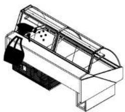
natural_image
Technical line drawing of a mechanical device or enclosure with internal components (no text or symbols)KFM-CG-xx-R

Drain outlet

Electrical board

Refrigeration piping
▲ Front
KFM-OF-xx-S
Signals on the display
The blinking status indicates a request for activatin that cannot be implemented until the end of the corresponding delay times.
| Icon | Function COMPRESS. FAN | ON compressor ON comp. OFF compressor request | blend | Startup | |
| fan ON | fan OFF | fan request | |||
| DEFROST | defrost in progress | defrost not required | defrost request | ||
| AUX | AUX | auxiliary output AUX active | auxiliary output anti AUX not active | sweat heater function active | |
| ALARM | delayed external alarm (before the expiry of the time A7) | no alarm present | alarms in normal operation (eg. high/low temp.) or alarm from ext. digital input immediate or delayed | ||
| CLOCK | at least one timed defrost has been set | no timed defrost is present | clock alarm | ON if Real-Time Clock present | |
| LIGHT | auxiliary output LIGHTACTIVE | auxiliary output LIGHT NOT ACTIVE | anti-sweat heater function active | ||
| SERVICE | no malfunction | malfunction (eg. EEPROM error or probe fault) | |||
| HACCP | HACCP | HACCP function | HACCP function enabled | HACCP alarm (HA and/or HF) not enabled | |
| CONTINUOUS CYCLE | enabled | not enabled | request | ||

Controller must be handled by a qualified technician.
Buttons on the keypad
Normal operation
Button|Press. the button alone Pressing together with other buttons
| Prgmute | · if pressed for more than 5 s accessed the menu for setting type "F" (frequent) parameters· in the event of alarm: silences the audible · if pressed for more than 5 s together alarm (buzzer) and with the AP/AUX button resets any alarm with manual reset | if pressed for more than 5 s together with the SET button, accesses the menu for setting the type "C" (configuration) or downloading the parameterspressed for more than 5 s together the UP/AUX button resets any alarm with manual reset | Start-up : if Automatic address pressed for assignment: more than if pressed for 1 s enters 5 s at start-up, the automatic serial starts the address assigning default procedure parameter setting | |
| aux | if pressed for more than 5 s, enables/disables the auxiliary output | if pressed for more than 5 s together with DOWN/DEF button, enables/disables the continuous cycle operation· if pressed for more than 5 s with SET button, starts the procedure for printing the reports (function available, with management to be implemented)· if pressed for more than 5 s together with PRG/MUTE button, resets any active alarm with manual reset | ||
| def▼ | if pressed for more than 5 s, enables/disables a manual defrost | if pressed for more than 5 s together with UP/AUX button, enables/disables the continuous cycle operation· if pressed for more than 5 s together with SET button, displays a submenu with the HACCP alarm parameters (HA, HAn, HF, HFrs) | ||
| Set | if pressed for more than 5 s, displays and/or set the set point | if pressed for more than 5 s together with PRG/MUTE button, accesses the menu for setting the type "C" parameters "C" (configuration) or downloading the parameters· if pressed for more than 5 s together with DOWN/DEF button, displays a submenu with the HACCP alarm parameters (HA, HAn, HF, HFrs)· if pressed for more than 5 s together with UP/AUX, starts the procedure for printing the report (function available, with management to be implemented) | ||
Relay outputs depending on the model
| EN 60730-1 UL 873 | ||||
| model | relay | 250 V~ | operating cycles cycles | 250 V~ operating |
| iRxxxx(E,A)(P,O,S,U,V,X,Y,Z)xxx | R2 (*) | 5(1)A 5 A resistive | 100000 | 6 LRA C 300 |
| iRxxxx(E,A)(N,R,C,B,A,M,L,T)xxx | R3 (*) | 5(1)A | 100000 | 5 A resistive 1FLA6 LRA C 300 |
| iRxxxx(E,A)(N,R,C,B,A,M,I,T)xxx | R1,R2 | 8 (4)A N.O. | 100000 | 8 A resistive 2FLA12 LRA |
| 6 (4)A N.C. | ||||
| iRxxxx(O,L,H)(N,R,C,B,A,M,L,T)xxx | R2,R3R4 (*) | 2 (2)A N.O./N.C. | C300 | |
| iRxxxx(E,A)(P,O,S,U,V,X,Y,Z)xxx | R1 | 12 (2)A N.O./N.C. | 100000 | 12 A resistive 5FLA30 LRA C300 |
| iRxxxx(O,L,H)(N,R,C,B,A,M,L,T)xxx | R1 (*) | |||
| insulation from very low voltage parts | reinforced | |||
| 6 mm clearance, 8 mm creepage | ||||
| 3750 V insulation | ||||
| insulation between the relay outputs independent | basic | |||
| 3 mm clearance, 4 mm creepage | ||||
| 1250 V insulation | ||||
SSR outputs | Max output voltage: 12 Vdc, Output resistance: 600 Ω, Max output current: 20 mA
(*) : Relay not suitable for fluorescent loads (neon lights, ...) that use starters (ballasts) with phase-shift
capacitors. Fluorescent lamps with electronic control devices or without phase-shift capacitors can be used, within the operation limits specified for each type of relay.
| Connessioni | Type of connection | Cross-section Max. current | |||
| Model Relay P. Supply Probes for wires from 12 A IRxxxxxx0xx screw | screw | screw | 0.5 a 2.5 mm 2 | removable screw | |
| IRxxxxx(E,A)x1xx | faston | faston | |||
| IRxxxxxx2xx | removable | removable | ble removable | ||
| IRxxxx(E,A)x3xx | faston | faston | |||
| IRxxxxx(E,A)x5xx | vertical | screw | vertical screw vertical screw | ||
the installer has to provide the correct dimensioning of the power supply and cable connection between the
disstruments and the loads. Depending on the model, the maximum current in the common terminals 1, 3 or 5 is 12.4. When using the controller at maximum operating temperature and full load use cables featuring a
maximum operating temperature of 105 °C at least

Controller must be handled by a qualified technician.
KFM-OF-xx-R

Drain outlet

Electrical board

Refrigeration piping
4.4. Electronic controller

Carel - IR33FOAHEO
TECHNICAL SPECIFICATIONS
| Model Voltage Power | |||
| Power supply | IRxxxxExxxx | 230 V~, 50/60 Hz 3 VA, 25 mA~max. | |
| IRxxxxAxxxx | 115V~, 50/60 Hz 3 VA, 50 mA~max. | ||
| IRxxxxHxxxx | 115 to 230 V~, 50/60 Hz 6 VA, 50 mA~max. | A~max. | |
| IRxxxxLxxxx | 12 to 24V~, 50/60 Hz, 12 to 30 Vdc | 3 VA, 300 mA~/mAdc max. | |
| IRxxxxDxxxx | 12V~, 50/60 Hz, 12 to 18 Vdc | Use only SELV power supply | |
| Insulation guaranteed by the power supply | IRxxxxExxxx | insulation in reference to very low voltage parts | reinforced6mm clearance, 8 mm creepage3750 V insulation |
| IRxxxxAxxxx | |||
| IRxxxxHxxxx | insulation from relay outputs | basic3mm clearance, 4 mm creepage1250V insulation | |
| IRxxxxLxxxx | insulation in reference to very low voltage parts | externally guaranteed by safety transformer (SELV power supply) | |
| IRxxxxDxxxx | insulation from relay outputs | reinforced6mm clearance, 8 mm creepage3750 V insulation | |
| Inputs | S1 (probe 1) | NTC (IRxxx0xxxxx) o NTC e PTC (IRxxx7xxxxx) | |
| S2 (probe 2) | NTC (IRxxx0xxxxx) o NTC e PTC (IRxxx7xxxxx) | ||
| DI 1 | free contact, contact resistance < 10 Ω, closing current 6 mA | ||
| S3 (probe 3) | NTC (IRxxx0xxxxx) o NTC e PTC (IRxxx7xxxxx) | ||
| DI 2 | free contact, contact resistance < 10 Ω, closing current 6 mA | ||
| S4 (probe 4) | NTC (IRxxx0xxxxx) o NTC e PTC (IRxxx7xxxxx) | ||
| Maximum distance of probes and digital inputs less than 10 m.Note: during installation keep the power and loads connection separate from probe cables,digital inputs; repeater display and supervisory system. | |||
| Probe type | Std. CAREL NTC | 10 kΩ at 25 °C, - 50T50 °C range | |
| measurement error: | 1 °C in the - 50T50 °C range | ||
| 3 °C in the - 50T90 °C range | |||
| NTC high temperature | 50 kΩ at 25 °C, - 40T150 °C range | ||
| measurement error: | 1.5 °C in the - 20T115 °C range | ||
| 4 °C in the - 20T115 °C range | |||
| PTC std. CAREL(specifi c model) | 985 Ω a 25 °C, range da - 50T150 °C | ||
| measurement error: | 2 °C in the - 50T50 °C range | ||
| 4 °C in the - 50T50 °C range | |||
Front
KFM-SC-xx-S
이 Z
9 | Terminal block
12 | Evaporator fan
20 | Light switch
21 Pilot light
22 | Switch
29 | Transformer
30 Led lighting
Discription
KFM-SC-xx-R

Drain outlet

Electrical board

Refrigeration piping

Electrical wiring
KFM-CG/FG-40/50/60/80/100/120-D


flowchart
graph TD
    A["①"] --> B["②"]
    B --> C["③"]
    C --> D["④"]
    D --> E["⑤"]
    E --> F["⑥"]
    F --> G["⑦"]
    G --> H["⑧"]
    H --> I["⑨"]
    I --> J["⑩"]
    J --> K["⑪"]
    K --> L["⑫"]
    L --> M["⑬"]
    M --> N["⑭"]
    N --> O["⑮"]
    O --> P["⑯"]
    P --> Q["⑰"]
    Q --> R["⑱"]
    R --> S["⑲"]
    S --> T["⑳"]
    T --> U["㉑"]
    U --> V["㉒"]
    V --> W["㉓"]
    W --> X["㉔"]
    X --> Y["㉕"]
    Y --> Z["㉖"]
KFM-SF-xx-S
6 Controller
7 Temperature probe
9 Terminal block
11 | Ground connection
12 Evaporator fan
20 | Light switch
21 Pilot light
22 | Switch
29 Transformer
30 | Led lighting
36 Fan anti-condensation
39 Solenoide valve
KFM-SF-xx-R

Drain outlet

Electrical board

Refrigeration piping

Electrical wiring
KFM-CG/FG-40/50/60/80/100/120-R
← Front

flowchart
graph TD
    A["①"] --> B["②"]
    B --> C["③"]
    C --> D["④"]
    D --> E["⑤"]
    E --> F["⑥"]
    F --> G["⑦"]
    G --> H["⑧"]
    H --> I["⑨"]
    I --> J["⑩"]
    J --> K["⑪"]
    K --> L["⑫"]
    L --> M["⑬"]
    M --> N["⑭"]
    N --> O["⑮"]
    O --> P["⑯"]
    P --> Q["⑰"]
    Q --> R["⑱"]
    R --> S["⑲"]
    S --> T["⑳"]
    T --> U["㉑"]
    U --> V["㉒"]
    V --> W["㉓"]
    W --> X["㉔"]
    X --> Y["㉕"]
    Y --> Z["㉖"]
    Z --> AA["㉗"]
    AA --> AB["㉘"]
    AB --> AC["㉙"]
    AC --> AD["㉚"]
    AD --> AE["㉛"]
    AE --> AF["㉜"]
    AF --> AG["㉝"]
KFM-SO-xx-S
1 | Compressor
2 Overload
3 | Relay
4 | Start capacitor
5 | Condenser fan
6 | Controller
7 | Temperature probe
8 | Earth two pin plug
9 | Terminal block
11 | Ground connection
12 Evaporator fan
13 | Compressor relay
20 | Light switch
21 | Pilot light
22 | Switch
29 | Transformer
30 | Led lighting
36 | Fan anti-condensation
31 | Socket
41 | Evaporative condensate pan
Discription
KFM-SO-xx-R
KFM series intended for deli, meat and fish are type 1 equipment - 75°F/55%RH. Temperature of deli, meat and fish cases is set for 32°F.
The decks have a 31 lb/ft 2 loading limit.
Glass shelves are for non refrigerated products only and have a 5,5 lb/ff loading limit.
| Model | Dimensions (LxDxH in inches) | Service dimensions (LxDxH in inches) | Volume (ft3) |
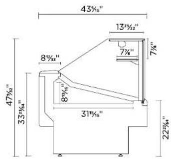
| KFM-CG/SC-40-S(R) | 4038" × 4918" × 6118" | 4038" × 4918" × 6218" | 6,0/2,5 |
| KFM-CG/SC-50-S(R) | 5218" × 4918" × 6118" | 5218" × 4918" × 6218" | 8,0/3,4 |
| KFM-CG/SC-60-S(R) | 6018" × 4918" × 6118" | 6018" × 4918" × 6218" | 9,3/4,0 |
| KFM-CG/SC-80-S(R) | 7718" × 4918" × 6118" | 7718" × 4918" × 6218" | 12,1/5,1 |
| KFM-CG-100-S(R) | 10118" × 4918" × 6118" | 10118" × 4918" × 6218" | 16,0 |
| KFM-CG-120-S(R) | 11618" × 4918" × 6118" | 11618" × 4918" × 6218" | 18,6 |
| KFM-FG/SF-40-S(R) | 4038" × 4412" × 6118" | 4038" × 4412" × 6818" | 6,0/2,5 |
| KFM-FG/SF-50-S(R) | 5218" × 4412" × 6118" | 5218" × 4412" × 6818" | 8,0/3,4 |
| KFM-FG/SF-60-S(R) | 6018" × 4412" × 6118" | 6018" × 4412" × 6818" | 9,3/4,0 |
| KFM-FG/SF-80-S(R) | 7718" × 4412" × 6118" | 7718" × 4412" × 6818" | 12,1/5,1 |
| KFM-FG-100-S(R) | 10118" × 4412" × 6118" | 10118" × 4412" × 6818" | 16,0 |
| KFM-FG-120-S(R) | 11618" × 4412" × 6118" | 11618" × 4412" × 6818" | 18,6 |
| KFM-OF/SO-40-S(R) | 4038" × 3418" × 6118" | 4038" × 4918" × 6118" | 6,0/2,5 |
| KFM-OF/SO-50-S(R) | 5238" × 3418" × 6118" | 5238" × 3418" × 6118" | 8,0/3,4 |
| KFM-OF/SO-60-S(R) | 6018" × 3418" × 6118" | 6018" × 3418" × 6118" | 9,3/4,0 |
| KFM-OF/SO-80-S(R) | 7718" × 3418" × 6118" | 7718" × 3418" × 6118" | 12,1/5,1 |
| KFM-OF-100-S(R) | 10118" × 3418" × 6118" | 10118" × 3418" × 6118" | 16,0 |
| KFM-OF-120-S(R) | 11618" × 3418" × 6118" | 11618" × 3418" × 6118" | 18,6 |
KFM-CG/FG-100/120-S

flowchart
graph TD
    A["Motor ①"] --> B["Switch"]
    B --> C["Motor ②"]
    C --> D["Motor ③"]
    D --> E["Motor ④"]
    E --> F["Motor ⑤"]
    F --> G["Motor ⑥"]
    G --> H["Motor ⑦"]
    H --> I["Motor ⑧"]
    I --> J["Motor ⑨"]
    J --> K["Motor ⑩"]
    K --> L["Motor ⑪"]
    L --> M["Motor ⑫"]
    M --> N["Motor ⑬"]
    N --> O["Motor ⑭"]
    O --> P["Motor ⑮"]
    P --> Q["Motor ⑯"]
    Q --> R["Motor ⑰"]
    R --> S["Motor ⑱"]
    S --> T["Motor ⑲"]
    T --> U["Motor ⑳"]
    U --> V["Motor ㉑"]
    V --> W["Motor ㉒"]
    W --> X["Motor ㉓"]
    X --> Y["Motor ㉔"]
    Y --> Z["Motor ㉕"]
    Z --> AA["Motor ㉖"]
    AA --> AB["Motor ㉗"]
    AB --> AC["Motor ㉘"]
    AC --> AD["Motor ㉙"]
    AD --> AE["Motor ㉚"]
    AE --> AF["Motor ㉛"]
    AF --> AG["Motor ㉜"]
    AG --> AH["Motor ㉝"]
1 | Compressor
2 | Overload
3 | Relay
4 | Start capacitor
5 | Condenser fan
6 | Controller
7 | Temperature probe
8 | Earth two pin plug
9 | Terminal block
11 | Ground connection
12 Evaporator fan
13 | Compressor relay
20 | Light switch
21 | Pilot light
22 | Switch
29 | Transformer
30 | Led lighting
36 | Fan anti-condensation
31 | Socket
41 | Evaporative condensate pan
2 Getting started with your KFM series
2.1 Location
To your new equipment perform well please respect the following warnings:
This is type 1 equipment, intended to work with 75ircF / 55% RH .
This equipment is intended for maintaining temperature only.
Be sure products are not ambient temperature (must be cold)
This equipment must be located in an indoor environment.
Check for airdrafts and avoid them.
At movement from ac units shouldn't be directed to the equipment.
The equipment must not be directly or indirectly exposed to the sun.
Check for rejected heat from another refrigeration units and avoid that.
Place the equipment in a levelled floor.
Do not obstruct the air way in front of the condenser.
Make sure there is a drain preparation (remotes and fish display cases only).
Models to be positioned against a wall keep a safe distance of 2 3/8 .
After servicing always close the doors.
Make sure you have a suitable electrical installation.
This equipment should be handled by a qualified technician.
2.2 Uncrating
All operations must be done carefully.
All plastic protective films must be removed before using the equipment for the first time.
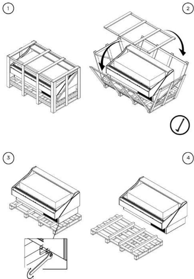
4.3. Electrical diagrams
KFM-CG/FG-40/50/60/80-S

flowchart
graph TD
    A["1"] --> B["2"]
    B --> C["3"]
    C --> D["4"]
    D --> E["5"]
    E --> F["6"]
    F --> G["7"]
    G --> H["8"]
    H --> I["9"]
    I --> J["10"]
    J --> K["11"]
    K --> L["12"]
    L --> M["13"]
    M --> N["14"]
    N --> O["15"]
    O --> P["16"]
    P --> Q["17"]
    Q --> R["18"]
    R --> S["19"]
    S --> T["20"]
    T --> U["21"]
    U --> V["22"]
    V --> W["23"]
    W --> X["24"]
    X --> Y["25"]
    Y --> Z["26"]
    Z --> AA["27"]
    AA --> AB["28"]
    AB --> AC["29"]
    AC --> AD["30"]
    AD --> AE["31"]
    AE --> AF["32"]
    AF --> AG["33"]
    AG --> AH["34"]
    AH --> AI["35"]
    AI --> AJ["36"]
    AJ --> AK["37"]
    AK --> AL["38"]
    AL --> AM["39"]
    AM --> AN["40"]
4.2. Electrical service receptacles (optional)

Service receptacles are not intended nor suitable for large motors or other I appliances. Only for scales and lighted displays.

erations must be done with the unit disconnected
Receptacle ampacity
| Type | Max. amps |
| GFCI | 2 |
2.2.1 Front and sides assemblies

2x - VID24M01095


2x - VID07003000 1x - PRT01201190

1x - BRA09M02000

2x - PAR00802002
DIN912 M5x12

2x - ANL00101006
DIN 127

2x- ANL00501006
DIN 9021

1x - PRN00101002
DIN 916
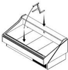
1x - APO01101000 1x - PAR00902001
DIN7380 M5x12

1x - PAR00902004
DIN7380 M4x10

6 x - CMS00101000

10 x - PAR11101001 1x - GAM13M01200


4x - POR19M01100

1x - PAR01002013 1x - PRT01301190


2x - SUP17M01020
1
natural_image
Isometric line drawing of a rectangular container with internal structure and directional arrows (no text or symbols)2

natural_image
Isometric line drawing of a rectangular container with internal structures and two directional arrows indicating movement (no text or symbols)3

natural_image
Isometric line drawing of a 3D container with internal structure and support beams (no text or symbols)4

natural_image
Technical line drawing of a mechanical assembly with no visible text or symbols5

natural_image
Isometric line drawing of a 3D architectural structure with curved and rectangular panels, no text or symbols present6

natural_image
Technical line drawing of a mechanical component with internal structure and mounting bracket (no text or symbols)115V/60Hz/1 phase
| Model | Compressor F.L.A./L.R.A. | Lights | Fans | Evap pan | Anti condensation system | Total amps (self contained) |
| EVP CND | FANS | |||||
| KFM-SO-60-S | 9,6/49 | 0,30 0,45 | 13,68 | |||
| KFM-SO-80-S | 8,9/47 | 0,30 0,90 | 13,43 | |||
| KFM-SO-100-S | 16/64 | 0,40 0,90 | 20,63 | |||
| KFM-SO-120-S | 16/64 | 0,50 0,90 | 20,73 |
The data regards to standard options only.
| Model | Total amps (remotes only) | Model | Total amps (remotes only) |
| KFM-CG/FG-40-R | 0,5 | KFM-OF-60-R | 0,3 |
| KFM-CG/FG-50-R | 0,51 | KFM-OF-80-R | 0,3 |
| KFM-CG/FG-60-R | 0,63 | KFM-OF-100-R | 0,4 |
| KFM-CG/FG-80-R | 0,78 | KFM-OF-120-R | 0,5 |
| KFM-CG/FG-100-R | 0,91 | KFM-SO-40-R | 0,2 |
| KFM-CG/FG-120-R | 1,16 | KFM-SO-50-R | 0,2 |
| KFM-SC/SF-40-R | 0,5 | KFM-SO-60-R | 0,3 |
| KFM-SC/SF-50-R | 0,51 | KFM-SO-80-R | 0,3 |
| KFM-SC/SF-60-R | 0,63 | KFM-SO-100-R | 0,4 |
| KFM-SC/SF-80-R | 0,78 | KFM-SO-120-R | 0,5 |
| KFM-SC/SF-100-R | 0,91 | ||
| KFM-SC/SF-120-R | 1,16 | ||
| KFM-OF-40-R | 0,2 | ||
| KFM-OF-50-R | 0,2 |
4 Electrical
4.1. Electrical specifications data

Electrical data can be found on the marking plate.
Standard equipment includes led lighting and anti condensation system.
115V/60Hz/1 phase
| Model | Compressor F.L.A./L.R.A. | Lights | Fans | Evap pan | Anti condensation system | Total amps (self contained) | |
| EVP CND | FANS | ||||||
| KFM-CG/FG-40-S | 8,4/43 | 0,04 | 0,20 | 0,45 | 3,33 | 0,26 | 12,68 |
| KFM-CG/FG-50-S | 9,6/49 | 0,05 | 0,20 | 0,45 | 3,33 | 0,26 | 13,89 |
| KFM-CG/FG-60-S | 9,6/49 | 0,07 | 0,30 | 0,45 | 3,33 | 0,26 | 14,01 |
| KFM-CG/FG-80-S | 8,9/47 | 0,09 | 0,30 | 0,90 | 3,33 | 0,39 | 13,91 |
| KFM-CG/FG-100-S | 16/64 | 0,12 | 0,40 | 0,90 | 3,33 | 0,39 | 21,14 |
| KFM-CG/FG-120-S | 16/64 | 0,14 | 0,50 | 0,90 | 3,33 | 0,52 | 21,39 |
| KFM-SC/SF-40-S | 8,4/43 | 0,04 | 0,20 | 0,45 | 0,26 | 12,68 | |
| KFM-SC/SF-50-S | 9,6/49 | 0,05 | 0,20 | 0,45 | 0,26 | 13,89 | |
| KFM-SC/SF-60-S | 9,6/49 | 0,07 | 0,30 | 0,45 | 0,26 | 14,01 | |
| KFM-SC/SF-80-S | 8,9/47 | 0,09 | 0,30 | 0,90 | 0,39 | 13,91 | |
| KFM-SC/SF-100-S | 16/64 | 0,12 | 0,40 | 0,90 | 0,39 | 21,14 | |
| KFM-SC/SF-120-S | 16/64 | 0,14 | 0,50 | 0,90 | 0,52 | 21,39 | |
| KFM-OF-40-S | 8,4/43 | 0,20 | 0,45 | 3,33 | 12,38 | ||
| KFM-OF-50-S | 9,6/49 | 0,20 | 0,45 | 3,33 | 13,58 | ||
| KFM-OF-60-S | 9,6/49 | 0,30 | 0,45 | 3,33 | 13,68 | ||
| KFM-OF-80-S | 8,9/47 | 0,30 | 0,90 | 3,33 | 13,43 | ||
| KFM-OF-100-S | 16/64 | 0,40 | 0,90 | 3,33 | 20,63 | ||
| KFM-OF-120-S | 16/64 | 0,50 | 0,90 | 3,33 | 20,73 | ||
| KFM-SO-40-S | 8,4/43 | 0,20 | 0,45 | 12,38 | |||
| KFM-SO-50-S | 9,6/49 | 0,20 | 0,45 | 13,58 | |||
The data regards to standard options only.
7
natural_image
Isometric line drawing of a greenhouse structure with a sloped roof and a diagonal panel above it (no text or symbols)8

natural_image
Isometric line drawing of a curved, dome-shaped structure with internal grid lines (no text or symbols)2.3 Check for damage
At the end of production HYDRA KOOL products are carefully inspected. No damaged units are sent out.
HYDRA KOOL doesn't take responsibility for damage between factory and client.
Possible damage on the unit must be checked to file a claim near the transportation company.
The unit must be checked in the following points:
Exterior panels
Doors
Shelves
Glasses
Paint job
Door handles
Base structure
Fish pans
2.4 Control panel and main features
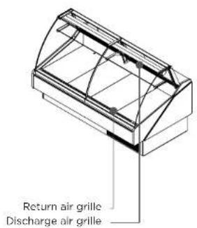
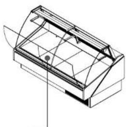
The pictures below, shows the main features and all necessary controls.

Remote control panel (KFM-CG/FG/OF/SC/SF/SO)
All self contained KFM series use the following equipment: capillary tube, finned coil ventilated systems (condenser/evaporator), hermetic compressor, electrical water evaporation system.
| Model | Circuit pressure (psig) | Refrigerant and charge (OZ) | Defrost | |
| High side | Low side | |||
| KFM-CG/SC/FG/SF/OF/SO-40-S | 331 | 174 | R 404A 14,10 | Automatic 3/day |
| KFM-CG/SC/FG/SF/OF/SO-50-S | 331 | 174 | R 404A 19,40 | Automatic 3/day |
| KFM-CG/SC/FG/SF/OF/SO-60-S | 331 | 174 | R 404A 19,40 | Automatic 3/day |
| KFM-CG/SC/FG/SF/OF/SO-80-S | 331 | 174 | R 404A 25,39 | Automatic 3/day |
| KFM-CG/SC/FG/SF/OF/SO-100-S | 331 | 174 | R 404A 37,74 | Automatic 3/day |
| KFM-CG/SC/SF/FG/OF/SO-120-S | 331 | 174 | R 404A 42,33 | Automatic 3/day |
3.2 Refrigeration loads (remotes only)
Installation of remote equipment must be done by a qualified technician.
| Model | BTU*/h | Expansion valve type | |
| KFM-CG/SC/FG/SF/OF/SO-40-R | 2548 | TS2 | 00 |
| KFM-CG/SC/FG/SF/OF/SO-50-R | 3015 | TS2 | 00 |
| KFM-CG/SC/FG/SF/OF/SO-60-R | 3159 | TS2 | 00 |
| KFM-CG/SC/FG/SF/OF/SO-80-R | 4345 | TS2 | 00 |
| KFM-CG/SC/FG/SF/OF/SO-100-R | 5112 | TS2 | 00 |
| KFM-CG/SC/FG/SF/OF/SO-120-R | 5472 | TS2 | 00 |
*values presented are indicative for 14°F evap, and 90°F ambient.


Dry control panel (KFM-CG/FG/OF)
natural_image
Isometric line drawing of a curved, dome-shaped container or enclosure with internal grid lines (no text or symbols)2.5 Check serial, model numbers and requested options
Before start your equipment, check the serial number, model numbers and requested options.
This inspection should be made visually in the following items:

Maintain doors closed after servicing.
9 - If any problem encountered, see troubleshooting or call a qualified technician!
3 Refrigeration
3.1 Self contained refrigeration equipment and defrost
The refrigeration equipment it's laid out in the base of the equipment.

natural_image
Technical line drawing of a mechanical or architectural component with internal structure and no visible text or symbols6 - Check air movement in the anti condensation system.

natural_image
Isometric line drawing of a mechanical housing or enclosure with internal compartments and a handle (no text or symbols)7 - Before loading, leave the equipment working for about 2h.
8 - Load your KFM-Series.
Loading must be done respecting loading limits and weight per square foot mentioned in page xx. This equipment is intended for maintaining temperature, be sure the products are cold, and not ambient temperature.
After loading check for any obstruction in the discharge and return air grilles.
Self contained numbers

natural_image
Close-up of a dark, rectangular metallic object with a small label on the left (no visible text or symbols)
Remote numbers

natural_image
Close-up of a metallic shelf with a small label (no visible text or symbols)
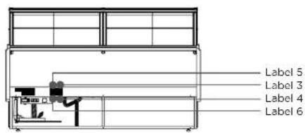
2.6 Warning/Caution labels
Before starting, HYDRA KOOL products have caution and warning labels to be respected.
Self contained labels

Remote labels
Dry labels

2.10 Plugging and start
To start your equipment follow the steps:
1 - Check for page with parameters inside the manual.
2 - After uncrating and placed the equipment respecting all warnings set in 2.1 chapter, and all switches are set to off position, connect the equipment.
Make sure you have the correct outlet!

Nema-5-15P Nema-5-20P

3 - Check lights, using button referenced on chapter 2.4. If not working consult the maintenance chapter.
4 - Turn ON power button referenced in 2.4 chapter.
Noise will be heard when compressor starts! If compressor doesn't start, call a technician!
5 - Open the door and check for air movement in the discharge air grille.

natural_image
Technical line drawing of a 3D mechanical component with internal grid structure (no text or symbols)

natural_image
Technical line drawing of a multi-tiered industrial machine or storage unit (no text or symbols visible)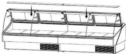
natural_image
Technical line drawing of a multi-level industrial or storage unit with ventilation grilles and mounting brackets (no text or symbols)
natural_image
Technical line drawing of a multi-level storage or rack system with mounting brackets and ventilation grilles (no text or symbols)
natural_image
Technical line drawing of a multi-tiered storage or rack system with no visible text or symbolsSelf contained labels

Remote labels

Dry labels

Self contained, Remote, Dry and Seafood labels (evaporator)

Label 1 Label 2
CAUTION
MOVING PARTS. DO NOT OPERATE UNIT WITH (PART) REMOVED
Label 3 Label 4
-NOTE- THIS A TYPE 1 CASE AND IS DESIGNED TO OPERATE AT THE FOLLOWING STORE CONDITIONS THAT DOES NOT EXCEED 75 F AND 55% R.H.
Label 5 Label 6
-NOTE-
THIS EQUIPMENT IS INTENDED FOR THE STORAGE AND DISPLAY OF PACKAGED FOOD PRODUCTS ONLY
ATTENTION
PIÈCES MOBILES. NE FAIRE PAS FONCTIONNER AVEC DES PIÈCES ENLEVER
-NOTE-
CETTE VITRINE TYPE 1 EST CONÇUE POUR FONCTIONNER SELON LES CONDITIONS DU MAGASIN ET NE DOIT DÉPASSER 75 F AND 55% R.H.
-NOTE-
CET EQUIPEMENT EST PREVU UNIQUEMENT POUR LE STOCKAGE ET EXPOSITION DE PRODUITS ALIMENTAIRES EMBALLER

natural_image
Line drawing of a multi-level appliance or storage unit with heat sinks (no text or symbols)

1x - DIN7380 M5x50


1x - DIN7380 M5x10


1x - DIN912 M4x12

HOT PARTS. DO NOT OPERATE UNIT WITH (PART) REMOVED
Label 13 Label 14
CAUTION
HAZARDOUS MOVING PARTS. DO NOT OPERATE UNIT WITH DECK PANS
ATTENTION
DEBRANCHER TOUTE COURANT. IL PEUT AVOIR PLUS D'UN INTERRUPTEUR
ATTENTION
RISQUE DE CHOC ELECTRIQUE. AVANT TOUT TRAVAIL COUPER LE COURANT
ATTENTION
PIÈCES BRULANTES. NE FAIRE PAS FONCTIONNER AVEC LES PIÈCES ENLEVER
ATTENTION
PIÈCES MOBILES DANGEREUSES. NE FAIRE PAS FONCTIONNER AVEC DES PIÈCES ENLEVER
Label 15
Warning
- This appliance requires a properly grounded dedicated circuit using a NEMA rated wall receptacle do not remove the grounding prong on the plug or the risk of an injury due to shock from the ungrounded electrical service may occur.
- This product can expose an individual to chemicals that have been identified by the state of California to possibly be dangerous leading to various diseases birth defects or other human reproductive system harm. For more information go to www.p65warnings.ca.gov.
2.7 Check your electrical installation

This equipment is intended to be connected to an outlet with 115V/60Hz/1 phase.

Nema-5-15P

Nema-5-20P
2.8 Electrical, drain and refrigeration connections (remotes only)

ation and service must be performed by a qualified technician.

natural_image
Architectural floor plan showing room layouts and equipment placement (no text or labels)Prepare a drain installation
All electrical connections must be done from the electrical board Equipments for remote installation come with nitrogen under pressure and an easy prep kit (tubing connections needed only) for installation.


natural_image
Technical line drawing of a mechanical device with a fan and internal components (no text or symbols)
2X - FIT00000427 (91%")

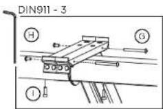
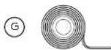
2.9 Joining
For joining follow the steps described.

natural_image
Line drawing of a multi-level display cabinet with heat sinks (no text or symbols)
3x - PAR00601013 DIN933 M6x80

4x - PAR00801102 DIN912 8.8

2x - PAR00601007 DIN933 M6x20

4x - ANL00101006 DIN 127-B

14x- ANL00501006 DIN9021 M6

2x - BRA09M02000 VA 71

5x - PRC00101006 DIN934 M6
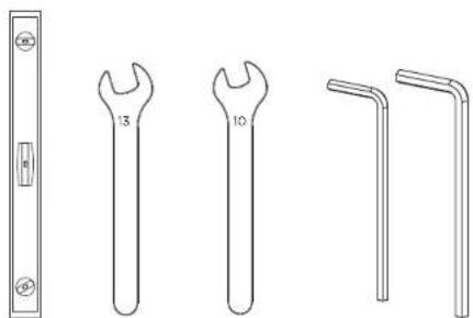
2X FIT00000202 A100 04 (153%)
natural_image
Technical line drawings of wrenches and bent rods (no text or symbols)1x
1x DIN911 - 3/4

natural_image
Line drawing of a modern refrigerated display case with a cooling fan and ventilation grilles (no text or symbols)2x KFM-CG

natural_image
Technical line drawing of a mechanical bracket assembly (no text or symbols)KIT0005U02000
- HYDRA KOOL
- | General information 5
- Case description 5
- Getting started with your KFM series 25
- Warranty
- General information
- KFM CG 40 S
- AAA BB CC D
- Troubleshooting/Service
- Drain inspection
- Glass type conversion model
- Evaporator cleaning
- Evap Pan cleaning
- Back Sliding doors removal
- Interior cleaning
- Shelf removing
- Maintenance
- Exterior cleaning
- Signals on the display
- Getting started with your KFM series
- Uncrating
- Electrical service receptacles (optional)
- Front and sides assemblies
- Electrical
- Check for damage
- Control panel and main features
- Refrigeration loads (remotes only)
- Check serial, model numbers and requested options
- Refrigeration
- Warning/Caution labels
- Plugging and start
- CAUTION
- -NOTE-
- ATTENTION
- Label 15
- Warning
- Check your electrical installation
- Electrical, drain and refrigeration connections (remotes only)
Brand : Hydra Kool
Model : KFM-SC-50-S
Category : Refrigerator