
VMB1TCW - Thermostat Velbus - Free user manual and instructions
Find the device manual for free VMB1TCW Velbus in PDF.


| Product Type | Thermostat |
| Brand | Velbus |
| Model | VMB1TCW |
| Dimensions (W x H x D) | 120 mm x 80 mm x 30 mm |
| Weight | 150 g |
| Power Supply | 24 V DC (from Velbus bus) |
| Power Consumption | < 0.5 W |
| Temperature Measurement Range | 0°C to 40°C |
| Accuracy | ±0.5°C |
| Control Type | Digital, programmable |
| Compatible Systems | Velbus home automation |
| Main Functions | Temperature measurement, heating/cooling control, scheduling, remote control via Velbus |
| Interface | Touch buttons, LED indicators |
| Installation | Wall-mounted, wired connection to Velbus bus |
| Protection Class | IP20 |
| Operating Temperature | 0°C to 40°C |
| Storage Temperature | -10°C to 50°C |
| Maintenance | Clean with a soft, dry cloth. Do not use water or solvents. |
| Safety | Low voltage (SELV), no user-serviceable parts inside. |
| Spare Parts & Repairability | Non-user-serviceable. Contact Velbus support for repairs. |
| Additional Information | Part of the Velbus home automation system; requires Velbus bus and controller. |
Frequently Asked Questions - VMB1TCW Velbus
User questions about VMB1TCW Velbus
0 question about this device. Answer the ones you know or ask your own.
Ask a new question about this device
Download the instructions for your Thermostat in PDF format for free! Find your manual VMB1TCW - Velbus and take your electronic device back in hand. On this page are published all the documents necessary for the use of your device. VMB1TCW by Velbus.
USER MANUAL VMB1TCW Velbus
natural_image
Modern interior design with three white shelves displaying interior views and a stylized tree in the background (no text or symbols on main objects)VMB1TC
Temperature control module for the Velbus system

CONTENTS
CONTENTS 2
DESCRIPTION....4
CHARACTERISTICS......4
VELBUS CHARACTERISTICS 6
Connecting the temperature controller VMB1TC 12
Connecting the temperature sensor VMB1TS....12
Relay cabinet wiring 13
Terminator 14
Addressing....14
Allocate the relay channels....14
Allocate a relay channel to control valve 1....15
Allocate a relay channel to control valve 2....16
Allocate a relay channel to control valve 3....17
Allocate a relay channel to control the fan ....18
Allocate a relay channel for day mode of the boiler 19
Allocate a relay channel for the circulation pump....20
SCREEN INDICATIONS 21
LED INDICATION 21
BUTTON FUNCTIONS 22
MENU STRUCTURE....23
Direct access menu....23
Extended menu....24
CONFIGURATION OF THE TEMPERATURE CONTROLLER....26
Choice of language....26
Temperature read-out (°Celsius or °Fahrenheit)......27
Master clock....28
Global alarm 29
Battery backup....30
Addressing....32
Assign an action to the wake-up time....33
Assign an action to the go-to-bed time....36
Searching for temperature sensors....38
Setting the clock 39
Setting the alarm clock 41
Disabling the alarm clock function....43
Setting the display contrast ....44
Setting the backlight of the display....45
CONFIGURATION OF THE TEMPERATURE SENSORS 47
Assign sensor names 47
Defining zones 49
Change the default zone names....51
Heating or cooling mode....53
Lock or unlock local mode setting 54
Default duration of temporary mode (default sleep time)....55
Low temperature alarm....56
High temperature alarm....57
Anti-freeze temperature....58
Heating limit....59
Minimum cooling temperature 60
Maximum cooling temperature 61
Hysteresis temperature 62
Temperature difference 63
Difference sensor....64
Protecting the circulation pump 65
Protecting the valves 66
Calibrating the sensor....67
VERIFY SOFTWARE VERSION....68
PIN CODE PROTECT THE EXTENDED MENU....69
OPERATING THE TEMPERATURE SENSOR VMB1TS 71
Anti-freeze, night, day or comfort mode indication 71
Cooling or heating mode indication 71
Air-conditioner or heater active indication 71
Operation....72
Select room or zone 73
Recall and change the desired temperature 74
Temporarily switching between comfort, day, night or anti-freeze mode....74
Setting the sleep time (temporary mode) 76
Holiday setting....77
Summer setting....78
Setting the comfort, day and night temperature 79
STATISTICS 81
Requesting statistics....81
Reset statistics....83
PROGRAM INSTRUCTIONS LOCATION 84
PROGRAMMING 86
Overview program instruction....88
Entering a new program instruction....89
Changing a program instruction 91
Removing a program instruction....93
DIFFERENTIAL THERMOSTAT....94
The passage automatically 3° cooler than the office....95
Passive cooling of a bedroom 99
DESCRIPTION
The temperature controller (VMB1TC) forms in combination with one or more temperature sensors (VMB1TS) and relay modules (VMB1RY or VMB4RY) a programmable thermostat to control a heating or cooling installation.
The different sensors can be adjusted, operated and programmed from one location by using this temperature controller. Multiple controllers at multiple locations are possible.
It is also possible to define zones to group the sensors.
CHARACTERISTICS
Forms a programmable thermostat together with a Velbus temperature sensor and relay modules
Ideal to control the heating or air-conditioning of your residence
Can control a maximum of 32 temperature sensors (VMB1TS)
Up to 7 zones can be defined
Each sensor/zone can be placed in automatic mode (to follow the program), temporary mode (the program is suspended for a certain time) or manual mode (the program is disabled for an undefined time period)
Configurable both locally or via PC (using the serial or USB interface in combination with the Velbus link software)
All settings are retained in case of a power cut
Relay control through the Velbus e.g. for alarms
Possibility to set up a differential thermostat using two sensors
LED indication
- When the heater or cooler is active
- When in temporary mode (sleep timer), a LED is flashing
- During high or low temperature alarm, a LED will flash
- When power supply is detected
- When receiving or transmitting data over the Velbus
LCD:
- 2 lines of 16 characters to indicate the name of the selected sensor/zone, the selected mode (comfort, day or night, anti-freeze), the temperature and the time
- On screen indication of manual mode, temporary mode, duration of temporary mode (sleep time), key guard and cooling function
- Adjustable white backlight
- Possibility to adjust backlight automatically every day (2 times)
- Adjustable contrast
Clock
• Built-in clock with day indication
- Adjusting one clock synchronizes all other clocks on the Velbus system.
- Possibility to use one clock as reference for all other clocks in the system
- Wake-up function: 2 moments (wake-up time and sleep time) can be set
Local control
- Scroll through the different sensors with one button.
- Direct access to change the mode (comfort, day, night or anti-freeze) and the desired temperature.
-
A short press on the menu button will open the short configuration menu:
-
set the comfort, day or night temperature
- switch the alarm clock on or off, configure the wake-up and sleep times)
- adjust the clock
- configure the duration of the sleep mode (sleep time)
- Press and hold the menu button (4s) to enter the extended configuration menu:
- enter or change program instructions
- configure the sensors (cooling/heating, lock/unlock control, sleep time, low and high temperature alarm, anti-freeze temperature, upper heat temperature, lower and upper cool temperature, hysteresis, temperature difference, unblock pump/valve, zone number, difference sensor, sensor calibration and sensor name)
- select language, read out (°C or °F), reference clock (on/off), alarm time (global/local), emergency power supply (on/off) or change PIN
- set the address (254 possible), link the alarm output or search for all sensors present on the Velbus
- change the contrast and the backlight of the display
- recall statistics (minimum, maximum temperature and duration of heating/cooling)
- The extended configuration menu can be secured by a PIN.
- The menu is closed automatically after ± 1 minute of inactivity.
Programming
- A program instruction can switch a sensor between comfort, day, night or anti-freeze mode at a certain time.
- Possibility to enter program instructions that are applicable for all zones or for all sensors in a defined zone.
- Up to 31 program instructions can be saved per sensor or zone.
- Program types:
• day programs: every Monday, Tuesday, Wednesday, Thursday, Friday, Saturday or Sunday - working day programs: from Monday up to and including Friday or Saturday
- weekend programs: every Saturday and Sunday
• week programs: every day - Wake-up time and sleep time can be used inside program instructions.
Power supply
- Required power supply: 12 to 18VDC
• Consumption backlight off: 25mA
• Maximum consumption (LEDs activated, backlight max.): 50mA - Battery emergency power supply: 3V Lithium battery (CR2032 included)
- Consumption emergency power supply not active: 0.5µA
- Consumption emergency power supply activated: 200µA
- Display warning when battery needs replacement
Dimensions
- Module (L x B x H): 66 x 44 x 40mm
-
Dimensions including cover plate (L x B x H): 118 x 80 x 40mm
• Cover plate not included -
2-wire communication for Velbus data and 2 wires for power supply
• data transmission: 16.6 Kbit/s - Serial data protocol: CAN (Controller Area Network)
- Short circuit proof (towards negative or positive pole of the power supply)
- LED indication when receiving or transmitting data over the Velbus
- bus error indication: 2 short flashes of the LEDs
- auto recovering after 25 seconds when a bus error occurs
The temperature controller module can be given a designation with a maximum of 16 characters.
The temperature controller module can transmit following messages:
- the current time
• the output status of the alarm clock - the controller status
- the controller type (including software version)
- the controller name
• the communication error counter
• a program instruction - the memory content
The temperature controller module can transmit following instructions:
- Request the:
o module type (to search for sensors)
o current time - memory content
o sensor name - sensor set-up
o sensor status
o sensor temperature
o sensor time statistics
o program instruction - Set the:
o program storage location - program availability
- program instruction
o sensor zone - desired temperature for a sensor
o sensor comfort temperature for heating
o sensor day temperature for heating
o sensor night temperature for heating
o sensor anti-freeze temperature for heating
o upper heat temperature
o temperature difference for fast heating/cooling or differential thermostat
o hysteresis temperature for a sensor
o sensor comfort temperature for cooling
o sensor day temperature for cooling
o sensor night temperature for cooling
o lower limit of the cooling preset range
o upper limit of the cooling preset range
o sensor calibration factor - low temperature alarm of a sensor
o high temperature alarm of a sensor
- put the sensor in:
o heating mode
o cooling mode
- comfort mode
- in day mode
- night mode
- anti-freeze mode
- synchronize the alarm clock time
- lock the local sensor controls
- unlock the local sensor controls
-
standard duration for temporary mode (sleep time) for a sensor
-
reset the minimum and/or maximum temperature
- reset the time statistics of a sensor
- set or reset the de-blocking of the valve and/or circulation pump
• write to sensor memory - The address of the linked sensor to set up a differential thermostat
The temperature controller module can receive following messages:
- the sensor type
- the sensor name
• the sensor temperature - the sensor status
- the sensor settings
• the sensor time statistics
• the sensor program instruction
The temperature controller module can receive following instructions:
- request the current time
- set the current time
- synchronize the alarm clock
- set the alarm clock times
- request the module type
- request the communication error counter
- request the controller status
- request the controller name
- request the memory content
- change the memory content
- set the sensor program storage location
- set the sensor zone
- request a program instruction
• change a program instruction
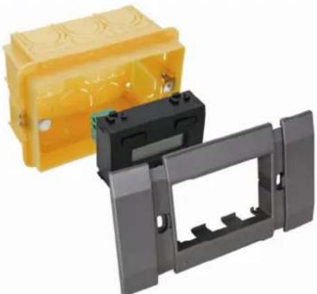
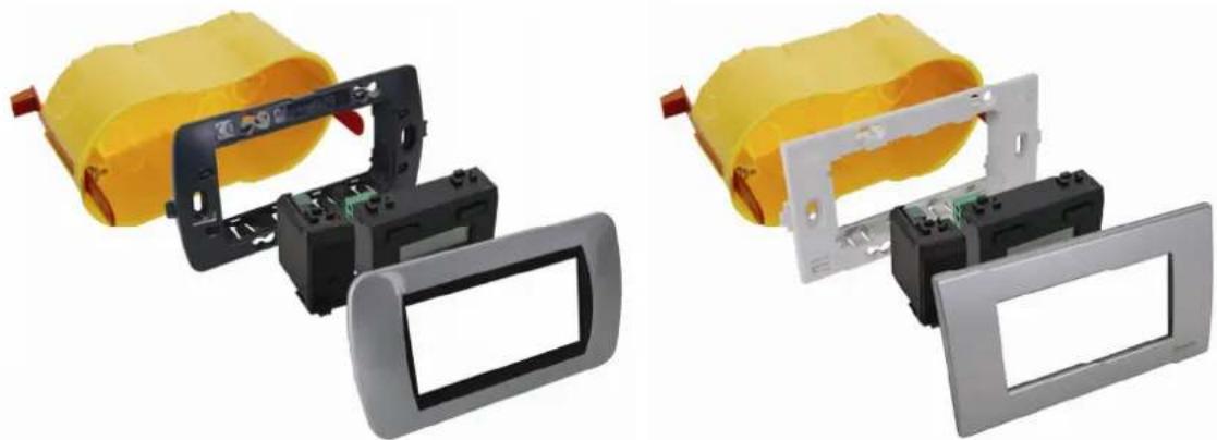
The temperature controller VMB1TC can be embedded in combination with a Velbus cover plate VMBFDG or VMBFLG. Push the modules from the back into the cover plate.
natural_image
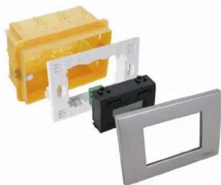
Three plastic enclosures: yellow plastic housing, black plastic casing, and gray plastic cover (no text or symbols visible)It is also possible to use a 3-module wide frame with cover plate from the BTicino Living series. The module must be pushed into the build-in frame from the front.

natural_image
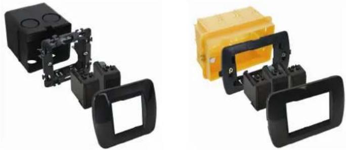
Three electronic components: yellow box, black plastic housing, and black frame (no visible text or symbols)It is also possible to use a 3-module wide frame with cover plate from the BTicino Light or Light Tech series. The module must be pushed into the build-in frame from the front.
natural_image
Three electronic components: a yellow plastic enclosure, a black plastic enclosure with a green indicator, and a gray rectangular frame (no visible text or symbols)To build the controller in into a hollow wall, use a hollow wall pattress.

natural_image
Stacked electronic components including a yellow cylindrical body and black rectangular enclosures (no visible text or symbols)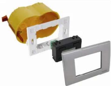
natural_image
Exploded view of a yellow electrical enclosure with a black and silver casing, showing internal components (no text or symbols visible)EMBEDDING A TEMPERATURE SENSOR
The temperature sensor VMB1TS can be embedded in combination with two blank frames VMBFBI and a Velbus cover plate VMBFDG or VMBFLG. Push the modules from the back into the cover plate.

natural_image
Two plastic electrical connectors: a yellow box with internal components and a gray bracket with internal slots (no text or symbols visible)It is also possible to use a 2- or 3-module wide frame with cover plate from the BTicino Living series. The module must be pushed into the build-in frame from the front.
natural_image
Two black plastic enclosure components with mounting brackets, one yellow and one black, shown against white background (no text or symbols)It is also possible to use a 2- or 3-module wide frame with cover plate from the BTicino Light or Light Tech series. The module must be pushed into the build-in frame from the front.

natural_image
Three types of electrical connectors shown in black, yellow, and gray plastic components (no text or symbols visible)To build the sensor in into a hollow wall, use a hollow wall pattress.

natural_image
Four-panel image showing a yellow cylindrical device with black frame and metal bracket, displayed in different angles (no text or symbols visible)EMBEDDING A TEMPERATURE CONTROLLER TOGETHER WITH A SENSOR
The controller (VMB1TC) can be embedded together with a sensor (VMB1TS) in a 4-module wide frame with cover plate from the BTicino Living series. The module must be pushed into the build-in frame from the front.

natural_image
Exterior view of a yellow plastic enclosure with black and gray components, no visible text or symbolsThe controller (VMB1TC) can be build-in together with a sensor (VMB1TS) in a 4-module wide frame with cover plate from the BTicino Light of Light Tech series. The module must be pushed into the build-in frame from the front.

natural_image
Three electronic device modules shown in yellow, white, and black plastic enclosures (no text or symbols visible)To build the controller and sensor in into a hollow wall, use a hollow wall pattress.
natural_image
Two views of a yellow battery pack assembly with internal components and mounting brackets (no text or symbols visible)OVERVIEW HEATING INSTALLATION
A heating installation usually consists of radiators or convectors, a boiler, circulation pump and a collector with valves for every radiator group.
Every room is equipped with a temperature sensor VMB1TS which is controlled by one or multiple temperature controllers VMB1TC. The sensors in turn steer the relay modules VMB4RY (or VMB1RY) that control the valves. As soon as one of the valves is opened, a relay channel can activate the circulation pump and when one of the sensors is in day or comfort mode, a relay channel can put the boiler in day mode. When convectors with built-in fan are used, a relay channel can steer this fan in case the room temperature deviates too much from the desired temperature, e.g. to speed up heating in the morning.

flowchart
graph TD
    A["VMB1TS"] --> B["VMB1TC"]
    C["VMB1TS"] --> D["VMB4RY"]
    E["VMB1TS"] --> F["M"]
    G["VMB1TS"] --> H["VMBTR1"]
    I["VMB1TS"] --> J["VMB3PS"]
    K["VMB1TS"] --> L["VMB4RY"]
    M["VMB1TS"] --> N["VMB1TS"]
    O["VMB1TS"] --> P["VMB1TS"]
    Q["VMB1TS"] --> R["VMB1TS"]
    S["VMB1TS"] --> T["VMB1TS"]
    U["VMB1TS"] --> V["VMB1TS"]
    W["VMB1TS"] --> X["VMB1TS"]
    Y["VMB1TS"] --> Z["VMB1TS"]
    AA["VMB1TS"] --> AB["VMB1TS"]
    AC["VMB1TS"] --> AD["VMB1TS"]
    AE["VMB1TS"] --> AF["VMB1TS"]
    AG["VMB1TS"] --> AH["VMB1TS"]
    AI["VMB1TS"] --> AJ["VMB1TS"]
    AK["VMB1TS"] --> AL["VMB1TS"]
    AM["VMB1TS"] --> AN["VMB1TS"]
    AO["VMB1TS"] --> AP["VMB1TS"]
    AQ["VMB1TS"] --> AR["VMB1TS"]
    AS["VMB1TS"] --> AT["VMB1TS"]
    AU["VMB1TS"] --> AV["VMB1TS"]
    AW["VMB1TS"] --> AX["VMB1TS"]
    AY["VMB1TC"] --> AZ["VMB1TC"]
    BA["VMB1TC"] --> BB["VMB1TC"]
    BC["VMB1TC"] --> BD["VMB1TC"]
    BE["VMB1TC"] --> BF["VMB1TC"]
    BG["VMB1TC"] --> BH["VMB1TC"]
    BI["VMB1TC"] --> BJ["VMB1TC"]
    BK["VMB1TC"] --> BL["VMB1TC"]
    BM["VMB1TC"] --> BN["VMB1TC"]
    BO["VMB1TC"] --> BP["VMB1TC"]
    BQ["VMB1TC"] --> BR["VMB1TC"]
    BS["VMB1TC"] --> BT["VMB1TC"]
    BU["VMB1TC"] --> BV["VMB1TC"]
    BW["VMB1TC"] --> BX["VMB1TC"]
    BY["VMB1TC"] --> BZ["VMB1TC"]
    CA["VMB1TC"] --> CB["VMB1TC"]
    CC["VMB1TC"] --> CD["VMB1TC"]
    BEX["VMB1TC"] --> CE["VMB4RY"]
    BEY["VMB4RY"] --> CE
    BFX["VMB4RY"] --> CE
    BGXD["VMB4RY"] --> CE
    BHXD["VMB4RY"] --> CE
    BIXD["VMB4RY"] --> CE
    BZV["X-05V-05V-05V-05V-05V-05V-05V-05V-05V-05V-05V-05V-05V-05V-05V-05V-05V-05V-05V-05V-05V-05V-05V-05V-05V-05A"]
    BZX["X-05V-05V-05V-05V-05V-05V-05V-05V-05V-05V-05V-05V-05V-05V-05V-05V-05V-05A"]
    BZXX["X-05V-05V-05V-05V-05V-05V-05V-05V-05V-05V-05V-05A"]
    BZXXX["X-05V-05V-05V-05V-05V-05V-05V-05V-05A"]
CONNECTION
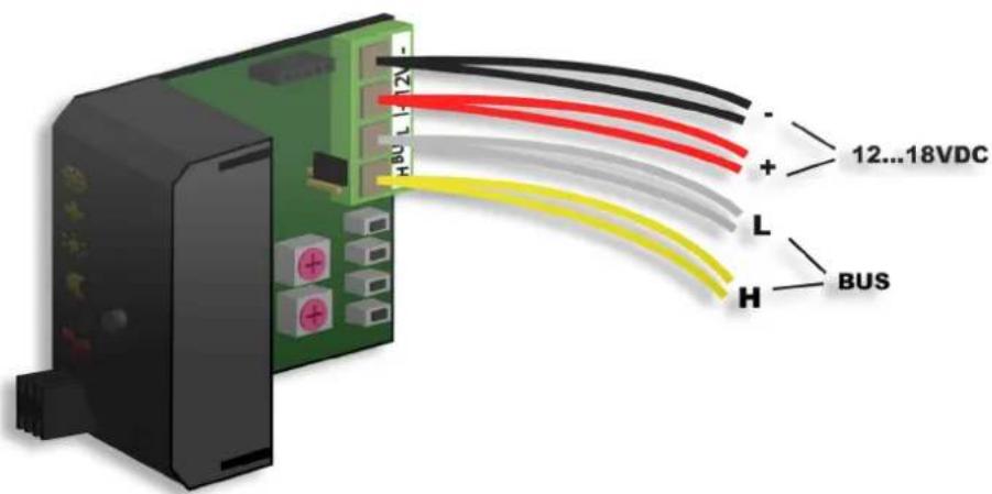
To interconnect the Velbus modules the use of twisted-pair cable (EIB 2x2x0.8mm2, UTP 8x0.51mm - CAT5 or equivalent) is recommended.
Connect the bus to the module (beware of the polarity).
Connect the 12V to 18V direct current to the module (beware of the polarity).
Connecting the temperature controller VMB1TC


Connecting the temperature sensor VMB1TS

Terminator
Normally only 2 'TERM' terminators must be used in a complete Velbus installation. Usually this will be on one module inside the distribution box and on the module which is physically located furthest from the distribution box.

On all other modules, the terminator must be removed.

Remark:
In case the wiring contains a lot of branches, still only one terminator is placed on one module inside the distribution box and one on the module which is physically located furthest from the distribution box. When communication errors occur, an additional terminator can be used at the end of another branch. However, the number of terminators should be limited as more terminators place a heavy load on the bus.
Addressing
Every module on the Velbus system must have its own unique address.
On modules with a rotary switch e.g. the temperature sensor VMB1TS and the relay module VMB4RY the address is set using the 'ADDR' rotary switch (also refer to the manual of the relevant module).
The address of the temperature controller is set via a menu (see § 'configuration of the temperature controller' below). These addresses may not be altered afterwards.
Allocate the relay channels
Every temperature sensor module VMB1TS can steer a relay channel to:
- open the valve that provides hot water to the radiator
- switch on the fan of a convector to speed up heating (when the difference between desired temperature and room temperature is too high)
- set the boiler in day mode
- switch on the air-conditioning
- switch on the circulation pump (when on of the valves is open)
- generate an alarm at low room temperature (heating system down)
- generate an alarm at high room temperature (valve fails to close)
Every relay channel that is steered by a temperature sensor must be placed in instant control, meaning that the TIME1 and MODE/TIME2 rotary switches of the channel on the relay module must be set to position '0'.
The easiest way to allocate those relay channels is by using the Velbus link software via a PC connected to a Velbus interface (VMB1USB, VMB1RS or VMBRSUSB).
However, it is also possible without the aid of a computer (see manual of the temperature sensor module VMB1TS). To set up the previous example of a heating system, use following procedures.
Allocate a relay channel to control valve 1
When room temperature drops below the desired value, the temperature sensor sends a request on the bus to energize a relay. When the room temperature rises above the desired value, another request by the temperature sensor is transmitted over the bus to de-energize the relay.
In our example, the first temperature sensor must control relay channel 3 of the first relay module to steer the valve.
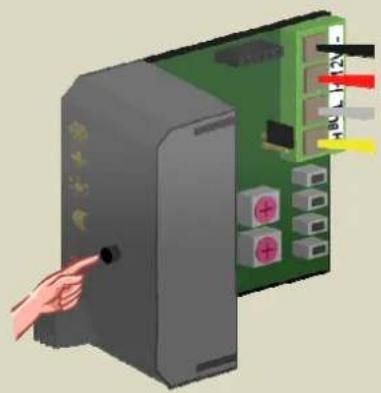
- Set the first sensor module in anti-freeze mode by pressing the push button on the front panel repeatedly until all LEDs are off.

natural_image
Illustration of a hand pointing at a server rack with labeled connectors (no text or symbols present)- Set the MODE and TIME1 rotary switches for channel 3 of the first relay module to '0' (instant control).
- Remember the address of this relay module to reinstate it later on.
- Set the address of the first relay module to 'C3'. The 'MODE 3' LED flashes to indicate push button learning mode (PBM).
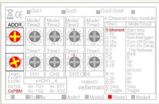
- Press and hold the lowest push button (HEAT) of the first temperature sensor until the relay is energised and the red LED on the sensor module flashes.

natural_image
Illustration of a hand pointing at a green circuit board with multiple connectors (no text or symbols visible)- Set the address of the first relay module back to its original value.
Allocate a relay channel to control valve 2
In our example, the second temperature sensor must control relay channel 4 of the first relay module to steer the valve.
- Set the second sensor module in anti-freeze mode by pressing the push button on the front panel repeatedly until all LEDs are off.
natural_image
Illustration of a hand inserting a cable into a server rack with visible wiring (no text or symbols)- Set the MODE and TIME1 rotary switches for channel 4 of the first relay module to '0' (instant control).
- Remember the address of this relay module to reinstate it later on.
- Set the address of the first relay module to 'C4'. The 'MODE 4' LED flashes to indicate push button learning mode (PBM).

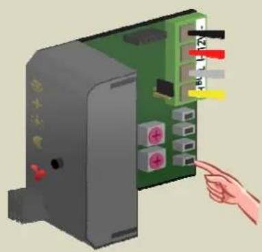
- Press and hold the lowest push button (HEAT) of the second temperature sensor until the relay is energised and the red LED on the sensor module flashes.
natural_image
Illustration of a computer interface with a hand pointing to a green circuit board (no text or symbols visible)- Set the address of the first relay module back to its original value.
Allocate a relay channel to control valve 3
In our example, the third temperature sensor must control relay channel 1 of the second relay module to steer the valve.
- Set the third sensor module in anti-freeze mode by pressing the push button on the front panel repeatedly until all LEDs are off.

natural_image
Illustration of a hand inserting a cable into a server rack with connectors (no text or symbols visible)- Set the MODE and TIME1 rotary switches for channel 1 of the second relay module to '0' (instant control).
- Remember the address of this relay module to reinstate it later on.
- Set the address of the second relay module to 'C1'. The 'MODE 1' LED flashes to indicate push button learning mode (PBM).
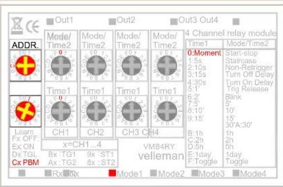
- Press and hold the lowest push button (HEAT) of the third temperature sensor until the relay is energised and the red LED on the sensor module flashes.

natural_image
Illustration of a hand pointing at an electronic circuit board with colored pins (no text or symbols visible)- Set the address of the second relay module back to its original value.
Allocate a relay channel to control the fan
In our example, the fan of the convector must be switched on when the temperature measured by the third temperature sensor deviates too much from the desired value. The fan is steered by relay channel 2 of the second relay module.
- Set the third sensor module in anti-freeze mode by pressing the push button on the front panel repeatedly until all LEDs are off.

natural_image
Illustration of a hand inserting a device into a green circuit board with labeled connectors (no text or symbols present)- Set the MODE and TIME1 rotary switches for channel 2 of the second relay module to '0' (instant control).
- Remember the address of this relay module to reinstate it later on.
- Set the address of the second relay module to 'C2'. The 'MODE 2' LED flashes to indicate push button learning mode (PBM).

- Press and hold the second push button (TURBO) of the third temperature sensor until the relay is energised and the red LED on the sensor module flashes.

natural_image
Illustration of a hand pointing at a green electronic circuit board with multiple switches (no text or symbols visible)- Set the address of the second relay module back to its original value.
Allocate a relay channel for day mode of the boiler
Some boilers can be set to day or night mode. In night mode, the boiler temperature is set approximately 10 degrees lower. In our example, the boiler must be switched to day mode as soon as one of the sensor modules is in day or comfort mode. This is accomplished through relay channel 1 of the first relay module.
- Set all sensor modules in anti-freeze mode by pressing the push button on the front panel repeatedly until all LEDs are off.

natural_image
Illustration of a hand inserting a cable into a server rack with connectors (no text or symbols visible)- Set the MODE and TIME1 rotary switches for channel 1 of the first relay module to '0' (instant control).
- Remember the address of this relay module to reinstate it later on.
- Set the address of the first relay module to 'C1'. The 'MODE 1' LED flashes to indicate push button learning mode (PBM).

- Press and hold the third push button (DAY) of the first temperature sensor until the relay is energised and the red LED on the sensor module flashes.

natural_image
Illustration of a hand inserting a green circuit board into a terminal block (no text or symbols visible)- Press and hold the third push button (DAY) of the second temperature sensor until the relay is energised and the red LED on the sensor module flashes.

natural_image
Illustration of a hand inserting a green circuit board into a terminal block (no text or symbols visible)- Press and hold the third push button (DAY) of the third temperature sensor until the relay is energised and the red LED on the sensor module flashes.

natural_image
Illustration of a hand inserting a green circuit board into a black box (no text or symbols visible)- Set the address of the first relay module back to its original value.
Allocate a relay channel for the circulation pump
Some valves have a contact that closes when the valve is open. By wiring all the contacts in parallel, the circulation pump can be steered. For valves that do not have these contacts, a relay can be assigned to the temperature sensors to steer the circulation pump.
In our example the pump must be active as soon as one of the sensor modules indicates heating is required. This is done through relay channel 2 of the first relay module.
- Set all sensor module in anti-freeze mode by pressing the push button on the front panel repeatedly until all LEDs are off

natural_image
Illustration of a hand inserting a cable into a server rack with colored connectors (no text or symbols visible)- Set the MODE and TIME1 rotary switches for channel 2 of the first relay module to '0' (instant control).
- Remember the address of this relay module to reinstate it later on.
- Set the address of the first relay module to 'C2'. The 'MODE 2' LED flashes to indicate push button learning mode (PBM).

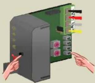
- Press and hold the pushbutton on the front panel of the first temperature sensor and simultaneously press and hold the lowest push button (HEAT) until the relay is energised and the red LED on the sensor module flashes. First release the lowest push button (HEAT) followed by the push button on the front panel.

natural_image
Illustration of hands inserting a computer into a server rack (no text or symbols visible)- Press and hold the pushbutton on the front panel of the second temperature sensor and simultaneously press and hold the lowest push button (HEAT) until the relay is energised and the red LED on the sensor module flashes. First release the lowest push button (HEAT) followed by the push button on the front panel.

natural_image
Illustration of hands inserting a computer into a server rack with visible ports and connectors (no text or symbols)- Press and hold the pushbutton on the front panel of the third temperature sensor and simultaneously press and hold the lowest push button (HEAT) until the relay is energised and the red LED on the sensor module flashes. First release the lowest push button (HEAT) followed by the push button on the front panel.
natural_image
Illustration of hands inserting a device into a computer tower (no text or symbols visible)- Set the address of the first relay module back to its original value.
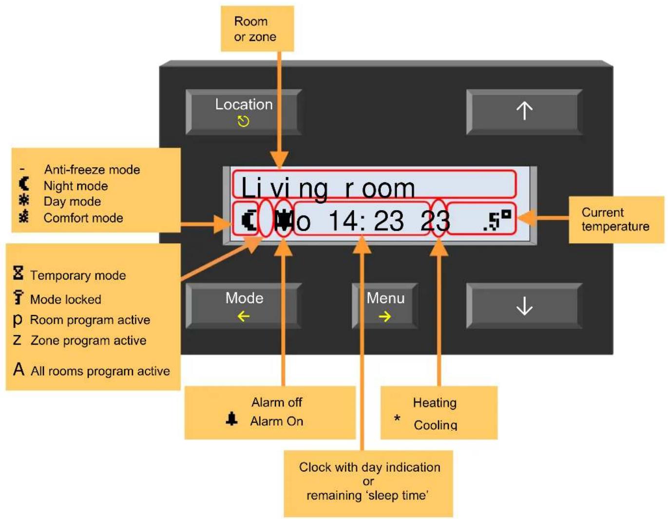
SCREEN INDICATIONS
flowchart
graph TD
    A["Room or zone"] --> B["Location"]
    B --> C["Living room"]
    C --> D["Current temperature"]
    C --> E["Mode"]
    C --> F["Menu"]
    C --> G["Alarm off"]
    C --> H["Alarm On"]
    C --> I["Heating Cooling"]
    C --> J["Clock with day indication or remaining 'sleep time'"]
    K["Anti-freeze mode"] --> C
    L["Night mode"] --> C
    M["Day mode"] --> C
    N["Comfort mode"] --> C
    O["Temporary mode"] --> C
    P["Mode locked"] --> C
    Q["Room program active"] --> C
    R["Zone program active"] --> C
    S["All rooms program active"] --> C
LED INDICATION
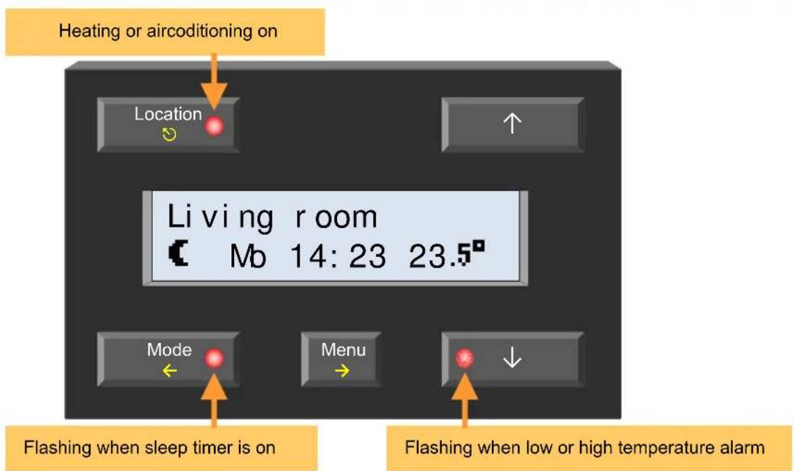
flowchart
graph TD
    A["Heating or airconditioning on"] --> B["Location"]
    B --> C["Living room Mb 14: 23 23.5°"]
    D["Mode"] --> E["Flashing when sleep timer is on"]
    F["Menu"] --> G["Flashing when low or high temperature alarm"]
Remark: When a menu is active, de LED indication is replaced with flashing LEDs on the ↑ and ↓ buttons that indicate the scrolling direction.
BUTTON FUNCTIONS


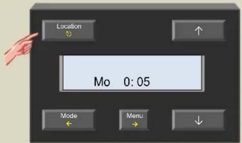
Location
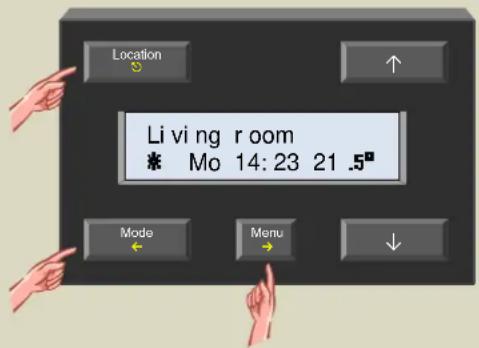
Change room or zone.
Push and hold to switch between rooms and zones.

Exit the menu.
Changes made in a data entry screen (flashing item) are discarded.


Mode
Switch between anti-freeze, night, day and comfort mode and start the sleep timer.
Push and hold to stop the sleep timer.

Move one level back in the menu.
Changes made in a data entry screen (flashing item) are discarded.
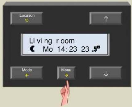

Menu
Open the menu.
Push and hold to open the extended menu.

Changes made in a data entry screen (flashing item) are retained.


Alter the data entry (flashing item) or scroll through the menu.
Direct access menu

- Open the menu by pressing the 'Menu' button.
- Scroll through the menu with the ↑ or ↓ button.

-
This menu is only available when temporary mode (sleep timer) is activated.
-
Select a menu item with the → button.
- Scroll through sub menus with the ↑ or ↓ button and select with the → button.
- Alter the data entry field (flashing item) with the ↑ or ↓ button.
- Confirm or move to the next data entry field with the → button.
- To cancel or return to the previous item, use the ← button.
- Quit the menu using the ⏻ button.
When a data entry field (flashing item) is still active, changes are discarded when using the Ⓧ button.
Extended menu
To change the program, settings or statistics of the different sensors or to change the configuration of the temperature controller, use the extended menu. This extended menu can be secured by setting a PIN.
- Open the extended menu by pushing and holding the 'Menu' button for about 4 seconds.
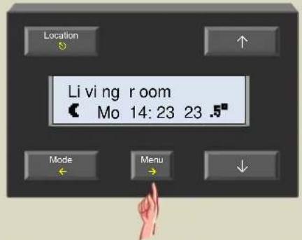
If the menu is not protected by a PIN, steps 2 to 5 are skipped.
- Select the first number of the PIN using the ↑ or ↓ button and confirm with the → button.

- Select the second number of the PIN using the ↑ or ↓ button and confirm with the → button.

- Select the third number of the PIN using the ↑ or ↓ button and confirm with the → button.

- Select the last number of the PIN using the ↑ or ↓ button and confirm with the → button.
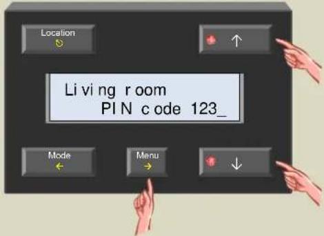
- The first item of the extended menu is shown on the display.

- Scroll through the menu using the ↑ and ↓ buttons.
| Program | ||
| Settings | ||
| Operating | mode | |
| Button | lock | |
| Sleep | timer | |
| Low | temp. alarm | |
| High temp. alarm | ||
| Anti-freeze | temp | |
| Upper heat temp | ||
| Lower | cool temp | |
| Upper | cool temp | |
| Hysteresis | ||
| Temp | difference | |
| Unjam | pump | |
| Unjam | valve | |
| Local | program | |
| Zone | number | |
| Diff. | Sensor | |
| Sensor | cal. | |
| Change | name | |
| To main menu | ||
| Configuration | |
| Language | |
| Temp. | read-out |
| Master | clock |
| Global | alarm |
| Battery | backup |
| Change | PIN |
| Firmware | version |
| Address1 | |
| Link | wake-up |
| Link | go-to-bed |
| Scan | sensors |
| To main menu | |
| Display |
| Contrast |
| Backlight |
| To main menu |
| Statistics1 | ||
| Min | temp 16.0° | |
| Max temp 23.0° | ||
| - | 0m/5m | |
| 0m/5m | ||
| 8m/1h10m | ||
| 10m/1h15m | ||
| 18m/2h35m | ||
| To main menu | ||
Exit
- This menu is not available when a zone or 'all rooms' is selected.
- This menu is not available when 'all rooms' is selected.
Note:
The naming of the menus and sub-menus might differ depending on the controllers' firmware version. Always make sure to use the latest firmware version.
- Select the menu item with the → button.
- When applicable, scroll through the sub menus with the ↑ or ↓ button and select with the → button.
- Change the data entry field (flashing item) using the ↑ or ↓ button.
- Confirm or move to the next entry field with the → button.
- Cancel or return to the previous item by using the ← button.
- Exit the menu with the Ⓧ button. When a data entry field (flashing item) is still active, changes are discarded when using the Ⓧ button.
Choice of language
The menu text can be displayed in different languages. Factory default is English, but the language can be set to French, Dutch, Spanish or German.
- When applying power to the controller for the first time, only the time is shown on the display.

- Press and hold the 'Menu' button for ±4 seconds to open the extended menu.

- If necessary scroll through the extended menu using the ↑ or ↓ button until the 'Configuration' item appears

- Select the configuration menu with the → button.
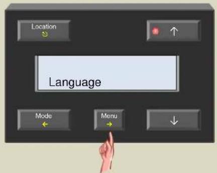
- Select the language menu with the → button.
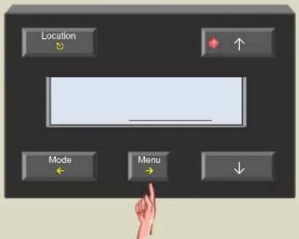
- Choose the desired language with the or button.
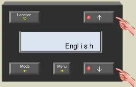
- Confirm the language selection with the → button.
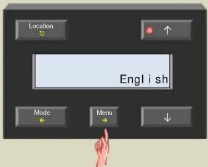
- Exit the menu with the ⏻ button.

Temperature read-out (°Celsius or °Fahrenheit)
Default setting for the temperature read-out is degrees Celsius. Change the setting to see the read-out in degrees Fahrenheit.
- Press and hold the 'Menu' button for ±4 seconds to open the extended menu.

- If necessary scroll through the extended menu using the ↑ or ↓ button until the 'Configuration' item appears

- Select the configuration menu with the → button.
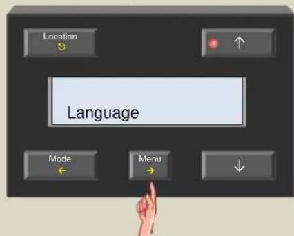
- Scroll through the configuration menu using the ↑ or ↓ button until the 'Temp. Read-out' item appears.

- Select the temperature Readout menu with the → button.

- Set the read-out to °Celsius or °Fahrenheit using the ↑ or ↓ button.

- Confirm the read-out setting with the → button.

- Exit the menu with the ⏻ button.
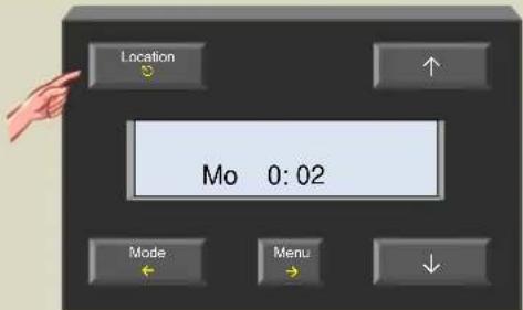
Master clock
When your Velbus installation contains multiple modules with built-in clock (temperature controllers VMB1TC and control panel VMB4PD) it is important that all clocks have the same time setting. This can be achieved by setting the clock of one module as reference (master). This module will then synchronize the other module clocks every day. This function is default disabled.
- Press and hold the 'Menu' button for ±4 seconds to open the extended menu.

- If necessary scroll through the extended menu using the ↑ or ↓ button until the 'Configuration' item appears
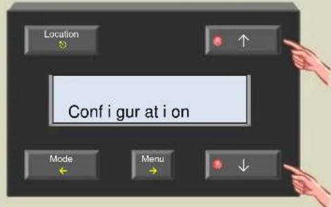
- Select the configuration menu with the → button.
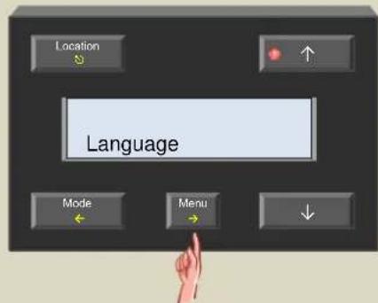
- Scroll through the configuration menu using the ↑ or ↓ button until the 'Master clock' item appears.

- Select the temperature Master clock menu with the → button.
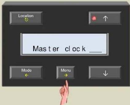
- Switch the master clock on or off using the ↑ or ↓ button.

- Confirm the master clock setting with the → button.
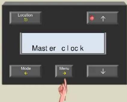
- Exit the menu with the ⏻ button.

Global alarm
This setting only applies when multiple temperature controllers are connected to your Velbus installation. Default the global alarm function is disabled. Changing the alarm time on a module that has the global alarm function enabled will result in changing the alarm time on all temperature controllers that have the global alarm function enabled. For modules that have the global alarm time disabled, changes in alarm time will only apply to that module.
- Press and hold the 'Menu' button for ±4 seconds to open the extended menu.

- If necessary scroll through the extended menu using the ↑ or ↓ button until the 'Configuration' item appears
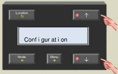
- Select the configuration menu with the → button.

- Scroll through the configuration menu using the ↑ or ↓ button until the 'Global alarm clk' item appears.

- Select the global alarm menu with the → button.
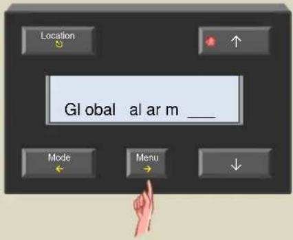
- Switch the global alarm function on or off using the ↑ or ↓ button.
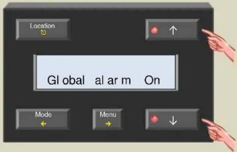
- Confirm the global alarm setting with the → button.

- Exit the menu with the ⏻ button.

Battery backup
To avoid losing the clock when a power failure occurs, a backup battery (3V Lithium CR2032) can be installed in the battery holder at the back of the module.
To avoid premature depletion of the battery, only install it when permanent power is supplied to the Velbus system.

The temperature controller can display a message when the battery needs replacement.

The battery voltage watchdog must be enabled through the configuration menu.
- Press and hold the 'Menu' button for ±4 seconds to open the extended menu.

- If necessary scroll through the extended menu using the ↑ or ↓ button until the 'Configuration' item appears

- Select the configuration menu with the → button.

- Scroll through the configuration menu using the ↑ or ↓ button until the 'Battery backup' item appears.
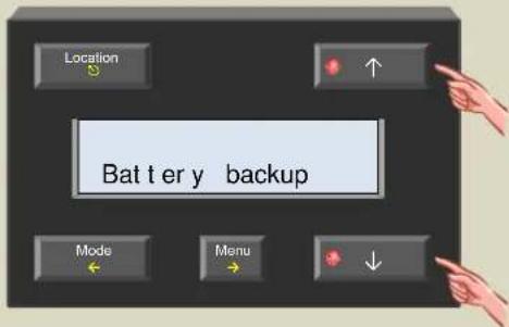
- Select the battery backup menu with the → button.

- Enable the battery backup watchdog when a battery is inserted or disable it when no battery is present using the ↑ or ↓ button.

- Confirm the battery backup setting with the → button.
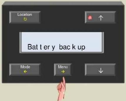
- Exit the menu with the ⏻ button.
Addressing
Every module on the Velbus system must have its own unique address. On modules with a rotary switch the address is set using the 'ADDR' rotary switch (refer to the manual of the relevant module). On other modules e.g. the temperature controller the address is set via the menu. These addresses may not be altered afterwards.
- Press and hold the 'Menu' button for ±4 seconds to open the extended menu.

- If necessary scroll through the extended menu using the ↑ or ↓ button until the 'Configuration' item appears
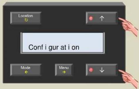
- Select the configuration menu with the → button.
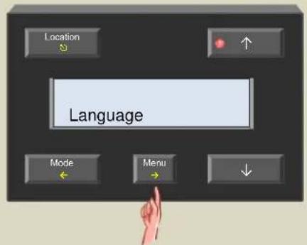
- Scroll through the configuration menu using the ↑ or ↓ button until the 'Address' item appears.

- Select the Address menu with the → button.

- Enter a unique address ('01'... 'FE') using the ↑ or ↓ button.

- Confirm the address with the → button.

- Exit the menu with the ⏻ button.

Assign an action to the wake-up time
The wake-up time can be used with the thermostat program but also to perform a certain action e.g. switching off staircase lighting, opening the roll-down window shutters, switching certain mains outlets on or off...
As an example, we will automatically open all roll-down window shutters as soon as the set wake-up time is reached. This can also be configured through the Velbus link software on the computer but here we explain the manual procedure.
- Remember all address settings of the shutter modules to reinstate them later on.
- Set the addresses of all shutter modules to 'E1' to learn the immediately up action for channel 1. The 'Mode Up1' LEDs are flashing to indicate the learning mode.

- Press and hold the 'Menu' button for ±4 seconds to open the extended menu.
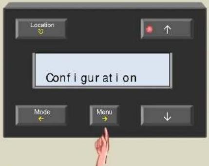
- If necessary scroll through the extended menu using the ↑ or ↓ button until the 'Configuration' item appears.
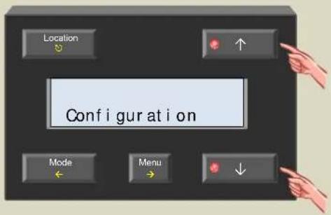
- Select the configuration menu with the → button.

- Scroll through the configuration menu using the ↑ or ↓ button until the 'Link wake-up' item appears.
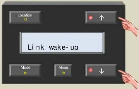
- Select the link wake up menu with the → button. As a confirmation, the relays of the window shutter modules are energised.

- Confirm with the → button.
The relays of the window shutter modules are de-energised.

- Exit the menu with the ⏻ button.

- Now set the addresses of all shutter modules to 'E2' to learn the immediately up action for channel 2. The 'Mode Up2' LEDs are flashing to indicate the learning mode.

- Press and hold the 'Menu' button for ±4 seconds to open the extended menu.

- If necessary scroll through the extended menu using the ↑ or ↓ button until the 'Configuration' item appears

- Select the configuration menu with the → button.

- Scroll through the configuration menu using the ↑ or ↓ button until the 'Link wake up' item appears.

- Select the link wake up menu with the → button. As a confirmation, the relays of the window shutter modules are energised.

- Confirm with the → button.
The relays of the window shutter modules are de-energised.
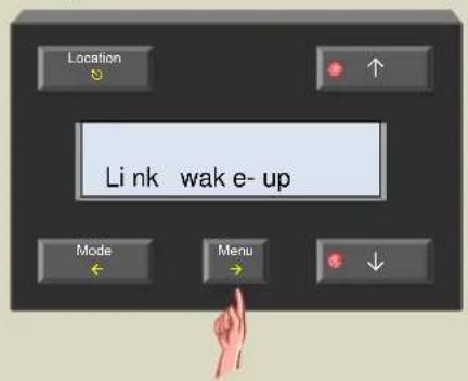
17.Exit the menu with the ⏻ button.

- Set the addresses of the window shutter modules back to their original value.
Assign an action to the go-to-bed time
The go-to-bed time can be used with the thermostat program but also to perform a certain action e.g. switching on staircase lighting, closing the roll-down window shutters, switching certain mains outlets off...
As an example, we will automatically switch on the staircase lighting as soon as the set go-to-bed time is reached. This can also be configured through the Velbus link software on the computer but here we explain the manual procedure.
- Remember the address of the relay module to reinstate it later on.
- Set the address of the relay module to 'E1' to learn the on-function of the staircase lighting that is connected to channel 1. The 'Mode 1' LEDs are flashing to indicate the learning mode.

- Press and hold the 'Menu' button for ±4 seconds to open the extended menu.
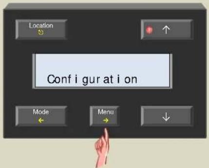
- If necessary scroll through the extended menu using the ↑ or ↓ button until the 'Configuration' item appears.

- Select the configuration menu with the → button.

- Scroll through the configuration menu using the ↑ or ↓ button until the 'Link go-to-bed' item appears.

- Select the link go to bed menu with the → button. As a confirmation, the relay of channel 1 is energised.

- Confirm with the → button.
The relay is de-energised.

- Exit the menu with the Ⓧ button.

- Set the address of the relay module back to its original value.
Searching for temperature sensors
Before the controller can work together with the temperature sensors VMB1TS it must first scan the network for all connected temperature sensors.
When temperature sensors are installed or removed afterwards, the search process must be repeated to update the list of sensors to the new situation.
- Press and hold the 'Menu' button for ±4 seconds to open the extended menu.

- If necessary scroll through the extended menu using the ↑ or ↓ button until the 'Configuration' item appears.

- Select the configuration menu with the → button.

- Scroll through the configuration menu using the ↑ or ↓ button until the 'Scan sensors' item appears.

- Select the scan sensors menu with the → button. The search for sensors on the network is now in progress.

- Once the search process is completed, the first of the connected temperature sensors is shown on the display.
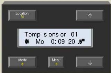
Setting the clock
This module works together with one or more temperature sensoresVMB1TS to form a programmable thermostat. It is important to set the right time for the internal clock.
Setting the time on this module will set the clocks of all clock containing modules that are connected to the Velbus simultaneously.
- Open the menu by pressing the 'Menu' button.

- Scroll through the menu using the ↑ button until the 'Clock set' item appears.

- Select the set clock menu with the → button. The day-indication flashes.

- Set the day with the ↑ or ↓ button.
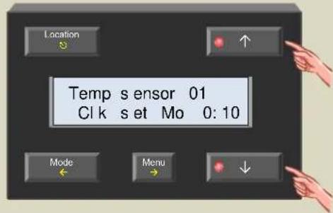
- Confirm with the → button. The hour-indication flashes.
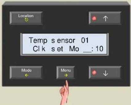
- Set the hour with the ↑ or ↓ button.
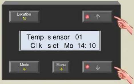
- Confirm with the → button. The minutes-indication flashes.
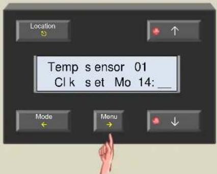
- Set the minutes with the ↑ or ↓ button.

- Confirm with the → button to start the clock from the set time.

10.Exit the menu with the Ⓧ button.

Setting the alarm clock
The module contains an alarm clock that can be enabled or disabled. The alarm times can be used in a thermostat program but also to control an output module (e.g. a relay module).
E.g. the wake-up time can be used to switch on the heating while the go-to-bed time can be used to switch the heating off.
- Open the menu by pressing the 'Menu' button.
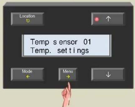
- Scroll through the menu using the ↑ button until the 'Alarm set' item appears.
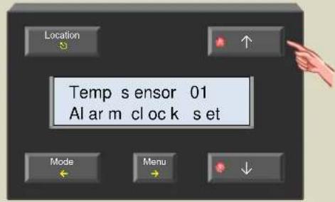
- Select the alarm set menu with the → button. The alarm-indication flashes.

- Set the alarm clock function with the or button.
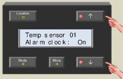
- Confirm with the → button. The hour-indication of the wake-up time flashes.

- Set the hour of the wake-up time with the ↑ or ↓ button.

- Confirm with the → button. The minutes-indication of the wake-up time flashes.

- Set the minutes of the wake-up time with the ↑ or ↓ button.

- Confirm with the → button.
The hour-indication of the go-to-bed time flashes.

- Set the hour of the go-to-bed time with the ↑ or ↓ button.

- Confirm with the → button.
The minutes-indication of the go-to-bed time flashes.

- Set the minutes of the go-to-bed time with the ↑ or ↓ button.
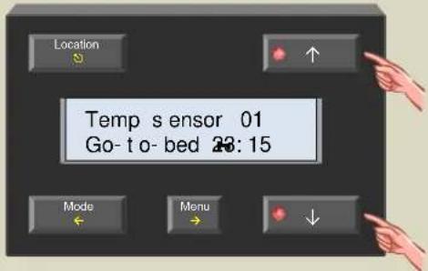
- Confirm with the → button.

- Exit the menu with the ⏻ or ← button.

The ⚙ symbol indicates that the alarm function is activated.
Disabling the alarm clock function
If the use of the alarm clock is no longer desired, the alarm function can be disabled. The actions and program instructions that are linked to the alarm times are suspended.
- Open the menu by pressing the 'Menu' button.
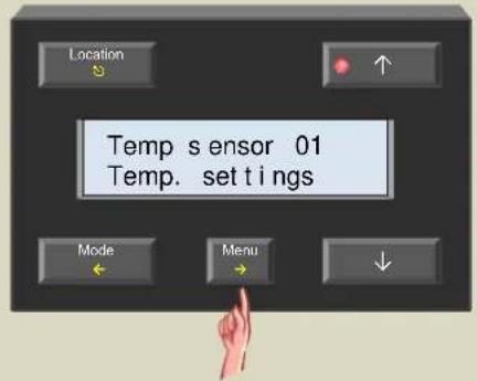
- Scroll through the menu using the ↑ button until the 'Alarm set' item appears.
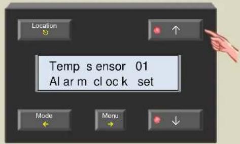
- Select the alarm set menu with the → button. The alarm-indication flashes.

- Disable the alarm clock function with the or button.
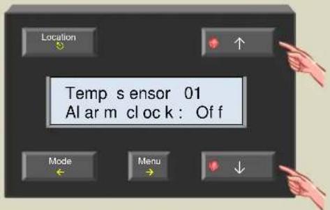
- Confirm with the → button.

- Exit the menu with the ⏻ or ← button.

The symbol is no longer visible on the display to indicate that the alarm function is disabled.
Setting the display contrast
Depending on the mounting location of the controller, it might be necessary to adjust the contrast settings of the display to increase readability.
- Press and hold the 'Menu' button for ±4 seconds to open the extended menu.
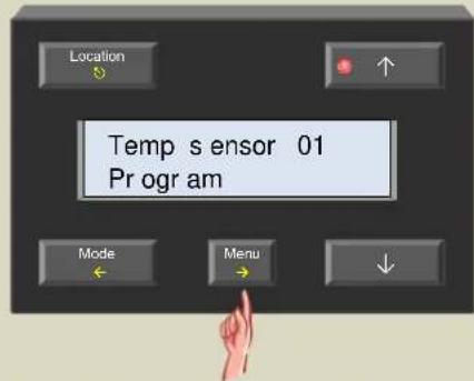
- Scroll through the extended menu using the ↑ or ↓ button until the 'Display' item appears.

- Select the display menu with the → button.

- Select the contrast menu with the → button.

- Change the contrast with the ↑ or ↓ button.
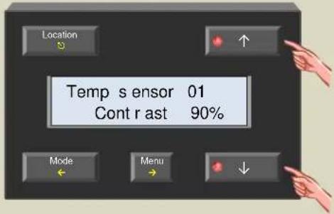
- Confirm with the → button.
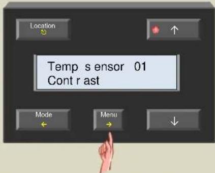
- Exit the menu with the ⏻ button.

Setting the backlight of the display
The backlight of the display can be changed automatically twice a day. When operating the controller the backlight illumination is immediately set to maximum; after ± 1 minute of inactivity, the backlight will return to its original setting.
- Press and hold the 'Menu' button for ±4 seconds to open the extended menu.

- Scroll through the extended menu using the ↑ or ↓ button until the 'Display' item appears
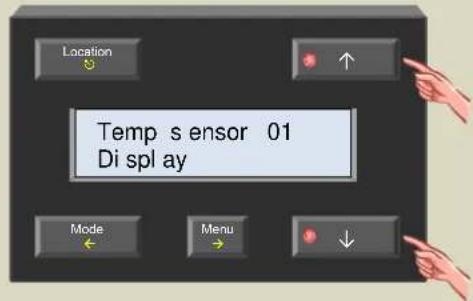
- Select the display menu with the → button.

- Scroll through the display menu using the ↑ or ↓ button until the 'Backlight' item appears.
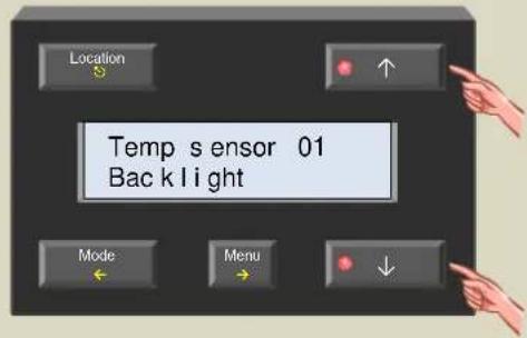
- Select the backlight menu with the → button.

- Change the hour of the first time frame with the ↑ or ↓ button and confirm with the → button.

- Change the minutes of the first time frame with the ↑ or ↓ button and confirm with the → button.

- Set the brightness for the first time frame with the ↑ or ↓ button and confirm with the → button.
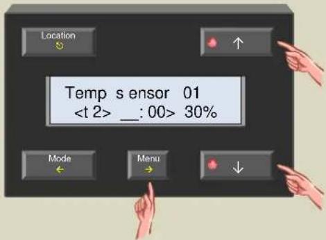
- Change the hour of the second time frame with the ↑ or ↓ button and confirm with the → button.
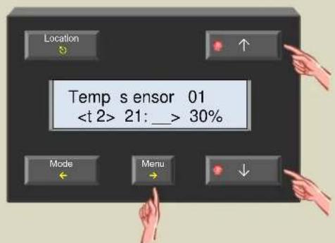
- Change the minutes of the second time frame with the ↑ or ↓ button and confirm with the → button.

- Set the brightness for the second time frame with the or button and confirm with the → button.

- Exit the menu with the ⏻ button.

Assign sensor names
Default all the temperature sensors will have the same name ('Temp sensor xx'). To distinguish between the different temperature sensors it is strongly advised to assign a more meaningful name (e.g. the name of the room) to each sensor.
- Press and hold the 'Menu' button for ±4 seconds to open the extended menu.
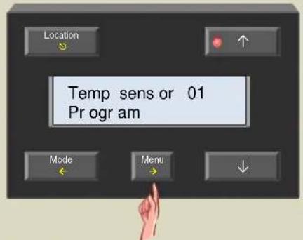
- Scroll through the extended menu using the ↑ or ↓ button until the 'Sensor settings' item appears.

- Select the sensor settings menu with the → button.

- Scroll through the sensor settings menu using the ↑ or ↓ button until the 'Change name' item appears.
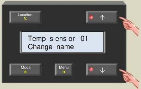
- Select the change name menu with the → button. The cursor flashes on the first character of the name. The second line indicates the address of the selected temperature sensor. With this address the location of the sensor can be determined.

- Change the character at the cursor location with the ↑ or ↓ button and confirm with the → button. The cursor moves to the next character.
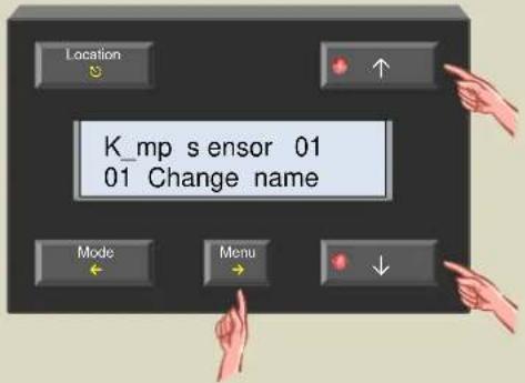
- Repeat step 6 until all characters are entered.

- Exit the menu with the ⏻ button.
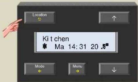
- Press the 'Location' button to select the next sensor.

- Repeat steps 1 through 9 until every sensor has a meaningful name.
Defining zones
It could be interesting to group different sensors in a zone. When that zone is selected, all operations on the controller will be applicable for all sensors that belong to that zone. This way operating the system can be greatly facilitated.
It is possible to define up to 7 zones e.g. ground floor, second floor, bedrooms ...
Default temperature sensors are not assigned to a zone. To assign them to a zone the procedure below should be followed.
- Press the 'Location' button repeatedly until the sensor that will to be added to a zone is displayed.

- Press and hold the 'Menu' button for ±4 seconds to open the extended menu.
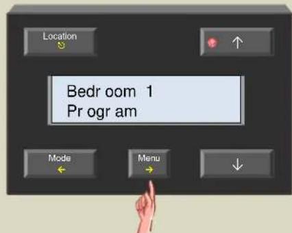
- Scroll through the extended menu using the ↑ or ↓ button until the 'Sensor settings' item appears.

- Select the sensor settings menu with the → button.

- Scroll through the sensor settings menu using the ↑ or ↓ button until the 'Zone number' item appears

- Select the zone number menu with the → button.

- Change the zone with the ↑ or ↓ button. Option ‘---’ indicates that the sensor does not belong to a zone.

- Confirm with the → button.

- Exit the menu with the Ⓧ button.
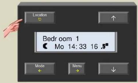
- Repeat steps 1 through 9 for every sensor that needs to be added to a zone.
Change the default zone names
De names 'Zone 1', 'Zone 2' until 'Zone 3' can be changed into more meaningful names.
- Press the 'Location' button repeatedly until the desired zone is displayed.
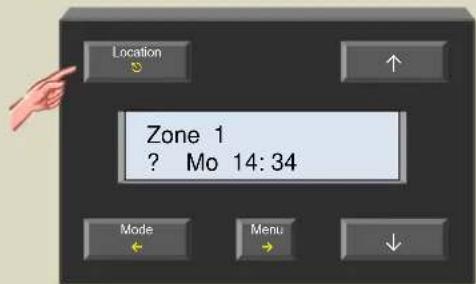
- Press and hold the 'Menu' button for ±4 seconds to open the extended menu.

- Scroll through the extended menu using the ↑ or ↓ button until the 'Sensor settings' item appears.

- Select the sensor settings menu with the → button.

- Scroll through the sensor settings menu using the ↑ or ↓ button until the 'Change name' item appears.
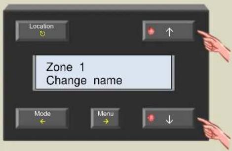
- Select the change name menu with the → button. The cursor flashes on the first character of the name. The second line indicates zone number.
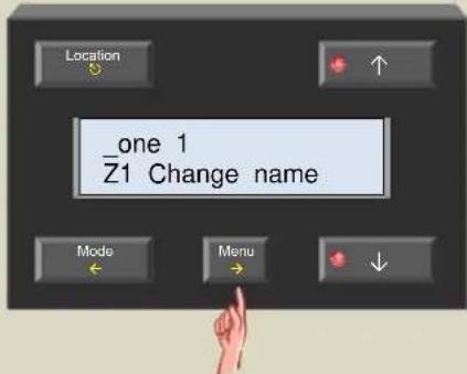
- Change the character at the cursor location with the ↑ or ↓ button and confirm with the → button. The cursor moves to the next character.

- Repeat step 7 until all characters are entered.

- Exit the menu with the ⏻ button.

- Press the 'Location' button to select the next zone.

- Repeat steps 2 through 10 until every zone has a meaningful name.
Heating or cooling mode
Default the sensor is programmed for heating installations. It is possible however to use it for controlling air-conditioning systems.
- Press the 'Location' button repeatedly until the desired sensor or zone is displayed.
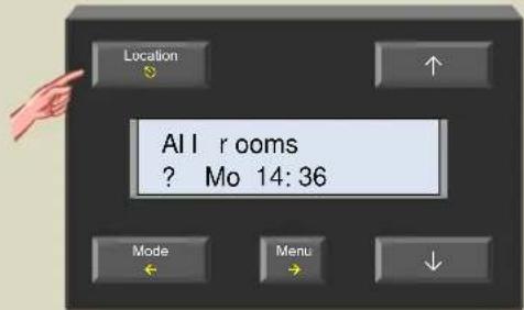
- Press and hold the 'Menu' button for ±4 seconds to open the extended menu.

- Scroll through the extended menu using the ↑ or ↓ button until the 'Sensor settings' item appears.

- Select the sensor settings menu with the → button.

- Select the operating mode menu with the → button.

- Change the mode to heating or cooling using the ↑ or ↓ button.

- Confirm with the → button.

- Exit the menu with the ⏻ button.

Lock or unlock local mode setting
It is possible to switch between comfort, day, and night or anti-freeze mode locally on every temperature sensor. This can be avoided by disabling the function on the temperature sensor(s).
- Press the 'Location' button repeatedly until the desired sensor or zone is displayed.

- Press and hold the 'Menu' button for ±4 seconds to open the extended menu.
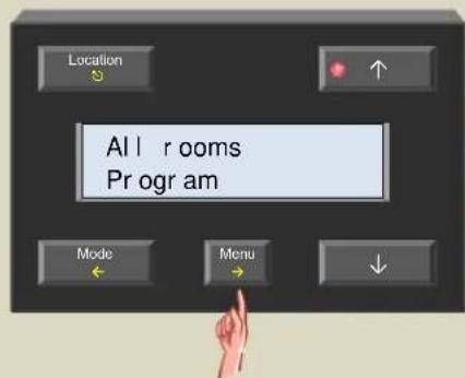
- Scroll through the extended menu using the ↑ or ↓ button until the 'Sensor settings' item appears.

- Select the sensor settings menu with the → button.
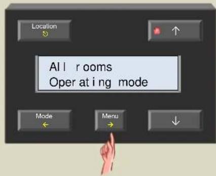
- Scroll through the sensor settings menu using the ↑ or ↓ button until the 'Button lock' item appears.

- Select the keyboard menu with the → button.

- Lock or unlock using the or button.

- Confirm with the → button.

- Exit the menu with the ⏻ button.
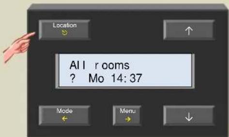
Default duration of temporary mode (default sleep time)
The thermostat program can be temporary ignored by using the sleep timer. The default duration of this sleep time can be set.
- Press the 'Location' button repeatedly until the desired sensor or zone for which the default sleep time will be set is displayed.

- Press and hold the 'Menu' button for ±4 seconds to open the extended menu.

- Scroll through the extended menu using the ↑ or ↓ button until the 'Sensor settings' item appears.

- Select the sensor settings menu with the → button.

- Scroll through the sensor settings menu using the ↑ or ↓ button until the 'Sleep timer' item appears.

- Select the sleep timer menu with the → button.

- Change the 'sleep time' using the ↑ or ↓ button.

- Confirm with the → button.

- Exit the menu with the ⏻ button.

Low temperature alarm
The sensor can trigger an alarm when the temperature drops below a defined value. This could be useful when the heating system shuts down and the temperature reaches freezing point.
- Press the 'Location' button repeatedly until the desired sensor or zone for which the low temperature alarm must be set is displayed.

- Press and hold the 'Menu' button for ±4 seconds to open the extended menu.

- Scroll through the extended menu using the ↑ or ↓ button until the 'Sensor settings' item appears.

- Select the sensor settings menu with the → button.

- Scroll through the sensor settings menu using the ↑ or ↓ button until the 'Low temp. alarm' item appears.
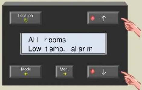
- Select the temp. alarm menu with the → button.

- Change the alarm temp. using the ↑ or ↓ button.
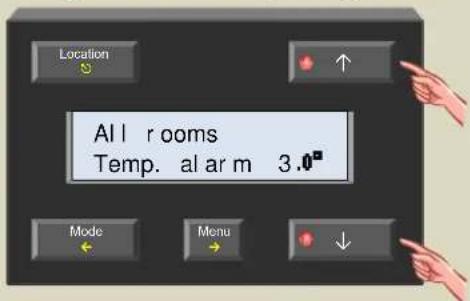
- Confirm with the → button.

- Exit the menu with the ⏻ button.

High temperature alarm
The sensor can trigger an alarm when the temperature rises above a defined value. This could be useful when a valve fails to close and the room would keep heating up.
- Press the 'Location' button repeatedly until the desired sensor or zone for which the high temperature alarm will be set is displayed.

- Press and hold the 'Menu' button for ±4 seconds to open the extended menu.
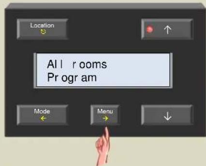
- Scroll through the extended menu using the ↑ or ↓ button until the 'Sensor settings' item appears.
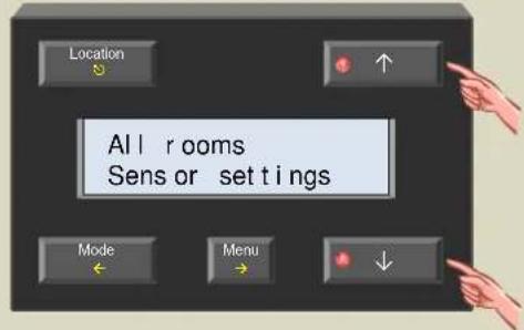
- Select the sensor settings menu with the → button.
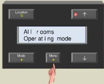
- Scroll through the sensor settings menu using the ↑ or ↓ button until the 'High temp. alarm' item appears.
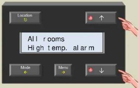
- Select the temp. alarm menu with the → button.

- Change the alarm temp. using the ↑ or ↓ button.

- Confirm with the → button.

- Exit the menu with the ⏻ button.
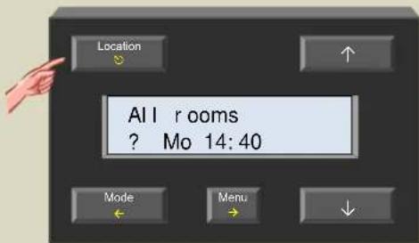
Anti-freeze temperature
This is the lowest allowed room temperature. When temperature reaches or drops below freezing temperature, the heating will always switch on.
- Press the 'Location' button repeatedly until the desired sensor or zone for which the anti-freeze temperature will be set is displayed.

- Press and hold the 'Menu' button for ±4 seconds to open the extended menu.
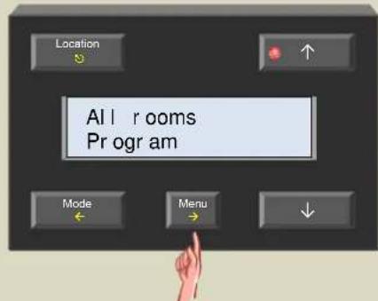
- Scroll through the extended menu using the ↑ or ↓ button until the 'Sensor settings' item appears.

- Select the sensor settings menu with the → button.

- Scroll through the sensor settings menu using the ↑ or ↓ button until the 'Anti-freeze temp.' item appears.

- Select the anti-freeze temperature menu with the → button.
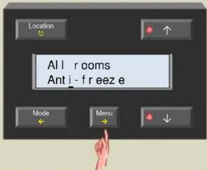
- Set the anti-freeze temp. with the or button.
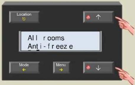
- Confirm with the → button.

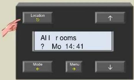
- Exit the menu with the Ⓧ button.
Heating limit
This is the maximum desired room temperature that can be set. Default it is set to 30irc but the user can change this limit. This could be useful to make sure that the desired room temperature is never set to a value higher than a certain predefined value.
- Press the 'Location' button repeatedly until the desired sensor or zone for which the upper heat temp. will be set is displayed.

- Press and hold the 'Menu' button for ±4 seconds to open the extended menu.

- Scroll through the extended menu using the ↑ or ↓ button until the 'Sensor settings' item appears.
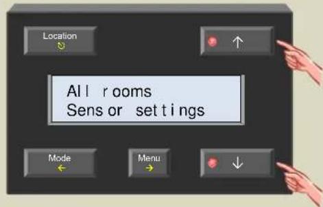
- Select the sensor settings menu with the → button.
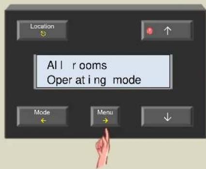
- Scroll through the sensor settings menu using the ↑ or ↓ button until the 'Upper heat temp' item appears.
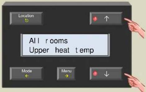
- Select the upper heat temp. menu with the → button.

- Set the upper heat temp. with the or buttons.

- Confirm with the → button.

- Exit the menu with the ⏻ button.

Minimum cooling temperature
This is the minimum desired room temperature that can be set for the air conditioner. Default it is set to 16irc but the user can change this limit. This could be useful to make sure that the air conditioner is never set to a value lower than a certain predefined value.
- Press the 'Location' button repeatedly until the desired sensor or zone for which the lower cool temperature will be set is displayed.
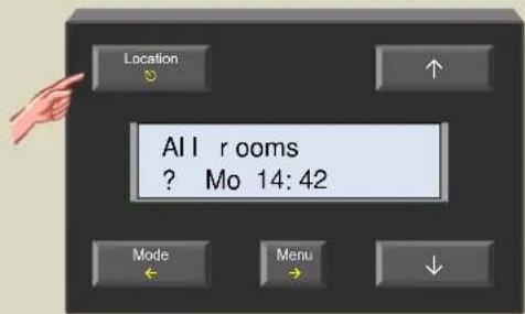
- Press and hold the 'Menu' button for ±4 seconds to open the extended menu.

- Scroll through the extended menu using the ↑ or ↓ button until the 'Sensor settings' item appears.
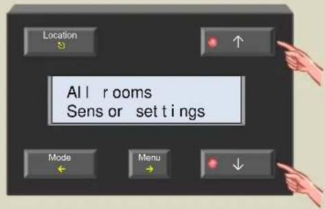
- Select the sensor settings menu with the → button.

- Scroll through the sensor settings menu using the ↑ or ↓ button until the 'Lower cool temp' item appears.

- Select the lower cool temp. menu with the → button.

- Set the lower cool temp. with the or button.

- Confirm with the → button.

- Exit the menu with the ⏻ button.

Maximum cooling temperature
This is the highest allowed room temperature. When temperature rises above the maximum cooling temperature, the air conditioner will switch on.
- Press the 'Location' button repeatedly until the desired sensor or zone for which the upper cool temperature will be set is displayed.

- Press and hold the 'Menu' button for ±4 seconds to open the extended menu.
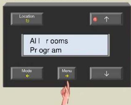
- Scroll through the extended menu using the ↑ or ↓ button until the 'Sensor settings' item appears.

- Select the sensor settings menu with the → button.

- Scroll through the sensor settings menu using the ↑ or ↓ button until the 'Upper cool temp' item appears.
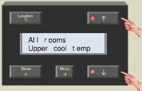
- Select the upper cool temp. menu with the → button.

- Set the upper cool temp. with the or button.

- Confirm with the → button.

- Exit the menu with the ⏻ button.

Hysteresis temperature
Hysteresis defines the difference between the on- and off temperature of the heating or air-conditioning.
- Press the 'Location' button repeatedly until the desired sensor or zone for which the hysteresis temperature will be set is displayed.
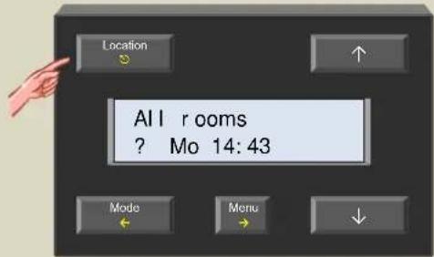
- Press and hold the 'Menu' button for ±4 seconds to open the extended menu.

- Scroll through the extended menu using the ↑ or ↓ button until the 'Sensor settings' item appears.
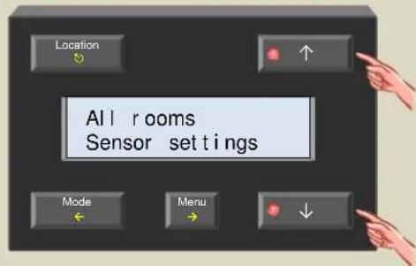
- Select the sensor settings menu with the → button.

- Scroll through the sensor settings menu using the ↑ or ↓ button until the 'Hysteresis' item appears.
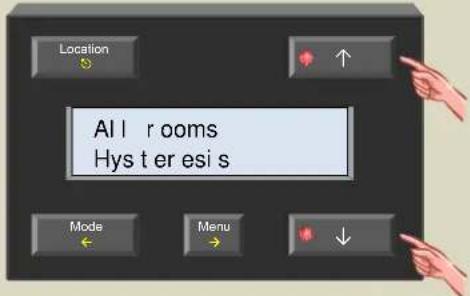
- Select the hysteresis menu with the → button.

- Set the hysteresis temperature with the or button.

- Confirm with the → button.

- Exit the menu with the ⏻ button.

Temperature difference
Convectors often have a built-in fan for faster heating. This setting determines how much the temperature needs to drop below the desired temperature in order to switch on the convectors' fan(s).
The temperature difference is also used for the differential thermostat (see paragraph on differential thermostat).
- Press the 'Location' button repeatedly until the desired sensor or zone for which the temperature difference will be set is displayed.

- Press and hold the 'Menu' button for ±4 seconds to open the extended menu.

- Scroll through the extended menu using the ↑ or ↓ button until the 'Sensor settings' item appears.

- Select the sensor settings menu with the → button.
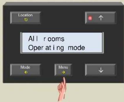
- Scroll through the sensor settings menu using the ↑ or ↓ button until the 'Temp difference' item appears.

- Select the temp. difference item with the → button.

- Change the difference temperature with the ↑ or ↓ button.

- Confirm with the → button.

- Exit the menu with the ⏻ button.

Difference sensor
Using two sensors a differential thermostat can be created. When the difference in temperature between both sensors reaches a certain value, a relay channel can be activated.
To achieve this, the one sensor must know the address of the other one (see paragraph on differential thermostat).
- Push the 'Location' button until the first sensor of the differential thermostat is displayed.
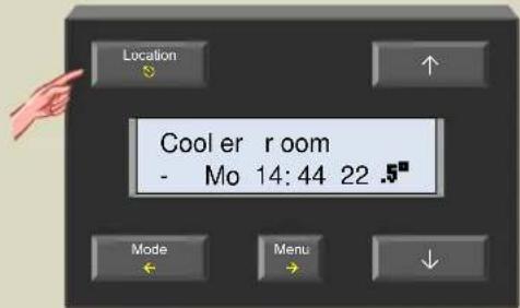
- Press and hold the 'Menu' button for ±4 seconds to open the extended menu.

- Scroll through the extended menu using the ↑ or ↓ button until the 'Sensor settings' item appears.

- Select the sensor settings menu with the → button.

- Scroll through the sensor settings menu using the ↑ or ↓ button until the 'Diff. Sensor' item appears.

- Select the diff. sensor item with the → button.

- Select the second sensor of the differential thermostat using the or button.

Remark:
If no differential thermostat is needed, the entry field must remain empty ('---').
- Confirm with the → button.

- Exit the menu with the ⏻ button.
Protecting the circulation pump
When a circulation pump is not being used for some time, it might get stuck. To avoid this, an unjamming function can be enabled which activates the pump for at least one minute every day.
- Press the 'Location' button repeatedly until the desired sensor or zone for which the pump unjamming function will be set is displayed.

- Press and hold the 'Menu' button for ±4 seconds to open the extended menu.

- Scroll through the extended menu using the ↑ or ↓ button until the 'Sensor settings' item appears.
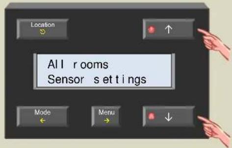
- Select the sensor settings menu with the → button.

- Scroll through the sensor settings menu using the ↑ or ↓ button until the 'Unjam pump' item appears
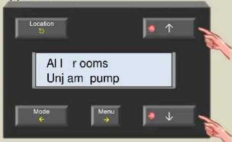
- Select the unjam menu with the → button.

- Switch unjam on or off with the ↑ or ↓ button.

- Confirm with the → button.

- Exit the menu with the ⏻ button.
Protecting the valves
To avoid valves getting stuck, an unjam function is available. This function will open the valves for at least one minute every day
- Press the 'Location' button repeatedly until the desired sensor or zone for which the valve unjamming function will be set is displayed.

- Press and hold the 'Menu' button for ±4 seconds to open the extended menu.
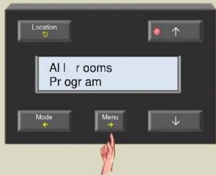
- Scroll through the extended menu using the ↑ or ↓ button until the 'Sensor settings' item appears.

- Select the sensor settings menu with the → button.

- Scroll through the sensor settings menu using the ↑ or ↓ button until the 'Unjam valve' item appears.

- Select the unjam menu with the → button.

- Switch unjam on or off with the ↑ or ↓ button.

- Confirm with the → button.

- Exit the menu with the ⏻ button.

Calibrating the sensor
When the read temperature does not match the real measured value on a thermometer, the read temperature can be corrected
- Press the 'Location' button repeatedly until the desired sensor that needs calibration is displayed.

- Press and hold the 'Menu' button for ±4 seconds to open the extended menu.

- Scroll through the extended menu using the ↑ or ↓ button until the 'Sensor settings' item appears.
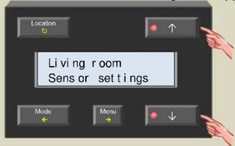
- Select the sensor settings menu with the → button.

- Scroll through the sensor settings menu using the ↑ or ↓ button until the 'Temp calibration' item appears.

- Select the calibration menu with the → button.
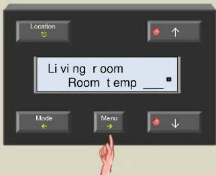
- Enter the temperature as measured with a different thermometer using the or button.
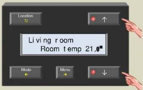
- Confirm with the → button.
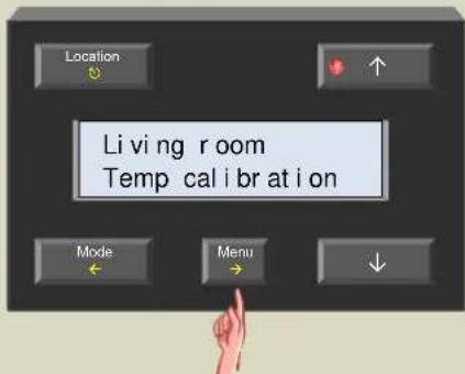
- Exit the menu with the ⏻ button.

Verify whether the controller contains the latest firmware by examining the firmware version.
If the Velbus installation contains an interface (VMB1USB, VMB1RS or VMBRSUSB) the controller firmware can be updated when necessary.
Remark:
Upgrading a module is not without risk. Do not interrupt the process!
If for any reason the upgrade should fail, the module will cease normal operation. The module will have to be returned to the manufacturer.
- Press and hold the 'Menu' button for ±4 seconds to open the extended menu.

- Scroll through the extended menu using the ↑ or ↓ button until the 'Configuration' item appears.

- Select the configuration menu with the → button.

- Scroll through the configuration menu using the ↑ or ↓ button until the 'Firmware version' item appears.

- Select the firmware version menu with the → button. Remember the version number.

- Exit the menu with the ⏻ button.
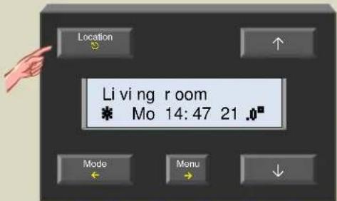
- Check http://www.velbus.eu whether you have the latest version.
If a newer version is available, download it.
Connect the Velbus interface to a PC and run the upgrade-software.
Follow the instructions on the screen.
PIN CODE PROTECT THE EXTENDED MENU
Default any user can access the extended menu. To avoid unauthorized users making changes in the extended menu, restrict access by setting a PIN code.
- Press and hold the 'Menu' button for ±4 seconds to open the extended menu.

- Scroll through the extended menu using the ↑ or ↓ button until the 'Configuration' item appears.

- Select the configuration menu with the → button.
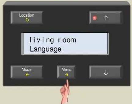
- Scroll through the configuration menu using the ↑ or ↓ button until the 'Change PIN code' item appears.
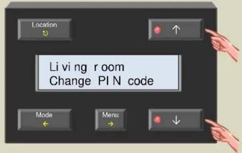
- Select the change PIN code menu with the → button.
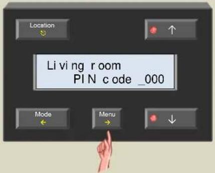
- Change the first number of the PIN code with the ↑ or ↓ button and confirm with the → button.

- Change the second number of the PIN code with the ↑ or ↓ button and confirm with the → button.
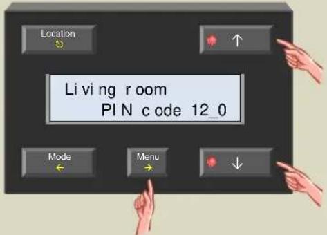
- Change the third number of the PIN code with the ↑ or ↓ button and confirm with the → button.
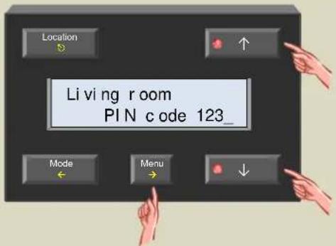
- Change the last number of the PIN code with the ↑ or ↓ button and confirm with the → button.
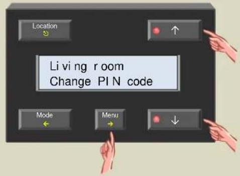
10.Exit the menu with the Ⓧ button.
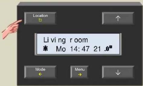
When the PIN code is not '0000', the extended menu can only be accesses after enter the correct PIN code.
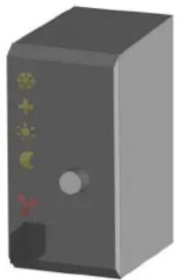
Anti-freeze, night, day or comfort mode indication
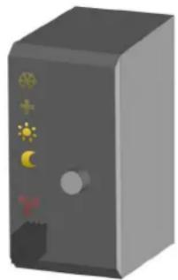
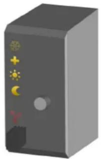
In rooms that have a temperature sensor VMB1TS the heating (or air-conditioning) can be set in 4 different modes: comfort, day, night or anti-freeze. Every mode has its own desired temperature setting.
The selected mode is indicated with LEDs.
The sensor module is set to anti-freeze mode when the comfort, day and night mode LEDs are off.
When the comfort, day or night mode LED is flashing, the sensor module is set temporarily (sleep timer) to the indicated mode and normal program is suspended during that 'sleep' time.
Anti-freeze
natural_image
3D rendering of a gray server or device casing with no visible text or symbolsNight

natural_image
3D rendering of a gray server or device with a black door and control buttons (no visible text or symbols)Day
natural_image
3D rendering of a gray server or device with five colorful icons on its side (no text or symbols)Comfort
natural_image
3D rendering of a gray server or control unit with five colorful icons on its side (no text or symbols)Cooling or heating mode indication
When the temperature sensor is configured to control an air-conditioning system, the frost flower LED (upper LED) will be lit.
Setting the heating or cooling mode can only be done through a temperature controller (VMB1TC) or through the Velbus link program.
Heating mode Cooling mode

natural_image
3D rendering of a gray server or device casing with five yellow-green buttons and red buttons on the side (no text or symbols visible)
natural_image
3D rendering of a gray server or device with indicator lights and ports (no text or symbols visible)Air-conditioner or heater active indication
When the heater (valve open) or air-conditioner is active, a red LED will be lit.

natural_image
3D rendering of a gray server or device with indicator lights and ports (no text or symbols visible)The red output LED can indicate following error conditions:
- Flashing (short on, long off): the heater/cooler should be off but it did not receive the command from the relays module.
- Flashing (short off, long on): the heater/cooler should be on but it did not receive the command from the relays module.
- Fast flashing: configuration of the sensor chip failed.
Note: as long as the error condition exists the output status will be re-transmitted every minute.
Operation
Pushing the push button repeatedly will switch the module between anti-freeze, night, day or comfort mode successively.

natural_image
Illustration of a hand pointing at a server rack with connectors and a green circuit board (no text or symbols visible)When the comfort, day or night mode LED is flashing, the sensor module is set temporarily (sleep timer) to the indicated mode. During this time the program is ignored
When the sleep timer expires, the sensor module will resume the program or in case no program is present will return to its previous setting.
Remarks:
- Anti-freeze mode can not be set temporarily.
- Standard time is set through the temperature controller.
- Overriding temporary mode can be done by pushing and holding the push button. The LED stops flashing and the sensor remains in the selected mode until the next program step is executed.
- Local operation can be locked or unlocked via a temperature controller VMB1TC or via the Velbus link program.
- When the sensor module is set to manual mode via a temperature controller VMB1TC or via the Velbus link program, local operation will be locked.
Select room or zone
To set up a heating system for different rooms, each room will need a temperature sensor. Multiple rooms can be grouped together in zones (e.g. ground floor, second floor, bedrooms...).
Prior to setting heating (or air-conditioning) requirements for a certain room or zone, the desired room or zone must be selected on the controller.
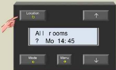
Press the 'Location' button repeatedly until the desired room or sensor is displayed.

Remark:
Press and hold the 'Location' button for fast switching between rooms and zones.


The previous/next room or zone can be selected with the “↑” or “↓” button as long as the LED of these buttons blinks.

Recall and change the desired temperature
At any time the desired temperature for a room can be shown and/or changed.
- Press the or button.
The desired temperature for the selected room is flashing on the display.
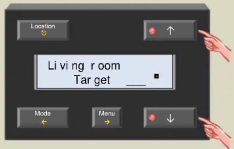
- When desired, change the target temperature with the or button.
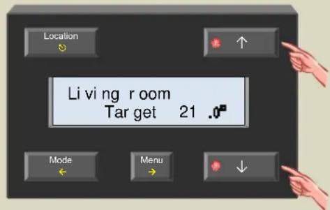
- Return to normal display by pressing the ☑ or ← button or simply wait for ±5 seconds without touching any button.
Remark:
When switching between anti-freeze, night, day or comfort mode the target temperature will be replaced by the desired temperature that is linked to each mode.
Temporarily switching between comfort, day, night or anti-freeze mode
In rooms equipped with a temperature sensor VMB1TS, the heating (or cooling) can be set to 4 modes (comfort ✦, day ✦, night ✦ or anti-freeze - ). Every mode has a preferred temperature setting.
The heating (or cooling) can be forced temporarily (sleep timer) into a certain mode. During that time, all program instructions will be ignored. Once the timer expires the normal program is resumed or when no program was active the device returns to the previous mode.
This could be useful e.g. to switch the heating of the bathroom to comfort mode for an hour.
Temporarily switching between the different modes is done by pushing the push button on the temperature sensor VMB1TS or via this module.
When a room is selected on the controller the heating (or cooling) mode can be adjusted.
When a zone is selected on the controller the heating (or cooling) mode of all rooms that belong to that zone will be adjusted.
1. First select the desired room or zone with the 'Location' button

- Press the 'Mode' button (bottom left) multiple times until the desired mode (- ☒, ☒☒, *☒ or ⌘☒) is displayed.

To indicate that temporary mode (sleep timer) is enabled, the LED on the 'Mode' button starts flashing and the display shows an hourglass. The indication LEDs on the sensor module also will flash.
The remaining time of the sleep timer is shown on the display except when a zone was selected.
symbol mode


?
Temporarily in anti-freeze mode
Temporarily in night mode
Temporarily in day mode
Temporarily in comfort mode
The mode is not the same for every room inside the zone
Remark:
Temporary mode (sleep timer) can be cancelled by pushing and holding the 'Mode' button until the hourglass is not longer shown on the display.
The chosen mode remains active until the next program instruction.
Setting the sleep time (temporary mode)
Once the heating (or air-conditioning) is in temporary mode, the duration of the sleep timer can be increased or decreased. This could be useful e.g. to leave the heating in comfort mode a few hours longer.
- If sleep timer is active, press the 'Menu' button.

- The 'Sleep timer' menu appears on the display. Select the item with the → button.

- The remaining sleep timer-time flashes on the display. Change the time with the ↑ or ↓ button.

- Confirm the changes with the → button.

Remark:
Cancel the changes by pressing the ← button in stead of the → button.
- Exit the menu with the ⏻ or ← button.
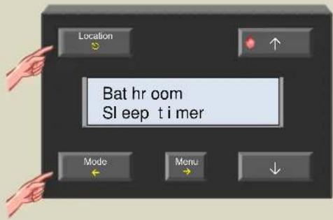
Remark:
It is also possible to exit the 'Sleep timer' menu by pressing the ↑ button until the 'Exit' item appears. Select this item with the → button.
Holiday setting
When going on a holiday trip, the heating should be set to anti-freeze or night mode and a sleep timer should be configured. As long as the sleep timer is running, all program instructions are ignored. Once the sleep timer is finished, normal operation is resumed.
- Select 'All rooms' with the 'Location' button.

- Set the heating (or AC) to anti-freeze or night mode using the 'Mode' button.

- Press the 'Menu' button.

- Select the sleep timer item with the → button.

- Set the number of holidays with the ↑ or ↓ button.
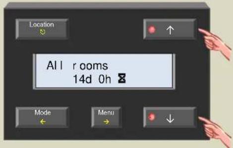
- Confirm the set time period with the → button.

- Exit the menu with the ⏻ or ← button.

To cancel the holiday program, press and hold the 'Mode' button until the hourglass symbol (☒) disappears.
Summer setting
During summer time the heating should be set in anti-freeze mode. All program instructions are ignored for an undefined time period.
- Select 'All rooms' with the 'Location' button.

- Set the heating to anti-freeze mode using the 'Mode' button.

- Press the 'Menu' button.

- Select the sleep timer item with the → button.

- Set the sleep time to 'Manual' with the ↑ or ↓ button.
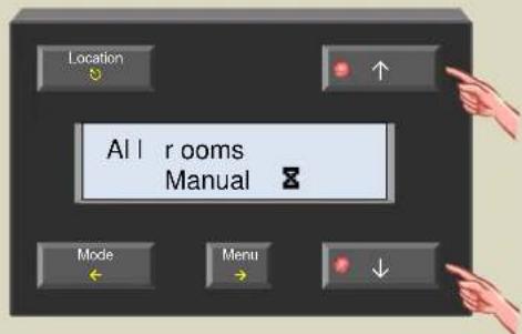
- Confirm the manual setting with the → button.

- Exit the menu with the ⏰ or ← button.

The key symbol (ī) confirms manual mode.
To cancel the summer program, press and hold the 'Mode' button until the key symbol (☐) disappears.
Setting the comfort, day and night temperature
The temperature sensor VMB1TS can be used in 4 modes (comfort ✗, day ✗, night ⬇ or standby - ). Every mode has its own preset for the desired temperature.
- Press the 'Location' button repeatedly until the desired room or zone for which one wants to set the preferred comfort, day and/or night temperature is displayed.
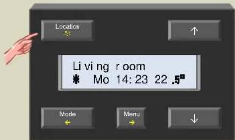
- Press the 'Menu' button to open the menu.

- Select the temperature settings menu with the → button.

- Select the comfort item with the → button. The desired comfort temperature starts flashing.

- Set the desired comfort temperature with the ↑ or ↓ button.
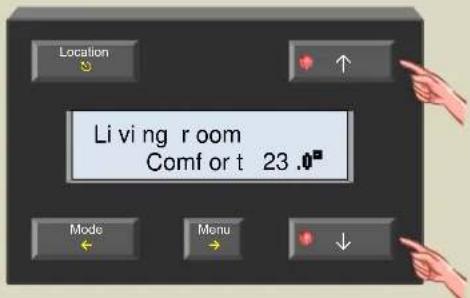
- Confirm with the → button.
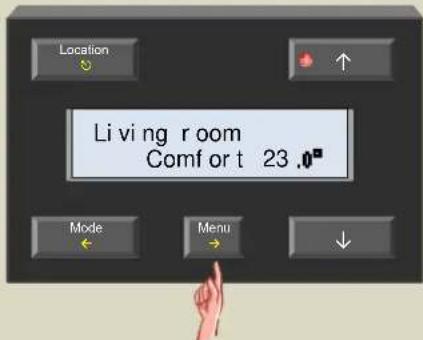
- Scroll to the day item with the ↑ button.
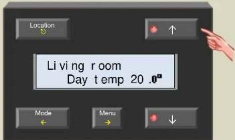
- Select the day item with the → button. The desired daytime temperature starts flashing.

- Set the desired day temperature with the ↑ or ↓ button.

- Confirm with the → button.

- Scroll to the night item with the ↑ button.
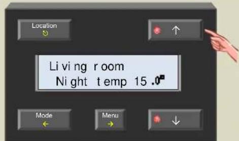
- Select the night item with the → button. The desired night time temperature starts flashing.

- Set the desired night temperature with the ↑ or ↓ button.

- Confirm with the → button.

- Scroll to the 'To main menu' item with the ↑ button.
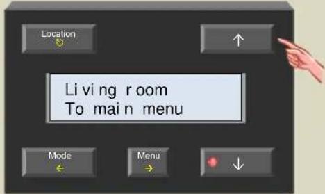
- Return to the main menu by pressing the → button.

- Exit the menu with the ⊙ or ← button.

Note: In the sensor settings menu, it is possible to adjust the temperature limits.
STATISTICS
For every temperature sensor the minimum and maximum temperatures can be recalled as well as the time during which the heating or air-conditioning was in a certain mode (comfort, day, night or anti-freeze) and how long it was active.
Requesting statistics
- Press the 'Location' button repeatedly until the desired room or sensor is displayed.
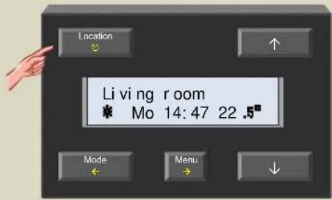
- Press and hold the 'Menu' button for ±4 seconds to open the extended menu. Enter the PIN code if necessary.

- Scroll through the extended menu using the ↑ or ↓ button until the 'Statistics' item appears.

- Select the statistics menu with the → button. The display shows the minimum temperature.
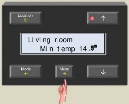
- Press the ↑ button to see the maximum temperature.
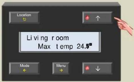
- Press the ↑ button. The first time indication shows how long the heating or AC was on during anti-freeze mode. The second time indication shows how long anti-freeze mode has been enabled.

- Press the ↑ button.
The first time indication shows how long the heating or AC was on during night mode.
The second time indication shows how long night mode has been enabled.

- Press the ↑ button.
The first time indication shows how long the heating or AC was on during day mode.
The second time indication shows how long day mode has been enabled.
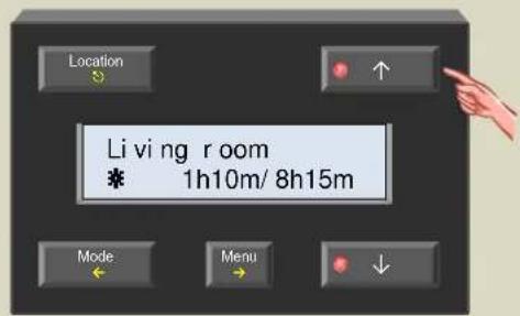
- Press the ↑ button.
The first time indication shows how long the heating or AC was on during comfort mode.
The second time indication shows how long comfort mode has been enabled.

- Press the ↑ button.
The first time indication shows how long the heating or AC was on in total..
The second time indication shows the total elapsed time since statistic registration started..

11.Exit the menu with the ⏻ button.

Reset statistics
Statistics registration can be reset individually.
- Press the 'Location' button repeatedly until the desired room of which the statistics must be reset is displayed.
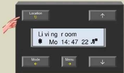
- Press and hold the 'Menu' button for ±4 seconds to open the extended menu. Enter the PIN code if necessary.

- Scroll through the extended menu using the ↑ or ↓ button until the 'Statistics' item appears.

- Select the statistics menu with the → button. The display shows the minimum temperature.

- Scroll through the statistics menu using the ↑ or ↓ button until the statistic appears that needs to be reset.

- Select the statistic with the → button. The statistics data starts flashing.

- Use the ↑ or ↓ button until horizontal lines are displayed in the data entry fields.

- Confirm the reset with the → button.

- Repeat steps 5 through 8 to reset the other statistics, or exit the menu using the Ⓧ button.
PROGRAM INSTRUCTIONS LOCATION
This chapter is only applicable when multiple temperature controllers are connected to your Velbus installation. It can be skipped if you have only one controller connected.
Prior to start programming it is important to determine which temperature controller will hold the program instructions for the rooms, zones and 'all rooms' to avoid that multiple controllers contain different instructions for the same rooms or zones.
The instruction set will be available from every controller.
- Determine the temperature controller that will hold the program instructions for a certain room or zone.
- On that controller, press the 'Location' button repeatedly until the desired room, zone or 'all rooms' is displayed.

- Press and hold the 'Menu' button for ±4 seconds to open the extended menu. Enter the PIN code if necessary.
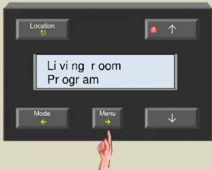
- Scroll through the extended menu using the ↑ or ↓ button until the 'Sensor settings' item appears.

- Select the sensor settings menu with the → button.

- Scroll through the sensor settings menu using the ↑ or ↓ button until the 'Local program' item appears.

- Select the local program menu with the → button.

- Switch on local program with the or button.
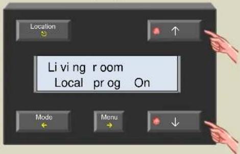
9. Confirm with the → button.
The living room program instructions will only be stored on this controller.
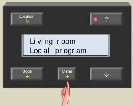
Remark:
If on another controller the location for the living room program instructions would be verified, it would show that the local program on that controller is off.
10.Exit the menu with the Ⓧ button.
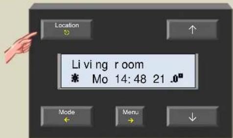
11. Repeat steps 1 through 10 for all other rooms and zones.
The controller can handle up to 32 temperature sensors VMB1TS. Every room that needs to be heated or cooled must have its own temperature sensor. These rooms can be divided over 7 zones if desired.
For every room or zone a program instruction set is available. There is also a program instruction set foreseen for all rooms together.
In every program a maximum of 31 instructions can be stored.
A program instruction consists of 3 parts:
1. The days on which the program instruction is applicable:
• Day program: every Monday, Tuesday, Wednesday, Thursday, Friday, Saturday or Sunday
• Working day program: from Monday to Friday (included) or from Monday to Saturday (included)
- Weekend program: every Saturday and Sunday
• Week program: every day
2. The exact time at which the instruction is to be executed:
- Exact indicated time
- The wake-up time plus or minus a certain time period
- The go-to-bed time plus or minus a certain time period
3. The mode to which the heating or air-conditioning should be set:
- Comfort mode
- Day mode
- Night mode
- Anti-freeze mode
Tips:
- Program instructions that are applicable for all rooms should be programmed under the ‘all rooms’ program. This way the instruction has to be entered only once in stead of for each room separately.
- The same goes for common program instructions that are valid for all rooms in the same zone. Select the zone on the controller and enter the program instruction into the zone program.
- Program instructions that are unique for a room must be entered into the program of that room.
- Consider using wake-up or go-to-bed times inside the program instructions. When a certain instruction needs to be carried out at a different time, only the wake-up or go-to-bed time needs to change, not the whole program.
For example, set the heating for bathroom, kitchen and living room in day mode half an hour before wake-up time; set the bathroom heating back to night mode 1 hour after wake-up time. If one feels like sleeping longer or getting up earlier, only changing the wake-up time is needed.
Remarks:
- As soon as a program is available for a certain room, a 'p' will appear on the display behind the mode symbol.

- When no sensor program is available, but there is a zone program, a 'z' will appear on the display behind the mode symbol.

- When no sensor or zone program is available, but there is an 'All rooms' program, an 'A' will appear on the display behind the mode symbol.
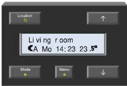
Overview program instruction
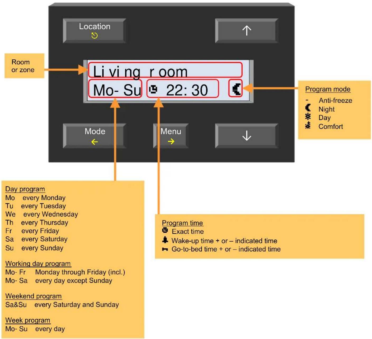
flowchart
graph TD
    A["Room or zone"] --> B["Living room"]
    B --> C["Mo- Su 22:30"]
    C --> D["Day program"]
    D --> E["Working day program"]
    E --> F["Weekend program"]
    F --> G["Week program"]
    style A fill:#f9f,stroke:#333
    style B fill:#ccf,stroke:#333
    style C fill:#cfc,stroke:#333
    style D fill:#fcc,stroke:#333
    style E fill:#ffc,stroke:#333
    style F fill:#cff,stroke:#333
    style G fill:#ffc,stroke:#333
Entering a new program instruction
- Press the 'Location' button repeatedly until the room or zone of which a program instruction needs to be added is displayed.

- Press and hold the 'Menu' button for ±4 seconds to open the extended menu. Enter the PIN code if necessary.

- Select the program menu with the → button. The display shows the first program instruction.

Remark:
When no instructions are entered yet, the line will be empty. Skip step 4 and proceed with step 5.
- Scroll through the program instructions using the ↑ button until the instruction line is empty.
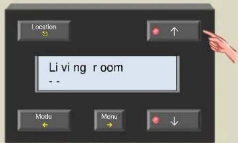
- Press the → button to add an instruction. The first data entry field flashes.

- Use the ↑ or ↓ button to set the day(s) on which the instruction needs to be executed. Confirm with the → button.
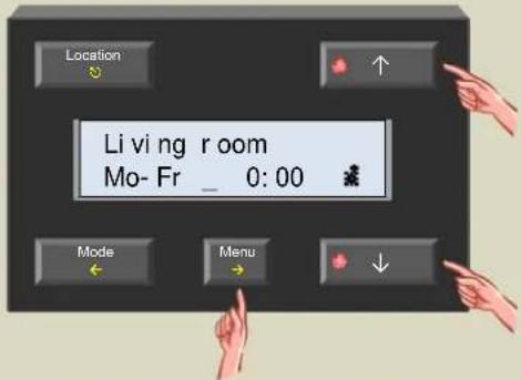
- Use the ↑ or ↓ button to set the time reference (exact, relative to wake-up or go-to-bed time) on which the instruction needs to be executed. Confirm with the → button.
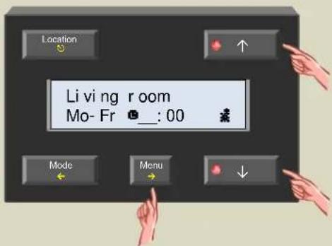
- Change the program time with the ↑ or ↓ button and confirm with the → button.

Remark:
In case the wake-up or go-to-bed time is selected as reference, the offset can be set per 15 minutes with a limit of 4 hours. Step 9 is not applicable.
- Set the minutes using the ↑ or ↓ button and confirm with the → button.

- Set the mode (comfort, day, night or anti-freeze mode) with the ↑ or ↓ button and confirm with the →button.
The flashing cursor disappears.

- Repeat steps 4 through 10 to add more program instructions or exit the menu using the Ⓧ button.
Changing a program instruction
- Press the 'Location' button repeatedly until the room or zone of which the program instruction needs to be changed is displayed.

- Press and hold the 'Menu' button for ±4 seconds to open the extended menu. Enter the PIN code if necessary.

- Select the program menu with the → button. The display shows the first program instruction.

- Scroll through the program using the ↑ or ↓ button until the instruction that needs to change is shown.
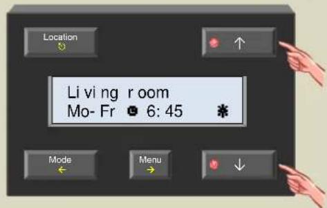
- Select the instruction that needs to change with the → button. The first data entry field flashes.
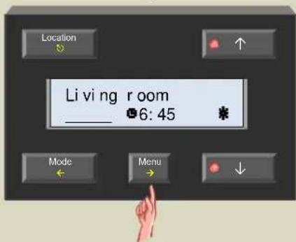
- Use the ↑ or ↓ button to set the day(s) on which the instruction needs to be executed. Confirm with the → button.

- Use the ↑ or ↓ button to set the time reference (exact, relative to wake-up or go-to-bed time) on which the instruction needs to be executed. Confirm with the → button.
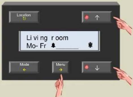
- Change the program time with the ↑ or ↓ button and confirm with the → button.

- Set the mode (comfort, day, night or anti-freeze mode) with the ↑ or ↓ button and confirm with the →button.
The flashing cursor disappears.
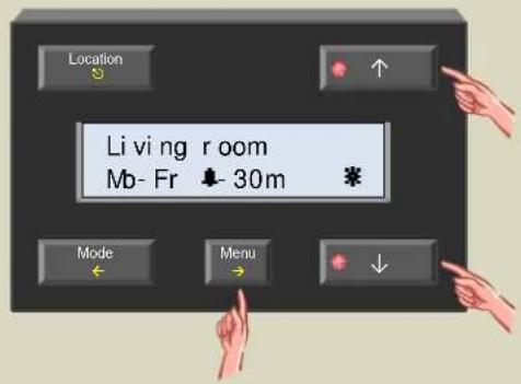
- Repeat steps 4 through 9 to change other program instructions or exit the menu using the Ⓧ button.
Removing a program instruction
- Press the 'Location' button repeatedly until the room or zone of which the program instruction needs to be changed is displayed.
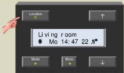
- Press and hold the 'Menu' button for ±4 seconds to open the extended menu. Enter the PIN code if necessary.
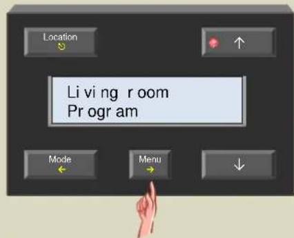
- Select the program menu with the → button. The display shows the first program instruction.
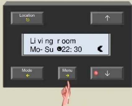
- Scroll through the program using the or button until the instruction that needs to be removed is shown.

- Select the instruction that needs to be deleted with the → button. The first data entry field flashes.

- Use the ↑ button until the instruction line is empty.

- Confirm with the → button. The program instruction is removed from the memory, the flashing cursor disappears and the next program instruction is shown. If this was the last instruction, the display remains empty.
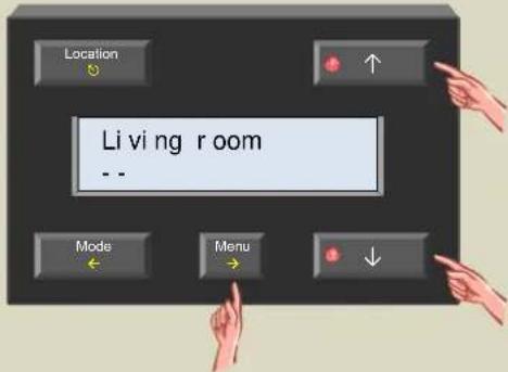
- Repeat steps 4 through 7 to remove other program instructions or exit the menu using the Ⓧ button.
DIFFERENTIAL THERMOSTAT
Using two sensors, a differential thermostat can be created. When the temperature difference between both sensors crosses a preset value, a relay channel can be activated.
To achieve this, the first sensors must know the address of the second one. The second sensor must than be linked to a relay channel. The temperature difference value is set on the first sensor.
To create a differential thermometer the set temperature difference is added to (or subtracted from) the measured temperature of the first sensor and this value is than sent every 6 seconds as desired temperature to the second sensor.
The settings can be done via a temperature controller VMB1TC or via the Velbus link program
Schematic overview differential thermostat (sensor2 in heating mode):
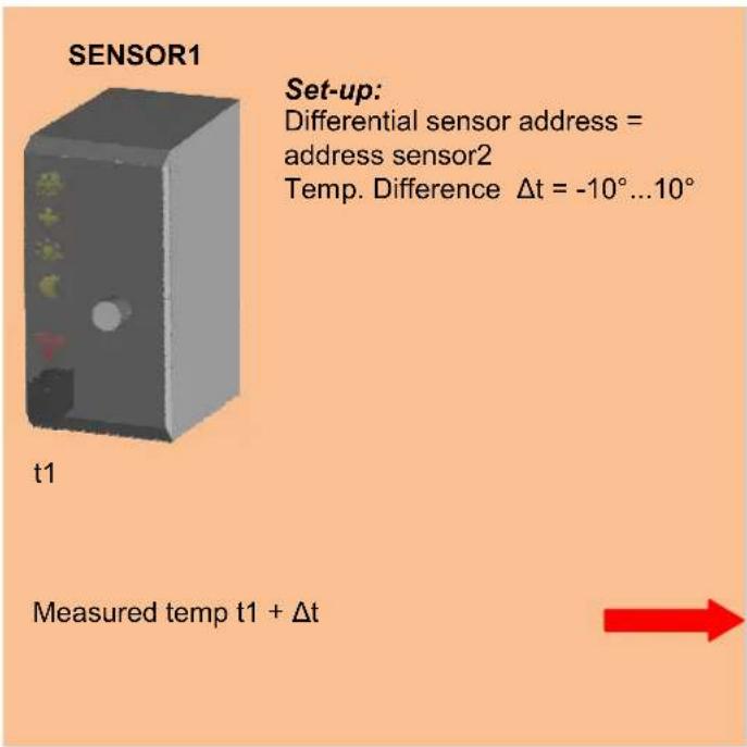
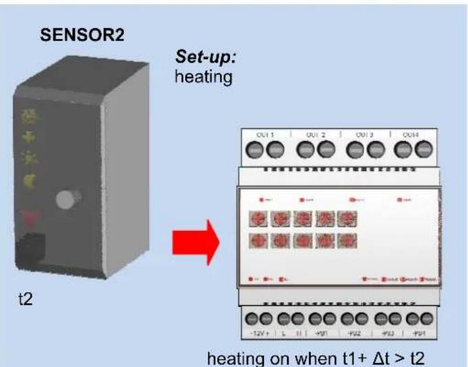
= Desired temperature for sensor2
Remark:
if t1 + Δt > tmode2 than desired temp. sensor2 = tmode2
(mode2 = anti-freeze, night, day or comfort)
Schematic overview differential thermostat (sensor2 in cooling mode):


Refer to some applications of a differential thermostat below.
The passage automatically 3° cooler than the office
When the sensor module in the office is set to day-mode, the temperature in the passage must be 3irc lower than the office. Is the day temperature of the office is set to 20irc C the desired passage temperature will be 17irc C. When the sensor module in the office is set to night-mode, the temperature in the passage must be 3irc lower than the office. Is the night temperature of the office is set to 15irc C the desired passage temperature will be 12irc C.

flowchart
graph TD
    subgraph Office
        A["Device 1"] --> B["Control Panel"]
        C["Device 2"] --> B
        D["Device 3"] --> B
        E["Device 4"] --> B
        F["Device 5"] --> B
        G["Device 6"] --> B
    end
    subgraph Passage
        H["Device 7"] --> I["Control Panel"]
        J["Device 8"] --> I
        K["Device 9"] --> I
        L["Device 10"] --> I
        M["Device 11"] --> I
    end
    Office <--> Passage
Configuration:
The easiest way to configure the system is to use the Velbus link program via a PC connected on the Velbus PC interface (VMB1USB, VMB1RS of VMBRSUSB).
However, configuration can also be done without the aid of a computer. Refer to the procedure below.
Link the heating output of the office sensor to a relay channel (ex. channel1).
- Set the office sensor module in anti-freeze mode by pressing the push button on the front panel repeatedly until all LEDs are off.

natural_image
Illustration of a hand pressing a button on a computer tower with visible wiring (no text or symbols)-
Set the MODE and TIME1 rotary switches for channel 1 of the second relay module to '0' (instant control).
-
Remember the address of this relay module to reinstate it later on.
-
Set the address of the relay module to 'C1'. The 'MODE 1' LED flashes to indicate push button learning mode (PBM).

- Press and hold the lowest push button (HEAT) of the office sensor until the relay is energised and the red LED on the sensor module flashes.
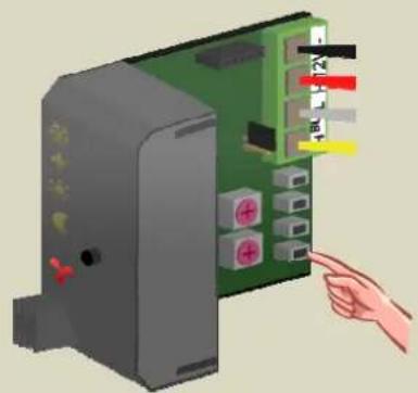
natural_image
Illustration of a computer interface with a hand pointing to the button (no text or symbols visible)- Set the address of the relay module back to its original value.
Use the relay channel (ex. channel1) to control the valve of the office radiator.
Link the heating output of the passage sensor to another relay channel (ex. channel2).
- Set the passage sensor module in anti-freeze mode by pressing the push button on the front panel repeatedly until all LEDs are off.

natural_image
Illustration of a hand interacting with an electronic device panel, showing ports and wiring (no text or symbols visible)-
Set the MODE and TIME1 rotary switches for channel 2 of the second relay module to '0' (instant control).
-
Remember the address of this relay module to reinstate it later on.
-
Set the address of the relay module to 'C2'. The 'MODE 2' LED flashes to indicate push button learning mode (PBM).
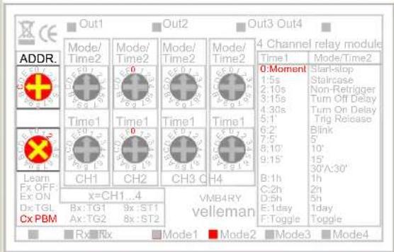
- Press and hold the lowest push button (HEAT) of the passage sensor until the relay is energised and the red LED on the sensor module flashes.
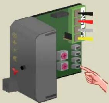
natural_image
Illustration of a hand pointing at a green circuit board with labeled pins (no text or symbols present)- Set the address of the relay module back to its original value.
Use this relay channel (ex. Channel2) to control the valve of the passage radiator.
- Press the 'Location' button until 'Office' is displayed.

- Press and hold the 'Menu' button for ±4 seconds to open the extended menu.

- Scroll through the extended menu using the ↑ or ↓ button until the 'Sensor settings' item appears.
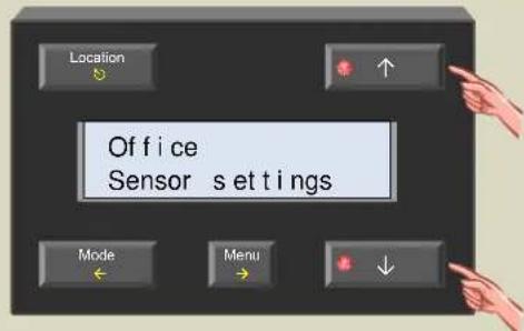
- Select the sensor settings menu with the → button.

- Scroll through the sensor settings menu using the ↑ or ↓ button until the 'Diff. sensor' item appears.
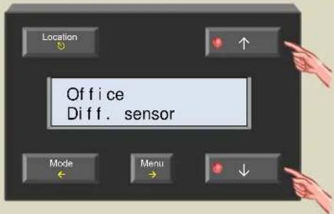
- Select the diff. sensor item with the → button.

- Select the sensor in the passage (to set up the differential thermostat) with the or button.
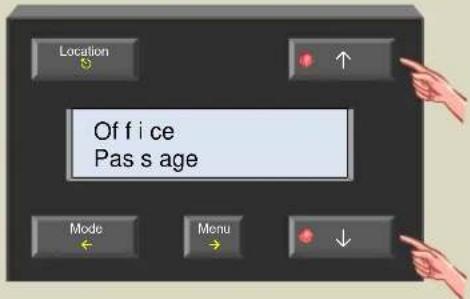
- Confirm with the → button.

- Scroll through the sensor settings menu using the ↑ or ↓ button until the 'Temp difference' item appears.

- Select the temp. difference item with the → button.

- Set the Temp diff. to -3irc using the or button.

- Confirm with the → button.

25.Exit the menu with the ⏻ button.
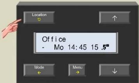
The configuration is now finished and the differential thermostat is enabled.
Remarks:
- Make sure both sensors are in heating mode (frost flower LED on the sensor is off).
- The passage temperature can never be higher than the preferred setting of its selected mode (anti-freeze, night, day or comfort).
Passive cooling of a bedroom
During summer time the bedroom is cooled via a fan that extracts air from a cooler room.
Mount a temperature sensor in both rooms. The temperature sensor of the bedroom is set to cooling mode and the cooling output is linked to a relay channel that controls the fan.
When the temperature in the cooler room is about 3 degrees lower than the bedroom temperature the fan is activated.

flowchart
graph TD
    A["Cooler room"] -->|Flow| B["Bedroom"]
    B -->|Flow| A
    style A fill:#f9f,stroke:#333
    style B fill:#bbf,stroke:#333
Configuration:
The easiest way to configure the system is to use the Velbus link program via a PC connected on the Velbus PC interface (VMB1USB, VMB1RS of VMBRSUSB).
However, configuration can also be done without the aid of a computer. Refer to the procedure below.
Link the cooling output of the bedroom sensor to a relay channel (ex. channel1).
- Set the bedroom sensor module in anti-freeze mode by pressing the push button on the front panel repeatedly until all LEDs are off.

natural_image
Illustration of a hand pointing at a server tower with visible wiring and connectors (no text or symbols)-
Set the MODE and TIME1 rotary switches for channel 1 of the second relay module to '0' (instant control).
-
Remember the address of this relay module to reinstate it later on.
-
Set the address of the relay module to 'C1'. The 'MODE 1' LED flashes to indicate push button learning mode (PBM).

- Press and hold the highest push button (COOL) of the bedroom sensor until the relay is energised and the red LED on the sensor module flashes.

natural_image
Illustration of a hand inserting a green circuit board into a device (no text or symbols visible)- Set the address of the relay module back to its original value.
Use the relay channel (ex. Channel2) to control the fan.
Set the difference sensor and difference temperature on the sensor of the cooler room via the temperature controller
- Press the 'Location' button until 'Cooler room' is displayed.

- Press and hold the 'Menu' button for ±4 seconds to open the extended menu.

- Scroll through the extended menu using the ↑ or ↓ button until the 'Sensor settings' item appears.

- Select the sensor settings menu with the → button.

- Scroll through the sensor settings menu using the ↑ or ↓ button until the 'Diff. sensor' item appears.

- Select the diff. sensor item with the → button.

- Select the bedroom sensor (to set up the differential thermostat) using the ↑ or ↓ button.

- Confirm with the → button.
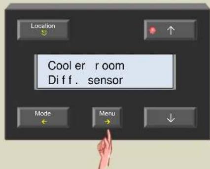
- Scroll through the sensor settings menu using the ↑ or ↓ button until the 'Temp difference' item appears.

- Select the temp. difference item with the → button.
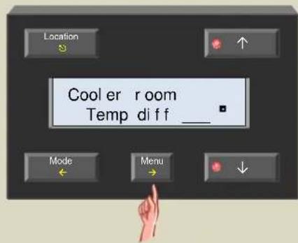
- Set the Temp. diff to 3° using the ↑ or ↓ button.

- Confirm with the → button.

19.Exit the menu with the ⏻ button.

- Press the 'Location' button until 'Bedroom' is displayed

- Press and hold the 'Menu' button for ±4 seconds to open the extended menu.
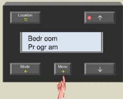
- Scroll through the extended menu using the ↑ or ↓ button until the 'Sensor settings' item appears.

- Select the sensor settings menu with the → button.
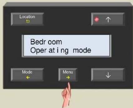
- Select the operating mode menu with the → button.

- Change the mode to cooling using the ↑ or ↓ button.

- Confirm with the → button.

27.Exit the menu with the Ⓧ button.
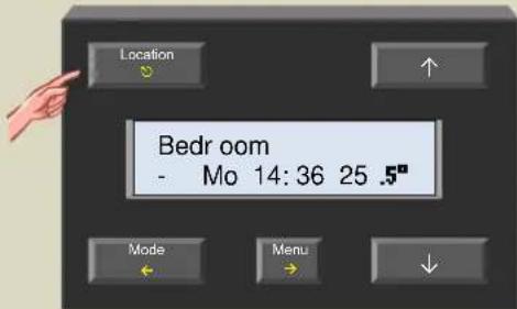
Set the sensor of the bedroom to comfort, day or night mode via the temperature controller
This can be done via the pushbutton on the bedroom sensor or via the mode pushbutton on the controller.

natural_image
Illustration of a hand pressing a button on a gray server cabinet (no text or symbols visible)
The configuration is now finished and the differential thermostat is enabled.
Remark:
The cooling will stop when the bedroom temperature reaches the preferred setting of its selected mode (night, day or comfort).

Refer to our website for more information: www.velbus.be



- VMB1TC
- Temperature control module for the Velbus system
- CONTENTS
- VERIFY SOFTWARE VERSION....68
- PIN CODE PROTECT THE EXTENDED MENU....69
- OPERATING THE TEMPERATURE SENSOR VMB1TS 71
- STATISTICS 81
- PROGRAM INSTRUCTIONS LOCATION 84
- PROGRAMMING 86
- DIFFERENTIAL THERMOSTAT....94
- DESCRIPTION
- CHARACTERISTICS
- LED indication
- LCD:
- Clock
- Local control
- Programming
- Power supply
- Dimensions
- The temperature controller module can transmit following messages:
- The temperature controller module can transmit following instructions:
- The temperature controller module can receive following messages:
- The temperature controller module can receive following instructions:
- EMBEDDING A TEMPERATURE SENSOR
- EMBEDDING A TEMPERATURE CONTROLLER TOGETHER WITH A SENSOR
- OVERVIEW HEATING INSTALLATION
- CONNECTION
- Connecting the temperature controller VMB1TC
- Connecting the temperature sensor VMB1TS
- Terminator
- Remark:
- Addressing
- Allocate the relay channels
- Allocate a relay channel to control valve 1
- Allocate a relay channel to control valve 2
- Allocate a relay channel to control valve 3
- Allocate a relay channel to control the fan
- Allocate a relay channel for day mode of the boiler
- Allocate a relay channel for the circulation pump
- BUTTON FUNCTIONS
- Location
- Mode
- Menu
- Direct access menu
- Extended menu
- Exit
- Note:
- Choice of language
- Temperature read-out (°Celsius or °Fahrenheit)
- Master clock
- Global alarm
- Battery backup
- Assign an action to the wake-up time
- Assign an action to the go-to-bed time
- Searching for temperature sensors
- Setting the clock
- Setting the alarm clock
- Disabling the alarm clock function
- Setting the display contrast
- Setting the backlight of the display
- Assign sensor names
- Defining zones
- Change the default zone names
- Heating or cooling mode
- Lock or unlock local mode setting
- Default duration of temporary mode (default sleep time)
- Low temperature alarm
- High temperature alarm
- Anti-freeze temperature
- Heating limit
- Minimum cooling temperature
- Maximum cooling temperature
- Hysteresis temperature
- Temperature difference
- Difference sensor
- Protecting the circulation pump
- Protecting the valves
- Calibrating the sensor
- PIN CODE PROTECT THE EXTENDED MENU
- Anti-freeze, night, day or comfort mode indication
- Cooling or heating mode indication
- Air-conditioner or heater active indication
- Operation
- Remarks:
- Select room or zone
- Recall and change the desired temperature
- Temporarily switching between comfort, day, night or anti-freeze mode
- First select the desired room or zone with the 'Location' button
- symbol mode
- Setting the sleep time (temporary mode)
- Holiday setting
- Summer setting
- Setting the comfort, day and night temperature
- STATISTICS
- Requesting statistics
- Reset statistics
- PROGRAM INSTRUCTIONS LOCATION
- Confirm with the → button.
- 10.Exit the menu with the Ⓧ button.
- Repeat steps 1 through 10 for all other rooms and zones.
- A program instruction consists of 3 parts:
- The days on which the program instruction is applicable:
- The exact time at which the instruction is to be executed:
- The mode to which the heating or air-conditioning should be set:
- Tips:
- Overview program instruction
- Entering a new program instruction
- Changing a program instruction
- Removing a program instruction
- DIFFERENTIAL THERMOSTAT
- The passage automatically 3° cooler than the office
- Configuration:
- Passive cooling of a bedroom
- Set the sensor of the bedroom to comfort, day or night mode via the temperature controller
Brand : Velbus
Model : VMB1TCW
Category : Thermostat