
N16NRD - Video camera Speco Technologies - Free user manual and instructions
Find the device manual for free N16NRD Speco Technologies in PDF.


| Product Type | IP Security Camera |
| Model | N16NRD |
| Brand | Speco Technologies |
| Resolution | 16 Megapixels (4K) |
| Image Sensor | 1/2.8" CMOS |
| Lens | 2.8-12mm motorized varifocal |
| Night Vision | IR LEDs up to 100ft |
| Video Compression | H.265+/H.265/H.264 |
| Field of View | 105° - 30° horizontal |
| Power Supply | 12V DC, PoE+ (802.3at) |
| Power Consumption | 12W max |
| Dimensions | 7.3 x 3.1 x 3.1 in (185 x 79 x 79 mm) |
| Weight | 1.5 lb (680 g) |
| Operating Temperature | -40°F to 140°F (-40°C to 60°C) |
| Weatherproof Rating | IP67 |
| Audio | Built-in microphone, line in/out |
| Analytics | Motion detection, line crossing, intrusion |
| Storage | MicroSD card slot (256GB max), NAS |
| Network | 10/100/1000 Mbps Ethernet |
| Compatibility | ONVIF Profile G, Q, T |
| Maintenance | Clean lens with soft dry cloth; keep firmware updated |
| Safety | Use only included power adapter; disconnect during cleaning |
| Spare Parts | Mounting bracket, screws, water-proof connector |
Frequently Asked Questions - N16NRD Speco Technologies
User questions about N16NRD Speco Technologies
0 question about this device. Answer the ones you know or ask your own.
Ask a new question about this device
Download the instructions for your Video camera in PDF format for free! Find your manual N16NRD - Speco Technologies and take your electronic device back in hand. On this page are published all the documents necessary for the use of your device. N16NRD by Speco Technologies.
USER MANUAL N16NRD Speco Technologies
Network Video Recorder User Manual
N8NRE/N16NRE/N32NRE
N16NRD
N4NRN/N8NRN/N16NRN/N32NRN
N4NRL/N8NRL
N8NRP/N16NRP
N64NR/N128NR
Rev. 12/20/2023
IMPORTANT
- Please read this user manual carefully to ensure proper and safe use of the equipment.
We are not responsible for technical errors or typos in this manual. The contents of this manual are subject to change without noce. - This device should only be operated only using the type of power source indicated on the rear panel. The voltage of the power supply must be veried before installing. It is recommended to disconnect from the power source if the device is not going to be used for a long period of me.
- Do not install this device near heat sources such as radiators, heang vents, stoves or other devices that produce heat.
- Do not install this device in a locaon at risk of water splash, drip, submersion, or high humidity. Clean only with a dry cloth.
● Never block any venlaon openings and always ensure proper venlaon around the machine.
● Always use the recorder menu opon to power o the device. - This recorder is for indoor use only. Do not expose the recorder to rain or a moist environment. If any solids or liquids get inside the recorder's chassis, please turn the device o immediately and get it checked by a qualified technician.
- Do not try to repair the device by yourself without technical aid or approval from Speco Technologies' Technical Support.
Contents
1 Introducon....1
1.1 Welcome .... 1
1.2 Features....1
1.3 Front Panel Descripons....3
1.4 Rear Panel Descripons .... 3
1.5 Connecons....3
2 Basic Operaon Guide 4
2.2 Remote Control 4
2.3 Mouse Control....5
2.4 Text-input Instruction 5
2.5 Common Buon Operation 6
3 EZ Setup & Main Interface 7
3.2 Main Interface....10
4 Camera Management 14
4.1 Add/Edit Camera 14
4.2 Add/Edit Camera Group....16
5 Live View Introducon....18
5.1 Live View Interface Introducon....18
5.2 View Mode....19
5.3 Image Conguraon 21
6 PTZ 26
6.1 PTZ Control Interface Introduction 26
6.2 Preset Settings 29
6.3 Cruise Sengs 30
6.4 Cruise Group Seings 31
6.5 Trace Sengs....31
6.6 Task Sengs 32
6.7 Smart Tracking....32
7 Record & Disk Management 34
7.1 Record Conguraon 34
7.2 Encode Parameters Sengs 37
7.3 Record Mode 38
7.4 Disk 38
8 Playback & Backup....43
8.2 Playback Interface Introducon 43
8.3 Smart Playback 45
8.4 Record Search, Playback & Export 49
9 AI Event Management 53
9.1 Face Recognition....53
9.2 License Plate Recognition 57
9.3 Line Crossing Detecon ....59
9.4 Intrusion Detecon....60
9.5 Abandoned/Missing Object Detecon....61
9.6 Crowd Density Detecon....62
9.7 Target Couning....62
9.8 Tampering Detecon 64
9.9 Fire Detecon 64
9.10 Temperature Detecon....65
9.11 Video Metadata (BETA)......66
10 Intelligent Analycs 67
10.2 Smart Search....71
10.3 View Stascal Information....78
10.4 Face Aendance 79
10.5 Face Check-In....80
11 General Event Management....82
11.2 Moon Alarm 82
11.3 Combinaon Alarm....83
11.4 IPC Oine Setngs 84
11.5 Excepon Alarm Sengs 84
11.6 Alarm Event Nocaon....84
11.7 Manual Alarm 88
11.8 View Alarm Status 88
11.9 System Disarming....88
12 Parking Lot Management....90
12.1 Parking Lot Sengs 90
12.2 Parking Lot Management....90
12.3 Search Vehicle Entry/Exing Records....91
13 Account & Permission Management 93
13.1 Account Management 93
13.2 User Login & Logout 95
13.3 Permission Management....95
13.4 Block and Allow List 96
13.5 Preview On Logout 96
13.6 Network Security 97
13.7 Password Security....97
13.8 View Online User 97
14 Device Management....98
14.1 Network Conguraon 98
14.2 Basic Conguraon....106
14.3 Factory Default 109
14.4 Device Soware Upgrade 109
14.5 Backup and Restore....110
14.6 Restart Automacally....110
14.7 View Log 110
14.8 View System Informaon....111
15 Remote Surveillance 112
15.2 Web LAN Access 112
15.3 Web WAN Access....112
15.4 Web Remote Control....113
Appendix A FAQ....119
Appendix B Calculate Recording Capacity 123
1 Introducon
1.1 Welcome
Thank you for purchasing this Speco Blue NVR.
If technical assistance is needed, please contact Speco Technologies Technical Support.
Phone: 1-800-645-5516 opon 3
Email: techsupport@specotech.com
1.2 Features
Basic Funcons
● Supports network device access including both Speco Technologies' and third-party IP cameras (IPC)
● This NVR supports the H.265 video coding stream and will also accept a mixed input of H.265 and H.264 IP cameras
● Supports standard ONVIF protocol
● Supports dual stream recording for each camera
● Supports the addition of IP cameras both automatically and manually
● Supports collective or individual conguraon of the cameras' OSD, video parameters, mask, moon, etc.
- Supports mulple smart detecon access and linkage for IPC's, such as scene change, video color cast detecon, video blur detecon, intrusion detecon (region entrance/exing detecon), target counting, abandoned object detecon, missing object detecon, crowd density detecon, face detecon, license plate detecon, smart tracking, re detecon, temperature detecon, video metadata (BETA), etc.
● Supports a maximum of 8 user permission groups. This includes Administrator, Advanced and Common, which are the default permission groups of the system.
● Supports the creation of a maximum of 16 users. Also supports mulple web client logins by using one username at the same me and the ability to enable or disable user permissions
● Supports mulple web client logins at the same me
- Live View
● Supports 4K×2K/1920×1080/1280×1024 HDMI and 1920×1080/1280×1024 VGA high-denion synchronous display
● Supports mul-screen modes such as 1 / 4 / 6 / 8 / 16 / 32 (varies by model)
- Supports auto adjustment of the camera's image display proportion
● Supports enabling or disabling audio monitoring of a camera
● Supports manual snapshot of a camera live view
● Supports camera sequence adjustment
● Supports adding and saving display modes, and saved modes can be recalled directly
● Supports quick tool bar operaon from the preview window
● Supports camera group view and scheme view in sequence, quick sequence view and dwell me setup
● Supports moon detecon and video masking
● Supports mulple popular PTZ control protocols and setup of preset and cruise
● Supports direct mouse control of the IP dome including rotang, zoom, focusing, etc.
● Supports the zoom of a single camera image by sliding the scroll wheel of the mouse
● Supports the zoom of any area of a camera image up to a maximum of 16 mes of the current size
● Supports image and lens adjustment (only available with some cameras)
● Supports quick camera addition in the camera window of the live view interface
- The live camera sequence of the web client will stay consistent with the NVR aer adjusng the live camera sequence of the NVR, but the live camera sequence of the NVR will not be changed if the web client is changed
- Disk Management
● Each SATA interface (varies by unit) on the NVR supports HDDs with a max storage capacity of 16TB
● Supports disk group conguraon and management and each camera can be added into dierent disk groups with dierent storage capacities
● Supports disk informaon and viewing of disk operang status
- Record Conguraon
● Supports simultaneous main stream and sub stream recording, as well as collective or individual conguraon of the recording stream
● Supports manual and auto recording modes
● Supports schedule recording, sensor alarm recording, moon detecon recording, etc.
● Supports schedule recording and event recording setup with dierent recording streams
● Supports recording schedule setup and recycle recording
● Supports pre-recording and delay recording conguraon of an event
- Record Playback
● Supports me scale operaon in quick playback and the playback date and me can be set randomly by scrolling the mouse; the me interval of the me scale can be zoomed
● Supports record searching by me slice/me/event/tag
● Supports me view and camera view in searching by EZ mode
● Supports EZ search by month, by day, by hour and by minute and me slice to be displayed with camera thumbnail
● Supports a maximum of 4/8/16 cameras to be searched at a me (varies by unit channel size)
● Supports event search by manual/moon/sensor/intelligent events
● Supports bookmark search by the manual added bookmarks
● Supports instant playback of the selected camera in the live view interface
● Supports a maximum of 8 synchronous playback cameras
● Supports acceleration (to a maximum 32 mes the normal speed), deceleration (to a minimum 1/32 mes the normal speed) and 30s addition or reduction to current playing me
- Record Export
● Supports export of a recording through USB (U disk, mobile HDD)
● Supports export of a recording by me/event/image search
● Supports record cung for exporng when playing back
● Supports a maximum of 10 export tasks in the background, as well as export status viewing
- Alarm Management
● Supports alarm schedule setup
● Supports enabling or disabling of the moon detecon, external sensor alarm input, intelligent alarm and excepon alarms including IP address conict alarm, disk IO error alarm, disk full alarm, no disk alarm, illegal access alarm, network disconncon alarm, IPC oine alarm and so on, alarm trigger conguraon supportable
● Supports IPC oine alarm trigger conguraon of PTZ, snapshot, pop-up video, etc.
● Supports event nocaon modes of alarm-out, pop-up video, pop-up message box, buzzer, e-mail and so on
● Captured images can be aached to an e-mail when alarm is triggered
● Supports alarm status view of alarm-in, alarm-out, moon detecon and excepon alarm
● Supports triggering and clearing an alarm manually
● Supports auto-reboot of the system when an excepon happens
● Supports face detecon and face match alarm
Face Funcon
● Supports adding 5,000 face pictures to the face database (up to 10,000 in select models)
● Supports image search by image, track playback and database management
● Supports face aendance and face check in
● Supports face informaon stascs
● Supports face match alarm
LPR Funcon
● Support registraon of up to 50,000 license plates
● Support license plate detecon, matching and search
● Support vehicle informaon stascs
● Support license plate match alarm
● Network Funcons
● Supports TCP/IP and PPPoE, DHCP, DNS, DDNS, UPnP, NTP, SMTP protocol and more
● Supports allow and block list funcon and the allow and block IP address/IP segment address can be set
● Supports multiple browsers including IE8/9/10/11, Firefox, Opera, Edge, Chrome (available only for the versions lower than 45) and Safari (on Macs)
● Supports remote conguraon, import and export of the NVR parameters and other system maintenance operations including remote upgrading and system restart
● Supports remote camera conguraon through the NVR including video parameters, image quality and so on
● Supports remote search, playback, and export through the NVR
● Supports triggering and clearing manual alarms remotely
● Motorized zoom cameras can be adjusted through the web client (Supports zoom in/out, but one key focus is not currently supported)
● Supports NVMS or other plaorm management soware to access the NVR and manage it
● Supports NAT funcon and QR Code scanning by mobile phone and PAD
● Supports mobile surveillance by phones or PADs with iOS or Android OS
● Supports access of the NVR remotely through telnet, and the telnet funcon can be enabled or disabled
- If one camera recording is enabled or disabled manually through the web client, it will be simultaneously enabled or disabled on the NVR
- Other Funcons
● The NVR can be controlled and operated by the buons on the front panel (on applicable models), the remote control and the mouse
- Setup interfaces can be conveniently switched by clicking the main menus at the top
● Supports NVR informaon viewing including basic, camera status, alarm status, record status, network status, disk and export status
● Supports factory restore, import and export of the system conguraon, log view and export and local upgrading by USB mobile device
● Supports auto recognition of the displayer's resolution
- You can click the right mouse button at any interface to go back to the upper interface
● You can click the mouse wheel at any interface to go to the live view interface
● The display language and video format of the NVR will not be changed and the system logs will be preserved if you reset the NVR to factory default
- Press and hold the right mouse buon for 5 seconds in any interface to switch the output to VGA and the NVR will display the video at the lowest resolution which the NVR supports
1.3 Front Panel Descripons
The following descripons are for reference only and may not apply to all models.
| Name | Descripons |
| REC | The light will be blue when recording |
| Net | The light will be blue when there is access to a network |
| Power | The light will be blue when there is power |
1.4 Rear Panel Descripons
To quickly get started, connect the items below to your recorder in the following order. Please refer to the following gure (N8NRE shown for reference).

- Connect IP cameras to the PoE ports of the recorder.
- Connect a monitor to the recorder via a VGA or HDMI cable (not included).
- Connect the included opcal mouse into any USB port of the recorder (front or rear).
- Connect the power adapter to the recorder and plug the power cord into a 120VAC 50/60Hz outlet.
- Connect recorder to network (oponal but needed for remote access or for access to cameras not directly connected)
- Turn on power switch and allow recorder to boot up.
1.5 Connecons
- Video Connecons
Video Output: Supports VGA/HDMI video output. You can connect to a monitor through these video output interfaces simultaneously or independently.
- Audio Connecons
Audio Input: Connect to microphone, pickup, etc.
Audio Output: Connect to headphone, powered speaker (ex, ASPC20), amplifier, or other audio output devices.
2 Basic Operaon Guide
2.1 Startup & Shutdown
Please make sure all connecons are done properly before you power on the unit. Proper startup and shutdown are crucial to extending the life of your device.
2.1.1 Startup
① Connect the output display device to the VGA/HDMI interface of the NVR.
② Connect the mouse and power. When powered on, the device will boot and the power LED would turn blue.
③ EZ setup window will pop up (you should select the display language the rst me you use the NVR). Refer to 3.1 EZ Setup for details.
2.1.2 Shutdown
You can power o the device by using remote control or mouse.
By remote control:
① Press Power buon. This will take you to a shutdown window. The unit will power o aer clicking "OK" buon.
② Disconnect the power.
By mouse:
① Click Start→Shutdown to open the Shutdown window. Select "Shutdown" in the window. The unit will power o aer clicking "OK" button.
② Disconnect the power.
2.2 Remote Control
① Uses two AAA size baeries. (Not included)
② Open the baery cover of the remote control.
③ Place baeries. Please note the polarity (+ and -) and insert properly.
④ Replace the baery cover.
Key points to check in case the remote doesn't work.
- Check your baeries polarity.
- Check the remaining charge in the batteries.
- Check IR controller sensor for any masking.
If it sll doesn't work, please contact your distributor.
Note that the remote control is the same for all units of the same model. Be sure to point the IR sensor of the remote control directly towards the IR receiver of the NVR you wish control if you have mulple devices. It's also recommended to place the recorders away from each other if possible.
There are two kinds of remote controllers. The interface is shown below.

| Buon | Funcon |
| REC | Record manually |
| Search | Enter search mode |
| MENU | Enter menu |
| Exit | Exit the current interface |
| ENTER | Conrm the choice or setup |
| Direcon buon | Move cursor in setup |
| ZOOM | Zoom in |
| P | Currently no funcon |
| Control playback. Play (Pause)/Next Frame/Speed Up/Stop/Previous Frame/Speed Down | |
| Mul | Choose mul screen display mode |
| Next | Switch the live image |
| SEQ | Go to sequence view mode |
| INFO | Get informaon about the device |

| Buon | Funcon |
| Turn device on and off | |
| Record Buon | Start recording |
| -/-- /0-9 | Input number or choose camera |
| Fn1 Buon | Currently no funcon |
| Mul Buon | Choose mul screen display mode |
| Next Buon | Switch the live image |
| SEQ | Go to sequence view mode |
| Audio | Enable audio output in live mode |
| Switch | Currently no funcon |
| Direcon buon | Move cursor in setup or pan/tle PTZ |
| Enter Buon | Conrm a choice or setup |
| Menu Buon | Go to menu |
| Exit Buon | Exit the current interface |
| Focus/IRIS/Zoom/PTZ | Control PTZ camera |
| Preset Buon | Enter preset sengs in PTZ mode |
| Cruise Buon | Go to cruise sengs in PTZ mode |
| Track Buon | Currently no funcon |
| Wiper Buon | Currently no funcon |
| Light Buon | Currently no funcon |
| Clear Buon | Currently no funcon |
| Fn2 Buon | Currently no funcon |
| Info Buon | Get informaon about the device |
| To control playback. Play (Pause)/Stop/Previous Frame/Next Frame/Speed Down/Speed Up | |
| Snap Buon | Take snapshots manually |
| Search Buon | Go to search mode |
| Cut Buon | Currently no funcon |
| Backup Buon | Go to backup mode |
| Zoom Buon | Zoom in |
| PIP Buon | Currently no funcon |
2.3 Mouse Control
Mouse control in Live Display & Playback interface
In the live display & playback interface, double click on any camera window to show the window in single screen mode; double click the window again to restore it to the previous size.
In the live display & playback interface, if the interfaces display in full screen, move the mouse to the top of the interface to have the tool bar appear. The tool bar will disappear automatically aer you move the mouse away from it; move the mouse to the right side of the interface to pop up a panel and the panel will disappear automatically aer you move the mouse away from it.
Mouse control in text-input
Move the mouse to the text-input box and then click the box. The input keyboard will pop up automatically.
Note: Mouse is the default tool for all operations unless an exception is indicated.
2.4 Text-input Instrucon

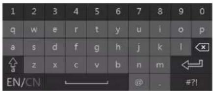
The interface has two types of input boxes. Refer to the above pictures. The le box is the number-only input box and the right box provides inputs of numbers, leers and punctuaon characters. The introducons of keys on the input boxes are shown below.
| Buon | Meaning | Buon | Meaning | |
 | Backspace key |  | Switch keyboard to see more punctuaon characters | |
 | Delete Key |  | Enter key | |
 | Switch between upper and lower case |  | Space key | |
 | Switch language | [2TK5] | ||
2.5 Common Buon Operaon
| Buon | Meaning | |||
 | Click to show the men |  | ||
| [DWRK] | ||||
 | Click to change the se | [68DZ] of the list. | ||
 | ||||
 | Click to change the ca | [7XX3] display mode. | ||
 | ||||
 | Click to close the curr | [X451] interface. | ||
 | Click to go to the earli |  face of camera recording. face of camera recording. | ||
 | Click to go to the lates |  of camera recording. of camera recording. | ||





3 EZ Setup & Main Interface
3.1 EZ Setup
The disk icons will be shown on the top of the startup interface. You can view the number and status of each disk quickly and conveniently through these icons (no disk; unavailable disk; RW available disk).
You can quickly congregate the NVR by clicking "OK" to begin the EZ Setup process. You must congregate the wizard if you start the NVR for the rst me (or click "Skip" to cancel the EZ Setup until the next me you login).
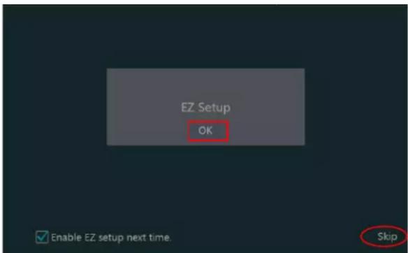
Click "OK" to start wizard. The setup steps are as follows:
① System Login. Set your own password when you use the wizard for the rst me (the default username of the system is admin); select the login username and enter a password.
Note: The default password level is "Strong". We highly recommend you create one with 8\~16 characters (including upper case leers, lower case leers, numbers and symbols) to increase the security of your product.
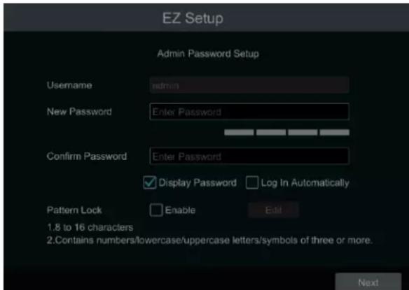
Click "Edit Security Queson" to set quesons and answers for admin password security. If you forget the password, please refer to Q4 in Appendix A FAQ for details.
Click "Next" to connue the wizard.
② Disk Sengs. You can view the disk number, disk capacity of the NVR and serial number, and R&W status of the disk. Click "Format" to format the disk. Click "Next" to connue. Then click "EZ Setup".
③ Network Sengs. Select the network parameters as required. Check "Obtain an IP address automacally" and "Obtain DNS automacally" to set the IP address and DNS automacally (the DHCP funcon of the router in the same LAN should also be enabled), or manually enter them. Enter the HTTP port, RTSP port and Server port (please see 14.1.2 Port Conguraon for details). Click "Next" to connue.

If you use the NVR with the PoE network ports, the online status of the internal Ethernet port will be shown on the interface. If the NVR has two or more network ports, you can select the network parameters as required. Network Fault Tolerance and Mulple Address seings are available.
④ Other Network Sengs.
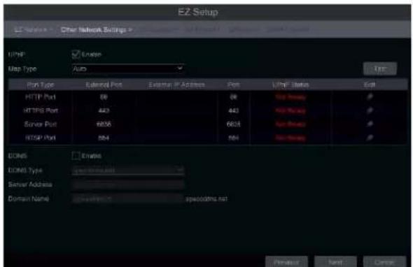
UPnP sengs: Check "Enable" in the interface and enter the external ports and then click "Test" to test the effectiveness of the input information. If the UPnP status states, "Invalid UPnP", the port number may be wrong. Click 📋 to modify the port until the UPnP status turns to "Valid UPnP". Refer to the picture below. If you know the external IP address of the NVR, enter the external IP address plus port in the address bar of your browser to access the NVR. (please see 14.1.6 UPnP Conguraon for details).
DDNS Sengs: Check "Enable" and then select the DDNS type. Enter the server address, domain name, username and password according to the selected DDNS type. And then click "Register" or "Test" to test the eecveness of the domain name. If it is eecve, you can enter the domain name in the address bar of your browser to access the NVR. (please see 14.1.4 DDNS Conguraon for details).
Note: Make sure the router supports UPnP and that UPnP is enabled in the router. Set the NVR's IP address, subnet mask and gateway and so on corresponding to the router.
⑤ Add Camera. Add cameras via PoE rst before adding any cameras from the LAN. Speco cameras added via the PoE ports will automatically be added to the corresponding channel. To add cameras from the LAN, make sure all cameras are set to DHCP. Click "Refresh" to refresh the list of online IP cameras which are on the same local network as the NVR and then click + to add the searched camera. Click "Add All" to add all the cameras in the list. Click 📋 to delete the added camera. Click "Delete All" to delete all the added cameras.

Click to edit the searched IP camera as shown below le. Enter the new IP address, subnet mask, gateway, username and the password of the camera. You can check "Sync to IPC" to modify the IP address of the IPC via dierent network segments for being in the same network segment as the NVR. Click "OK" to save your sengs.


Click to edit the added camera as shown above right. Enter the new camera name, IP address, port, username and the password of the camera. You can click "Test" to test the accuracy of the input informaon. Click "OK" to save your sengs. You can change the IP camera name only when the added camera is online. Click "Next" to connue.
Tips : Please skip Step ⑥ and ⑦ if the NVR does not support RAID funcon.
⑥ Disk Mode. Click "Enable RAID" to enable the RAID funcon. Click "Next" to continue.
⑦ Create an array. Set the array name and select array type which including RAID0, RAID1, RAID5, RAID6 and RAID10. The global hot spares and array capacity can also be viewed here. See 7.4 Disk for details. Click "Next" to connue.
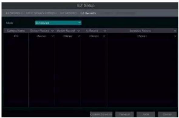
⑧ EZ Record Sengs. Two record modes are available: auto and scheduled.
Auto: Select one auto mode in the interface as shown below and then click "Next" to save your sengs. Click "Advanced" to self-dene record mode. See 7.1.1 Mode Conguraon for details.
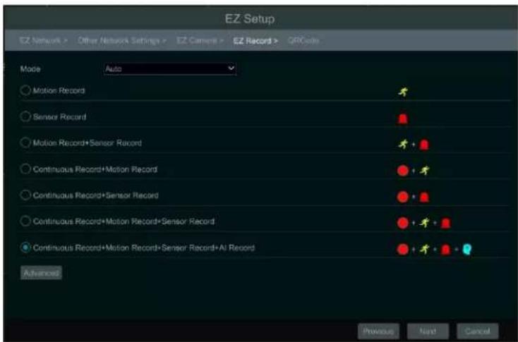
Scheduled: Set the "Sensor Record", "Moon Record" and "Schedule Record" of each camera. Click "OK" to save. See 7.1.1 Mode Conguraon for
details.
⑨ QR Code. Enable the NAT funcon in the interface or set it in the network conguraon aer exing the wizard (please refer to 14.1.8 NAT Conguraon for details). You can scan the QR Code through the Speco Blue App available for iOS and Android to view your cameras easily and securely. Please refer to 15.1 Mobile Client Surveillance for details. Click "OK" to save your sengs.
⑩ Cloud Upgrade. Enable "Cloud Upgrade" and then click "OK" to save. If this funcon is enabled, you will get the latest version from the cloud server. Please refer to Cloud Upgrade secon for details. Only user levels with "Network" access will be able to enable/disable cloud upgrades.
3.2 Main Interface
3.2.1 Main Interface Introducon

The buons in area ① are described in the table below.
| Buon | Meaning | |
| Start buon. Click to open area 3. | ||
| Full screen buon. Click to show full screen and hide area 2; click again to exit the full screen. | ||
| Screen mode buon. | ||
| Dwell buon (see 5.2.2 Quick Sequence View and 5.2.4 Scheme View InSequence for details). | ||
| Click to enable OSD; click again to disable OSD. | ||
 | Clickto set the default playback me before starng instant playback (8.1__Instant Playback) or going to the playback interface for playback operaons (8.2 Playback Interface Introducon):clickto to the playback interface. For instance, if you choose "5 minutes ago" as the default playback me, you can playback the recording from the past ve minutes. | |
| [H0X8] | Manual record buon. Click to enable/disable record. | |
 | Manual alarm buon. Click to trigger or clear the alarm-out manually in the popup window. | |
| [W077] | Record status buon. Click to view the record status. | |
 | Alarm status buon. Click to view the alarm status. | |
| [00WK] | Voice broadcast buon. Click to select the channel to broadcast. | |
 | Disk status buon. Click to view the disk status and RAID status. | |
 | Network status buon. Click to view the network status. | |
| [4ABB] | Informaon buon. Click to view system informaon. | |
| Click to enable the cloud upgrade feature. | ||
Introducon of area ②:
Click "Camera" to view all the added cameras in the camera list. Select one camera window on the le side of the interface and then double click one camera in the list to preview the camera image in the selected window.
Click "Single Channel Sequences" to view all the added groups in the group list; click one group in the list to view all the added cameras in the group (refer to 4.2 Add/Edit Camera Group for detail conguraon of the camera group). Select one camera window on the le side of the interface and then double click one group in the group list to preview the cameras' images one by one in the selected window.
Click "Customize Layout" to view all the display modes in the display mode list (refer to 5.2.1 Display Mode for detail conguraon of the display mode). Double click one display mode in the list to switch to the display mode for previewing.
Click "Target Detecon" to go to target detecon interface. This tab will show the captured human, vehicles, license plates and face images. (This funcon is only available for some models using the appropriate cameras).
Introducon of area ③:
| Icon / Buon | Meaning | |
  | It shows the current acve user. Click the QR code icon to view the QR code and security code. Users can quickly add the NVR to the server list of the mobile APP by scanning this QR code. | |
 | Click to go to the intelligent analycs interface. | |
 | Click to go to record search and export interface, see 8.4 Record Search, Playback & Export for details. | |
 | Click to go to playback interface (click on the tool bar at the top of the live view interface to set the default playback me), see 8.2 Playback Interface Introducon for details. | |
 | Click to open the setup panel, see 3.2.2 Setup Panel for details. | |
 | Click to log out the system. | |
| [H3BG] | Click and then select "Logout", "Reboot" or "Shutdown" in the popup window. | |
 | Click to go to the EZ setup menu. | |
3.2.2 Setup Panel
Click Start→Sengs to open the setup panel as shown below.

The setup panel includes seven modules. Each module provides some funcon entries with links for convenient operaon.
Take Camera module as an example. The Camera module provides convenient links such as "Add Camera", "Edit Camera", "Image Sengs", "Motion", "Intelligence Analysis" and "PTZ". Click Camera to go to the camera management interface as shown below.
There are some funcon items on the le side of the camera management interface. Click each item to go to corresponding interface or window. For instance, click "Add Camera" to open the window below.

Click the main menus on the top of the camera management interface to go to corresponding interfaces. Refer to the picture below. For instance, you can go to the system setup interface by clicking "System" tag.

3.2.3 Main Funcons
Camera
This module covers the funcons such as Camera Management (see Chapter 4 Camera Management for details), Image Sengs (see 5.3 Image Conguraon for details), Moon (see 11.2.1 Moon Conguraon for details), and PTZ (see Chapter 6 PTZ for details) and so on.
Record
This module covers funcons such as Encode Parameters and Record Schedule. Please see Chapter 7 Record & Disk Management for details.
AI/Event
This module covers funcons such as Sensor and Moon Alarm Handling and Alarm Out Sengs. Please see Chapter 9 AI Event Management and Chapter 11 General Event Management for details.
Disk
This module covers funcons such as Disk Management, Storage Mode and Disk Informaon. Please see Chapter 7 Record & Disk Management for details.
Network
This module covers funcons such as TCP/IP, DDNS, Port, E-mail and Network Status. Please see 14.1 Network Conguraon for details.
Account and Authority
This module covers funcons such as Account Management (see 13.1 Account Management for details) and Permission Management (see 13.3 Permission Management for details).
System
This module covers funcons such as Basic Conguraon (see 14.2 Basic Conguraon for details), Device Informaon (see 14.8 View System Informaon for details), Log Informaon (see 14.7 View Log for details) and Conguraon File Import & Export (see 14.5 Backup and Restore for details).
4 Camera Management
4.1 Add/Edit Camera
4.1.1 Add Camera
The network parameters of the NVR should be set before adding an IP camera (see 14.1.1 TCP/IP Conguraon for details).
Refer to the pictures below. Click Add Camera in the setup panel or + in the top right corner of the preview window to open the "Add Camera" window below. You can quickly add from a list, or else add the IP camera manually.


> Quickly Add
Check the cameras and then click "Add" to add cameras. Click 📋 to edit the camera's IP address, username, password and so on. Click "Default Password" to set the default username and password of each camera.

Add Manually
Enter the IP address or domain name (click √ in the IP address column to open the domain name input window, enter the domain name of the IPC in the window and then click "OK" buon), port, username and password of the camera and then select the protocol. Click "Test" to test the accuracy of the input informaon and then click the "Add" buon (you can input one camera's informaon as shown above such as IP address,
username and password before clicking "Add" buon). Click password of each camera.
to delete the camera. Click "Default Password" to set the default username and
Note: Some models may not support this funcon.
Click Start→Sengs→System→Basic→General Sengs to check "Enable Add IPC by Zero Operaon". If the NVR has unoccupied channels, it can add IPC without any operaon by restarng.
Add Recorder

- Quickly Add: Select the searched NVR/DVR and the click "Add" to add an NVR on the same local network.
- Manually Add: Click "Manual Add" and then enter the IP address or domain name, port, username and password of the NVR/DVR. Check the added remote channel number and click "Test" to test the accuracy of the input informaon. Then click the "OK" buon to return to the previous interface.
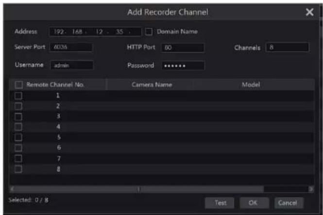
Note: IPC from other NVR/DVR on the same local network can only be added if your NVR has open channels and the added IPCs support previewing and recording.
4.1.2 Edit Camera
Click "Edit Camera" in the setup panel to go to the interface as shown below. Click 🎨 to view the live image of the camera in the popup window. Click 🔒 to edit the camera (see Add camera in 3.1 EZ Setup for details). Click 🔒 to delete the camera. Click √ in the "Operaon" header line and then click "Modify IPC Password" to pop up a window (check the IPCs in the window, set the new password and then click "OK" buon; only the online IPCs' passwords can be modied, and a batch of IPCs' passwords can be modied at the same me). Click ↑ upgrade an online IPC (or click √ in the "Upgrade" header line and then click "IPC Batch Upgrade" to upgrade a batch of IPCs), select the device which stores the upgrade le in the "Device Name" item of the popup window and the upgrade le in the list (you should select the upgrade IPC model in the window if a batch of IPCs' passwords need to be modied) and then click "Upgrade" buon to start (the IPC will restart automacally after the upgrade is completed successfully).
IP PoE cameras directly connected to the PoE ports of the NVR will be displayed automatically in the camera list. Refer to the picture above. The PoE camera directly connected to the PoE port has a prex shown before its camera name. The prex consists of PoE plus PoE port number. A PoE camera directly connected to the PoE port cannot be deleted from the camera list manually.
● An IP camera directly connected to the PoE port of the NVR through private protocol will be shown automatically in the camera list.
- One of two conditions must be met for an IP camera directly connected to the PoE port of the NVR through ONVIF protocol to be shown automatically in the camera list:
√ The IP camera directly connected to the PoE port is in the same network segment with the internal Ethernet port.
√ The DHCP (obtain an IP address automacally) of the IP camera directly connected to the PoE port is enabled.
If the IP camera directly connected to the PoE port cannot be displayed automatically in the camera list, please refer to Q6 in Appendix A FAQ for details.
4.2 Add/Edit Camera Group
4.2.1 Add Camera Group
Click "Edit Camera Group" in the above interface to go to the interface as shown below.

Click + to open the window below. Set the group name and dwell me (the dwell me of the camera group sequence view) in the window. Check the cameras and then click "Add" to add group. Click √ to view the cameras in the group aer adding group.

4.2.2 Edit Camera Group

Click to modify the group informaon such as group name and dwell me. Click delete the group.
4.2.3 IP Planning
Some models may not support this funcon.
Click "IP Planning" to go to the interface as shown below. This funcon supports searching other NVRs/DVRs that are in the same local network as the local NVR. The user may add camera channels of other NVRs/DVRs into the unoccupied channels of the local NVR.

Click to edit the IP address, username or password and other informaon of the NVRs.
Click ▼ behind "Add" buon to add the camera channels selected and the user may edit the IP address, username or password by clicking behind the "Edit" buon.
5 Live View Introducon
5.1 Live View Interface Introducon
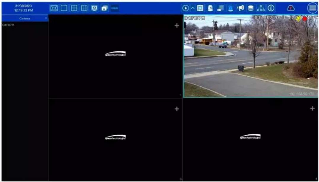
You should add cameras when rst logging into the system (see 4.1.1 Add Camera for details). Refer to the interface shown below and drag one camera in the preview window to another window to exchange windows.
The record symbols with dierent colors in the live view window refer to dierent record types: green stands for manual record, red stands for sensor-based record, yellow stands for moon based record, blue stands for scheduled record and cyan stands for intelligent record.

Click the preview window to show the tool bar as shown in area ①; right click the preview window to show the menu list. The tool bar and menu list are introduced in the table below.
| Buon | Menu List | Meaning |
| -- | Move tool. Click to move the tool bar anywhere. | |
| Manual Record On | Click to start recording. | |
| Instant Playback | Click ▶ to playback the recording; click “Instant Playback” to select or self-dene the instant playback me. See 8.1 InstantPlayback for details. | |
| Enable Audio | Click to enable audio. You can listen to the camera audio by enabling audio. | |
| Snap | Click to open the snapshot window. Click “Save” in the window to save the image. Click “Export” to export the image. | |
| PTZ Control | Click to go to PTZ control interface. See Chapter 6 PTZ for details. | |
| Zoom In | Click to go to single channel amplicaon interface. | |
| -- | Click to go to image adjustment interface. Refer to 5.3.4 Image Adjustment for details. | |
| Start Talk | Click to start two-way talk. Only some cameras support. | |
| Target detecon | Click to go to single channel target detecon interface; the target includes faces, human bodies and vehicles. | |
| -- | Camera Info | Click to view the camera information. |
The single channel zoom amplicaon interface is shown below. Press and drag the blue box to select the area to zoom in on. Click zoom the image. Click the camera selecon box to select other cameras for amplicaon. Click "Back" to return to the live view interface.

natural_image
Highway traffic scene with multiple cars on elevated tracks and a close-up of a multi-lane highway with visible tracks and lane markings (no text or symbols)5.2 View Mode
5.2.1 Display Mode
Set dierent screen modes and camera display sequences as needed and then save the display modes classed by surveillance areas, priories and so on. Refer to the picture below. Double click one display mode in the display mode list to view the live images in this mode.
▶ Add Display Mode
Method One:
① Click "Customize Display Modes" in the above interface
② Click ☐ to add a display mode name and then set the screen mode.
③ Add the cameras and adjust the cameras' display sequence as required.
④ Click under the display mode list.
Method Two:
① Click Start→Sengs→System→Basic→Output Sengs to go to the interface and then set the screen mode.
② Double click the camera or camera group in the list to add them to the selected window.
③ Click ★ to save the current display mode (refer to 5.2.4 Scheme View in Sequence for detail conguraons). The display mode will be saved and displayed in the display mode list in the live preview interface.
Edit Display Mode
Click "Customize Display Modes" tab in the live preview interface and then select one display mode in the list. Click 📁 to edit the display mode
name; click delete the display mode.
5.2.2 Quick Sequence View
You can start quick sequence view if the scheme has not been created. If the scheme has been created, please refer to 5.2.4 Scheme View in Sequence for details.

Go to the live view interface and then click 📋 to open a small window. Set the dwell me in the window and then click 📋 to view the live group by group according to the camera number of the current screen mode. Double click the sequence view interface to pause the view; double click again to restore the view. Click 📋 stop the view.
5.2.3 Camera Group View In Sequence
You can start camera group view in sequence if a camera group has been created (see 4.2.1 Add Camera Group for details). ① Go to the live view interface and then select a camera window.

② Double click one camera group on the right side of the interface. The cameras in the group will start camera group view one by one in the selected camera window.
You can also drag the group directly to any preview window. Right click on the group view window and then click "Close Dwell" buon to stop the view.
You can also add camera group in the live view interface. Select "Single Channel Sequences" and then click to modify the group name and sequence interval. Click to delete the group.
to add camera group. Click
5.2.4 Scheme View In Sequence
Click Start→Sengs→System→Basic→Output Seings to go to the interface as shown below.
Area ① displays all the dwell schemes; area ② shows the detailed informaon of the scheme; area ③ displays all the cameras and groups; area ④ is the tool bar (☐: clear buon; ☆: favorite buon, click to open a window, enter the display mode name in the window and then click "OK" to save the current display mode; other buons are screen mode buons).

Add Scheme
Click + in area ① to create a new scheme. Click ✗ on the top right corner of the scheme to delete it.
Congure Scheme
a) Select a scheme in area ① and then click the screen mode buon on the tool bar to set the screen mode of the scheme.
b) Select a camera window in area ② and then double click the camera or group in area ③. The camera or group will be added into the selected window. You cannot repeat a camera in the same scheme. You can click the right-click menu "Clear" in area ② to remove a single camera or click to remove all the cameras.
c) Click "Apply" to save your sengs.
Start Sequence View
Go to the live view interface and then click 📋 to open a window. Set the dwell me in the window and then click 📋 to start scheme view in sequence. Double click the sequence view interface to pause the view; double click again to restore the view. Click 📋 to stop the view.
5.3 Image Conguraon
5.3.1 OSD Sengs
Click Start→Sengs→Camera→Image→OSD Sengs to go to the interface as shown below. Select the camera, enter the camera name (or double click the camera name in the camera list to change the camera name), enable or disable the name and me OSDs (if enabled, drag the red name and me OSDs directly in the image view area to change the OSDs' display posion) and select the date and me formats. Click "Apply" to save your sengs.

5.3.2 Image Sengs
Click Start→Sengs→Camera→Image→Image Sengs to go to the interface below. Select the camera and then set the brightness, contrast, saturaon and hue of the camera. Click "Advanced" buon or the camera list on the right side of the interface to open "Image Adjust" interface and then set the relevant items. Please refer to 5.3.4 Image Adjustment for detailed introducons of these items. You can click "Default" to restore the image sengs to the default factory seings.

5.3.3 Mask Sengs
Some areas of the image can be masked for privacy. Up to four mask areas can be set for each camera. Click Start→Sengs→Camera→Image→Mask Sengs to go to the interface as shown below. Select the camera and enable the mask. Click "Draw" buon and then drag the mouse on the image area to set the mask area; click "Delete" buon to delete the mask areas; click "Apply" to save your sengs.

5.3.4 Image Adjustment
Go to the live view interface and then click buon on the tool bar under the camera window to go to the image adjustment interface.
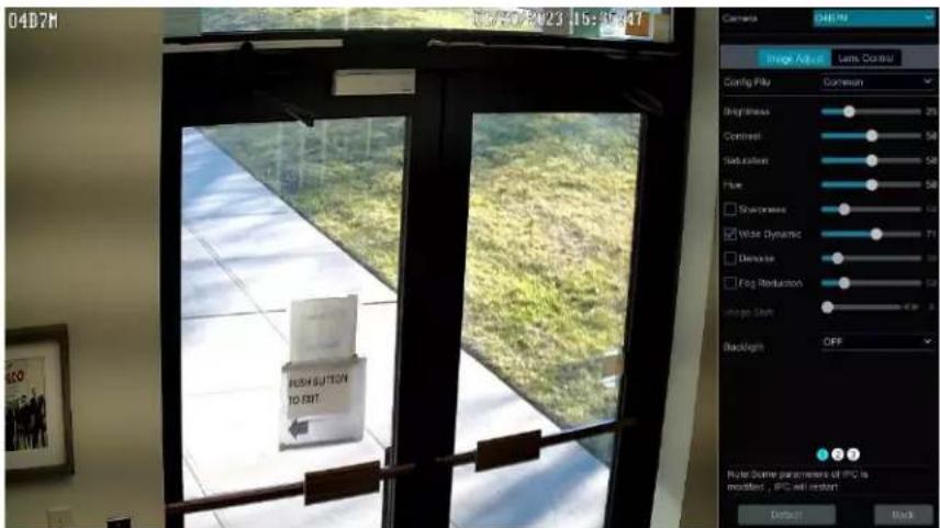
Image Adjustment
Select the camera and then click "Image Adjustment" to go to image adjustment tab. Refer to the picture above. Drag the slider to set the camera's brightness, contrast, saturaon and hue value. Check sharpness, wide dynamic and denoise and then drag the slider to set the value. Click "Default" buon to set these parameters to default values.
The introducons of these parameters are as follows:
| Parameter | Meaning |
| Brightness | The brightness level of the camera's image. |
| Contrast | The color dience between the brightest and darkest parts. |
| Saturaon | The degree of color purity. The image appears brighter the purer the color is. |
| Hue | Relates to the total color degree of the image. |
| Sharpen | Relates to the resoluon level of the image plane and the sharpness level of the image edge. |
| Wide Dynamic | The wide dynamic range (WDR) funcon helps the camera provide clear images even under back light circumstances. When there are both very bright and very dark areas simultaneously in the eld of view, WDR balances the brightness level of the whole image and provide clear images with details. |
| Denoise | Decrease the noise and make the image more thorough. Increasing the value will make the noise reducon eect beer but it will reduce the image resolution. |
| White Balance | Automacally adjust the temperature color according to the environment. |
| BLC | HLC: lowers the brightness of the enre image by suppressing the brightness of the image's bright area and reducing the size of the halo area.BLC: If enabled, the auto exposure will acvate according to the scene so that the object of the image in the darkest area will be seen clearly. |
| Corridor Paern | 0°, 90°, 180° or 270° can be selected. (Only some cameras support this paern) |
| Image Mirror | Turn the current video image horizontally. |
| Image Flip | Turn the current video image vercally. |
| High FPS Mode | High frame rate mode, if is it enabled, the frame rate of the camera's mainstream can be set to 1080P/720P @60fps/50fps. (Only some cameras support this mode) |
| Gain Mode | Choose "Auto" or "Manual". If "Auto" is selected, the gain value will be automacally adjusted according to the actual situaon. If "Manual" is selected, the gain value should be set manually. The higher the value is, the brighter the image is. |
| Infrared Mode | Choose "Auto", "On" or "O" as needed. |
| Shuer Mode | Choose "Auto" or "Manual". If manual is chosen, the digital shuer speed can be adjusted. |
| Day & Night Mode | Choose "Auto", "Day", "Night" or "Timing" as needed. |
| White Light Mode | "Auto", "Manual" or "O" can be selected. (Only some cameras support this mode). |
Note: The above-menoned descripons of the image parameters are for reference only. The cameras made by dierent manufacturers may have dierent parameter sengs.
Lens Control
Select the camera and then click "Lens Control" to go to lens control tab. Click - or + to adjust the zoom and focus parameters of the camera's lens. Click "Save" to save your sengs.
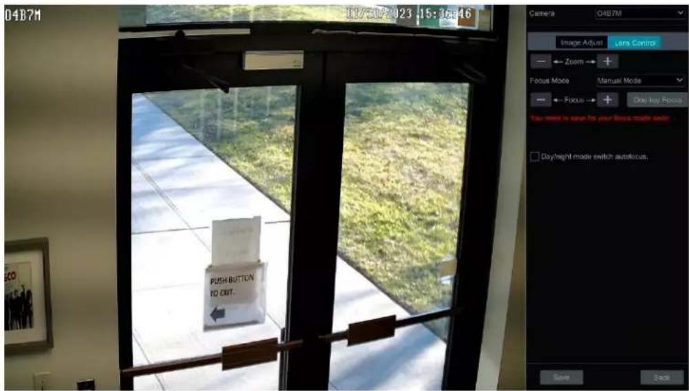
The introducons of these parameters and buons are as follows.
| Buon/Parameter | Meaning |
 | Click [AWXB], z1 [BYXW]   ige. ige. |
| Focus Mode | If manual mode is selected, focus buon & “One Key Focus” & “Day/night mode switch autofocus” will be available; if auto mode is selected, the me interval setup will be available. |
 | Click  / /     se the focal length. se the focal length. |
 | Click it to focus instantly. |
| Day/night mode switch autofocus | If checked, the lens will focus automacally when the camera is switching day/night mode. |
| Time Interval | It is the me interval when camera lens is auto focusing. The interval can be set in the drop-down list. |
Note: Funcon is only available for motorized zoom cameras.
5.3.5 Fisheye Sengs
Some models may not support this funcon.
Click Start→Sengs→Camera→Image→Fisheye Sengs to go to the interface as shown below. Select the camera and the mode of sheye and installaon.

6 PTZ
6.1 PTZ Control Interface Introducon
You can control an IP dome or PTZ connected to the IP camera for PTZ control.
Click 📄 on the tool bar at the boom of the live preview window to go to the PTZ control interface as shown below.

The direcon, zoom, focus, iris and speed can be controlled in the small PTZ control window.
Right click the PTZ/speed dome camera window and select "PTZ Control" to go to the PTZ control panel as shown below.

Introducons of the buons on the boom right of the interface:
| Buon | Meaning |
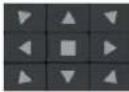 | Click / / / / / / / / / / to rotate the dome. Click to stop rotang the dome. |
 | Click / - to zoom in / out the camera image. |
 | Click / to increase / decrease the focal length. |
 | Click / - to increase / decrease the iris of the dome. |
 | Drag the slider to adjust the rotang speed of the dome. |
 | Click to / stop recording. |
 | Click / to hide / show the analog joysck. |
| ### | Click it to return to the live view interface. |
Analog Joysck Control
The analog joysck on the le side of the interface provides quick PTZ control. The dome or PTZ will rotate when you drag the analog joysck. The farther you drag the analog joysck from the middle of the image, the faster the dome or PTZ rotates. The dome or PTZ will stop rotang when you
stop dragging the analog joysck.
3D Control
Click the camera image on any area and the image will be centered on the clicked point.
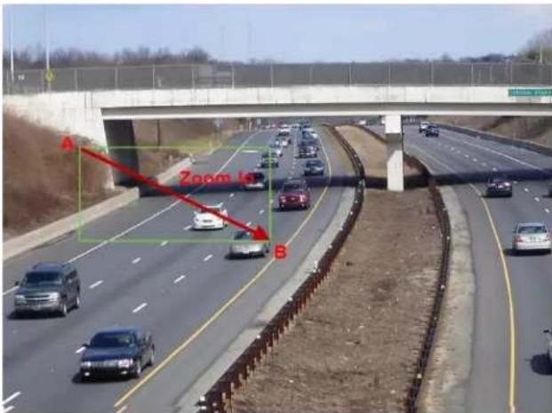
Refer to the picture as shown below. Drag the mouse from A to B to get a green rectangle and the rectangle area will be zoomed in.
Refer to the picture as shown below. Drag the mouse from C to D to get a green rectangle and the rectangle area will be zoomed out.

Advanced 3D Control
Double click the le buon of the mouse on any area of the camera image and then the image size will be doubled and centered on the clicked point. Press and hold the le buon of the mouse on any area of the camera image to zoom in on the image; press and hold the right buon to zoom out of the image.
Move the cursor of the mouse to the camera image and then slide the scroll wheel of the mouse forward to zoom in on the image, slide the scroll wheel of the mouse backward to zoom out of the image.
Preset Sengs
Click "Preset" to go to preset operaon tab and then click the "Add" buon to open the window below. Select the preset and then enter the preset name in the window; nally click the "OK" buon to save your sengs. You can add up to 255 presets for each dome.

Adjust the dome's direcon and then click "Save Posion" to save the current preset posion (you can also click another preset in the preset list and
then save the preset posion aer adjuusng the dome's direcon); click selected preset.
i: a preset list to call the preset; click "Delete" buon to delete the
You can also go to preset sengs interface for preset setup, see 6.2 Preset Seng for details.
Cruise Sengs
Click "Cruise" to go to cruise operaon tab and then click "Add" buon to open the window below. You can add up to 8 cruises for each dome.

① Enter the cruise name in the "Add Cruise" window and then click "Add preset" to open the "Add Preset" window (Before adding preset to the cruise, please add preset of the dome rst).
② In the "Add Preset" window, select the preset name, preset me and preset speed and then click "OK."
③ In the "Add Cruise" window, you can click to reselect the preset, then change the preset me and speed. Click to delete the preset.
Click "Add" buon to save the cruise.
Click ▶ to start the cruise and click □ to stop the cruise in the cruise list of the cruise operaon tab; click the "Delete" buon to delete the selected cruise.
You can also go to cruise sengs interface for cruise setup, see 6.3 Cruise Sengs for details.
Cruise Group Sengs
On the right panel, click ▶ to go to the cruise group sengs tab. Click "Add" to add a cruise group as shown below.
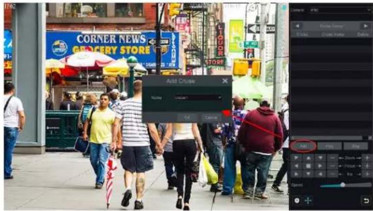
In the "Add Cruise" window, select the cruise group name. Aer that, click "Play" to play the cruise groups in sequence.
Trace Sengs
On the right panel, click ▶ to go to the trace sengs tab. Click "Add" to add the trace name. Then click "OK" to save this name. Please refer to the following picture:
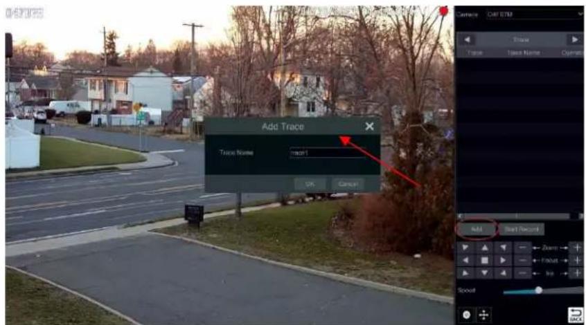
Aer that, click "Start Record" to record the trace. Then click "Stop Record" to nish recording. Click delete the trace.
play the recorded trace. Click

6.2 Preset Sengs
Click Start→Sengs→Camera→PTZ→Preset to go to the interface as shown below.
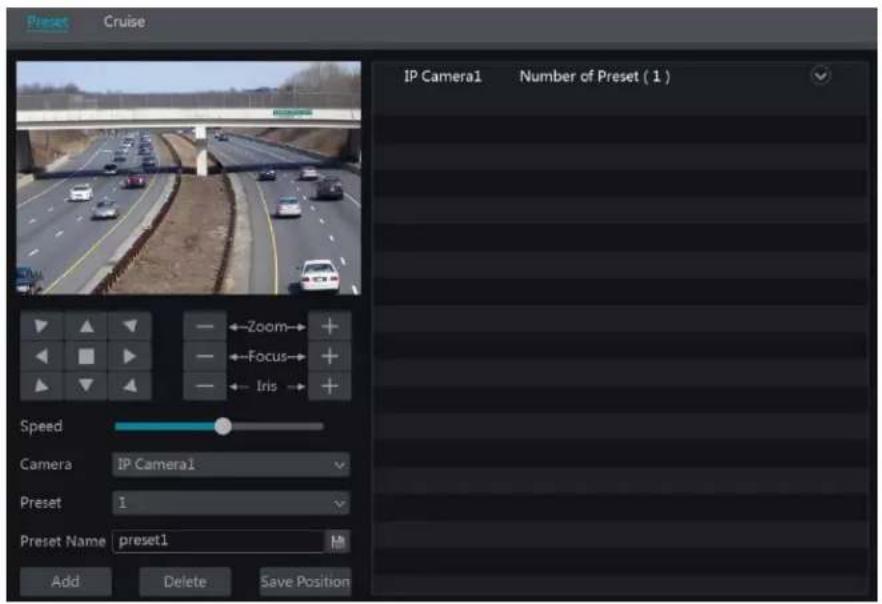
Add preset
Select camera and then click "Add" buon to add a preset; or click in the camera list on the right side of the interface to display the preset information of the dome and then click + to add a preset. The operations of the "Add Preset" window are similar to that of the PTZ control interface; please see 6.1 PTZ Control Interface Introducon for details.
Edit preset
Select camera and preset. You can enter the new name of the preset and then click to save the new preset name. Adjust the rotang speed, posion, zoom, focus and iris of the preset and then click "Save Posion" to save the preset.
Delete Preset
Select camera and preset and then click "Delete" to delete the preset.
6.3 Cruise Sengs
Click Start→Sengs→Camera→PTZ→Cruise to go to the interface as shown below.

Add Cruise
Click in the camera list on the right side of the interface to display the cruise informaon of the dome and then click + to add cruise. The operaons of the "Add Cruise" window are similar to that of the PTZ control interface; please see 6.1 PTZ Control Interface Introducon for
details.
Edit Cruise
Select the camera and cruise in the "Cruise" interface. Enter the new cruise name and then click 📄 to save the cruise name. Click "Add Preset" to add a preset to the cruise. Click 🔒 to edit the preset. Click 🔒 to delete the preset from the cruise. Click one preset in the preset list and then click 🔒 to move down the preset and click 🔒 to move up the list. Click 🔒 to start the cruise and click 🔒 to stop it.
Delete Cruise
Click ☑ on the camera list on the right side of the interface to display the cruise informaon of the dome and then click ☒ on the top right corner of the cruise to delete the cruise.
6.4 Cruise Group Sengs
Click Start→Sengs→Camera→PTZ→Cruise Group to go to the interface shown below.

Add Cruise Group
Click "Add Cruise" to add the cruise, or click √ to extend the cruise list and then click + to add the cruise. Aer that, click "Play" on the le panel as shown below to play the cruise lines in sequence.
Delete Cruise
In the cruise list, click delete the cruise.
6.5 Trace Sengs
Click Start→Sengs→Camera→PTZ→Trace to go to the interface as shown below.
Trace Record
Select the PTZ camera and then click "Add" or extend the IPC informaon by clicking √ and then click + to add a trace name. Aer that, click "Start Record" and move the speed dome to change its posion and set its trace. Then click "Stop Record" to complete the trace record.

Play or Stop Trace
Select the trace and click ▶ to play the trace; click ■ to stop the trace.
Modify the Trace Name
On the le panel, enter new trace name and click to modify and save the trace name.
Delete the Trace
Click 📄 to delete the trace. Or put the cursor on the trace name (right panel) and then ✗ will appear on the right corner of the trace name; click it to delete this trace.
6.6 Task Sengs
Click Start→Sengs→Camera→PTZ→Task to go to the interface as shown below.
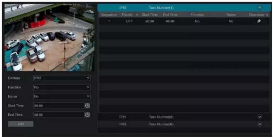
① Select a PTZ camera.
② Select funcon, such as preset, cruise, trace, random scanning, etc.
③ Select a name, such as preset name, cruise name, etc.
④ Select the start and end me.
⑤ Click "Add" to add the task.
⑥ Click ▼ to extend the tasks of the PTZ camera. Click ▼ beside "Enable" to enable the task. Aer the task is enabled, the PTZ camera will start the speci task at the specied me.
6.7 Smart Tracking
This funcon is only available with Speco Technologies' AI PTZ cameras. Please add an AI PTZ camera to the NVR for this funcon to take eect. Smart Tracking: When people or vehicles cross the alarm line or intrude the predened area, the PTZ camera can automatically track them and the
target image will be automatically zoomed in and centered on the screen until the target disappears from the screen. Aer that, the PTZ camera will return to the tracking start position.
To set smart tracking:
- Click Sengs→Camera→Smart Tracking to go to the smart tracking interface.
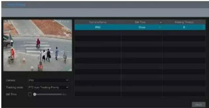
- Select the tracking mode and set the "sll me" as desired.
Tracking Mode: Choose between PTZ Auto Tracking Priority or Manual PTZ Control Priority.
PTZ Tracking Priority: if this mode is selected, aer enabling "Trigger track" in one of the following events you cannot control the PTZ by clicking the buons on the PTZ control panel in the live view interface.
Manual PTZ Control Priority: if this mode is selected, aer enabling "Trigger track" in one of the following events, you can control PTZ by clicking the buons on the PTZ control panel in the live view interface during the process of smart tracking. Aer you stop controlling for 5 seconds, the PTZ camera will return to the pre-dened detecon area and start tracking again when detectcng a target.
Sll me: If it is enabled and the me is set, if the target stops or hides behind an obstacle, or the target tracking is complete and there is no target appearing in the detecon area during the set me, the PTZ camera will return to the tracking start posion aer the set me expires. During this me, if there are targets moving the PTZ will connue tracking. If it is not enabled, when the target stops or there is no target appearing in the detecon area for 5 seconds, the PTZ camera will return to the start tracking posion.
For example: At the stoplight, if a car is waiing for the red light for 30 seconds, and the "sll me" is set as 20 seconds, the tracking will stop following; however, if the "sll me" is set as 40 seconds, when the red light changes to green and the car starts to move, the PTZ will connue tracking this car.
- Click Sengs→AI/Event→AI Event. Select the AI PTZ camera and the event as needed (Line Crossing/Intrusion). For example: intrusion.

- Enable the event, set the rule and then click "Locked". This buon will be changed to "Unlock". Now the PTZ control panel in the above interface will be acvated. Set the detecon area by clicking the direconal buons in the above interface. Aer that, click "Unlock" to lock the detecon area.
Note: The PTZ must be locked, or the smart tracking cannot take eect.
-
Click "Draw area" and then draw the intrusion region on the screen. Aer that, check "Trigger Track" and click "Apply" to save your sengs.
-
Set the detecon target.
-
Click "Apply" to save setngs.
7 Record & Disk Management
7.1 Record Conguraon
7.1.1 Mode Conguraon
Please format the HDDs before recording (refer to 7.4.1 Disk Management for details). Click Start→Sengs→Record→Mode Sengs to go to the mode sengs interface. You can set the record me under the "Manual Record Seings" and then click "Apply" to save your sengs. There are two record modes: auto mode and scheduled mode.

Auto Mode
Moon Record: Moon alarm record will be enabled when moon alarm is triggered.
Sensor Record: Sensor alarm record will be enabled when sensor alarm is triggered.
Moon Record+Sensor Record: Moon/sensor alarm record will be enabled when moon/sensor alarm is triggered.
Connuous Record+Moon Record: Normal record is enabled all the me; moon alarm record will be started when moon alarm is triggered.
Connuous Record+Sensor Record: Normal record is enabled all the me; sensor alarm record will be started when sensor alarm is triggered.
Connuous Record+Moon Record+Sensor Record: Normal record is enabled all the me; moon/sensor alarm record will be enabled when moon/sensor alarm is triggered.
Connuous Record+Moon Record+Sensor Record+ AI Record: Normal record is enabled all the me; moon/sensor/analycs alarm record will be enabled when moon/sensor/intelligence analycs alarm is triggered.
You can add more auto modes on intelligence record. Click "Advanced" buon to open the window below. Check the modes in the window and then click "Add" buon to show the modes in the record mode list (in the window, the checked modes can be shown in the record mode list while the unchecked modes cannot; you should check "AI Record").

Select one auto mode for the corresponding window to open. Set the encode, GOP, resoluon, FPS, bitrate type, quality, max bitrate and audio of each camera and then click "OK" to save your seings. Please adjust the parameters according to the actual condition.

Video Encode: the available opons will be H.265 and H.264 depending on what the camera supports.
Resoluon: the higher the resoluon is, the clearer the image is.
FPS: the higher the frame rate is, the more uency the video has, with the tradeo of using more storage.
Bitrate Type: CBR and VBR are oponal. CBR means that no maer how much change is seen in the video scene, the compression bitrate will be kept constant. VBR means that the compression bitrate will be adjusted according to scene changes. For example, for scenes that do not have much movement, the bitrate will be kept at a lower value. This will help to optimize the network bandwidth.
Quality: When VBR is selected, you need to choose image quality. The higher the image quality you choose, the more bitrate will be required.
Max Bitrate: 32Kbps \~10240Kbps are oponal.
GOP: Group of Pictures.
Scheduled Mode
If scheduled mode is selected, you need to set the recording schedules for each camera. See 7.1.2 Schedule Sengs for details.
7.1.2 Schedule Sengs
Add Schedule
Click Start→Sengs→Record→Mode Seng to go to the mode seng interface. Then select "Scheduled" mode and click "Schedule Management" to set the schedule as shown below. "24 x 7", "24 x 5" and "24 x 2" are the default schedules; you cannot edit or delete "24 x 7" while "24 x 5" and "24 x 2" can be edited and deleted. Click the schedule name to display the detailed schedule informaon on the le side of the interface. The seven rows stand for the seven days in a week and each row stands for 24 hours in a day. Blue stands for the selected me and gray stands for unselected me.

Click "Add" to add a new schedule. Refer to the picture below.

Set the schedule name and schedule me and then click "Add" to save the schedule. You can set day schedule or week schedule.
add buon;
MIL: delete buon.
Set Day Schedule
Click 📊 and then drag the cursor on the me scale to set record me; click area.
and then drag the cursor on the time scale to delete the selected
You can manually set the recording start me and end me. Click or then click "Manual" on each day to open the window below. Set the start and end me in the window and then click "OK" to save your sengs.

Click "All" to set all day recording; click "Reverse" to swap the selected and unselected me in a day; click "Clear All" to clear all the selected area in a day.
Click "Copy To" to copy the schedule of the day to other days. Refer to the picture below. Check the days in the window and then click "OK" to save your sengs.

Set Week Schedule
Click 📄 or 📋 and then click "Manual" beside 📋 to set the week schedule. Refer to the picture below. Set the start and end me, check the days in the window and then click "OK" to save your sengs.

Click "All" to set all week recording; click "Reverse" to swap the selected and unselected me in a week; click "Clear All" to clear all the selected area in a week.
7.1.3 Advanced Conguraon
Click Start→Sengs→Record→Advanced to go to the interface below. Enable or disable overwrite mode (overwrite mode: the earliest recording data will be replaced by the latest when the disks are full). Choose the record stream. Set the pre-alarm record me, post-alarm record me and expiraon me of each camera and then click "Apply" to save your sengs.

Pre-alarm Record Time: set the me to record before the actual recording begins.
Post-alarm Record Time: set the me to record aer the actual recording is nished.
Expiraon Time: set the expiraon me for recorded video. If the set date is overdue, the recorded data will be deleted automatically.
7.2 Encode Parameters Sengs
Click Start→Sengs→Record→Encode Parameters to go to the interface as shown below. Set the encode, resoluon, FPS, GOP, bitrate type, quality, max bitrate and audio of main stream for each camera in "Event Recording Sengs" and "Schedule Recording Sengs" interfaces. Click "Apply" to save your sengs. You can set the record stream of each camera one by one or batch set them for all cameras.

Click the "Record Substream" tab to set the record substream. Select "Auto" and the system will automatically set the record substream. Select "Manual" to set the encode, resoluon, frame rate and max birate of the record substream manually.

7.3 Record Mode
7.3.1 Manual Recording
Method One: Click on the tool bar at the top of the live view interface to enable recording of the camera.
Method Two: Go to the live view interface and then click the right-click menu "Manually Record On" in the camera window or click on the tool bar under the camera window to start recording.
Note: Click Start → Settings → Record → Mode Settings and then set the manual record time in the interface. Click "Apply" to save your settings.
7.3.2 Timing Recording
Timing Recording: the system will record automatically according to the schedule. Set the ming record schedule of each camera. See 7.1.2 Schedule Sengs for details.
7.3.3 Moon Based Recording
Moon Based Recording: the system will start moon-based recording when the moon object appears in the setup schedule. The setup steps are as follows:
① Set the moon-based recording schedule of each camera. See 7.1.2 Schedule Sengs for details.
② Enable the moon and set the moon area of each camera. See 11.2 Moon Alarm for details.
The camera will start moon-based recording once you nish the above steps.
7.3.4 Sensor Based Recording
① Set the sensor-based recording schedule of each camera. See 7.1.2 Schedule Sengs for details.
② Set the NO/NC type of the sensor, enable the sensor alarm and then check and congure the "Record". See 11.1 Sensor Alarm for details.
7.3.5 AI Event Recording
① Set the analytics recording schedule of each IP camera. See 7.1.2 Schedule Sengs for details.
② Enable the intelligent alarm detecon (object detecon, excepon, tripwire or intrusion) and draw alert surface or warning area of each IP camera. See 9 AI Event Management for details.
The camera will start analyc recording once you nish the above steps. This funcon is only available for some Speco Blue IPCs.
7.4 Disk
7.4.1 Disk Management
▶ Disk Management
Click Start→Sengs→Disk→Disk Management to go to the disk management interface. You can view the NVR's disk number and disk status and so on in the interface. Click "Format" buon to format the HDD.
![Disk Management Disk Free/Capacity[GB] Disk Serial No. Disk Model Status Type Overwrite mo... Operation Record Pi Disk2 438.69/465 W2A3F7XW ST500DM002-1BD142 RW(Not Encrypted) Ordinary Pi... ON Format 08/22/202 Unlock Data Encrypt](/content/2026/05/1083299/images/1027b765eb2ff2d739fcc62cebeaa79e0b8f5f86971951015a91f26e8268bbba.jpg)
Data Encrypon:
① Click "Data Encrypt".
② Enter the username and password used to log into the NVR. This username and password must have disk management permission.
③ Check the disk you want to encrypt and then enter the password.
Aer you encrypt the data of a disk, this disk cannot be read by other NVRs unless it is unlocked.
Data Decrypon:
① Click "Change Encrypon".
② Enter the username and password used to log in the NVR. This user must have disk management permission.
③ Check the disk you want to decrypt and then clear the password.
④ Click "Close Encrypon".
Unlock the disk: when one encrypted disk is transferred from another NVR to this NVR, it will be locked. You can select this locked disk and click "Unlock". Aer you enter the password of its data encrypon, its status will be "Read Only". Now you can read the data of this disk but nothing can be written to it.
Some models may not support RAID funcon. RAID sengs are as follows: Please skip the sengs of physical disk, array and disk mode if the NVR doesn't support this funcon. Check the spec sheet for your model to conrm if it supports RAID.
RAID
① Enable RAID
(Go to Start→Sengs→Disk→Disk Mode)

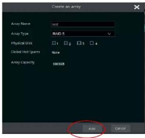
② Create an array. (Go to Start→Seings→Disk→Physical Disk)
a. Click "Physical Disk" tab and then click "Create an array".
b. Enter the username and password that has Disk Management authority. If you don't have one, you can use the username and password for system login (the default username: admin; the default password:123456).
c. Enter array name and select array type (like RAID5).

d. Select physical disk.
If you have 16 disks, please select 15 disks. The remaining one should be set to a hot spare.
If higher data security is needed, you can decrease physical disks and increase hot spare disks. Please set them as needed.
e. Select a hot spare. In the physical disk interface, select the disk that is not in the array and click as shown in the following pictures.
![Disk Capacity[GB] Array Type Status Disk Model Hot Spare 1 931 test Array disk Normal xxxxxx 2 931 test Array disk Normal xxxxxx 3 931 test Array disk Normal xxxxxx 4 931 Ordinary plane Normal XXXXX Authority authentication Enter Username Enter Password OK Cancel Question Disk set to global hot spare clears disk data, OK to continue? OK Cancel](/content/2026/05/1083299/images/5687851813bdb1c1d31f6723beabeb32abb0b6351bdbf9862aa385e621f45d36.jpg)
- RAID Rebuilding
If one of your disks is defective, the disk indicator on the front panel will turn red. A warning p will pop up if the relevant HDD exceed alarm is set. You need to rebuild your RAID conguraon aer you replace the broken disk with a new one.
![Disk Management Physical Disk Array Disk Mode No Name Capacity[GB] Physical Disk Hot Spare Position Status Type Rebuild 1 test 1862 23 A Downgrade RAID5](/content/2026/05/1083299/images/e0d6bb0131d57bff59fac64a0076f72e870d1aea58709c232978858416f953e1.jpg)
Click the above circled icon and then select the physical disk to rebuild.

7.4.2 Storage Mode Conguraon
Click Start→Sengs→Disk→Storage Mode to go to the interface as shown below.

By using a disk group, you can correspond a camera to disk (the recording data of the camera in the group will be stored into the disks in the same group). An NVR with e-SATA interface supports e-SATA recording.
The added disks and cameras will be added into group one automacally. The disks and cameras in the groups can be deleted except group one (select a disk group and then click ✗ on the top right corner of the added disk or camera to delete it from the group). The deleted disks and cameras will be moved into group one automacally.
Each group can add disks and cameras from other groups. Each disk and camera can only be added into one group. Select a disk group and then click in the disk or camera row to open a window. Check the disks or cameras in the window and then click "Add".
For models with 2 or 4 HDD slots, BK group can be added as shown below.

Click + to add the backup HDD. Aer account vericaon, select an HDD and then this HDD will be removed from the normal group to the backup group. Simultaneously, it will be formed. Please back up all data of this HDD in advance when you want to remove it to the backup group.
You can add cameras to this HDD. The added cameras can exist and be recorded both in one HDD of the normal group and the backup group. Note: Each HDD only can exist in one group.
7.4.3 View Disk and S.M.A.R.T. Informaon
Click Start→Sengs→Disk→View Disk Informaon to view the HDD informaon; click "S.M.A.R.T. Informaon" to view the working status of the HDD (refer to the picture below); click "Health Status Check" to check the disks' health status.

In addition, you can view the plug-in or pull-out details of the HDD from the logs to check whether someone has made changes to your HDD. Click Start→Sengs→System→View Log.
8 Playback & Backup
8.1 Instant Playback
Click ▶ on the tool bar at the boom of the preview camera window to play back the recording (click ▶ on the tool bar at the top of the live view interface to set the default playback me). Refer to the picture below. Drag the playback progress bar to change the playback me. You can also click the right-click menu "Instant Playback" in the camera window and then set the instant playback me to play back the record.

natural_image
Street scene with a road, residential buildings, and a speedometer overlay (no readable text or symbols)8.2 Playback Interface Introducon
Click 🎨 on the tool bar at the top of the live view interface or click Start→Playback to go to the playback interface as shown below (click 🎨 on the tool bar at the top of the live view interface to set the default playback me).
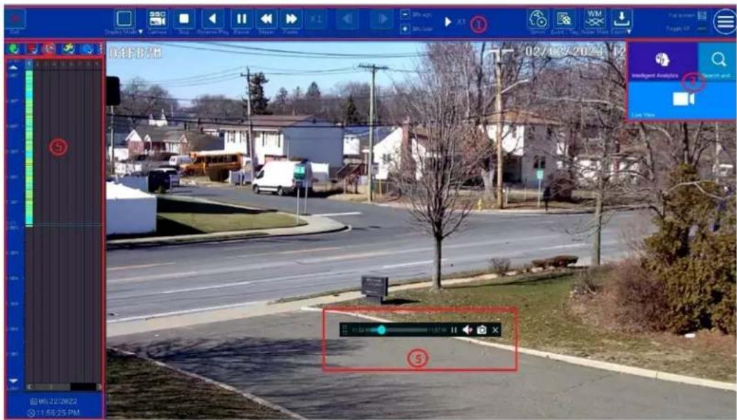
The panel on the le will show you the channel number and their recorded data coded by color. The bar that runs across them represents the playback me being viewed. You can move this bar around. To export, highlight a secon of the desired recording, click export and follow the prompts. You can export single or mulple channels at the same me.
The added cameras will playback their recordings in the playback interface automatically. You can also add the playback camera manually. Click in the playback window to open the "Add Camera" window. Check the cameras in the window and then click "Add" to add playback camera. The system supports a maximum of 16 synchronous playback cameras.
The buons on the tool bar (area ①) at the top of the playback interface are introduced in the table below.
| Buon | Meaning | |
| [0Y2D] | Start buon. Click to open area 2. | |
 | Full screen buon. Click to show full screen; click again to exit the full screen. | |
 | Screen mode buon. | |
 | OSD ON buon. Click to enable OSD; click it again to disable OSD. | |
 | Quick channel selecon buon | |
| [2W0D] | Stop buon. | |
| [0T46] | Rewind buon. Click to play video backwards. | |
| [YYTZ] | Play buon. Click to play video forwards. | |
 | Pause buon. | |
| [YOZ4] | Deceleraon buon. Click to decrease the playing speed. | |
| [1YXX] | Acceleraon buon. Click to increase the playing speed. | |
 | Previous frame buon. It works only when the forward playing is paused in single screen mode. | |
| [8A90] | Next frame buon. It works only when the forward playing is paused in single screen mode. | |
 | Click step backward 30s and click to forward 30s. | |
 | Click it to enter the smart playback interface | |
 | Event list/tag buon. Click to view the event recording of manual/schedule/sensor/ moon and the tag informaon. | |
| [KBKT] | Watermark buon. Click to enable a watermark; click again to disable watermark. | |
| [TDS8] | Backup buon. Drag the mouse on the me scale to select the me periods and cameras, and then click the buon to back up the record. Backup status buon. Click to view the backup status. | |
 | ||
 | Back buon. Click to return. | |
Introducon of area ②:
| Buon | Meaning | |
 | Click to go to record search and export interface; see 8.4 Record Search,Playback & Backup for details. | |
 | Click to go to the live view interface; see Chapter 5 Live View Introducon for details. | |
 | Click to go to the intelligent analycs interface. | |
Click on the playback window to show the tool bar as shown in area ③; right click on the window to show the menu list. The tool bar and menu list are introduced in the table below.
| Buon | Menu List | Meaning |
 | Move tool. Click to move the tool bar anywhere. | |
 | Click to enable audio. You can listen to the camera audio by enabling audio. | |
 | Click to take a snapshot. | |
 | Click to go to the zoom in interface. The zoom in interface is similar to that of the camera window in the live view interface.Clickto pause the record playing; clickto play the record. When the record is paused in forward playing mode, you can clickto view the previous frame and clickto view the next frame. | |
| [CYGB] | ||
 | ||
| Add Tag | Click to add tag. You can play back the recording by searching the added tag. Click and then enter the tag name in the popup window. Click “Add” to add tag. | |
| Switch Camera | Click to switch the playback camera. Click and then check the camera in the popup window. Click “OK” to change the camera. | |
| Close Camera | Click to close the playback camera. |
Introducon of area ④:
Click 📄 to set the date; click 🔒 to set the me and then the playback camera will play the record from the me you set. You can check the record type as required for record playback; rst you should click 📄 on the tool bar at the top of the interface to clear all the playback camera, then check the record type (☐: manual record; ☐: sensor based record; ☐: moon based record; ☐: schedule record; ☐: AI record; ☐: POS record, if you want view the detailed smart playback icons, click 📄 to switch). Finally, click + in the playback window to add camera for playback (the record me scale will show the record data of the checked record type only aer the above operaons).
Introducon of the record me scale (area ⑤):
Click to set the date; click to set the me and then the playback camera will play the record from the me you set.
A tool bar will appear aer moving the mouse to the record me scale. Click zoom the meline; click recover the meline to 24 hours' rao. Drag the timeline or slide the scroll wheel of the mouse on the me scale to show the hidden me on the top or boom of the meline. You can also click show the hidden me on the top of the meline or click show the hidden me on the boom of the meline. Drag the slider at the boom of the me scale to show the hidden playback cameras.
The record me scale shows dierent record types with dierent colors. The green block stands for manual record, red block stands for sensor based record, yellow block stands for moon based record, blue block stands for schedule record and cyan block stands for intelligent record. Click the record block to set the me and then the playback camera will play the record from the me you set. Drag the color block on the me scale to select the backup area and then right click the area or click 📁 to open an export informaon window. Click 📍 buon in the window to open the export window. Select the device, export path and format and then click "Export" buon to start the backup.
8.3 Smart Playback
In the playback interface, click 📋 to go to the smart playback interface.

The descripons of buons in the smart playback interface
| Buon | Descripon | |
| Full screen moon buon. | ||
| Draw grid. You can search the record of moon detecon in the pre-dened area. | ||
| Buon | Descripon | ||
| Draw line. You can search the record of crossing the line aer drawing the line. | |||
| Draw quadrilateral. You can search the record in this quadrilateral aer drawing it. | |||
 | Search by license plate number | ||
| Search by face (only supported by N8NRE/N16NRE/N32NRE) | |||
| Playback sengs buon | |||
| Return buon. Click to return to the previous interface. | |||
8.3.1 Smart Playback Sengs
Click 📋 to set "Moon/Face/Vehicle video playback speed", "Ordinary video playback speed".
You can disable "Common" to view moon/face vehicle video playback in the right corner of the smart playback interface.

8.3.2 Smart Playback Based on Moon Detection
● Smart Playback by Drawing Grid
Click 📄 and draw a rectangle in the desired area. The system will then automatically search the record les of this area. The cyan blocks indicate that there are intelligent recording les. Move the cursor to such block and click to play the record.
● Smart Playback by Drawing Line
Click and draw a line in the desired area. The system will then automatically search for the record les where this line was crossed. The cyan blocks indicate that there are intelligent recording les. Move the cursor to such a block and click to play the recording.

● Smart Playback by Drawing Quadrilateral
Click and draw a quadrangle in the desired area. The system will then automatically search the recording les of this area. The cyan blocks indicate that there are intelligent recording les. Move the cursor to such a block and click to play the recording.

natural_image
Street scene with residential buildings, parked cars, and a green bounding box highlighting a green area (no visible text or symbols)8.3.3 Smart Playback by Face Search
Before starng this funcon, the face recognition funcon must be enabled. Please see Face Recognition secon for details. If your device doesn't support such a funcon, please skip the following instrucons.
① In the smart playback interface, click 📄 to open the window below.
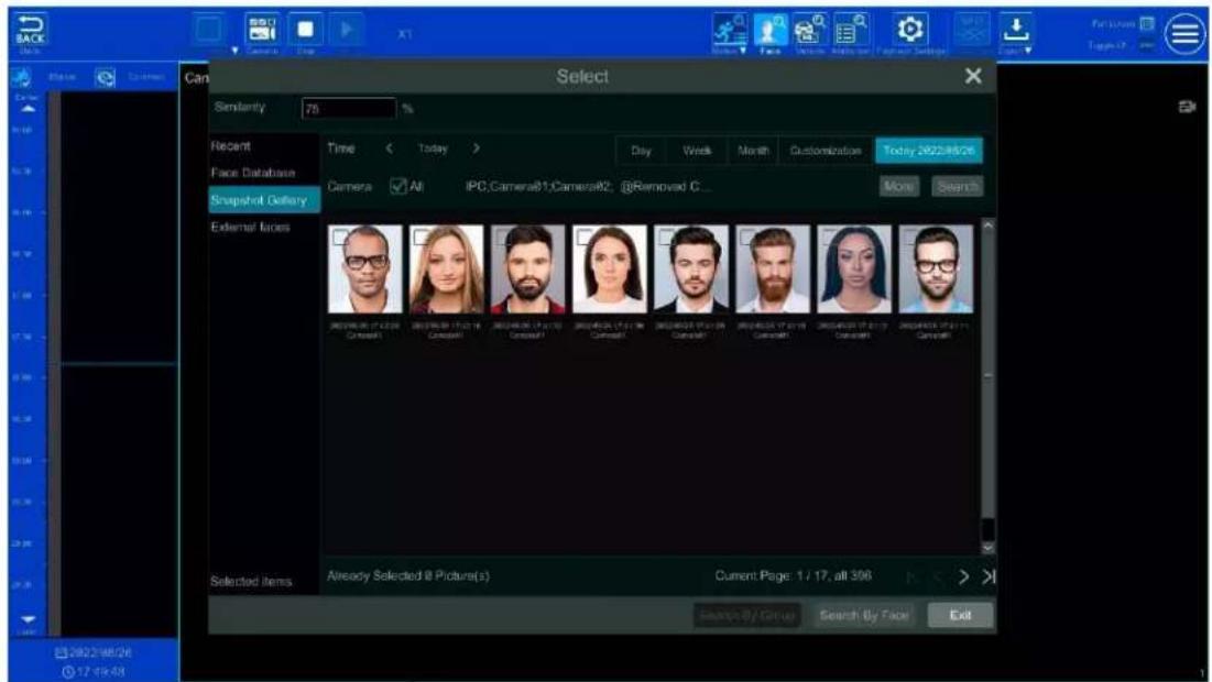
① Set similarity. The higher the sensitivity value is, the lower the searching accuracy is, and vice versa.
② Select targets. You can select targets from recent, face database, snapshot gallery or external faces.
③ Select search mode. There are two search modes: search by group and search by face.
Search by group: Choose "Face Database" and then click "More" to choose one or more groups.
Move the cursor to the me block where the record exists and click to play those records.
You can only check "Face" to view the face records.
8.3.4 Smart Search by License Plate
Before starng smart search by plates, please add ANPR cameras rst and then enable the LPR funcon. Please refer to License Plate Recognition secon for details.
Click buon to go to the following interface:

Select the plate from "Recent", "Plate Database" or "Customizaon" and then click "Search" to search recorded les and play. Here is an example of plate search from "Plate Database".
Click to choose a group. Then plates will be listed in the table automacally. Click "Search" to play.
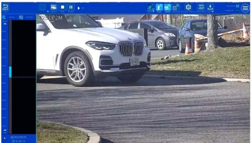
natural_image
Exterior view of a white BMW SUV parked on a paved lot with parked cars and pavement (no visible text or symbols)8.3.5 Smart Search by Object Aributes (BETA)
PLEASE NOTE THIS FUNCTIONALITY IS STILL IN BETA AND MAY HAVE SOME INACCURACIES.
Before searching for objects by aributes, you must enable the video metadata (BETA) funcon of the camera. Please note that this funcon will only work with specic cameras running the newest rmware. Check with Speco Technologies' technical support for models and firmware. Click

to select the aributes. Select the aributes of human/motor vehicle/non-motor vehicle as needed to search the results.

8.4 Record Search, Playback & Export
The record data and the captured pictures can be exported through the network or USB (U disk or USB mobile HDD). The le system of the export devices should be FAT32 format.
8.4.1 EZ Search
① Click Start→Search and Export→EZ Search to go to the "EZ Search" tab. There are two view modes: by me and by camera. In the me view mode, a maximum of 64 camera thumbnails can be showed. If the camera thumbnail number is more than 64, the cameras will be listed directly by their camera name, not the thumbnail. A maximum of 196 camera names can be listed. If the camera names exceed 196, the me view mode will be disabled and only the camera view mode will be available.

② Select one camera in the interface and then click "Open" buon.
③ Click the image box to play the recording in the small playback box on the le side of the interface (the box which has image inside indicates that the recording data exists).
④ Refer to the picture below. Drag the color blocks on the me scale to select the recording data and then click the "Export" buon to open the "Record Backup" window as shown below. Select the device name, backup format and path and then click "Export" buon to start the backup.
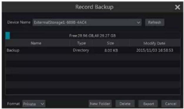
Note: If you back up the record in private format, the system will back up a RPAS player to USB device automatically. The private format record can be played by RPAS player only.
⑤ Click "Playback" buon to play the record in the playback interface (refer to 8.2 Playback Interface Introducon for details). Click "Exit" to exit the interface.

Time Slice Search:
Method One: Click "Year", "Month" or "Day" buon under the record me scale to select the me slice mode. In "Day" mode, click the le/right side of the me scale to view the record of the last/next day; click "Minute" in the "Picture" opon under the me scale to select "Minute" mode (in "Minute" mode, click the me scale to change the me of the 60 display windows) and click "Hour" to select "Hour" mode.
Method Two: Click > beside "Camera Thumbnail" on the le top corner of the interface to select the me slice mode.
Method Three: Right-click the mouse on any area of the me-sliced interface to go back to the upper interface.
8.4.2 Time Search
① Click Start→Search and Export→Time Search to go to the "Time Search" tab as shown below.
② Click + on the boom of the interface to add playback camera. A maximum of 16 cameras can be added for playback. Click "Modify" on the top right corner of the camera window to change the camera and click "Clear" to remove the camera.
③ Click the camera window to play the recording in the small playback box on the le side of the interface. You can set the date on the top le of the interface, check the event type as required and click the time scale or click under the me scale to set the me. The camera window will play the record according to the me and event type you set.
④ Drag the color blocks on the me scale to select the record data (or click "Set Backup Time" buon on the boom le corner of the interface to set the backup start me and end me) and then click "Export" buon for record backup. Click "Playback" buon to play the record in the playback
interface.

8.4.3 Event Search
① Click Start→Search and Export→Event Search to go to "Event Search" tab as shown below.
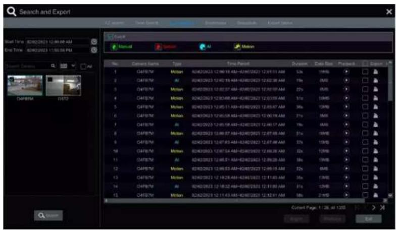
② Check the event type in the interface as required.
③ Click 📊 to set the start me and end me on the top le of the interface.
④ Check specific cameras on the le side of the interface or check "All" to select all the cameras and then click searched record will be displayed in the list.
⑤ Click ▶ in the list to play back the record in the popup window. Click ▶ to back up one record data or check mulple record data in the list and then click "Backup" buon for record batch backup.
⑥ Select one record data in the list and then click "Playback" buon to play the record in the playback interface.
8.4.4 Bookmark Search
Only if you add tags can you play the recording by tag search. Click Start→Playback to go to the playback interface and then click 📄 on the boom of the camera window to add bookmarks when you want to mark the playback me point of the selected camera.
Click Start→Search and Export→Bookmarks to go to "Bookmarks" tab.
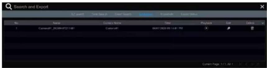
Click in the interface to play the record. Click to edit the tag name. Click to delete the tag.
8.4.5 Snapshots
Click Start→Search and Export→Snapshots to go to "Snapshots" tab. The system will display all the captured images automatically in the list.

Click 📄 to delete the image. Click 📋 to open the "Export" window. Select the device name and save path in the window and then click "Save" buon.
Click 📄 to open the "View Image" window. Click 📋 to export the image. Click 🖱 to view the previous image; click ➕ to view the next image; click 🔒 to delete the image; click ➔ to play all the images.

8.4.6 View Export Status
Click Start→Search and Export→Export Status or click 📄 on the tool bar at the boom of the playback interface to view the export status.
9 AI Event Management
9.1 Face Recognition
Only some models support alarm trigger based on face comparison. If your device doesn't support face recognition funcon, please skip the face database and face recognition instrucons.
The following are instrucons on how to set up the Face Recognition funcon for the rst time:

flowchart
graph LR
    A["Set face detecon and alarm linkage"] --> B["Add face group"]
    B --> C["Add faces to the face group"]
    C --> D["Enable and set successful recognition"]
    E["(or stranger)"] --> F["Set successful recognition (or stranger) alarm linkage"]
9.1.1 Face Detecon Sengs
Face Detecon: Alarms will be triggered if someone intrudes into the pre-dened alarm areas.
① Click Start→Setngs→AI/Event→AI Event→Face Recognition→Detecon to go to the following interface:

② Select the camera, check "Enable Detecon by IPC" and set the duraon.
Note: Some models may support face detecon by NVR. For these models, the camera without AI funcon also can be added and used to detect faces through the NVR. However, if face detecon by NVR is enabled for a camera (without AI), people/vehicle perimeter detecon cannot be enabled simultaneously, and vice-versa.
③ Set the schedule. Click "Manage" to set the desired schedule. Please refer to 7.1.2 Schedule Sengs for details.
④ Set the snapshot interval and snapshot number. The snapshot interval refers to the me interval that the camera captures the same face during its connuous tracking period. The snapshot number refers to the picture number of the same face captured during its connuous tracking period (For example: the snapshot interval is set to "30 seconds" and the snapshot number is set to "3"; then the camera will capture the same face once every 30 seconds and it will capture this face 3 mes at most during its connuous tracking period).
⑤ Enable face match exposure as need. When the brightness of the captured face is not enough, it can be enabled. (Only some IPCs support this funcon)
⑥ Set the alarm area. Drag the mouse to draw a detecon area. Click "Clear" to delete the alarm area. Then set the detectable face size by dening the maximum value and the minimum value (The default size range of a single face image occupies from 3% to 50% of the enre image).
⑦ Enable "Original picture" or/and "Target picture" as needed. If enabled, the system will automatically save the corresponding images on the SD card.
⑧ Click "Apply" to save your sengs.
⑨ Click "Trigger Mode" to go to face detecon alarm linkage sengs interface:
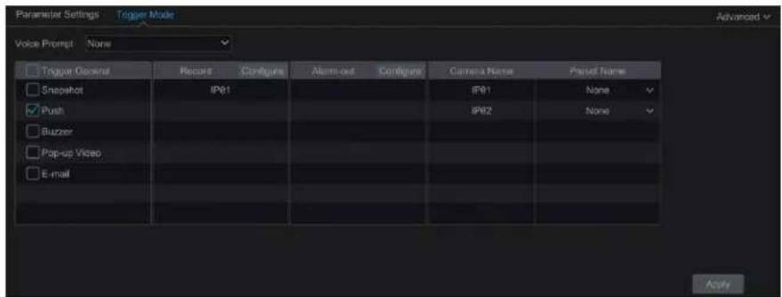
Face Detecon Alarm Linkage Conguraon:
① Trigger "Record", "Snapshot", "Push", "Alarm-out", "Preset", "Buzzer", "Pop-up Video" and "E-mail" as needed.
Record: Click the "Congure" buon to open that window. Select a camera on the le side and then click let the camera as the trigger camera. Select a trigger camera on the right side and then click to cancel the trigger camera. Click "OK" to save your sengs. The trigger cameras will record automatically when faces are detected.
Alarm-out: Click the "Congure" buon to open that window. The "Trigger Alarm-out" window will then pop up automacally. Congure the trigger alarm-out in that window. The system will trigger the alarm-out automacally when faces are detected. You need to set the delay me and the schedule of the alarm outputs. See 11.6.1 Alarm-out for details.
Preset: Click ▼ and then select the preset for each camera. To add presets, please see 6.2 Preset Sengs for details.
Snapshot: If it is enabled, the current camera will capture images automatically when faces are detected.
Push: If it is enabled, the system will send messages when faces are detected.
Buzzer: if it is enabled, the system will begin to buzz when faces are detected. To set the delay me of the buzzer, please see 11.6.4 Buzzer for details.
Pop-up Video: if it is enabled, the system will open the corresponding video automatically when faces are detected. To set the duraon me of the video, please see 11.6.3 Display for details.
E-mail: if it is enabled, the system will send an e-mail when faces are detected. Before you enable the email, please conjure the recipient's e-mail address (see 11.6.2 E-mail for details).
Enable "IPC_Digital Deterrent" or "IPC_Light" as needed (only specific IPCs support these two funcons). To set the IPC voice and its mes and volume, please refer to 11.6.6 Digital Deterrent for details. To set the light ashing me and frequency of the IPC, please refer to 11.6.7 Light for details.
⑩ Click "Apply" to save your seings.
9.1.2 Face Database Management
This funcon is only available for the N8NRE/N16NRE/N32NRE.
① Click Start→Sengs→AI/Event→AI Event→Face Recognition→Face Database to go to the following interface:

For the initial setup, click "+" or "Add Group" to add groups.
② To add targets for each group select a list and then click √ to expand the list as shown below.
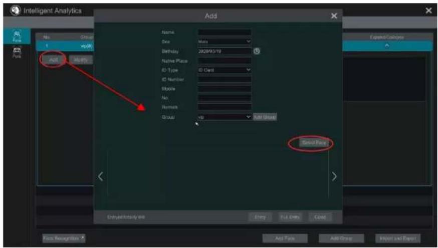
② Click "Add" and then click "Select Face" to add face images. You can add faces from the snapshot gallery or add external faces.
Adding faces from snapshot gallery: Select search me or self dene the search me and then click "Search" to search target faces. Next, select the desired faces and click "Select".
Note: The picture marked with a green icon can be added to the face database. Those that can't likely have resolution issues.

Add external faces
Save the face pictures on your USB storage device and then insert the USB storage device into the USB port of the NVR.
Go to the face database interface. Click 📋 to expand the group and then click "Add". Select "External faces" to select face pictures. You can select one face to add or mulple faces to add.
To add mulple faces: a. put face pictures and the descripon le (.csv or .txt) to one specie folder (please edit the detailed descripons of these pictures according to the personal informaon descripon); b. click "All" to select all face pictures; c. click "Full Entry".
Note: the added image must be less than 70KB and the image format should be ".jpg" and ".jpeg".
③ Aer that, add the corresponding informaon, like name, gender, birthday, ID number, phone number and so on.
Having saved the target image, click the image and then the detailed informaon will be listed on the right.

④ Import and Export Face database
Insert your mobile storage device into the USB interface of the NVR and then click "Import and Export" to import or export the face database sengs.
The exported face database le (cvs+jpg) can be directly imported to the face database to make it very convenient for you to transfer one NVRs face database le to other NVRs.
9.1.3 Face Recognition Sengs
This funcon is only available for the N8NRE/N16NRE/N32NRE.
Aer the face database and face pictures are added, click "Face Recognition" to return to the face recognition setup interface. Click the "Recognition" tab to go to the following interface:

① Enable "Successful Recognition" or "Stranger". Click "Parameter Sengs" to set the similarity of the matching face group.
Disable live display: if checked, the live view interface (target detecon tab) will not display captured faces in real me.
② Set the alarm linkage items for successful recognition.
- Select one or more face groups and then choose the schedule. Click "Manage" to set the schedule.
- Set the text prompt and voice prompt. When the captured face is matched successfully, the text will appear on the right of the live view
interface and broadcast the audio.
● Enable alarm output pulse (access control).
- Trigger record, snapshot, alarm-out, buzzer, push, pop-up video, E-mail and pop-up message box as needed. The alarm linkage sengs are similar to the face detecon alarm (see 9.1.1 Face Detecon Sengs for details).
- Click "Apply" to save your settings.
③ Set the stranger alarm linkage items. When the captured face picture doesn't match the face pictures in the face database or their similarity is lower than the set value, the captured person will be regarded as a stranger.

- Congure the schedule
- Set the text prompt and voice prompt. The text will show on the captured picture and the voice will be broadcasted when detectng a stranger.
- Trigger record, snapshot, alarm-out, buzzer, push, pop-up video, E-mail and pop-up message box as needed. The alarm linkage sengs are similar to the face detecon alarm (See 9.1.1 Face Detecon Sengs for details).
- Click "Apply" to save your settings.
④ Click "+" to add more successful recognition tasks. Select the added task and then click "-" to delete it.
9.2 License Plate Recognition
Please add an LPR camera before using this funcon. If your camera doesn't support this funcon, please skip the following instrucons. When seng up an LPR for the rst me, please use the following procedures:

flowchart
graph LR
    A["Enable and set plate detecon"] --> B["Add plate group"]
    B --> C["Add plates to the plate group"]
    C --> D["Enable license plate recognition"]
    E["Set successful recognition (or strange plate) alarm linkage"] --> C
9.2.1 License Plate Detecon Sengs
Click Start→AI/Event→AI Event→LPR to go to the interface below. Select an ANPR camera and click the "Detecon" tab shown below.
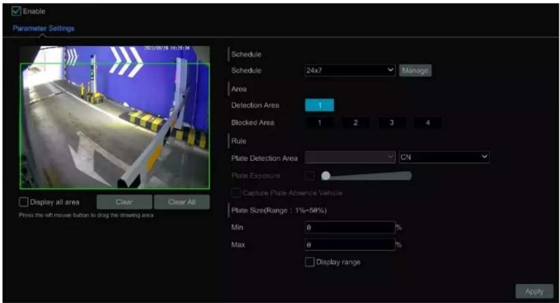
- Set the schedule.
- Set the area and plate exposure as needed.
Set the alarm area. Drag the mouse to draw a detecon area. Click "Clear" to delete the alarm area.
Set the blocked area. Select the number and then draw a blocked area. Up to 4 areas can be set up. Aer you set the blocked area, this area will not be detected.
Click "Display all area" to view all blocked and detecon areas.
Click "Clear All" to clear all blocked and detecon areas.
- Check "Capture plate absence vehicle" as needed.
- Set the plate size by dening the maximum value and the minimum value (The default size range of a single plate occupies from 5% to 50% of the enre image).
● Display range: if enabled, the set maximum detecon box and the minimum detecon box can be displayed on the le window. - Click "Advanced" to set the recognition mode as needed (only some LPR cameras support).
9.2.2 Plate Database Management
In the LPR interface, click the "Plate Database" tab to go to the plate database management interface shown below. For the rst me, you can click "+" or "Add Group" to add groups.
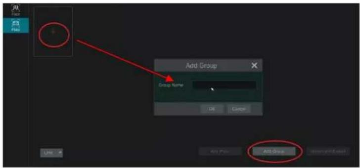
Add plates to each group:
① Click ▼ to extend the group. Click "Add Plate" to open the following window:

② Enter the plate, vehicle owner and mobile phone number.
③ Select the vehicle type and group.
④ Enable validity period to set the start and end me
⑤ Finally click "OK" to complete.
Select the added plate and then click 📄 to modify its informaon; click 📄 to delete this plate. The plates can be imported and exported in bulk by clicking "Import and Export". You can click "Plate Informaon Descripon" to view the detailed informaon about how to import or export the plate list.
9.2.3 License Plate Recognition Sengs
① In the LPR interface, click the "Recognition" tab. Then enable "Successful Recognition" or "Strange Plate".

② Set the successful recognition alarm linkage.
- Select one or more plate groups and then choose the schedule. Click "Manage" to set the schedule.
- Set the text prompt. When the captured plate is matched successfully, the text will appear on the right of the live view interface.
● Enable alarm output pulse (access control). - Trigger record, snapshot, alarm-out, buzzer, push, pop-up video, E-mail and pop-up message box as needed. The alarm linkage sengs are similar to the face detecon alarm (See 9.1.1 Face Detecon Sengs for details).
③ Set the strange plate alarm linkage. When the captured plate picture doesn't match the plates in the plate database or their similarity is lower than the set value, the captured plate will be regarded as a strange plate.
9.3 Line Crossing Detecon
Line Crossing Detecon:
Alarms will be triggered if the people or vehicles cross the pre-dened alarm line.
① Click Start→Sengs→AI/Event→AI Event→Line Crossing to go to the following interface:

② Select the camera, enable line crossing detecon by IPC and set the duraon.
③ Set the schedule.
④ Select the direcon.
Direcon: A<->B, A->B and A<-B oponal. It is the crossing direcon of the target that crosses over the alert line.
A<->B: the alarm triggers when the target crosses over the alert line from B to A or from A to B.
A->B: the alarm triggers when the target crosses over the alert line from A to B.
A<-B: the alarm triggers when the target crosses over the alert line from B to A.
⑤ Draw line. Refer to the interface shown above. Drag the mouse in the image to draw an alert line. Click the "Clear" to delete the alert line.
⑥ Click "Detecon Target" to choose the detecon target and the sensitivity. The detecon target includes people, vehicle and non-vehicle. Only some IPCs can detect human or vehicle separately. If the camera doesn't support this funcon, please skip this step.
⑦ Click "Advanced" to choose "Original picture" or "Target picture" on the SD card of the camera. (If your camera doesn't support this funcon, please skip this step).
⑧ Click "Trigger Mode" to congregate tripwire alarm linkage items.
- Enable or disable "Record", "Snapshot", "Push", "Alarm-out", "Preset", "Buzzer", "Pop-up Video" and "E-mail". The alarm linkage sengs are the same as the face detecon alarm (see 9.1.1 Face Detecon for details).
- Enable "IPC_Digital Deterrent" or "IPC_Light" as needed (only some IPCs support these two funcons). To set the IPC voice and its mes and volume, please refer to 11.6.6 Digital Deterrent for details. To set the light ashing time and frequency of the IPC, please refer to 11.6.7 Light for details.
⑨ Click "Apply" to save your sengs.
9.4 Intrusion Detecon
Intrusion Detecon Conguraon:
Alarms will be triggered if the people or vehicles intrude into the pre-dened area.
① Click Start→Sengs→AI/Event→AI Event→Intrusion to go to the interface below.
② Select the camera, enable the intrusion detecon by IPC and set the duraon.
③ Set the schedule.
④ Select regional advies. "Appear" or "Cross" can be selected (if your camera doesn't support region entrance/exing detecon, "Cross" will not be enabled). If "Cross" is selected, you can choose the crossing direcon.
⑤ Select the alarm area. Up to 4 alarm areas can be set up.
⑥ Draw the alarm area of the intrusion detecon. Refer to the interface shown below. Click around the area where you want to set as the alarm area in the image (the alarm area should be a closed area).

⑦ Click "Detecon Target" to choose the detecon target and the sensitivity. The detecon target includes people, vehicles and non-vehicles.
⑧ Click "Trigger Mode" to conjure intrusion detecon alarm linkage items.
- Enable or disable "Record", "Snapshot", "Push", "Alarm-out", "Preset", "Buzzer", "Pop-up Video" and "E-mail". The alarm linkage sengs are the same as the face detecon alarm (see 9.1.1 Face Detecon Sengs for details).
- Enable "IPC_Audio" or "IPC_Light" as needed. (only some IPCs support these two funcons). To set the IPC voice and its mes and volume, please refer to 11.6.6 Digital Deterrent for details. To set the light ashing me and frequency of the IPC, please refer to 11.6.7 Light for details.
⑨ Click "Copy To" to copy all sengs to other cameras.
⑩ Click "Apply" to save your seings.
9.5 Abandoned/Missing Object Detecon
① Click Start→Sengs→AI/Event→AI Event→Object Abandoned/Missing to go to the interface below.
② Set the schedule
③ Select the camera, enable the object detecon, and set the duraon and detect type. There are two detecon types: Abandoned object and missing object.
Abandoned object: Alarms will be triggered if there are arcs le in the pre-dened detecon area.
Missing object: Alarms will be triggered if there are arcs missing in the detecon area drew by the users.
④ Select the alarm area and area name. A maximum of 4 alarm areas can be set.
⑤ Draw the alarm area of the object detecon. Refer to the interface shown below. Click around the area where you want to set as the alarm area in the image (the alarm area should be a closed area). Click the "Clear" buon to delete the alarm area.
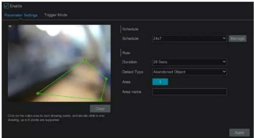
⑥ Click "Trigger Mode" to congregate abandoned/missing object detector alarm linkage items. Enable or disable "Record", "Snapshot", "Push", "Alarm-out", "Preset", "Buzzer", "Pop-up Video" and "E-mail". The alarm linkage sengs are the same as the face detector alarm (see 9.1.1 Face Detecon Sengs for details).
⑦ Click "Apply" to save your seings.
9.6 Crowd Density Detecon
Only some IPCs may support this funcon.
Crowd Density Conguraon:
Alarms will be triggered if the crowd density exceeds the set threshold value in the pre-dened area.
① Click Start→Sengs→AI/Event→AI Event→Crowd Density to go to the interface below.

② Select the camera, enable crowd density detector and set the schedule, duraon, refresh frequency and alarm threshold.
Refresh Frequency: Refers to the refresh me of the detecon result report.
Alarm Threshold: Alarms will be triggered once the percentage of the crowd density in a specified area exceeds the pre-dened threshold value.
③ Select the alarm area. Draw the alarm area for the crowd density detecon. Refer to the interface shown below. Check "Draw Area" and then drag the mouse to draw a rectangular area. Uncheck the "Draw Area" when you are nished. Click the "Clear" buon to delete the alarm area.
④ Click Trigger Mode to congregate crowd density detection alarm linkage items. Enable or disable "Record", "Snapshot", "Push", "Alarm-out", "Preset", "Buzzer", "Pop-up Video" and "E-mail". The alarm linkage signals are the same as the face detection alarm (see 9.1.1 Face Detection Sengs for details).
⑤ Click "Apply" to save your seings.
9.7 Target Counng
Only some IPCs support this funcon.
● People counng in the pre-dened area:
This funcon is used to detect, track and count the number of people entering or exiting a selected area on a video.
Note: Only specific IPCs support this funcon.
① Click Start→Setngs→AI/Event→AI Event→Target Coung to go to the interface below.
② Select the camera, enable target counting detector and set the schedule, duraon, sensitivity, stasc cycle, enter threshold, departure threshold and retenon threshold.
Stasc cycle: Opons of Always, daily, weekly and monthly.
Manual Reset: The current number of people counted will be cleared and the stasc cycle will restart when you click the "Manual Reset" buon.
③ Set the alarm area and entrance direcon. Click "Draw Area" and drag the mouse to draw a rectangular area. Drag the rectangle to change its position. Uncheck the "Draw Area" when you are nished drawing. Click "Clear" to clear the area. Click and drag the arrow or the other end of the arrow line to change the direcon people enter.
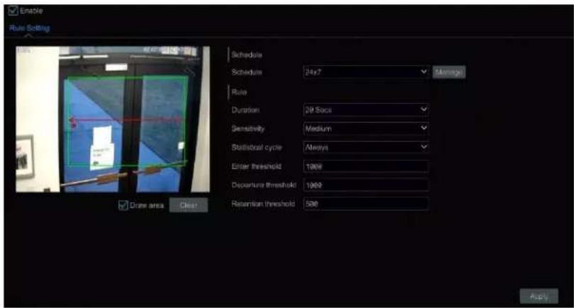
⑥ Click "Apply" to save your seings.
● Human/Motor Vehicle/Non-Motor Vehicle Counng
The informaon of human/motor vehicle/non-motor vehicle can be calculated and sent by day, by week and by month, so that you can receive and analyze these stascs on me.
Only some IPCs support this funcon. If your camera doesn't support this funcon, please skip the following instrucons.
① Click Start→Setngs→AI/Event→AI Event→Target Coung to go to the following interface:

② Enable line crossing counng.
③ Set the schedule.
① Drag the mouse on the small window to draw the line you want crossed. Click "Clear" to delete the alert line.
Direcon: A->B and A<-B are oponal. It is the direcon of the target that crosses over the alert line.
⑤ Check "Stascal OSD" and the stascal informaon will be displayed on the live view interface.
⑥ Set the reset informaon. You can set reset informaon manually or enable "Auto Reset" as needed.
⑦ Click the "Detecon Target" tab to set the detecon target, including people, vehicles (Cars, trucks, etc.) and non-vehicles (bicycles, Motorcycles, etc.).
⑧ Click "Advanced" to open the window below. You can select "Original picture" or "Target picture".
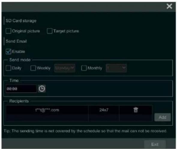
In the interface above, you can send e-mail to a specied person on a daily/weekly/monthly basis regarding the target counng. Click "Add" to add the recipient, and then enable "Send Email" and select "Send mode" and me.
⑨ Click "Apply" to save your sengs.
9.8 Tampering Detecon
Tampering Detecon Conguraon:
① Click Start→Setngs→AI/Event→AI Event→Tampering to go to the following interface:

② Select the camera and detecon duraon and then enable the relevant detecon as needed.
Scene Change: Alarms will be triggered if the scene of the monitor video has changed.
Video Blurred: Alarms will be triggered if the video becomes blurry.
Video Color Cast: Alarms will be triggered if the video becomes obscured.
③ Set the sensitivity of the excepon detecon.
④ Click "Trigger Mode" to congregate exception alarm linkage items. Enable or disable "Record", "Snapshot", "Push", "Alarm-out", "Preset", "Buzzer", "Pop-up Video" and "E-mail". The alarm linkage sengs are the same as the face detecon alarm (see 9.1.1 Face Detecon Sengs for details).
⑤ Click "Apply" to save your sengs.
9.9 Fire Detecon
Fire detecon is only available if you are using the appropriate Speco Technologies' Thermal Camera. Please note this is only intended as a supplement to ocial re detecon methods and should not be relied on as a primary alert source.
Fire Detecon: Alarms will be triggered if the camera detects a re source through the thermal imaging.
① Click Start→Sengs→AI/Event→AI Event→Fire Detecon to go to the following interface:
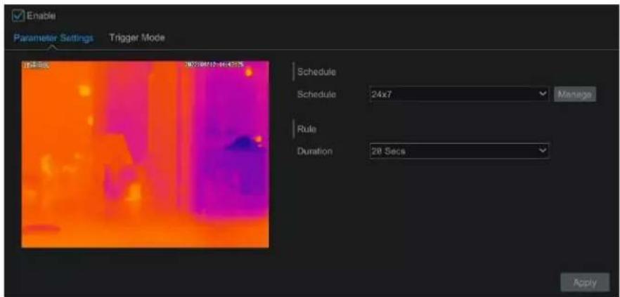
② Set the schedule and the alarm duraon time.
③ Click "Trigger Mode" to congregate exceed alarm linkage items. Enable or disable "Record", "Snapshot", "Push", "Alarm-out", "Preset", "Buzzer", "Pop-up Video", "Pop-up Message Box" and "E-mail". The alarm linkage sends are the same as the face detection alarm (see 11.1 Sensor Alarm for details).
④ Click "Apply" to save your sengs.
9.10 Temperature Detecon
Temperature Detecon is only available if you are using the appropriate Speco Technologies' Thermal Camera.
Temperature Measurement: When a temperature of the pre-dened point/line/area exceeds the temperature threshold value, alarms will be triggered.
① Click Start→Sengs→AI/Event→AI Event→Temperature Detection to go to the following interface:

② Set the schedule and the alarm duraon time.
③ Set thermography rule. Select the rule type, including Point, Line and Area.
Emissivity: Set the emissivity of the target. The emissivity of each object is different.
Distance: The distance between the target and the camera.
Reected temperature: If there is any object with high emissivity in the scene, set the receive temperature to correct the ambient temperature.
The reeeve temperature should be set the same as the temperature of the high emissivity object.
Set the alarm rule, alarm temperature and alarm output. For example, select Alarm Rule as Above (Average Temperature), set the alarm temperature to 100^ C and check alarm output. Alarms will then be triggered when the average temperature of the target is higher than 100^ C.
④ Set the point, line or area on the small window.
Point setup: Aer the type is set to "Point", click on the image to set the point. Up to 10 points can be set in the above interface.
Line setup: Aer the type is set to "Line", drag the mouse on the image to draw a line. To ensure the accuracy of temperature measurement, it is recommended to set not more than two lines at the same me.
Area setup: Click around the area where you want to set as the alarm area on the image (the alarm area should be a closed area). To ensure the accuracy of temperature measurement, it is recommended to set not more than two areas at the same me.
⑤ Click "Trigger Mode" to congregate exceed alarm linkage items. Enable or disable "Record", "Snapshot", "Push", "Alarm-out", "Preset", "Buzzer",
"Pop-up Video", "Pop-up Message Box" and "E-mail". The alarm linkage sengs are the same as the face detecon alarm (see 11.1 Sensor Alarm for details).
⑥ Click "Apply" to save your sengs.
9.11 Video Metadata (BETA)
Please note that this feature is sll in BETA and is not recommended for ocial implementation into your security environment.
Video Metadata (BETA): Humans, motor vehicles and non-motor vehicles in the video can be classified, counted and captured and the relevant features can be extracted and displayed on the live interface.
① Click Start→Setngs→AI/Event→AI Event→Video Metadata (BETA) to go to the following interface:

② Enable Video Metadata (BETA) and then set the schedule.
③ Set the detecon area and any blocked areas.
Detecon Area: 4 detecon areas can be set. Targets that enter the pre-dened detecon area will be counted and captured.
Blocked Area: 4 blocked areas can be set. Targets that enter the pre-dened blocked area will not be counted or captured.
To set a detecon area: Select the number and then set the detecon area. Click around the area you want to set as the alarm area on the image (the alarm box should be a closed area).
To set blocked area: Select the number and then set the blocked area. The setup steps are the same as detecon area seings.
Display OSD: If enabled, you can see the stascal informaon of humans, motor vehicles and non-motor vehicles on the screen. The stascal OSD informaon can be customized as needed.
④ Set the reset informaon. Auto reset or manual reset can be set as needed.
⑤ Advanced sengs. Click "Advanced" to enter the advanced sengs interface. Select the recognition mode as needed. Interval mode and instant mode can be selectable.
Interval mode: the system will push the captured picture to the live interface according to the set interval me.
Instant mode: the system will push the captured picture immediately once a target is detected.
⑥ Set the detecon target and sensitivity.
⑦ Select the aribute informaon of the target. When the target is detected, the informaon you select will be displayed under the captured image.
⑧ Click "Apply" to save your sengs.
10 Intelligent Analycs
10.1 Target Detecon View
10.1.1 Human Body/Vehicle Detecon View
This feature only works with the appropriate Speco Blue cameras. The setup steps are as follow:
① Enable the line crossing/Intrusion/Target counting function of IPCs/NVR, draw the line or area and choose the detector target (see 9.3 Line crossing Detecon and 9.4 Intrusion Detector for details).
② Go to live view interface and then click 📄 to go to the target detecon interface of this channel. In this interface, you can switch the channel on the top right. You can also choose the target detecon tab on the le panel of the live view interface to go to the target detecon interface of mul-channel shown below. Note that only some models support mul-channel target detecon funcon. Click the captured picture on the right of the live interface to see detailed snapshot informaon such as snapshot me, camera, event type and target type.

Click "More" to see a dropdown list. You can export the captured pictures by clicking "Export" or view the target ID by clicking "Informaon". Click "Search" to go to smart human body/vehicle search interface. The system will automatically search captured people/vehicles. Click "Playback" to go to the playback interface.
10.1.2 Face Detecon/Match View
Only face recognition NVRs (8/16/32NRE) support the funcons in this secon. If your NVR doesn't support these features, you can skip the following instrucons.
The setup steps are as follow:
① Enable face detecon funcon (see 9.1.1 Face Detecon Sengs for details).
② Enable face recognition funcon and set the alarm linkage items (see 9.1.3 Face Recognition Sengs for details).
③ Go to live view interface and click on a face detecon channel. This will open a toolbar under the channel. Next, click to go to the target detecon interface of this channel. In this interface, you can switch the channel on the top right.

For unknown faces, you can select one and click ✕ under the captured face to register this face (see the picture below); click 🔒 to quickly go to the smart face search interface where you can search for matching facial informaon; click ▶ to quickly go to the smart face playback interface; click ▶ view snapshot details.

Before registering pictures of target faces, please create groups for them in advance (see 9.1.2 Face Database Management for details). Aer the pictures are registered, your system will compare them automatically the next me the corresponding faces are captured. Refer to the following picture:
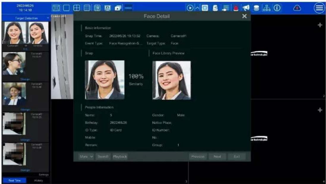
Double click a face picture to see details of the snapshot such as the snapshot picture, original image, snapshot me and camera. Click "more" and a dropdown list will display with more opons. Click "Register" to register the current snapshot. Click "Search" to go to the face search interface. Click "Playback" to go to the playback interface. Click "Export" to export the details of this snapshot. Click "Informaon" to view face ID.
In the face match interface, click "Sengs" to open the following window:

Target Detecon Display: Face, human body, vehicle or plate can be enabled. If disabled, the captured target picture will not be displayed under the target detecon tab in the live view interface.
Display Strategy: Two opons: Comparison priority and only comparison
Video Overlay Display:
If "Target box" is clicked, you will see the target traced by a lile red box.
If "Rule Line and Area" is checked, you will see the rule lines for line crossing detecon and detecon area of intrusion detecon displayed on the screen. You can select the color of the rule line and area as needed.
When a captured face picture is successfully recognized, click the picture on the right to open a face detail window as shown above. In this window, you can see the captured face picture, the matched picture from the face library and the relevant informaon. You also can view the original image, search image by snapshot, play back by snapshot and export the face details by clicking "More" buon.
Additionally, you can view the history of captured face pictures and face match informaon in the face match interface by clicking the "History" tab. Besides registering face pictures in the live view interface, you can also add target face pictures to the face database interface.
Note: if you enter a remark when adding a face picture to the face database, that informaon (instead of the person's name), will be shown under the picture aer a successful recognition.
10.1.3 License Plate Detecon/Recognition View
License plates can only be captured and matched if a compatible Speco Blue ANPR camera is added and enabled. The setup steps are as follows:
① Enable the Plate Detecon funcon (See 9.2.1 License Plate Detecon Sengs for details).
Once enabled, you can see the captured plates displayed in the live view interface shown below:

Put the cursor on the captured plate picture and then click 🧑 to register this plate as shown below:

Click 🧑️ to view the captured detail informaon. Click 🔒 to quickly enter the vehicle search interface. You can search the matched plate informaon in this interface. Click ➤ to go to the smart playback interface.
② Enable the License Plate Recognition funcon and set the alarm linkage items (see 9.2.3 License Plate Recognition Sengs for details).
③ Go to the live view interface and click 📋 on the top right corner. Next, choose the Target Detecon tab to go to the mul-channel target detecon interface shown below. When a plate is captured, it will be displayed on the right panel. A strange plate will show "Strange plate" under the plate picture.
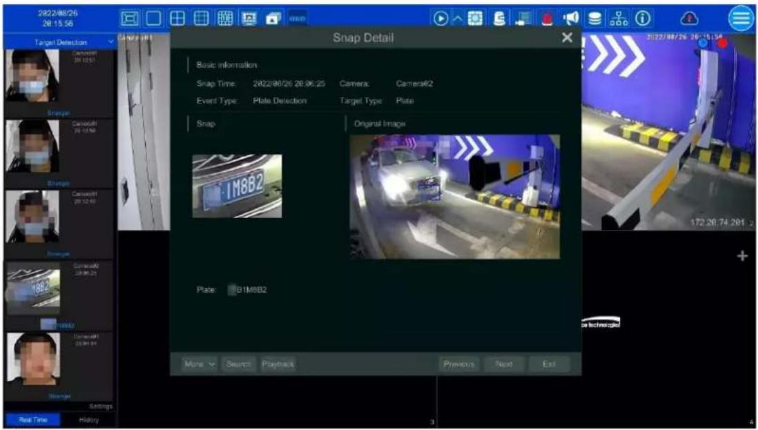
Click the captured plate picture to open a detailed informaon window. You can view the snapshot picture, original picture, snapshot me, camera, etc. Click "More" to view the ID informaon of the target and export the captured picture. Click "Search" to go to the vehicle search interface. Click "Playback" to go to the playback interface.
10.1.4 Object Aribute View (BETA)
① Enable the Video Metadata (BETA) funcon and then select the detecon target and display arbutes (see 9.11 Video Metadata (BETA) for details). ② Go to live view interface and click on an AI camera channel (where video metadata funcon is supported). This will bring a toolbar under the channel. Then click to go to the target detecon interface of this channel. In this interface, you can switch the channel on the top right.
Click "Sengs" at the boom right to select the aribute informaon of people/motor vehicle/non-motor vehicle you want to view under the captured picture.
Click the captured picture to view its details. In the detail interface, you can view the captured picture, original picture, object arbutes, etc.
10.2 Smart Search
10.2.1 Face Search
Only some models support this funcon. You can skip the following instrucons if your device doesn't support Face Search.
Face Search by Event
① Click Start→ Intelligent Analycs → Search→ Face to go to the following interface:

② Click ▼ to choose a face detecon camera.
③ Select all events, successful recognition, or stranger.
④ Click "Search" to search all face pictures. You can view face pictures by me or by camera.
⑤ Click the searched face picture to play in the small playback window; select a face picture and click "Backup" to export it.
Click "Original" to see the original image shown below.
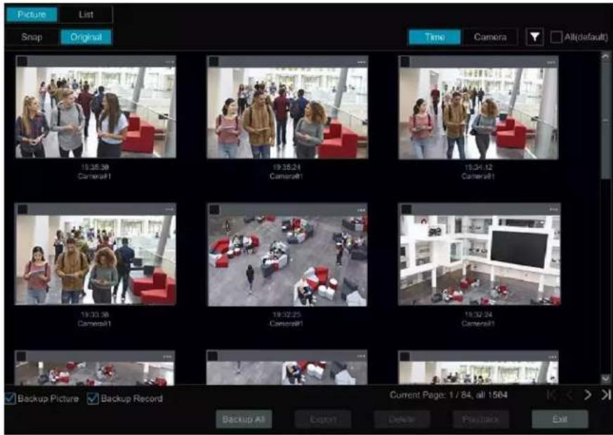
Click "List" to view the snapshot informaon list. Click
to view the detail informaon; click
to back up the image.
Face Search by Face
In the face picture search interface, click "By Face" to go to the interface shown below.
① Click + to add a target face which can be searched and added from recent, face database, snapshot gallery and external faces. A single face picture or mulple face pictures can be added and searched.

To add a single target face from recent faces:
a. Choose the face.
b. Click "Select Face".
To add a single target face from the face database:
a. Click "More" to choose groups.
b. Select a target face and click "Select Face".
To add a single target face from the snapshot gallery:
a. Select me and click "More" to choose cameras.
b. Click "Search".
c. Check a face and click "Select Face".
To add a single target face from external faces:
a. Save the target face to the mobile storage device and then insert this device into the USB interface of your NVR.
b. Select "External Face" to import the face via this interface.
② Set similarity and then click "Search".
③ Click the searched image to play records in the small window.
④ Select the searched image and click "Backup Picture" or "Backup Record". Then click "Backup" to build backups for pictures or records.

• View Image by List
Click "List" tab to view images by me as shown below.
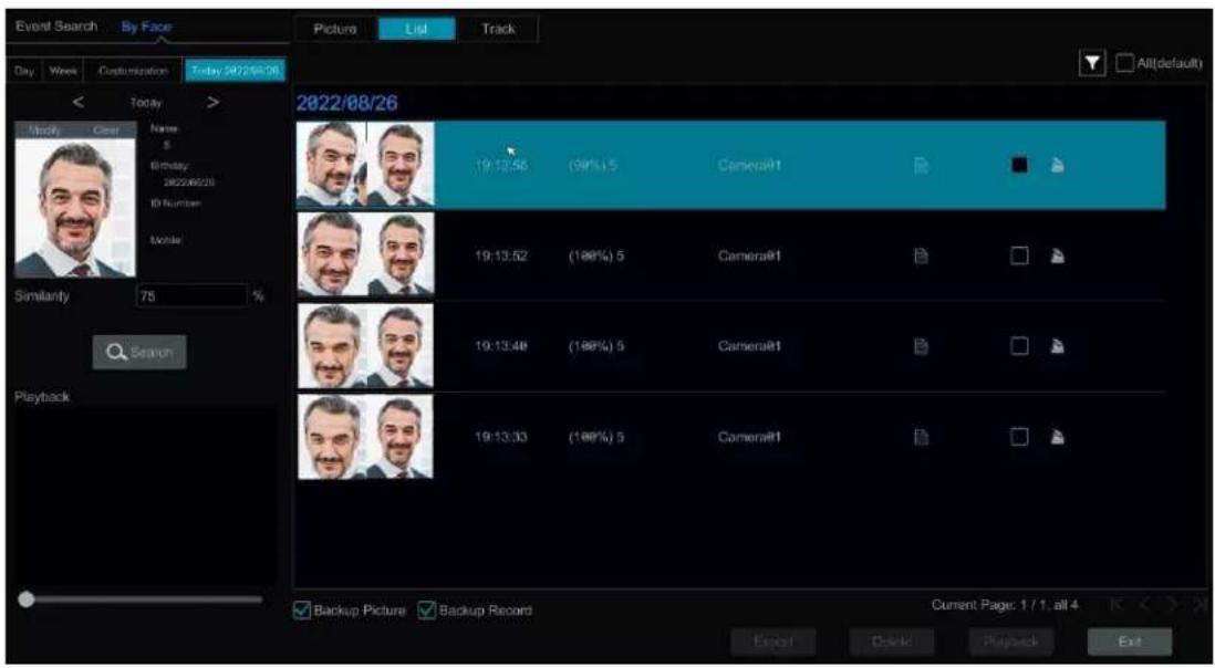
Click the searched image to play a clip. Click 📄 to view the detailed informaon of the comparisons to the target face.
- View Match Images
Click the "Match" tab to view matching images as shown below.

10.2.2 Track Playback
Select "Track" to go to the following interface:

Note: Tracking will only work if two or more cameras have viewed and recorded the subject.
Descripons of buons on the tracking interface
| Fixed Window | Frame | ||||
| Followed Window | Fast Forward (x2;x4) | ||||
| Exchange Window | x1 | Normal Speed | |||
| Stop | Start/Stop Track | ||||
| Play | Edit Map | ||||
| Previous | Edit Color | ||||
| Next | |||||
Click on a camera name for an event list appear to appear. Click one item to play that recording.
Click the buon besides the xed window icon to show "Followed Window" and "Exchange Window" icons. The small playback window will oat on the map window by clicking "Followed Window" as shown below.
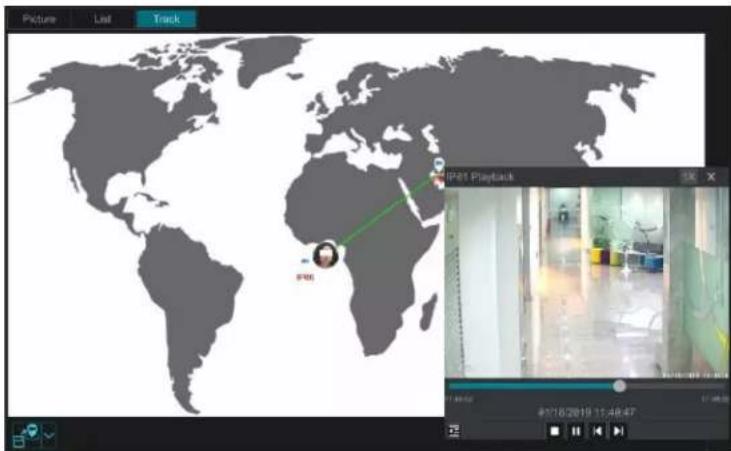
Click 1x to switch play speed. 1x and 2x can be switched. Click 2E to view event list. Click one item to play this event.
Click "Exchange Window" to switch the posion of the map window and the playback window.
Click buon to go to the following interface:

Click "Load Map" to add a map. Drag the camera names onto and around the map to change their locaons. Choose a color from the le color list to set your favorite color for camera names.
Load Map: ① Save the map to a USB storage device and then insert the USB storage device into the NVR. ② Click "Load Map" buon to upload the map.
Click buon to modify the colors of camera names and track lines, and to set the line width.
10.2.3 Face Search by Snapshot
In the live or playback interface, click on a face detector camera and then select 📄 on the toolbar. This will bring up the following window:

Drag the mouse to select a face and then click "Search by Face" to go to the face search by face interface. You can see its snapshot pictures, match pictures, original pictures and so on by clicking the corresponding tab.
10.2.4 Human Body Search (BETA)
Click Start→ Intelligent Analycs→Smart Search→Human Body to go to the human body search interface. Select the search me, camera and event and then click "Search" to view search results.

You can also select the aributes of people to liter (like gender, age, mask-wearing status, glasses-wearing status, color of clothes, etc.). Please note the metadata aribute feature is sll in BETA and results may not be completely accurate.
Click a searched picture to play the recording in the small window on the le. Select pictures and check "Backup Picture" and/or "Backup Record" and then click "Backup" to back up the pictures and /or records. Click "Original" to view the original captured pictures. Click "List" to view the le list of the captured pictures.
Click and select "Add to favorite" to add a favorite group and save the current searched pictures to the favorite group. Then you can quickly view these gure pictures by clicking choosing the group name.

10.2.5 Vehicle Search
① Click Start→ Intelligent Analycs→Smart Search→Vehicle to go to the vehicle search interface.
② Select the me, camera, event and vehicle type. Then click "Search" to search vehicles.
Event: Intrusion, Line Crossing, Target Counng, Plate Detecon, Plate Match-Successful Recognition and Plate Match-Strange Plate can be selected. Aribuon (BETA): Vehicle or non-vehicle aributes can be selected as needed. For example, you can search vehicles according to the color, brand or type. You can view face pictures by me or by camera. Please note the metadata aribute feature is sll in BETA and results may not be completely accurate.
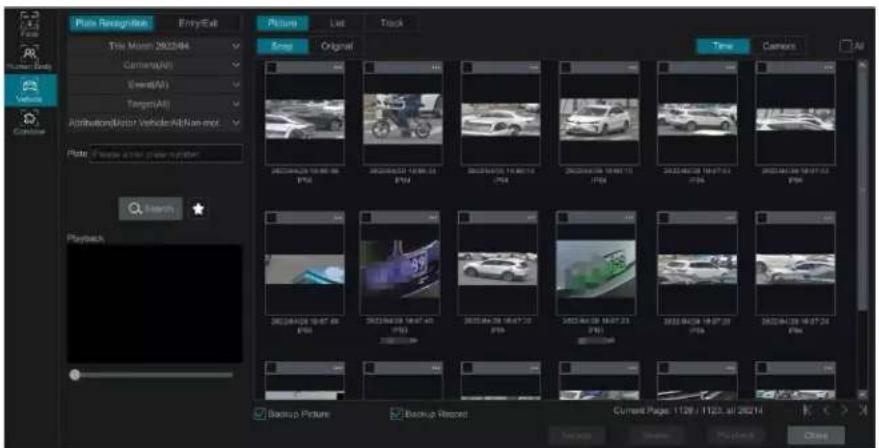
Click a searched vehicle picture to play the clip in the small window on the le. Select vehicle pictures and check "Backup Picture" and/or "Backup Record" and then click "Backup" to back up the pictures and /or records.
③ Click "Original" to see the original pictures; click "List" to view the snapshot informaon list. Click to view the detailed informaon; click to back up the image.
Select "Plate Detecon" or "Plate Match" to view a plate image. You can also enter the plate number to search the plate pictures. Then you can view the track of this vehicle.

Click "Track" to view the track of the vehicle.
Note: Only one plate can be traced at a me and two or more Speco Blue ANPR cameras must have detected this vehicle to create a track to follow. The track setup steps are like the face track setup steps. Please refer to face track sengs for details.
Click ★ to add a favorite group and save the current searched pictures to the favorite group. Then you can quickly view these vehicle pictures by clicking ★ choosing the group name.
10.2.6 Combinaon Search
If you want to view the human body, vehicle or face pictures simultaneously, you can choose to do a combinaon search.
① Click "Combine".
② Select the search me, camera, event and vehicle as needed.
Click a searched picture to play the clip in the small window. Select pictures and check "Backup Picture" and/or "Backup Record" and then click "Backup" to back up the pictures and /or records.
Click ★ to add a favorite group and save the current searched pictures to the favorite group. Then you can quickly view these pictures by clicking
and choosing the group name.
10.3 View Stascal Informaon
Click Start→ Intelligent Analys→ Stascs to go to the interface below. Through this interface, you can view the stascal informaon for people and vehicles, and you can customize the stascal informaon.
*The recorder can display a maximum count of 150,000 analyc data for all meframe views.

bar
| Date | Frequency | |---|---| | 2022-04-14 | 17 | | 2022-05-01 | 36 | | 2022-05-08 | 119 | | 2022-05-15 | 209 | | 2022-05-22 | 361 | | 2022-05-29 | 108 | | 2022-06-05 | 241 | | 2022-06-12 | 257 | | 2022-06-19 | 198 | | 2022-06-26 | 271 | | 2022-07-03 | 361 | | 2022-07-10 | 178 | | 2022-07-17 | 16 | | 2022-07-24 | 8 | | 2022-07-31 | 8 | | 2023-01-07 | 8 | | 2023-01-14 | 8 |View People Informaon:
Note: The person informaon includes face informaon and gure informaon.
① Select the me.
② Select cameras.
③ Select events as needed, such as face detecon, face match, intrusion and tripwire.
Note: Face match events (successful recognition & stranger) are available for some models. If Face Match-Successful Recognition event is selected, you can choose "Detail Chart" to view.
View Vehicle Informaon:
- Click "Vehicle"
- Select the me and cameras.
- Select events as needed.
- Select the vehicle aribuon (BETA).

bar
Intelligent Analytics | Month | Entrance | Exit | |---|---|---| | Jan | 105 | 128 | | Feb | 95 | 76 | | Mar | 84 | 40 | | Apr | 78 | 32 | | May | 72 | 20 | | Jun | 65 | 12 | | Jul | 60 | 18 | | Aug | 357 | 101 | | Sep | 410 | 488 | | Oct | 400 | 500 | | Nov | 360 | 578 | | Dec | 300 | 368 | | Jan-14 | 398 | 428 |If "Remove duplicate license plate numbers" is checked, the duplicate stascs of the same license plate in the same day will not be displayed in the chart.
To customize stascal informaon:
Click "Combine" and then select events, people and vehicle as needed.
10.4 Face Aendance
This funcon is only available for some models. If your device doesn't support face aendance, you can skip these instrucons. Click Start→Intelligent Analycs→Face Aendance to go to the following interface:

To search aendance informaon
① Click ▼ behind camera and group to choose the desired cameras and groups.
② Set the aendance date. You can choose day, week, month and today or customize the me period.
③ Set the workday start me and the end me.
④ Click "Search" to view the attendance status.
If you need to know the aendance status of a specie person, you can click "Advanced" and then enter the name and choose the type. Click "Export" to export the searched aendance informaon.
Click to view the detailed aendance informaon. In this interface, click go to the face search interface.

10.5 Face Check-In
Click Start→Intelligent Analycs→Face Aendance to go to the interface below.
The search steps of face check-in are as follows.
① Click behind camera and group to choose the desired cameras and groups.
② Set the check-in date. You can choose day, week, month and today or customize the me period.
③ Set the face check-in start and end me.
④ Click "Search" to view the check-in status.
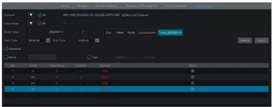
If you want to know the check-in status of a specific person, please click "Advanced" and then enter the name and choose the type to search.
Click to view the detailed informaon. In this interface, the checked image can be viewed.
Click to view the registered face picture of this person.

11 General Event Management
11.1 Sensor Alarm
To ensure complete setup of the Sensor Alarm funcon, you should enable the sensor alarm of each camera and then immediately set up the alarm handling for that camera.
① Click Start→Sengs→Alarm→Sensor to go to the following interface:

② Select the alarm type (NO or NC) according to sensor trigger type.
③ Enable the sensor alarm of each camera and select the schedule.
④ Check the "Duraon", "Record", "Snapshot", "Push", "Alarm-out" and "Preset" and enable or disable the "Buzzer", "Pop-up Video", "Pop-up Message Box" and "E-mail" as required.
⑤ Click "Apply" to save your seings.
The conguraon steps of the above-menoned alarm linkages are as follows.
Duraon: The interval me between adjacent moon detecons. For instance, if the duraon me is set to 10 seconds, once the system detects a moon, it will trigger the alarm alarm and will not detect any other moon (specic to that camera) for 10 seconds. If there is another moon detected during this period, it will be considered as connuous movement.
Record: If checked, the "Trigger Record" window will open automatically (you can also click the "Congure" buon to open the window). Select a camera on the le side and then click 📄 to set the camera as the trigger camera. Select the trigger camera on the right side or click 📄 to cancel the trigger camera. Click "OK" to save your sengs. The trigger camera will record automatically when the sensor alarm is triggered.
Snapshot: If checked, the "Trigger Snapshot" window will open automatically. You can congregate the trigger camera in this window. The trigger camera will capture images automatically when the sensor alarm is acvated.
Push: If checked, choose ON or OFF. If ON, the system will send messages when the sensor alarm is triggered.
Alarm-out: If checked, the "Trigger Alarm-out" window will open automatically. The system will trigger the alarm-out automatically when the sensor alarm is tripped. You need to set the delay me and the schedule of the alarm outputs. See 11.6.1 Alarm-out for details.
Preset: If checked, the "Trigger Preset" window will open automatically. Here you can congregate the trigger preset for each camera. To add presets, please see 6.2 Preset Seng for details.
Buzzer: If enabled, the recorder will emit an audible buzz when the sensor alarm is triggered. To set the delay me of the buzzer, please see 11.6.4 Buzzer for details.
Pop-up Video: Aer camera setup, the corresponding video will pop up automatically when the sensor alarm is triggered. To set the duraon me of the video, please see 11.6.3 Display for details.
Pop-up Message Box: If enabled, the corresponding alarm message box will pop up automatically when the sensor alarm is triggered. To set the duraon me of the message box, please see 11.6.3 Display for details.
E-mail: if enabled, the system will send an e-mail when the sensor alarm is triggered. Before you enable email, please conjure the recipient's e-mail address rst (see 14.1.5 E-mail Conguraon for details).
11.2 Moon Alarm
Moon Alarm: when a moon object appears in the specied area, it will trigger the alarm. You should enable the moon of each camera rst and then set the alarm handling of the camera to complete the whole conguraon of the moon alarm.
11.2.1 Moon Conguraon
① Click Start→Sengs→Camera→Moon Sengs to go to the following interface:

② Select a camera, enable moon, and set the sensitivity and duraon for that camera.
Sensitivity: The higher the value is, the more sensitive it will be to moon. You should adjust the value according to the praccal conditions since the sensitivity is influenced by background color and me (day or night).
Duraon: The interval me between adjacent moon detecons. For instance, if the duraon me is set to 10 seconds, once the system detects a moon, it will trigger the alarm and will not detect any other moon (specific to that camera) for 10 seconds. If there is another moon detected during this period, it will be considered as connuous movement.
③ Drag along the camera image to set the moon area. You can set more than one moon area. Click "All" to set the whole camera image as the moon area. Click "Reverse" to swap the moon area and the non-moon area. Click "Clear" to clear all the moon areas.
④ Click "Apply" to save your sengs. Click "Processing Mode" to go to the alarm handling conguraon interface of the moon alarm.
11.2.2 Moon Alarm Handling Conguraon
① Click Start→Sengs→Alarm→Moon Alarm to go to the following interface:
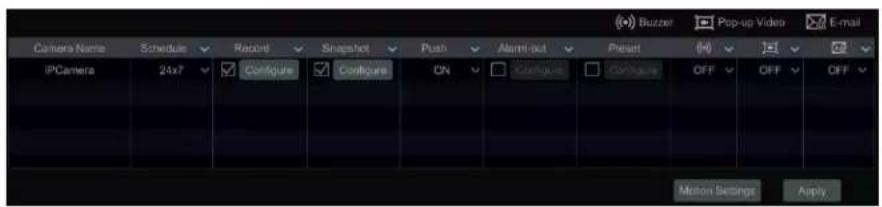
② Enable or disable "Record", "Snapshot", "Push", "Alarm-out", "Preset", "Buzzer", "Pop-up Video" and "E-mail". The alarm handling setup for moon alarm is similar to that of the sensor alarm (see 11.1 Sensor Alarm for details).
③ Click "Apply" to save your sengs. You can click "Moon Sengs" to go to the moon conguraon interface.
11.3 Combinaon Alarm
① Click Start→Sengs→Alarm→Combinaon Alarm to go to the interface below.
② Customize combinaon alarm. Set alarm name and click "Congure" under the Combined Alarm Conguraon menu. Then, select alarm type and alarm source. Finally, click "OK" to save your sengs.
③ Enable or disable "Record", "Snapshot", "Push", "Alarm-out", "Preset", "Buzzer", "Pop-up Video" and "E-mail". The alarm handling setup of combinaon alarm is like that of the sensor alarm (see 11.1 Sensor Alarm for details).
④ Click "Apply" to save your sengs.

11.4 IPC Oine Sengs
① Click Start→Sengs→AI/Event→IPC Oine Sengs to go to the interface as shown below.
② Enable or disable "Snapshot", "Push", "Alarm-out", "Preset", "Buzzer", "Pop-up Video", "Pop-up Message Box" and "E-mail". The IPC Oine setup is similar to that of the sensor alarm (see 11.1 Sensor Alarm for details).
③ Click "Apply" to save your seings.

11.5 Excepon Alarm Sengs
① Click Start→Sengs→AI/Event→Excepon Alarm to go to the interface as shown below.

② Enable or disable "Push", "Alarm-out", "Buzzer", "Pop-up Message Box" and "E-mail". The excepon handling setup is similar to that of the sensor alarm (see 11.1 Sensor Alarm for details).
③ Click "Apply" to save your seings.
11.6 Alarm Event Nocaon
11.6.1 Alarm-out
① Click Start→Sengs→AI/Event→Event Nocaon to go to the following interface:

② Set the delay me and the schedule of each alarm-out. You can click "Edit Schedules" to edit the schedules (see 7.1.2 Schedule Sengs for details).
③ Click "Apply" to save your sengs. You can click "Test" to test the alarm output.
11.6.2 E-mail
Click Start→Sengs→AI/Event→Event Noficaon→E-mail to go to the e-mail conguraon interface. Set the e-mail address of the recipients. See 14.1.5 E-mail Conguraon for details.
11.6.3 Display
Click Start→Sengs→AI/Event→Event Nocaon→Display to go to the display conguraon interface. Set the duraon me of the pop-up video and the pop-up message box. If your device supports two outputs, please set the output of the pop-up video as needed. Aer that, click "Apply" to save your sengs.

11.6.4 Buzzer
Click Start→Sengs→AI/Event→Event Nocaon→Buzzer to go to the buzzer conguraon interface. Set the delay me of the buzzer and then click "Apply" to save your sengs. You can click "Test" to test the buzzer.

11.6.5 Push Message
Click Start→Sengs→ AI/Event →Event Nocaon→Push Message to go to the interface as shown below. Check "Enable" and then click "Apply" to save your sengs. If the Push Server is online, it will push messages to the mobile clients.
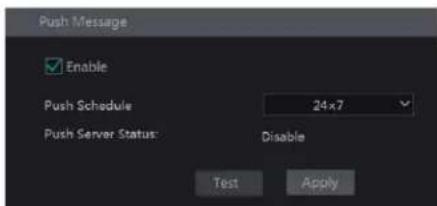
11.6.6 Digital Deterrent
Click Start→Sengs→AI/Event→Event Noticaon→Digital Deterrent to go to the interface as shown below.
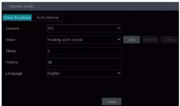
Camera audio sengs:
You can set voice broadcast up for perimeter alert cameras. Select the camera, voice, broadcast mes, volume, and language and then click "Apply" to save your sengs. When an alarm is triggered, the camera will broadcast the voice you set.
Voice: click "Add" to add the alarm voice in WAV format. Click "Listen" to listen to the uploaded audio.
Click "Audio Device" to set the audio of the camera.

Select the camera and then click "Enable" next to audio device.
Audio IN Device: Please select according to the actual device conguraon.
Input Volume: Set the audio input volume as needed.
Speaker (built-in): Please select its funcon as needed.
LOUT (Line Output): Select the funcon of the external audio device as needed.
Audio Out Volume: Set the audio output volume as needed.
Audio IN Encode: Select G711A or G711U
Local Audio Alarm
Set the audio alarm of the local NVR.
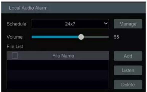
In this interface, you can set the schedule and volume of the local audio alarm. Click "Manage" to set the schedule. Click "Add" to upload the audio le. Choose the uploaded audio le and then click "Listen" to listen to it; click "Delete" to delete this le.
11.6.7 Light
Click Start→Sengs→Alarm→Event Nocaon→Light to go to the interface as shown below. In this interface, you can set the light's ashing me and frequency when an alarm is triggered.

11.6.8 Alarm Server
Go to Alarm→Alarm Server interface as shown below.
Enable the alarm server and enter the server address and port of the alarm server. Next, select the protocol. If "Send Heartbeat" is enabled, set the interval mes. Aer that, test the eecveness of the alarm server. Aer a successful test, please click "Apply". When an alarm occurs, the device will transfer the alarm event to the alarm server. If an alarm server is not needed, there is no need to conjure this secon.
![Alarm Server Enable Server Address Enter Address Port 80 Protocol XML Send Heartbeat Interval Time[s] 10 Schedule 24x7 Manage Alarm Type Configure Motion Alarm Sensor Alarm IPC Offline Object Abandoned/Missing Exception Detection Line Crossing Test Apply](/content/2026/05/1083299/images/d83ee3862be059c6eafffe82d3527199d0f781ea64053187a738ce3380ff6e90.jpg)
11.7 Manual Alarm
Click 📋 on the tool bar at the boom of the live preview interface to open this window. Click "Trigger" to start alarm. Click "Clear" to stop alarm.

11.8 View Alarm Status
Click Start→Sengs→Alarm→Alarm Status or click
In the tool bar at the boom of the live preview interface to view the alarm status.

Click "Clear" to stop the buzzer when a buzzer alarm is triggered. Click ▼ to view the detailed informaon as shown below.

If the excepon informaon is more than one page, you can enter the number in the box and then click / to view the excepon alarm informaon in the previous/next page.
to jump to the specied page. Click
11.9 System Disarming
You can quickly disarm the device through the alarm host or a remote client (such as the mobile app).
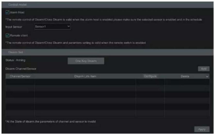
By default, all alarm linkages of all channels and sensor alarms will be disarmed aer clicking "One Key Disarm". You can also self-dene the channels and sensors you want to disarm by clicking "Add". Only the selected channels and sensors will be disarmed by clicking "One Key Disarm".
12 Parking Lot Management
You can manage a parking lot through the NVR. This funcon will only work using compatible Speco Blue ANPR License Plate Cameras.
12.1 Parking Lot Sengs
Click Start→Intelligent Analycs→Parking Lot Management to go to the parking lot setup interface.

12.1.1 Basic Sengs
The recorder only supports the management of one parking lot. Please enter the parking lot name, total parking spaces and remaining parking spaces. To ensure the accuracy of the parking spaces, please enter the parking space informaon while there are no vehicles entering or exing.
12.1.2 Parking Space Sengs
Only the vehicles added into the plate database with the proper permission are allowed to pass through automacally. You can set the parking spaces according to the vehicle groups or directly use the total parking spaces. For the block list, you can set "No parking allowed". Aer that, set the schedule and Email as needed.

12.1.3 Entrance/Exit Management
Set the direcon of vehicles (Enter/Exit) and bind LED screens as needed.

12.2 Parking Lot Management
Aer the above sengs are completed, click "Parking Lot" on the le menu to go to the following interface:
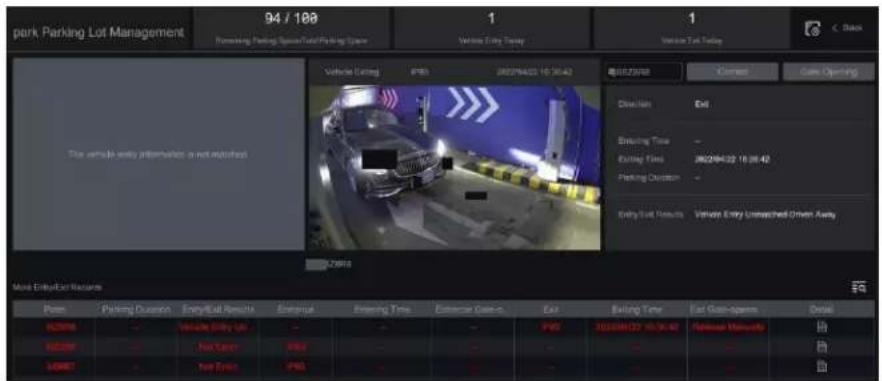
In this interface, you can view the detailed informaon of the parking lot, including the total parking spaces, remaining parking spaces, number of vehicles entering today, number of vehicles exiting today and vehicle entry/exit records.
Only vehicles added into the plate database are allowed to pass automacally. If the vehicle is a stranger/unknown vehicle, it will not be allowed to enter unless it is manually approved. You can release it manually by clicking "Gate Opening". While entering, if the plate number captured is not matched with the actual one, you can click "Correct" to correct it manually.
Click view the detailed informaon of vehicle entry/exing.
Click "More" to register the license plate or view the ID informaon.
Click to the parking lot setup interface.
Click search the records of vehicles entering/exing.
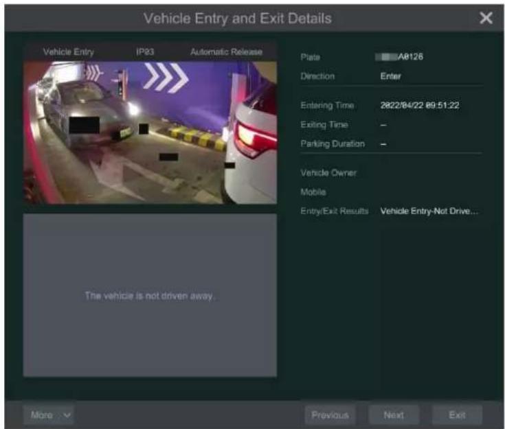
Click "Back" to return to the live view interface.
12.3 Search Vehicle Entry/Exing Records
In the parking lot management interface, click ☑ to search the records of vehicles entering/exing the park lot.
You can search these records by seng Itering condions (including me/direcon/license plate). Click in the right corner of the searched picture to view the details; click "Backup" to export the searched picture.

13 Account & Permission Management
13.1 Account Management
Click Start→Setngs→Account and Authority→Account→Edit User to go to the interface shown below:
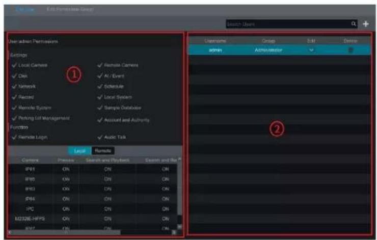
Area ① displays the user permissions. Area ② displays the user list. Click the user in the list to display its user permissions in area ①. There are three default permission groups ("Administrator", "Advanced" and "Common") available when adding accounts. You can manually add new permission group (see 13.3.1 Add Permission Group for details). Only admin and the users that have the "Account and Authority" permission can manage the system's accounts. Group "Administrator" owns all the permissions displayed in area ① except "Account and Authority" and its permissions cannot be changed while the permissions of "Advanced" and "Common" can be changed. For security purposes, only the admin login can add new users.
13.1.1 Add User
① Click Start→Sengs→Account and Authority→Account→Add User or click + beside the search box to open a window as shown below.

② Set the username, password and group. User can also set a paern lock here. The e-mail address is oponal. Click "Add" to add the user.
13.1.2 Edit User
Click Start→Sengs→Account and Authority→Account→Edit User and then click the user list or double click the user to edit the user informaon. Click to delete the user (the admin user cannot be deleted).

Edit Security Queson
You can only set password security for admin. Click "Edit Security Queson" and then set quesons and answers in the popup window. If you forget the password for admin, please refer to Q4 in Appendix A FAQ for details. The passwords of other users can be recovered by admin or the users that have the "Account and Authority" permission.
Modify Password
Only the admin password can be modified. Click "Modify Password" to open a window. Enter the current password and then set new password. Click "OK" to save your sengs.
Modify Paern Lock
Some models may not support this funcon.
Click "Modify Paern Lock" to open this window:

Enter current password and then check "Enable" to input paern lock.

Recover Password
Click "Recover Password" to reset the password to 123456.
Edit User
Click "Edit User" to open the window as shown below. The admin level is enabled, and its permission control is closed and permission group cannot be changed by default. You can enable or disable other users (if disabled, the user will be invalid), open or close their permission control (if closed, the user will get all the permissions which admin has) and set their permission groups. Click "OK" to save your sengs.

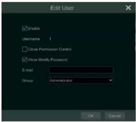
13.2 User Login & Logout
Login: Click Start→Login or directly click the preview interface and then select username and enter the password in the popup window. Click "Login" buon to log in the system.
Logout: Click Start→Logout or click Start→Shutdown to open the "Shutdown" window. Select "Logout" in the window and then click "OK" buon to log out of the system.
13.3 Permission Management
13.3.1 Add Permission Group
Click Start→Sengs→Account and Authority→Account→Edit Permission Group to go to the interface shown below.
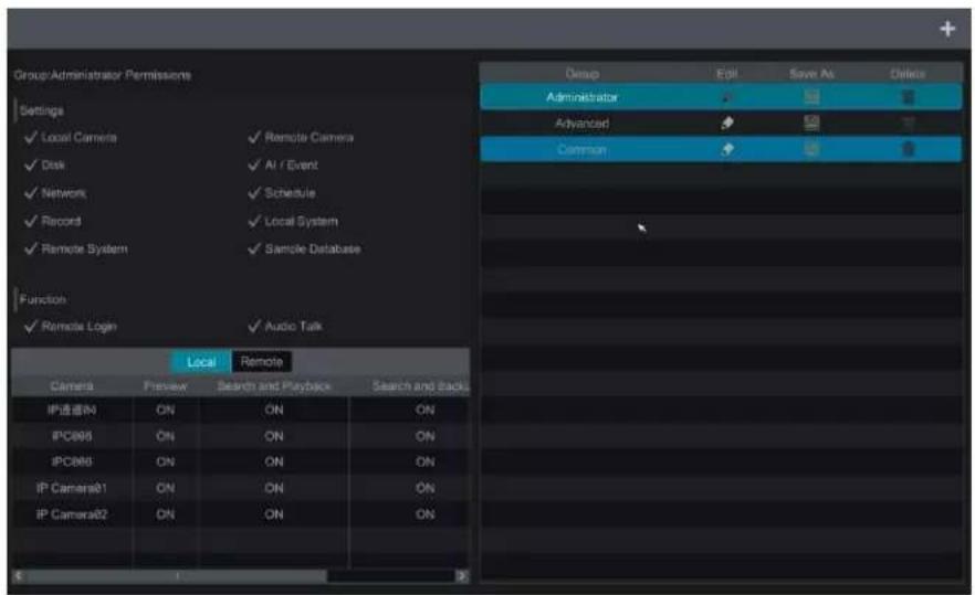
Click ➕ to add permission group. Set the group name, check the permissions as needed and then set the "Local" and "Remote" permissions. Click "Add" to save your sengs.

13.3.2 Edit Permission Group
Go to the "Edit Permission Group" interface and then click in the group list to edit the permission group (the operations of the "Edit Permission Group" are similar to that of the "Add Permission Group", please see 13.3.1 Add Permission Group for details). Click to save the group as a new group. Click to delete the permission group. The three default permission groups ("Administrator", "Advanced" and "Common") cannot be deleted.
13.4 Block and Allow List
① Click Start→Sengs→Account and Authority→Security to go to the following interface:

② Check "Enable" and then choose "Enable Allow List" or "Enable Block List" (a PC client with an IP address in the allow list can access the NVR remotely while a PC client in the block list cannot).
③ Add IP/IP segment/MAC. Click "Add IP" or "Add MAC" buon and then check "Enable" in the popup window (it must be checked for the IP/IP segment/MAC you add be eecve). Enter the IP/IP segment/MAC and then click "OK" buon. In the above interface, click edit IP/IP segment/MAC, click to delete it. Click "Apply" to save your sengs.
13.5 Preview On Logout
Click Start→Seings→Account and Authority→Security→Preview On Logout to go to the interface below.
Set a camera and then enable or disable the preview permission on logout as required. If a camera's preview permission on logout is "ON", you can view the live image of the camera when you are logged out of the system. Otherwise, the live image of the camera cannot be seen when logged out.

13.6 Network Security
Click Start→Sengs→Account and Authority→Security→Network Security to go to the interface below.

ARP (Address Resoluon Protocol) Guard: This funcon can protect the LAN from ARP aacks and increase the network stability. If it is enabled, you can enable auto gateway MAC or manually set gateway MAC. Additionally, detecon defense also can be enabled as needed.
13.7 Password Security
Click Start→Sengs→Account and Authority→Security→Password Security to go to the following interface:
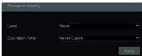
In this interface, you can set the security level and expiraon me of the password. enhance system security.
It's recommended to force a new password periodically to
13.8 View Online User
Click Start→Sengs→Account and Authority→User Status to view the online user informaon (you can view username, login type, IP address and login me for all acve users online; click open a window showing the preview occupied channel number and playback occupied channel number).
14 Device Management
14.1 Network Conguraon
14.1.1 TCP/IP Conguraon
Click Start→Sengs→Network→TCP/IP to go to the interface below. Check "Obtain an IPv4 address automacally", "Obtain an IPv6 address automacally" and "Obtain DNS automacally" to get the network addresses automacally, or manually enter the network addresses. You can modify the MTU value according to the network condition (MTU, Maximum Transmission Unit, can be modified according to network condition for higher network transmission eciency). Click "Apply" to save your sengs.
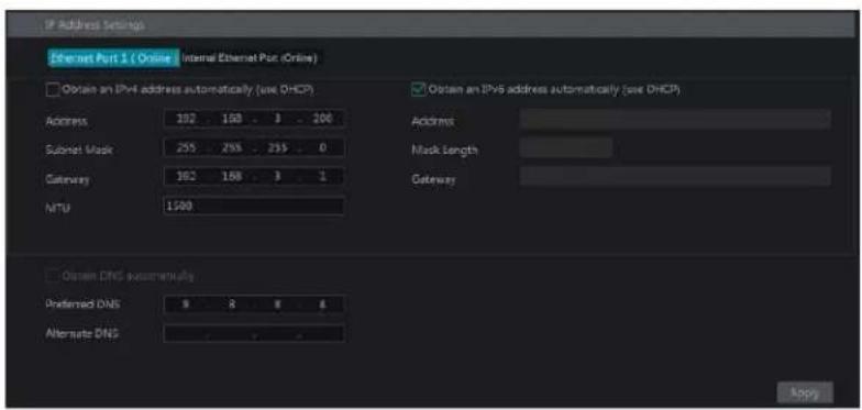
Note:
- Internal Ethernet Port
If you use an NVR with PoE network ports, click "Internal Ethernet Port" to go to the interface below.
The internal Ethernet port is the port which connects all PoE ports with the NVR system. The PoE ports are available if the internal Ethernet port is online; if it is oine, all the PoE ports will be unavailable and it's possible there's an issue with the Ethernet port. The network address of the internal Ethernet port can be changed to be in the same network segment as IP cameras which are directly connected to the PoE ports of the NVR (Note that it is not recommended to change the network address of the internal Ethernet port).
Mode: Non-long line mode or long line mode can be selectable. The non-line mode is the default seng. If you want to run your PoE cameras longer than the standard 100M distance, you can choose long line mode. The tradeo will be that your network speed on all PoE ports will drop to 10MBPs.

14.1.2 Port Conguraon
Click Start→Sengs→Network→Port to go to the interface shown below. Enter the HTTP port, HTTPS port, server port and RTSP port of the NVR, enable "Anonymous" as needed and then click "Apply" buon to save your sengs.
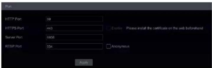
HTTP Port: the default HTTP port of the NVR is 80. For security, the port number can be changed another number such as 81. The port is mainly used for web client access. If you want to access the NVR through a web browser, you should enter the IP address plus HTTP port in the address bar of the web browser like hp://192.168.11.61:81.
Note: The HTTP port and server port of the NVR should be mapped to the router before you access the NVR via WAN.
HTTPS Port: the default HTTPS port of the NVR is 443.
HTTPS provides authencaon of the web site and protects user privacy. You can enter IP address plus HTTP port in the address bar of the web browser. Then enter username and password to log in. Click Settings→Network→HTTPS to go to the interface below. There are three ways to enable HTTPS service.
① Select "Create a private cercate".
② Click "Create".
③ Fill out the corresponding informaon in the above creaon box. Enter the country (two leer code), domain (NVR's IP address/domain), validity date, password, province/state, region and so on.
④ Click "OK".
⑤ Check "Enable" checkbox.
⑥ Click "Apply" to save your settings.
B. Install a signed cercate

① Check "Signed cercate already....".
② Click "Browse" to select the cercate you want to import.
③ Click "Import".
④ Check "Enable".
⑤ Click "Apply" to save your seings.
Please note that the cercate uploaded here must be a cercate with private key.
To each a private key to the cercate, please open the cercate and the private key les with an editor (such as Notepad++) and then copy the private key to the cercate.
C. Create a cercate request

① Check "Create a cercate request".
② Click "Create".
③ Fill out the corresponding informaon in the above creaon box. Enter the country (two leer code), domain (NVR's IP address/domain), validity date, password, province/state, region and so on.
④ Click "OK". Then a cercate request le (CSR) will be created.
⑤ Click "Export" to export the cercate request le. Then send this le to the trusted third-party CA to apply a signed certificate.
⑥ Click "Browse" and select the signed cercate issued by the CA and then import this cercate.
⑦ Click "Enable".
⑧ Click "Apply" to save your settings.
Aer that, the device can be accessed by entering hps://{IP-address}: {hps port} via the web browser (e.g. hps://192.168.1.201:443).
Server Port: the default server port of the NVR is 6036. The server port number can be changed as required. The port is mainly used in network video system management.
POS Port: the default POS port of the NVR is 9036.
API Server: You can log into a media player which supports the RTSP protocol. Moreover, a third-party can further develop performance through an API service.
Authencaon: Basic authencaon and digest authencaon are oponal.
RTSP Port: RTSP real-me stream protocol can be used to control the transfer of real-me data. Through a media player which supports the RTSP real-me stream protocol (Such as VLC player), you can view live images synchronously. The default RTSP port is 554 and it can be changed as needed. (The address format: rtsp://IP address:554/chID=1&streamType=main or rtsp://IP address:554/chID=1&streamType=sub; main indicators main stream; sub indicators sub stream; chID indicators channel ID).
Examples: Enable RTSP and "Anonymous". Then open VLC player and enter the address (for example:
rtsp://192.168.1.88:554/chID=1&streamType=main) in the network address bar of VLC player. You can then view the video of channel 1.
14.1.3 PPPoE Conguraon
Click Start→Sengs→Network→PPPoE to go to the interface as shown below. Check "Enable" in "PPPoE Sengs" and then enter the username and password obtained from the dealer. Click "Apply" to save your sengs.

14.1.4 DDNS Conguraon
The DDNS is used to control the dynamic IP address through a domain name. Speco Technologies provides free DDNS service with US-based servers. You can access the NVR easily if the DDNS is enabled and congured. Click Start→Sengs→Network→DDNS to go to the interface shown below. The default DDNS type will be "specoddns.net". A default domain name will be provided, and you can use this for your domain name or enter your own. If your
selected DDNS name is invalid or taken, please select another domain name. Click on test to conrm if the DDNS Domain is OK. If so, you may now go to [your domain name].specoddns.net with a browser and access your recorder remotely.
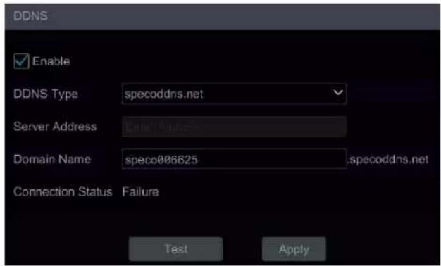
14.1.5 E-mail Conguraon
Click Start→Sengs→Network→E-mail to go to the interface below. Enter the sender's name, e-mail address, SMTP server and SMTP port (you can click "Default" to reset the SMTP port to the default value) and then enable or disable the SSL and aaching image.
Aaching Image: Choose "NO", "A Picture" or "Mulple Pictures". If "A Picture" or "Mulple Pictures" is selected, snapshot image or original image can be selected to each.
Select the username (the username list will be updated automatically according to the email address you input) and enter the password of the sender and then click "Apply" to save your sengs (you don't have to enter the username and password if "Anonymous Login" is enabled). Click "Test" to open a window. Enter the e-mail address of the recipient in the window and then click "OK." The e-mail address of the sender will send an e-mail to the recipient. If the e-mail is sent successfully, it indicates that the e-mail address of the sender is congured correctly.

Click "Edit Recipient" to go to the following interface:

Click "Add" and then enter the recipient's e-mail address and select the schedule (if a schedule is selected, the system will send the alarm email and the recipient will receive it only in the selected schedule me) in the popup window. Click "Add" in the window to add the recipient. You can also change the recipient's receiving schedule by clicking √ in the "Schedule" column. Click 🔒 to delete the recipient in the list. Click "Apply" to save your sengs. Click "Edit Sender" to go to the e-mail conguraon interface of the sender.
14.1.6 UPnP Conguraon
By UPnP you can access the NVR through the web client which on the WAN via a router without port mapping.
① Click Start→Sengs→Network→UPnP to go to the interface below.
② Make sure the router supports UPnP funcon and the UPnP is enabled in the router.
③ Set the NVR's IP address, subnet mask and gateway and so on corresponding to the router.
④ Check "Enable" in the interface as shown below and then click "Apply" button.
Click "Refresh" buon to refresh the UPnP status. If the UPnP status is sill "Invalid UPnP" aer refreshing, the port number is wrong. Please change the mapping type to "Manual" and then click 📋 to modify the port until the UPnP status turns to "Valid UPnP". Refer to the picture below. You can view the external IP address of the NVR. Enter the external IP address plus port in the address bar of your browser to access the NVR (example: hp://183.17.254.19:81).

14.1.7 802.1X
If 801.1X is enabled, NVR data can be protected. When the NVR is connected to the network protected by IEEE 802.1X, user authencaon is needed.

To use this funcon, the NVR must be connected to a switch supporting the 802.1x protocol. The switch can be considered as an authencaon system to identify the device in a local network. If the NVR connected to the network interface of the switch has passed the authencaon of the switch, it can be accessed via the local network.
Protocol type and EAPOL version: Please use the default sengs.
Username and password: The username and password must be the same as the username and password applied for and registered in the authencaon server.
14.1.8 NAT Conguraon
Click Start→Sengs→Network→NAT to go to the interface for NAT conguraon and check "Enable". Click "Apply" to save your sengs and make note of the QR code number under the QR code. Via a browser, go to connect.specotech.cloud, input the QR code number, your username and password to login. Note that you will need to install a plugin through the browser to get this feature to work.

Check "Enable" and then select the NAT server address. Click "Apply" to save your sengs.
You can scan the QR Code on the Speco Blue app installed on a mobile phone or tablet PC to quickly add the device to the server list of the mobile app.
Access Type: NAT or NAT2.0 can be selected.
Click "Advanced" to select the area as needed.
Note:
- If you want to use the cloud upgrade, Speco Blue app, P2P web access or advanced browser features, you must enable NAT2.0.
- Aer the NAT is enabled, use the Speco Blue app to scan the QR code. The device will be added to the server list of the Speco Blue app.
- The device can be added to the account of the Speco Blue app only when NAT2.0 is enabled. Aer NAT2.0 is enabled, when you add the device to the account of the Speco Blue app, you must enter the security code of the device here.
Aer the device is bound to the account of the mobile app, the blue binding informaon will be shown under the QR code. Click this blue informaon to unbind it.
14.1.9 Cloud Upgrade
Note: Before you use cloud upgrade, please enable NAT2.0.
① Click Start→Sengs→Network→Cloud Upgrade as shown below.

② Select "Accept Nocaon Only" or click "Check for Updates" to check whether the current version is the latest. If your soware version is not the latest, click "Upgrade" to download and upgrade from the cloud server.
③ Please don't power o during the upgrade process.
④ Only users with Network user authority can acvate and use this feature. If the dealer does not wish to provide this capability to their users, they can ensure that only the main Admin login has network authority.
14.1.10 Plaorm Access
Some models may not support this funcon.
This funcon is mainly used for connecng from the Speco Blue VMS. The setup steps are as
follows: Click Start→Sengs→Network→Integraon→Plaorm Access to go to the
interface.

Plaorm Access
① Set "Access Type" as "Plaorm Soware" and select "Enable" as shown below.
② Check the IP address and port of the transfer media server in the Speco Blue VMS. The default server port for auto report is 2009. If it is modified, please go to the transfer media interface to verify.
③ Enable the auto report in the Speco Blue VMS when adding a new device. Then self-dene a device ID and complete the remaining information of the device in the Speco Blue VMS.
④ Enter the above-menoned server address, port and report ID in the server interface. Then click "Apply" to save your sengs. Now Speco Blue VMS will automatically connect this device.
14.1.11 UPnP Report Access
In this interface, you can also access a third-party plaorm by UPnP Report. Click Start→Sengs→Network→Integraon→UPnP Report. If this one is enabled, please enter the server address, port and manufacturer ID.

14.1.12 ONVIF
The device supports ONVIF (Prole G/T/S) and the model name can be searched on the ONVIF social website. Aer ONVIF is enabled, it can be searched and connected to a third-party plaorm via ONVIF protocol.
Click Start→Sengs→Network→Integration→ONVIF to enter the following interface:
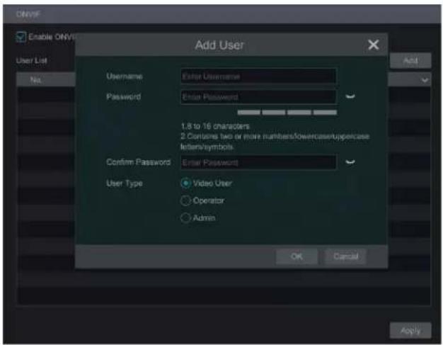
Note: when adding the device to a third-party plaorm with ONVIF protocol, please check "Enable ONVIF" rst and then enter the username and password created in the above interface.
14.1.13 Network Status
Click Start→Sengs→Network→Network Status to view the network status to view network status conveniently.
Click Start→Sengs→Network→Network Status Detecon. Enter the IP address and then click "Test" to check the network conncon status (like network delay, packet loss).
14.2 Basic Conguraon
14.2.1 General Conguraon
Click Start→Sengs→System→Basic→General Sengs to go to the interface below. Set the device name, device No., language, video format and main output. Enable or disable wizard, "Log In Automatically", "Log Out Automacally" (if checked, you can set the wait me), "App Live Self-Adapon" and "Dwell Automacally" (if checked, you can set the wait me). Click "Apply" to save your sengs.
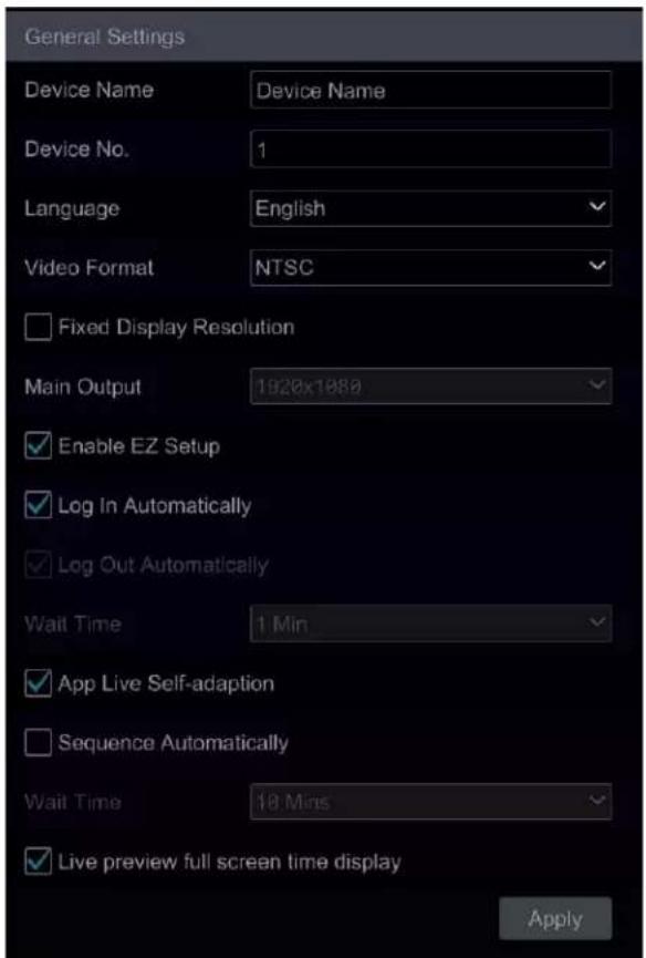
Device Name: The name of the device. It may display on the client end or CMS to help users recognize the device remotely.
Video Format: Two modes: PAL and NTSC. Select the video format according to the camera.
Main Output: Enable "Fixed display resolution" and then select the main output as needed.
Note: You can set the resolutions of the main output and secondary output respectively if the NVR has dual outputs. Refer to the picture shown below.
Sequence Automacally: Select and set "wait me". The system will sequence automacally if it is not operated during the me you set.
14.2.2 Date and Time Conguraon
Click Start→Sengs→System→Basic→Date and Time to go to the interface shown below.
Set the system me, date format, me format and me zone of the NVR. The default me zone is GMT-05 New York, Toronto, Washington. If the selected me zone includes DST, the DST of the me zone will be checked by default. Click "Apply" to save your sengs.
You can manually set the system me or synchronize system me with network through NTP.
Manual: select "Manual" in the "Synchronous" opon and then click aer the "System Time" opon to set the system me.
NTP: select "NTP" in the "Synchronous" opon and then enter the NTP server.

14.2.3 Recorder OSD Sengs
Click Start→Sengs→System→Basic→Recorder OSD sengs to go to the interface below. OSD name and icon can be enabled here.

14.2.4 PoE Sengs
- PoE Management
Click Start→Sengs→System→Basic Sengs→PoE Power Management to go to the interface below. This funcon is only available for recorders with built-in PoE.
![PoE Power Management PoE Plug-and-Play Settings PoE Port Enable ✓ Current Power PoE[01] ON ✓ 0.00W PoE[02] ON ✓ 0.00W PoE[03] ON ✓ 0.00W PoE[04] ON ✓ 0.00W PoE[05] ON ✓ 0.00W PoE[06] ON ✓ 0.00W PoE[07] ON ✓ 0.00W PoE[08] ON ✓ 0.00W PoE[09] ON ✓ 0.00W PoE[10] ON ✓ 0.00W PoE[11] ON ✓ 0.00W PoE[12] ON ✓ 0.00W PoE[13] ON ✓ 0.00W PoE[14] ON ✓ 0.00W PoE[15] ON ✓ 0.00W PoE[16] ON ✓ 0.00W Total Power: 150.00W, Remain Power: 150.00W Apply](/content/2026/05/1083299/images/79c0d99a91224ccf8eb8fd5a825e33c7001b2d2d5d23c180b118554f75c327db.jpg)
In this interface, you can view the current power consumption of any aached POE cameras. The PoE power supply of the PoE camera/panel can be enabled or disabled by selecng "ON" or "OFF" as needed. This can also be done remotely through the Web browser.
● PoE Plug-and-Play Sengs
![PoE Power Management PoE Plug-and-Play Settings Enable PnP PoE Port ✓ PoE[01] ✓ PoE[02] ✓ PoE[03] ✓ PoE[04] ✓ PoE[05] ✓ PoE[06] ✓ PoE[07] ✓ PoE[08] ✓ PoE[09] ✓ PoE[10] ✓ PoE[11] ✓ PoE[12] ✓ PoE[13] ✓ PoE[14] ✓ PoE[15] ✓ PoE[16] *After the PoE port is unchecked, Plug-and-Play is not supported, and channels can be added manually Apply](/content/2026/05/1083299/images/5845aa59903cc5818a840c080df2925c72d9be79ab5b169dc310db6e11447ce6.jpg)
The PnP funcon of each PoE port is enabled by default. You can directly connect a PoE IPC to the PoE port of the NVR with a network cable.
You can also connect a PoE IPC to the NVR via a PoE switch by the following steps:
-
Disable the PnP funcon of a PoE Port through the interface shown above.
-
Connect the PoE switch to a PoE port of the NVR with a network cable.
-
Connect the PoE IPCs to the PoE switch with network cables.
-
Go to Start→Sengs→Network→Internal Ethernet Port interface. Set the IP address segment and mode as needed.
-
Go to Start→Setngs→Camera→Edit Camera interface. Click "Add Camera" to add these PoE IPCs manually.
Note: If the above-menoned PoE IPCs are added to the NVR successfully, the corresponding number of PoE ports will be occupied. For example, if the NVR has 16 PoE ports and one of them is used to connect a PoE switch with 8 connected PoE IPCs, then only 8 PoE ports of the NVR remain to directly connect PoE cameras. You cannot exceed the total channel count of a recorder.
14.3 Factory Default
Click Start→Sengs→System→Maintenance→Factory Default and then click the "Reset to factory default" buon in the interface to reset your unit to the factory default sengs (check "Reset retain Network Conguraon" to retain the network sengs).
Note: Restoring the factory default sengs will not change the me zone.
14.4 Device Soware Upgrade
- Upgrade
You can click Start→Sengs→System→Informaon→Basic to view MCU, kernel version, rmware version and so on.
Upgrade steps are as follows:
① Copy the upgrade soware onto a USB storage device.
② Insert the USB storage device into a USB interface of your NVR.
③ Click Start→Sengs→System→Maintenance→Upgrade to go to "Upgrade" interface. Select the USB device in "Device Name" opon and go to the path where the upgrade soware resides. Select the upgrade soware and then click "Upgrade". The system may automatically restart during upgrading. Please wait for the upgrade to nish and it's critical to not power o the NVR during the upgrade process.
Note: The file system format of your USB mobile device used for upgrade, back up and restoration should be FAT32.
14.5 Backup and Restore
You can back up the conguraon le of the NVR and export the le to other storage devices; in this way, you can implement the conguraon to other NVRs of the same model and save setup me.
Insert the USB storage device into a USB interface on the NVR and then click Start→Sengs→System→Maintenance→Backup and Restore to go to the interface.
- Backup
Select the USB device in "Device Name" opon; go to the path where you want to store the conguraon backup le and then click "Backup" buon; nally, click "OK" in the popup window.
- Recover
Select the USB device in "Device Name" opon; nd the conguraon backup le and then click "Recover" buon; nally, click "OK" in the popup window.
14.6 Restart Automacally
You can set an automac restart time for your NVR to maximize performance. Click Start→Sengs→System→Maintenance→Auto Maintenance to go to the interface as shown below. Enable auto maintenance, set the interval days and point of me and then click "Apply" to save your sengs. The NVR will restart automatically at the appointed me every *interval* days.

14.7 View Log
Click Start→Sengs→System→Maintenance→View Log to go to the log view interface. Select the log type, click me and then click the "Search" buon. The log le search results will be displayed in the list.
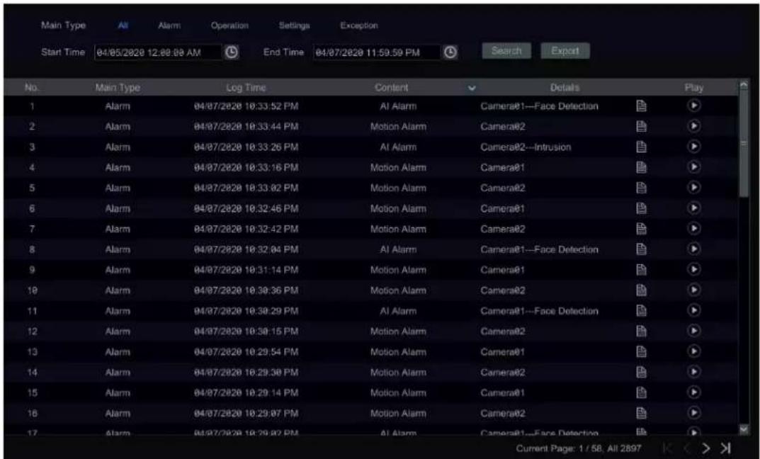
Choose the log le in the list and then click "Export" buon to export the log le. Click on the "Content" tle bar to open a menu list. Using the check box, check contents on the menu list and then the log list will show only the checked log contents. Click to play the video log.
14.8 View System Informaon
Click Start→Sengs→System→Informaon and then click the corresponding menu to view the "Basic", "Camera Status", "Alarm Status", "Record Status", "Network Status" and "Disk" informaon of the system.
15 Remote Surveillance
15.1 Speco Blue app
① Enable NAT in the NVR. Refer to 14.1.8 NAT Conguraon for details.
② Scan the QR Code through the Speco Blue App available for iOS and Android to easily and securely view your cameras.
③ Run the Speco Blue app, go to the "Add Device" interface and then click □ to scan the QR Code of the NVR (Go to Start→Sengs→System→Informaon→Basic to view the QR Code of the NVR).
④ Aer scanning the QR Code successfully, enter the password to log into your mobile client.

15.2 Web LAN Access
① Click Start→Seings→Network→TCP/IP to go to the "TCP/IP" interface. Set the IP address, subnet mask, gateway, preferred DNS and alternate DNS of the NVR.
② Open the Web browser on your computer, enter the IP address of the NVR in the address bar and then press enter to go to the login interface shown below. You can change the display language on the top right corner of the login interface. Enter the username and password of the NVR in the interface and then click "Login" to go to the live view interface.

Notes: 1. Please make sure that the IP address of the NVR and the computer are both in the same local network segment. For example, if the IP address of the computer is 192.168.1.41, the IP address of the NVR should be set to 192.168.1.XXX. 2. If the HTTP port of your NVR is not 80 but another number, you need to input the IP address plus port number in the IE address bar when accessing the NVR over a network. For example, if the HTTP port is 81, you should enter http://192.168.1.42:81 in the address bar.
15.3 Web WAN Access
① Set the network of the NVR. Please refer to 14.1.1 TCP/IP Conguraon for details.
② Click Start→Sengs→Network→NAT to go to the interface for NAT conguraon and check "Enable". Click "Apply" to save your sengs and make note of the QR code number under the QR code. Via Internet Explorer, go to connect.specotech.cloud, input the QR code number, your username and password to login.

> PPPoE Access
① Click Start→Sengs→Network→PPPoE to go to the "PPPoE" interface. Check "Enable" in the "PPPoE sengs" and then enter the username and password provided by your ISP. Click "Apply" to save your sengs.
② Click Start→Sengs→Network→Network Status to view the IP address of the NVR.
③ Open the web browser on your computer, enter the IP address of the NVR like hp://210.21.229.138 in the address bar and then press enter to go to the login interface. Enter the username and password of the NVR in the interface and then click "Login" to go to the live view interface.
Router Access
① Click Start→Sengs→Network→TCP/IP to go to the "TCP/IP" interface. Set the IP address, subnet mask, gateway, preferred DNS and alternate DNS of the NVR.
② Set the HTTP port (it is suggested to modify the HTTP port because the default HTTP port 80 might be taken up) and enable UPnP funcon in both the NVR and the router. If the UPnP funcon is not available in the router, you need to forward the LAN IP address, HTTP port and server port of the NVR to the router. Port mapping sengs may be dierent in dierent routers, so please refer to the user manual of the router for details.
③ Get the WAN IP address of the NVR from the router. Open the web browser on your computer, enter the WAN IP address plus HTTP port like hp://116.30.18.215:100 in the address bar and then press enter to go to the login interface. Enter the username and password of the NVR in the interface and then click "Login" to go to the live view interface.
Note: If the WAN IP address is a dynamic IP address, it is necessary for you to use the domain name to access the NVR. Click Start→Settings→Network→DDNS to set DDNS (see 12.1.4 DDNS Configuration for details). By using the DDNS function, you can use the domain name plus HTTP port like http://sunshine.dvrdydns.com:100 to access the NVR via the Internet.
15.4 Web Remote Control
Your NVR supports Web client access with or without plug-in. The plug-in for HTLM5 browsers oers much improved features and performance. The supported browsers (green color) for remote access with a plug-in are as follows. The red color versions are not supported.
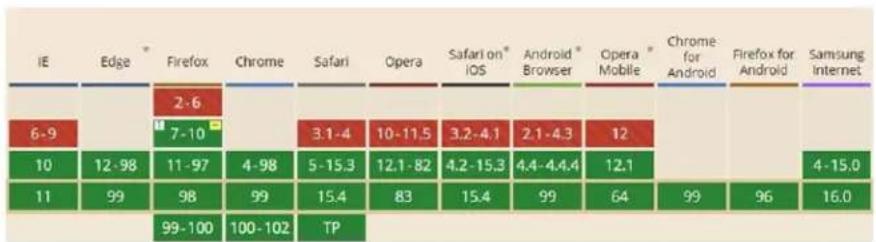
other
| IE | Edge | Firefox | Chrome | Safari | Opera | Safari on* iOS | Android * Browser | Opera Mobile | Chrome for Android | Firefox for Android | Samsung Internet | |---|---|---|---|---|---|---|---|---|---|---|---| | 6-9 | 12-98 | 7-10 | 2-6 | 3:1-4 | 10-11.5 | 3.2-4.1 | 2.1-4.3 | 12 | 10 | 12-98 | 11-97 | | 10 | 99 | 98 | 99 | 5-15.3 | 12.1-82 | 4.2-15.3 | 4.4-4.4.4 | 12.1 | 11 | 12-98 | 11-97 | | 11 | 99 | 98 | 99 | 15.4 | 83 | 15.4 | 99 | 64 | 99 | 96 | 100-102 | TPWhen you access the NVR through the above web browser for the rst me, the browsers need to download and install the relave components for normal preview and playback.
If your browser asks for permission on the conguraon modicaons aer the plug-in runs, please allow it or the interface will not display normally; if the relevant ports of the plug-in (port 11563; port 12863; port 13863) are occupied, the system will tell you which program currently occupies the port. Please stop the occupying program.
The supported browsers (green color) for remote access without the plug-in are as follows. The red color versions are not supported.
The buons and icons on the top right corner of the remote interface are introduced as follows.
admin: the current login username.
Logout: click to log out and return to the login interface.
Modify Password: click to change the password of the currently acve user. Enter the current password and then set a new password in the popup window. Click "OK" to save the new password.
Local Sengs: click to change the local sengs. Set the snapshot number and click "Browse" to set the snapshot path and record path as shown below. Click "Apply" to save your sengs.

Below as an introducon is a web browser with the applicable plug-in installed.
15.4.1 Remote Preview
Click "Live View" in the remote interface to go to the live view interface. The live view interface consists of the four areas marked in the following picture:

Start Preview
Select a window in the preview area and then click one online camera on the le panel to preview the camera in the window. You can click the tool bar to preview all the cameras.

▶ Left Panel Introducon
Click < on the le panel to hide the panel and click > to show the panel. You can view all the added cameras and groups on the le panel.
- View Camera
Click to view the cameras. You can view the number of all the added cameras and the online cameras. For instance, the le number 3 in
Camera (3/3)
on the le panel stands for the number of online cameras; the right number 3 stands for the number of all the added cameras.
Enter the camera name in the search box and then click 🔒 to search for the camera. Click 🔒 to refresh the camera list.
• View Group

to view the groups. The top side of the le panel displays all the groups and the boom displays all the cameras in the group.
- View Scheme

to view the scheme. All schemes can be shown in the le panel. Double click the scheme name to quickly invoke it.
Tool Bar Introduction
| Buon | Meaning | ||
| [HACK] | Screen mode buon. | ||
 | Click to disable OSD. Click to enable OSD. | ||
 | Click to show full screen. Right click on the full screen to exit full screen. | ||
 | Sub Stream | Click “All Main Stream” or “All Sub Stream” to set the stream of all the cameras at once. | |
 | Manual alarm buon. Click to open a window and then trigger and clear the alarm-out in the window manually. | ||
 | Click to preview all cameras. | ||
| [COC7] | Click to close all the preview cameras. | ||
| [OGDX] | Click to start recording all cameras to the local computer. Click again to stop recording. | ||
 | Click to start manual record of all cameras to the NVR. Click again to stop manual record for all cameras. | ||
 | Click to enable talk through the NVR. | ||
Right Panel Introducon
Click on the right panel to show the panel and click to hide the panel.

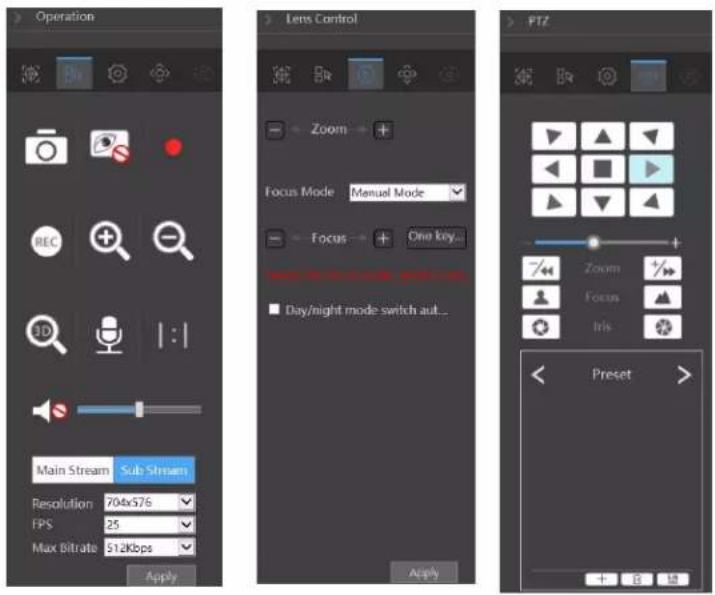
Click one camera window in the preview area and then click Main Stream to set the camera's live view stream and record stream to main stream in manual record mode; click Sub-stream to set the camera's live view stream and record stream to sub stream. In sub stream tab, set the resolution, FPS and bitrate and then click "Apply" to save your sengs.
Operaon panel introducon:
| Buon | Meaning |
| Click to take snapshots. | |
| Click to start recording to computer; click it again to stop recording. | |
| Click to zoom in on the image of the camera and then drag the mouse on the camera image to view the hidden area. | |
| Click to zoom out of the image of the camera. | |
| The 3D zoom in funcon is designed for P.T.Z. Click the buon and then drag the image to zoom in or zoom out the image; click the image on dierent areas to view the image of the dome omni-directionally. | |
| Click to start recording to the NVR | |
| Click to close the preview camera. | |
| Click to enable audio and then drag the slider bar to adjust the volume. You can listen to the camera audio by enabling audio. |
PTZ panel introducon:
| Buon | Meaning |
 | Click ▲ / ▼ / ▼ / ▼ / ▲ / ▲ / ▲ to rotate the dome; click to stop rotang the dome. |
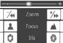 | Drag the slider to adjust the rotang speed of dome. |
| Click /to room in/out camera image. | |
| Click ▲ / ▲ to increase/ decrease the focal length. | |
| Click / to increase/decrease the iris of the dome. | |
| Preset | Click to view the preset list and then click the buon in the list to call the preset. Click + to add a preset; click to save the preset sengs; click to delete the selected preset |
| Cruise | Click to view the cruise list. Click to add a cruise; click to play the cruise; click to stop cruise. |
| Cruise Group | Click to view the cruise group list. Click to add a cruise group; click to play the cruise group; click to stop cruise group. |
| Trace | Click to view the trace list. Clicktoadd a trace; click toplay the trace clicktostart record. |
15.4.2 Remote Playback
Click "Playback" in the remote interface to go to the playback interface.
① Check the record event types and cameras on the le panel. Set the record date on the calendar beside the me scale.
② Click 🔒 to search the record data and then click 🔒 or directly click the me scale to play the record.
The operaon of the playback me scale is like that of the me scale in the main program of the NVR. Please refer to 8.2 Playback Interface Introducon for details.
Introducon of playback control buons:
| Buon | Meaning |
| [CST6] | Stop buon. |
| Rewind buon. Click to play video backwards. | |
| Play buon. Click to play video forwards. | |
| Pause buon. | |
| Deceleraon buon. Click to decrease the playing speed. | |
| Acceleraon buon. Click to increase the playing speed. | |
| Previous frame buon. It works only when forward playing is paused in single screen mode. | |
| Next frame buon. It works only when forward playing is paused in single screen mode. | |
 | Click to step backward 30s and click to step forward 30s. |
 | Backup start me buon. Click the time scale and then click to set the backup start time. |
| Backup end me buon. Click the me scale and then click to set the backup end me. | |
| Export buon. | |
| Backup tasks buon. Click to view the backup status. | |
| Event list buon. Click to view the event record of manual/schedule/sensor/moon. |
15.4.3 Remote Export
Click "Export" in the remote interface to go to the export interface. You can export the record by event search or by me search.
Event Search
Check the record type on the le side of the interface and then click to set the start me and end me; check the cameras and then click on the right side to search the record (the searched record data will be displayed in the list); check the record data in the list and then click "Export" buon to export the record.
Time Search
Click to set the start time and end me on the le side of the interface; check the cameras and then click on the right side to backup the record.
Snapshots
The system will display all captured images automatically in the list. Click to delete an image. Click to open the "Export" window. Click to open the "View Image" window. Click to export the image.
View Export Status
Click "Export Status" to view the export status. Click "Pause" to stop the export; click "Resume" to connue the export; click "Delete" to delete the task.
15.4.4 Intelligent Analysis
Click "Intelligent Analysis" in the remote interface to conjure smart search, stascs, sample database, parking lot management, face aendance and face check in. All these sengs are similar to that of the NVR. See the conguraons of the NVR for details.
15.4.5 Remote Conguraon
Click "Funcon Panel" in the remote interface and then congure the camera, record, alarm, disk, network, account and authority and system of the NVR remotely. All these sengs are the same as the sengs of the NVR. See the conguraons of the NVR for details.
Jumping to IPC Web Client
Except for IPCs that access with RTSP protocol, the IPC can directly jump from the NVR web client to the IPC web client by clicking in the above-menoned interface.
- Please log into the NVR Web Client (See 15.2 Web LAN Access or 15.3 Web WAN Access for details).
- Click Funcon Panel→Camera→Edit Camera to go to the following interface:
| No. | Camera Name | Address | Port | Status | Protocol | Model | Preview | Edit | Delete | Settings | Upgrac | Version |
| 1 | O4FB7M | 192.168.56.176 | 554 | Speco | O4B7M | 5.1.1.0(29632) | ||||||
| 2 | [POE02]OST2 | 192.168.78.102 | 554 | Online | Speco | OST2 | 5.1.1.0(2.2278) | |||||
| 3 | [POE03]OSLT1 | 192.168.78.103 | 554 | Speco | OSLT1 | 5.1.1.0(26271) |
- Select the camera and click to log into the web client of the camera. From there, you can set the parameters of the camera as needed.
Appendix A FAQ
Q1. Why can't I nd the HDD (Hard Disk Drive)?
a. Please check the power and SATA data cables of the HDD to make sure they are properly connected.
b. For some NVRs with the 1U or small 1U case, the power of the adapter may be not enough for operang your HDD. Please ensure you are using the power adaptor supplied along with your specic NVR.
c. Please make sure the HDDs are compatible with the NVR. See Appendix C Compatible Device List for details.
d. The HDD could have gone bad. Conrm with Speco Technologies technical support and follow the instrucons to replace the HDD.
Q2. Why are there no images in some or all the camera windows?
a. Please make sure the resolutions of the cameras are supported by your NVR.
b. Please make sure the network cables of the IP cameras and NVR are both connected properly, and the network parameters are set correctly.
c. Please make sure the network and the switch are both up and running normally.
Q3. Do does my screen have no output aer boong the NVR normally?
a. Please make sure the screen, HDMI or VGA cables are funconing and properly connected.
b. Please make sure the screen supports the resoluon of 1280*1024, 1920*1080 or 3840*2160 (4K*2K). The NVR cannot self-adapt to a screen of which the resoluon is lower than 1280*1024. In that event, the screen will remind you that the resoluon is not supported by the NVR or just not display anything. Please change the screen to 1280*1024, 1920*1080 or 3840*2160 resoluon before boong the NVR.
Q4. What do I do if I have forgoen my password?
a. The admin password can be reset through the "Edit Security Queson" funcon.
Click the "Edit Security Queson" buon in the login window and then enter the corresponding answer to the selected queson in the popup window. If successful, the password for admin will be reset to 123456. If you forget the answers to these quesons, there is no other way to restore the admin password, and you'll have to contact your dealer or Speco Technologies' technical support for assistance.
b. The passwords of other users can be reset by admin, please refer to 13.1.2 Edit User for details.
Q5. Why will my NVR not accept the maximum number of IP cameras?
Take a 16 CH NVR as an example. Some 16 CH NVRs support a maximum of 120Mbps bandwidth input (please take the real device standard). Refer to the picture below. The remaining bandwidth should be larger than the bandwidth of the IP cameras you want to add, or you will fail to add an IP camera. You should lower the added cameras' bitrate to relieve the bandwidth. It is recommended to add cameras using "Quickly Add" for batch adding.

Q6. Why is an IP camera connected directly to the PoE port of my NVR not displayed automacally in the camera list?
a. Please check whether a PoE port is occupied by another IP camera that may have been added through the network (including a PoE switch).
● Take a 16 CH NVR with 8 PoE ports as an example. The resource distribuon of the 16 CH IP cameras is shown in the picture below.
| CH1 | CH2 | CH3 | CH4 | CH5 | CH6 | CH7 | CH8 | CH9 | CH10 | CH11 | CH12 | CH13 | CH14 | CH15 | CH16 |
| POE-1 | POE-2 | POE-3 | POE-4 | POE-5 | POE-6 | POE-7 | POE-8 |
When you add IP cameras through the network, the IP cameras will occupy ports from CH1, CH2, CH3, CH4... in the sequence they are added; if you directly connect IP cameras to the PoE ports of the NVR, the IP cameras will occupy ports from CH9 to CH16 according to the number of the PoE port each IP camera is connecng to.
Let's say 12 IP cameras have been added to the NVR through the network and no IP cameras have been directly connected to a PoE port. The 12 IP
cameras occupy the 8 network resources from CH1 to CH8 and 4 PoE resources from CH9 to CH12 which otherwise would have been occupied by connecng the IP cameras directly. In this situation, if you directly connect one IP camera to PoE5, PoE6, PoE7 or PoE8, the IP camera will be displayed in the camera list automatically; if you connect it to PoE1, PoE2, PoE3 or PoE4, it won't be displayed in the camera list and will show a resource conict; if you need to connect it to PoE1, PoE2, PoE3 or PoE4, you should rest delete the IP camera which occupies the PoE port resource and then reconnect your camera to the PoE port.
- Take an 8 CH NVR with 8 PoE ports as another example. The resource distribuon of the 8 CH IP cameras is shown in the picture below and the addition rules of the IP cameras are similar to the rules menoned above. Please refer to above for details.
| CH1 | CH2 | CH3 | CH4 | CH5 | CH6 | CH7 | CH8 |
| POE-1 | POE-2 | POE-3 | POE-4 | POE-5 | POE-6 | POE-7 | POE-8 |
b. Please make sure that the internal Ethernet port and an IP camera which directly connects to a PoE port through the ONVIF protocol are in the same network segment, or you will fail to add the camera.
Log into the IP camera's Web client and then enable DHCP (to obtain an IP address automatically); or manually change the IP address of the IP camera to put it in the same network segment as the internal Ethernet port.
c. Check whether the number IP cameras exceeds the maximum allowed.
If the number of IP cameras exceeds the maximum allowed, the system will alert you that the IP camera count is exceeds the limit.
Q7. Why do I have no image output on an IP camera directly connected to the PoE port of my NVR using the ONVIF protocol, even though it's shown on the camera list?
Please make sure the username and password of the IP camera are correct. The IP camera's username and password can be modified through the two ways menoned below.
① Click "Edit Camera" in the Camera module of the setup panel to go to the interface shown below. Click 📋 to modify the username and password of the IP camera (enter the correct username and password of the IP camera in the popup window and then click "OK").
![Edit Camera Edit Camera Group IP Planning Search Camera No. Camera Name T Address Port Status Protocol Model Preview Edit Upgrade Version 1 [POE1]IP Camera1 10.151.151.20 80 Online ONVIF xxx ▶ ↑ 3.4.2 2 IP Camera2 192.168.12.40 80 Online ONVIF xxx ▶ ↑ 3.4.2 3 IP Camera3 192.168.12.152 80 Online ONVIF xxx ▶ ↑ 3.4.2 4 IP Camera4 192.168.12.41 80 Online ONVIF xxx ▶ ↑ 3.4.2 5 IP Camera5 192.168.12.153 80 Offline ONVIF xxx ▶ ↑ 3.4.2 6 IP Camera6 192.168.12.154 80 Online ONVIF xxx ▶ ↑ 3.4.2 7 IP Camera7 192.168.12.155 80 Online ONVIF xxx ▶ ↑ 3.4.2 8 IP Camera8 192.168.12.156 80 Online ONVIF xxx ▶ ↑ 3.4.2 9 IP Camera9 192.168.12.157 80 Online ONVIF xxx ▶ ↑ 3.4.2 10 [POE1]IP Camera10 192.168.12.158 80 Online ONVIF xxx ▶ ↑ 3.4.2 IP Camera Max Number: Remain Bandwidth: 108 /120 Mb](/content/2026/05/1083299/images/01492050eb426ddbe491242816ee164c76a639da6b85819e07902bdfcabe14d0.jpg)
② Go to the live view interface and then click in the preview window of the IP camera to edit the IP camera's username and password.
Q8. Why is my system not recording?
a. Make sure the HDD was formaed prior to use.
b. The recording schedule has not been set in manual record mode. Please refer to 7.1.2 Schedule Sengs for details.
c. It's possible your HDD is full and the NVR is not able to record. Check HDD informaon from Disk Management and if required, please enable the recycle funcon (please see 7.1.3 Advanced Conguraon for details).
d. There is no disk in the disk group, so please add at least one disk to the group. Refer to 7.4.2 Storage Mode Conguraon for details.
e. The HDD could have gone bad. Conrm with Speco Technologies technical support and follow the instrucons to replace the HDD.
Q9. Fail to access the NVR remotely through IE.
a. Note that Internet Explorer is no longer supported by Microso and it's recommended to use another browser such as Chrome, Edge, Firefox, etc.
b. Please make sure the IE version is IE8 or above.
c. Please check whether the PC has enabled the rewall or installed the anvirus soware. Please try to access the NVR again aer you disable the rewall and stop the anvirus soware.
d. Allow & block list may have been set in Account and Authority sengs. The PC of which the IP address is in the block list or out of the allow
list cannot access the NVR remotely.
Q10. AcveX control cannot be downloaded. How can I do this?
a. IE browser may block the AcveX control. Please do setup as per the steps menoned below.
① Open IE browser. Click → Internet Opons.

② Select Security→Custom Level. Refer to Fig 10-1.
③ Enable all the sub opons under "AcveX controls and plug-ins". Refer to Fig 10-2.
④ Then click "OK" to nish setup.
b. Other plug-ins or an-virus may block AcveX. Please disable or do the required seings.


Fig 10-1 Fig 10-2
Q11. How do I play a backup le?
a. Recording backed up by NVR: insert the USB device with the recorded backup les unto the USB interface of a PC, and then open the USB device path. The recording can be backed up in either the private format or AVI format by the NVR.
- If you select the private format when backing up an NVR recording, an RPAS (Recording Player Applicaon Soware) compression package will be backed up to the USB device automacally along with the record data. Uncompress the "RPAS.zip" and then click "RPAS.exe" to set up RPAS. Aer the setup is completed, open RPAS player and then click "Open Folder" buon in the middle of the interface to select the record data. Refer to Fig 11-1.
Select camera in the resource tree on the le side of the interface to play the camera recording. Click to enable audio. Refer to Fig 11-2.
Note: The recording will not have audio output if you disable the audio when recording by NVR. Please see 7.1.1 Mode Conguraon and 7.2 Encode Parameters Seng for details.
- If you select the AVI format when backing up recording by NVR, the recording backup data can be played by a video player that supports this format.
b. Recording backed up through web. The recording can only be backed up via web using the AVI format. The recording can be backed up to a PC and played by a video player which supports this format.
Fig 11-1

Fig 11-2
Appendix B Calculate Recording Capacity
The recording capacity is mainly up to the recording resoluon, recording stream and bitrate. Dierent image quality parameters decide dierent disk capacity occupaon under equal circumstances. The higher the recording resoluon, recording stream and recording bitrate is, the more disk capacity is taken up under equal circumstances. The calculaon format of the recording capacity is shown as below.
Recording Capacity (MB) = Bitrate (Kbps) ÷ 1024 ÷ 8 × 3600 × Recording hours per day × Record Storage Days × channel numbers 3600 means record for an hour(1TB=1024GB, 1GB=1024MB, 1MB=1024KB, 1Byte=8bit).
| Record Bitrate (Kbps) | Used Space (MB/H) | Used Space (MB/D) |
| 10240 | 4500 | 108000 |
| 8192 | 3600 | 86400 |
| 6144 | 2700 | 64800 |
| 4096 | 1800 | 43200 |
| 3072 | 1350 | 32400 |
| 2048 | 900 | 21600 |
| 1024 | 450 | 10800 |
| 768 | 337.5 | 8100 |
| 512 | 225 | 5400 |
| 384 | 168.75 | 4050 |
| 256 | 112.5 | 2700 |
The table below shows the recording capacity requirements for record storage in 30 days.
| Record Bitrate (Kbps) | Recording Capacity (TB) | |||||
| 1CH | 4CH | 8CH | 16CH | 32CH | 64CH | |
| 10240 | 3.09 | 12.36 | 24.72 | 49.44 | 98.88 | 197.76 |
| 8192 | 2.48 | 9.89 | 19.78 | 39.56 | 79.11 | 158.21 |
| 6144 | 1.86 | 7.42 | 14.84 | 29.67 | 59.33 | 118.66 |
| 4096 | 1.24 | 4.95 | 9.89 | 19.78 | 39.56 | 79.11 |
| 3072 | 0.93 | 3.71 | 7.42 | 14.84 | 29.67 | 59.33 |
| 2048 | 0.62 | 2.48 | 4.95 | 9.89 | 19.78 | 39.56 |
| 1024 | 0.31 | 1.24 | 2.48 | 4.95 | 9.89 | 19.78 |
| 768 | 0.24 | 0.93 | 1.86 | 3.71 | 7.42 | 14.84 |
| 512 | 0.16 | 0.62 | 1.24 | 2.48 | 4.95 | 9.89 |
| 384 | 0.12 | 0.47 | 0.93 | 1.86 | 3.71 | 7.42 |
| 256 | 0.08 | 0.31 | 0.62 | 1.24 | 2.48 | 4.95 |
For instance, there is a 32CH NVR recording 24 hours per day and the recordings are stored for 30 days and the NVR adopts dual stream recording. If the main stream is 4096Kbps and the sub stream is 1024Kbps, then the total recording capacity is 49.45TB (39.56TB + 9.89TB). Considering the format loss of the disk is about 10% , the required disk capacity will be 55TB (49.45TB ÷ (1-10%)).
Model: N8NRE/N16NRE/N32NRE
N16NRD
N4NRN/N8NRN/N16NRN/N32NRN
N4NRL/N8NRL
N8NRP/N16NRP
N64NR/N128NR
Federal Communicaons Commission (FCC) Statements
This device complies with Part 15 of the FCC Rules. Operaon is subject to the following two conditions: (1) This device may not cause harmful interference, and (2) This device must accept any interference received, including interference that may cause undesired operaon.
FCC Responsible Party:
Speco Technologies
200 New Highway
Amityville, NY 11701
Speco Technologies is constantly developing and improving products.
We reserve the right to modify product design and speciaons without noce and without incurring any obligaon.
Speco Technologies 200 New Highway Amityville NY 11701 www.specotech.com
- Network Video Recorder User Manual
- IMPORTANT
- Contents
- Record & Disk Management 34
- Playback & Backup....43
- AI Event Management 53
- Intelligent Analycs 67
- General Event Management....82
- Parking Lot Management....90
- Account & Permission Management 93
- Device Management....98
- Remote Surveillance 112
- Introducon
- Welcome
- Features
- Basic Funcons
- - Live View
- - Disk Management
- - Record Conguraon
- Front Panel Descripons
- Rear Panel Descripons
- Connecons
- - Video Connecons
- - Audio Connecons
- Basic Operaon Guide
- Startup & Shutdown
- Startup
- Shutdown
- By remote control:
- By mouse:
- Remote Control
- Mouse Control
- Mouse control in Live Display & Playback interface
- Mouse control in text-input
- Text-input Instrucon
- Common Buon Operaon
- EZ Setup & Main Interface
- EZ Setup
- ④ Other Network Sengs.
- Main Interface
- Main Interface Introducon
- Setup Panel
- Main Funcons
- Camera
- Record
- AI/Event
- Disk
- Network
- Account and Authority
- System
- Camera Management
- Add/Edit Camera
- Add Camera
- > Quickly Add
- Add Manually
- Add Recorder
- Edit Camera
- Add/Edit Camera Group
- Add Camera Group
- Edit Camera Group
- IP Planning
- Live View Introducon
- Live View Interface Introducon
- View Mode
- Display Mode
- ▶ Add Display Mode
- Method One:
- Method Two:
- Edit Display Mode
- Quick Sequence View
- Camera Group View In Sequence
- Scheme View In Sequence
- Add Scheme
- Congure Scheme
- Start Sequence View
- Image Conguraon
- OSD Sengs
- Image Sengs
- Mask Sengs
- Image Adjustment
- Image Adjustment
- Lens Control
- Fisheye Sengs
- PTZ
- PTZ Control Interface Introducon
- Analog Joysck Control
- 3D Control
- Advanced 3D Control
- Preset Sengs
- Cruise Sengs
- Cruise Group Sengs
- Trace Sengs
- Preset Sengs
- Add preset
- Edit preset
- Delete Preset
- Cruise Sengs
- Add Cruise
- Edit Cruise
- Delete Cruise
- Cruise Group Sengs
- Add Cruise Group
- Trace Sengs
- Trace Record
- Play or Stop Trace
- Modify the Trace Name
- Delete the Trace
- Task Sengs
- Smart Tracking
- Record & Disk Management
- Record Conguraon
- Mode Conguraon
- Auto Mode
- Scheduled Mode
- Schedule Sengs
- Add Schedule
- Set Day Schedule
- Set Week Schedule
- Advanced Conguraon
- Encode Parameters Sengs
- Record Mode
- Manual Recording
- Timing Recording
- Moon Based Recording
- Sensor Based Recording
- AI Event Recording
- Disk
- Disk Management
- - RAID Rebuilding
- Storage Mode Conguraon
- View Disk and S.M.A.R.T. Informaon
- Playback & Backup
- Instant Playback
- Playback Interface Introducon
- Smart Playback
- Smart Playback Sengs
- Smart Playback Based on Moon Detection
- Smart Playback by Face Search
- Smart Search by License Plate
- Smart Search by Object Aributes (BETA)
- Record Search, Playback & Export
- EZ Search
- Time Slice Search:
- Time Search
- Event Search
- Bookmark Search
- Snapshots
- View Export Status
- AI Event Management
- Face Recognition
- Face Detecon Sengs
- Face Detecon Alarm Linkage Conguraon:
- Face Database Management
- Add external faces
- Face Recognition Sengs
- License Plate Recognition
- License Plate Detecon Sengs
- Plate Database Management
- Add plates to each group:
- License Plate Recognition Sengs
- Line Crossing Detecon
- Line Crossing Detecon:
- Intrusion Detecon
- Intrusion Detecon Conguraon:
- Abandoned/Missing Object Detecon
- Crowd Density Detecon
- Crowd Density Conguraon:
- Target Counng
- ● People counng in the pre-dened area:
- ● Human/Motor Vehicle/Non-Motor Vehicle Counng
- Tampering Detecon
- Tampering Detecon Conguraon:
- Fire Detecon
- Temperature Detecon
- Video Metadata (BETA)
- Intelligent Analycs
- Target Detecon View
- Human Body/Vehicle Detecon View
- Face Detecon/Match View
- Video Overlay Display:
- License Plate Detecon/Recognition View
- Object Aribute View (BETA)
- Smart Search
- Face Search
- Face Search by Event
- Face Search by Face
- Number
- • View Image by List
- - View Match Images
- Track Playback
- Face Search by Snapshot
- Human Body Search (BETA)
- Vehicle Search
- Combinaon Search
- View Stascal Informaon
- Face Aendance
- Face Check-In
- General Event Management
- Sensor Alarm
- Moon Alarm
- Moon Conguraon
- Moon Alarm Handling Conguraon
- Combinaon Alarm
- IPC Oine Sengs
- Excepon Alarm Sengs
- Alarm Event Nocaon
- Alarm-out
- Display
- Buzzer
- Push Message
- Digital Deterrent
- Camera audio sengs:
- Local Audio Alarm
- Light
- Alarm Server
- Manual Alarm
- View Alarm Status
- System Disarming
- Parking Lot Management
- Parking Lot Sengs
- Basic Sengs
- Parking Space Sengs
- Entrance/Exit Management
- Parking Lot Management
- Search Vehicle Entry/Exing Records
- Account & Permission Management
- Account Management
- Add User
- Edit User
- Edit Security Queson
- Modify Password
- Modify Paern Lock
- Recover Password
- Edit User
- User Login & Logout
- Permission Management
- Add Permission Group
- Edit Permission Group
- Block and Allow List
- Preview On Logout
- Network Security
- Password Security
- View Online User
- Device Management
- Network Conguraon
- TCP/IP Conguraon
- Note:
- - Internal Ethernet Port
- Port Conguraon
- Install a signed cercate
- Create a cercate request
- PPPoE Conguraon
- DDNS Conguraon
- E-mail Conguraon
- UPnP Conguraon
- 802.1X
- NAT Conguraon
- Cloud Upgrade
- Plaorm Access
- Plaorm Access
- UPnP Report Access
- ONVIF
- Network Status
- Basic Conguraon
- General Conguraon
- Date and Time Conguraon
- Recorder OSD Sengs
- PoE Sengs
- Factory Default
- Device Soware Upgrade
- - Upgrade
- Backup and Restore
- - Backup
- - Recover
- Restart Automacally
- View Log
- View System Informaon
- Remote Surveillance
- Speco Blue app
- Web LAN Access
- Web WAN Access
- > PPPoE Access
- Router Access
- Web Remote Control
- Remote Preview
- Start Preview
- ▶ Left Panel Introducon
- - View Camera
- Camera (3/3)
- • View Group
- - View Scheme
- Tool Bar Introduction
- Right Panel Introducon
- Remote Playback
- Remote Export
- Event Search
- Time Search
- Snapshots
- View Export Status
- Intelligent Analysis
- Remote Conguraon
- Jumping to IPC Web Client
- Appendix A FAQ
- Q1. Why can't I nd the HDD (Hard Disk Drive)?
- Q2. Why are there no images in some or all the camera windows?
- Q3. Do does my screen have no output aer boong the NVR normally?
- Q4. What do I do if I have forgoen my password?
- Q5. Why will my NVR not accept the maximum number of IP cameras?
- Q6. Why is an IP camera connected directly to the PoE port of my NVR not displayed automacally in the camera list?
- Q7. Why do I have no image output on an IP camera directly connected to the PoE port of my NVR using the ONVIF protocol, even though it's shown on the camera list?
- Q8. Why is my system not recording?
- Q9. Fail to access the NVR remotely through IE.
- Q10. AcveX control cannot be downloaded. How can I do this?
- Q11. How do I play a backup le?
- Appendix B Calculate Recording Capacity
- Federal Communicaons Commission (FCC) Statements
- FCC Responsible Party:
Brand : Speco Technologies
Model : N16NRD
Category : Video camera