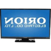
Value 20PVMV - Monitor ORION - Free user manual and instructions
Find the device manual for free Value 20PVMV ORION in PDF.


| Product Type | Professional Public View Monitor (PVM) LCD |
| Model | Value 20PVMV |
| Screen Size | 20" (diagonal) |
| Resolution (Max) | 640 x 480 @ 75Hz |
| Brightness | 450 cd/m² |
| Contrast Ratio | 400:1 |
| Aspect Ratio | 4:3 |
| Viewing Angle (H/V) | 170° / 170° |
| Response Time | <30ms |
| Display Colors | 16.2 million |
| Panel Lamp Life | 50,000 hours |
| Video System | NTSC / PAL / SECAM |
| Built-in Speaker | Yes (2W x 2) |
| Inputs | BNC In (1), BNC Out (2), S-Video In/Out (1/1), Audio In RCA (1) |
| Camera | Built-in WDR camera, tilt/swivel, 540 TVL, 0.1 Lux |
| Motion Detection | Microwave sensor (10-30 ft) with pop-up image |
| Filter Type | 3D Comb Filter / De-Interlace |
| LCD Protective Shield | Yes |
| Power Supply | AC100-240V or DC 12V/24V |
| Power Consumption (On) | <60W |
| Dimensions (W x H x D) | 18.93" x 18.01" x 3.0" |
| Cabinet Material | Powder coated metal, black (white optional) |
| Remote Control | Included (battery operated) |
| Cleaning | Unplug, use soft dry cloth; no chemical liquids |
| Safety | Do not open; ensure ventilation; stable installation |
Frequently Asked Questions - Value 20PVMV ORION
User questions about Value 20PVMV ORION
0 question about this device. Answer the ones you know or ask your own.
Ask a new question about this device
Download the instructions for your Monitor in PDF format for free! Find your manual Value 20PVMV - ORION and take your electronic device back in hand. On this page are published all the documents necessary for the use of your device. Value 20PVMV by ORION.
USER MANUAL Value 20PVMV ORION
PROFESSIONAL PUBLIC VIEW MONITOR (PVM) LCD

natural_image
Dark screen with a small circular logo and the word 'DRION' in the corner (no other text or symbols visible)20", 26", 32" TFT-LCD MONITOR (SECURITY)
Warning Statements
* Follow this safety instruction to use the monitor properly and prevent the damages.
* This safety instruction has “Warning” and “Caution” as below.
WARNING: If the user does not follow this instruction, it may cause the serious damage to the user.
CAUTION: If the user does not follow this instruction, it may cause the slight damage to the user or cause some damages to the monitor.
* Keep this user's guide book for later use.


Warning Statements


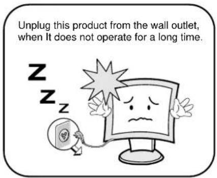

How to fix
- Do not open this product as it contains high voltage inside.
- It may create an electric shock.
- It the user disassembles and remove the back cover, it does not make sure
- To make up for the damages and do a service and exchange the monitor..
Cautions
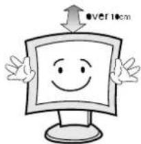
Install this monitor some distance From the wall and do not install unless Proper ventilation is provided.
natural_image
Cartoon illustration of a smiling computer monitor with arms and legs, no text or symbols presentPlace this product on a stable place. If not, it may fall, causing serious Damages to the monitor and people.

natural_image
Cartoon illustration of a computer monitor with a sad face and waving hands (no text or symbols)The openings must not be blocked by curtain, rug or other similar surface.

natural_image
Cartoon illustration of a computer monitor character with a sad face and frowning expression (no text or symbols)When carrying this monitor, be careful not to damage the panel and drop it. It may cause some trouble.

Before carrying the monitor, turn it off and Unplug the signal cables and the power code From the wall outlet.

natural_image
Cartoon illustration of a smiling computer monitor with a finger pointing at it, next to a small phone and a hand holding a magnifying glass (no text or symbols present)Take the power plug out from the wall outlet. Do not pull the cable. It may snap the inner wires and cause overheating and fire.

Install this monitor about 50cm far from the eyes and an angle of 0\~15 degrees below eyes. Too close installation may cause having weak sight.

Do not press the LCD panel with hands or the sharpened material hardly.

natural_image
Cartoon illustration of a sad computer monitor character holding a blank sign, with no text or symbols present.For cleaning, unplug the monitor from the Wall outlet. Do net use the liquid cloth. Use the soft cloth.
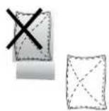

Do not use the chemical liquid for cleaning. It may cause fading and breakage.

TABLE OF CONTENTS
1. INSTALLATION 6
1.1 Parts 6
1.2 Connection (20 Inch) 7
1.3 Connection (26 & 32 Inch) 8
1.4 Remote Controller 9
2. FEATURES 10
2.1 Specifications (General) 10
2.2 Specifications (Card Reader) 11
3. OSD SETTING 12-20
3.1 OSD Menu Description (20 Inch) 12-15
3.2 OSD Menu Description (26 & 32 Inch) 16-20
4. CONTROL AND FUNCTIONS 21
- APPENDIX 22
- INFORMATION TO THE USER 23
- TROUBLESHOOTING 24
- LIMITED LIFETIME WARRANTY 25
INSTALLATION
1.1 Parts
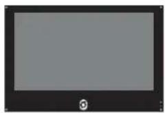
Remove the package cover and place the product on a flat and secure surface or in the installation location. Check whether all the following device and accessories are included with the main system.
natural_image
Computer monitor with blank screen and control knob (no text or symbols)Public View Monitor

User's Guide for PVMV

POWER CORD
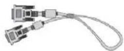
VGA CABLE
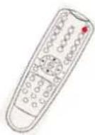
REMOCON

BATTERY
INSTALLATION
1.2 Connection (20 Inch PVMP)
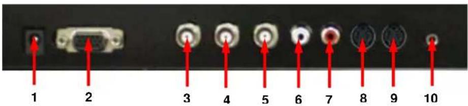
- DC 12V IN
- RGB IN
RGB signal input.
- CAMERA OUT
Composite signal input for AV1
- VIDEO 2 (AV2) IN
Video looping output for AV1
- VIDEO 2 (AV2) OUT
Composite signal for AV2
- AUDIO 1 IN
Stereo audio signal input. This input is for AV1, S-VIDEO
- AUDIO 2 IN
Stereo audio signal input. This output for AV2.
- S-VIDEO (Y/C) IN
Y/C separated signal input
- S-VIDEO (Y/C) OUT
Y/C separated signal looping output.
- PC STEREO IN
INSTALLATION
1.3 Connection (26 & 32 Inch PVMP)

-
HDMI In HDMI signal input
-
DVI IN DVI-D signal input
-
RGB IN RGB signal input
-
PC STEREO INPUT
-
COMPONENT IN YPbPr signal input
-
STEREO AUDIO IN Component stereo audio signal input
-
AUDIO 2 IN Stereo audio signal input. This output for VIDEO2.
-
AUDIO1 IN Stereo audio signal input. This output for VIDEO1 and S-VIDEO.
-
S-VIDEO (Y/C) OUT Y/C separated signal looping output
-
S-VIDEO (Y/C) IN Y/C separated signal input
-
VIDEO2 OUT Video looping output for VIDEO2
-
VIDEO2 IN Composite signal input for VIDEO2
-
VIDEO1 OUT Video looping output for VIDEO1
-
VIDEO1 IN Composite signal input for VIDEO1
-
CAMERA OUT
- AC INPUT
INSTALLATION
1.3 Remote Controller
A. SOURCE SELECT
Press the button to select the desired input source
B. PVM INPUT
□ POWER
Turn the monitor ON or OFF
□ MUTE
Temporarily silences the sound
□ COLOR TEMP
Adjust the color temperature of the screen.
□ SCAN MODE
Change the scan mode of the screen. (FULL / UNDER / OVER)
□ MENU/EXIT
Activates and exits the OSD menu
□ KEY LOCK
Prevent unauthorized operation of the equipment by locking the buttons
☐ STILLPIP: Activates/deactivates PIP/PBP mode
C. PIP MENU
PIP: Activates/deactivates PIP/PBP mode
P. INPUT: Selects an input source for the sub picture
P. LOC: Selects a location for the sub picture
P. S17F: Selects the size of the sub picture
P. SWAP:Swansthemainandsuk
P. SFT: Alternates between main and sub audio input

FEATURES
2.1 Specifications (General)
| VIDEO | |||
| Screen Size 20" 26" 32" | |||
| Max. Resolution 640 x 480 @ 75Hz 1366 x 768 @ 60Hz 1366 x 768 @ 60Hz | |||
| Pixel Pitch 0.6375 x 0.6375mm | 0.4215 x 0.4215mm 0.51 x 0.51mm | ||
| Brightness | 450 cd/m2 | 450 cd/m2 | 500 cd/m2 |
| Contrast Ratio 400 : 1 300 : 1 | 1200 : 1 | ||
| Aspect Ratio 4:3 16:9 | 16:9 | ||
| Viewing Angle (H/V) | 170° / 170° | 178° / 178° | 178° / 178° |
| Display Color | 16.2 Million 16.7 Million | 16.7 Million | |
| Response Time | < 30ms < 8ms | < 8ms | |
| Video System | NTSC / PAL / SECAM | NTSC / PAL / SECAM | NTSC / PAL / SECAM |
| Frequency (H) 31 ~ 48KHz | 30 ~ 64KHz | 30 ~ 64KHz | |
| Frequency (V) | 56 ~ 75Hz | 56 ~ 75Hz | 56 ~ 75Hz |
| Panel Lamp Life | 50,000 hours | 50,000 hours | 50,000 hours |
| INTERFACE | |||
| BNC In /Out | 1 / 2 | 2 / 3 | 2 / 3 |
| S-Video In / Out | 1 / 1 | 1 / 1 | 1 / 1 |
| VGA In (15Pin D-Sub) | 0 | 1 | 1 |
| Camera Out | 1 | 1 | 1 |
| DVI-D In / HDMI In | 0 / 0 | 1 / 1 | 1 / 1 |
| Audio In (RCA Type) | 1 | 3 | 3 |
| PC Stereo In | 0 / 0 | 1 / 1 | 1 / 1 |
| Remote Control | Yes | ||
| AUDIO | |||
| Built-In Speaker | Yes (2W x 2) | Yes (4W x 2) | Yes (4W x 2) |
| FEATURES | |||
| Filter Type | 3D Comb Filter / De-Interlace | ||
| LCD Protective Shield | Yes | ||
| Multi Language | English, Spanish, French | English, Spanish, French, German, Italian | |
| Motion Detection | Microwave Motion Sensor (10~30 feet) | ||
| Pop up Image | Upon Motion Detection or Sleep Mode | ||
| CAMERA | |||
| Camera Type | WDR Camera | WDR Camera | WDR Camera |
| Mechanical Design | Tilt Swivel Camera | ||
| Signal / Scanning System | NTSC | PAL | |
| Image Sensor | 1/3" SONY Super HAD CCD | ||
| Resolution | Horizontal : 540 TV Lines | ||
| Lens Mount | 4~9mm Vari-focal Lens(F=1.5) | ||
| Sensitivity | 0.1 Lux (Normal Mode) / 0.001 Lux (DSS Mode) | ||
| Electronic Shutter | 1/60 ~ 1/10,000 Sec | 1/50 ~ 1/10,000 Sec | |
| CABINET | |||
| Material / Color | Powder Coat Metal / Black (White Optional) | ||
| DIMENSION | |||
| Outline Dimension | 18.93" x 18.01" x 3.0" | 25.9" x 18.3" x 4.9" | 31.2" x 21.4" x 5.4" |
| POWER | |||
| Consumption : < On | < 60W | < 120W | < 150W |
| Electrical Ratings | AC100 ~ 240V or DC 12V or DC 24V | AC100 ~ 240V or DC 24V | |
NOTE : Technical specifications are subject to change without notice..
FEATURES
2.2 Specifications (Card Reader)
| SUPPORT STORAGE TYPE | |
| Compact Flash 8MB ~ 8GB | |
| Micro Drive / ST1 Driver 1GB, 2GB, 4GB / 2.5GB, 5GB, 6GB, 8GB | |
| Xd-Picture | 16MB~2GB: M-CARD, H-CARD |
| Multimedia Card 8MB~4GB, MMC Plus, MMC mobile, MMC micro | |
| Secure Digital 8MB~2GB, miniSD, microSD (SDHC,3GB~) | |
| Memory Stick / Duo 4MB ~ 128MB | |
| Memory Stick Pro / Duo 256MB | 512MB, 1GB, 2GB |
| SOCKET TYPE | |
| Socket | CF Type II, 4 in 1 Multi socket, USB socket |
| SUPPORT DATA TYPE | |
| Movie | Divx3, Divx4, Divx5 (.avi) / Xvid (.avi)MPEG-1(.mpeg / .mpg) / MPEG-2(.mpeg / .mpg) /MPEG-4(.mpeg / .mpg V3 avi) / A license for Dvix /MPEG-4 decode is required / UP to 800 x 450(under 4Mbps) |
| Music | MPEG-2, MPEG-1 layer 2, MP3, WMA, low complexity ACC,OGG(optional) 32KHz, 44.1KHz, 48KHz, 88.2KHz, 96KHz |
| Photo JPEG: JIFF, EXIF (.jpg), Baseline JPEG: below 5120 x 3840 | |
| Other | |
| Other Function | e-Book Play |
OSD (On Screen Display) SETTING
3.1 OSD MENU Description (20 Inch)
MENU SELECTION
- Press the MENU key to access the Main menu.
- Use the and arrow key to highlight a selection
- Press the OK or ▶ button to select an item.
- Use the and arrow key to highlight a selection.
- Use the and arrow key to adjust the setting on a selected item.
NOTE : If you don't connect RGB port, RGB SETUP menu is not select.
A. Input Select

Inputs can be set to VIDEO1, VIDEO2, S-VIDEO and RGB mode.
- Press the SOURCE button and then ▲/▼ button to move the source.
- Press the ▶ button to select the source.
- Press the MENU/EXIT button to exit the INPUT menu.
B. Picture Menu

OSD (On Screen Display) SETTING
- Press the MENU/EXIT key and then ▼/◄ or ▲/► key to select the PICTURE menu.
- Press the OK or ▶ button and then ▲/▶ button to select the adjustment item you need.
- Press the OK or ▶ button to active the item.
EX) If you select the BRIGHTNESS, then the picture below appears on the screen.

- Press the MENU/EXIT button to move the previous menu..
NOTE : TINT item is for the NTSC input only.
C. Sound Menu

- Press the MENU button and then ▲/▼ button to select the SOUND menu.
- Press the ▶ button and then ▲/▼ button to select the adjustment item you need.
- Press the ▶ button to active the item.
EX) If you select the TREBLE, then the picture below appears on the screen.

- Press the MENU button to move to the previous menu..
OSD (On Screen Display) SETTING
D. RGB Setup Menu

- Press the MENU button and then ▲/▼ button to select the RGB SETUP menu.
- Press the ▶ button and then ▲/▼ button to select the adjustment item you need.
- Press the ▶ button to active the item.
- Press the MENU button to move to the previous menu.
E. Function Menu

OSD (On Screen Display) SETTING
E. Function Menu (Continue)
- Press the MENU button and then ▲/▼ button to select the FUNCTION menu.
- Press the ▶ button and then ▲/▼ button to select the adjustment item you need.
- Press the ▶ button to active the item.
- Press the MENU button to move to the previous menu.
LANGUAGE : Select the language: English, French, German, Italian, Spanish.
DEAFULT : Select RESET to set the monitor to the factory default values.
OSD (On Screen Display) SETTING
3.2 OSD MENU Description (26 and 32 Inch)
A. Menu Selection
- Press the MENU key to access the Main menu.
- Use the ▲ and ▼ arrow key to highlight a selection
- Press the/SELECT key to select an item.
- Use the and arrow key to highlight a selection.
- Use the ◀ and ▶ arrow key to adjust the setting on a selected item.

bar
| Category | Value (%) | | :--- | :--- | | PICTURE | 70 | | CONTRAST | 51 | | BRIGHTNESS | 43 | | COLOR | 56 | | TINT | 80 | | SHARPNESS | 50 | | COLOR TEMP. | 50 | | RED | 50 | | GREEN | 50 | | BLUE | 50 | The chart displays a single bar for each category. The left side shows 'AUTO/▲' and 'SOURCE/▼', while the right side shows 'VOL' and 'SELECT'. The bottom section includes an arrow labeled '▲ / ▼ : MOVE' and an arrow labeled 'MENU/EXIT'.B. Input Select
Inputs can be set to VIDEO1, VIDEO2, S-VIDEO, RGB PC, DVI, HDMI, COMPONENT mode.

Press the ▶/SELECT key then you can change the input source.
OSD (On Screen Display) SETTING
C. Screen Menu

1. SCAN MODE
Select the screen size of main. (FULL / UNDER / OVER)
2. PIP
Select PIP mode. (OFF / ON / DW1 / DW2)
3. PIP INPUT
Select sub input of PIP mode. (VIDEO1 / VIDEO2 / S-VIDEO)
4. PIP SWAP
Select swap to interchange main with PIP
5. PIP SIZE
Select the PIP size. (SMALL / NORMAL / LARGE)
6. PIP R/T
Select the PIP position.
- R/B : Right Bottom
- L/B : Left Bottom
- R/T : Right Top
- L/T : Left Top
OSD (On Screen Display) SETTING
D. Setup Menu
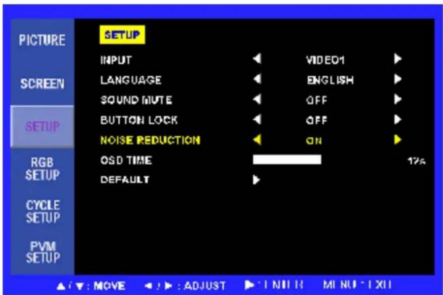
- INPUT Select input source. (VIDEO1 / VIDEO2 / S-VIDEO / RGB PC / DVI / HDMI / COMPONENT).
- LANGUAGE Select English, Italian, French, Spanish or German for the OSD display.
- SOUND MUTE Select OFF or ON. 'ON' silences the sound, 'OFF' return the sound.
- BUTTON LOCK Prevents unauthorized operation of the equipment by locking the buttons. Button lock feature by pressing the ◀ and ▲ buttons for 5 seconds.
- NOISE REDUCTION Reduces the background noise of the video signal.
- OSD TIME Select the OSD display time from 5 seconds to 30 seconds.
- DEFAULT Select restore to return to the factory setting.
OSD (On Screen Display) SETTING
E. PVM Setup Menu

1. MOTION MODE
Sets the video input which will be displayed when motion signal. (FULL /PIP/ DW1 / DW2)
2. MOTION INPUT
Select the input source of motion mode (VIDEO1 / VIDEO2 / S-VIDEO).
3. DWELL
Sets the time how long displayed on the screen of motion mode from 10 seconds to 60 seconds.
OSD (On Screen Display) SETTING
C. Menu Display
MAIN MENU
| PICTURE |
| SCREEN |
| SETUP |
| RGB SETUP |
| CYCLE SETUP |
| PVM SETUP |
PICTURE
| CONTRAST |
| BRIGHTNESS |
| COLOR |
| TINT |
| SHARPNESS |
| COLOR TEMP.: COOL / MEDIUM / WARM / LUSER (RED / GREEN / BLUE) |
SCREEN
| SCAN MODE : FULL /UNDER / OVER |
| PIP : OFF / ON / DW1 (WIDE PBP) / DW2 (FULL PBP) |
| PIP INPUT |
| PIP SWAP |
| PIP SIZE : SMALL / NORMAL / LARGE |
| PIP R/T (ROTATION) : R/B (RIGHT BOTTOM) |
| L/B (LEFT BOTTOM) |
| L/T (LEFT TOP) |
| R/T (RIGHT TOP) |
SETUP
| INPUT:VIDEO1/VIDEO2/S-VIDEO/RGB PC/DVI/HDMI/COMPONENT |
| LANGUAGE:ENGLISH/ITALIAN/FRENCH/SPANISH/GERMAN |
| SOUND MUTE |
| BUTTON LOCK |
| NOISE REDUCTION |
| OSD TIME:5~30 SECOND |
| DEFAULT |
RGB SETUP
| H-POSITION |
| V-POSITION |
| COLCK |
| PHASE |
| AUTO CONFIG. |
CYCLE SETUP
| CYCLE TIME : 10-30 SEC |
| CYCLE : ON / OFF |
| VIDEO 1 |
| VIDEO 2 |
| S-VIDEO |
| RGB PC |
| DVI |
| HDMI |
| COMPONENT |
| CAMERA |
| MEDIA |
PVM SETUP
| MOTION MODE : FULL / PIP / DW1 / DW2 |
| MOTION INPUT : ALL INPUT |
| DWELL : 10 ~ 60 SEC |
CONTROL AND FUNCTIONS
Menu/EXIT: Activates and exits the OSD.
SOURCE/▼: Select input source, and select the OSD menu.
AUTO/▲: Move the OSD menu and auto adjustment of RGB source.
▶/SELECT: Increase the level of volume and select the OSD menu.
◀ (VOL-): Decrease the level of volume and move the previous menu.

Turns the power ON or OFF. There will be a few seconds delay before the display appears.
The power LED(next to the power switch) lights with green when the power is turned ON.
The power is turned off by pressing the power switch again and the power LED goes Red.

LED LENSE, IR RECEIVE LENSE is located in front side.
APPENDIX
5.1 D-SUB Connector PIN Assignment
| PIN NO. | PIN Name | PIN NO. | PIN Name |
| 1 | RED VIDEO | 9 | NC |
| 2 | GREEN VIDEO | 10 | SIGNAL CABLE DETECT |
| 3 | BLUE VIDEO | 11 | GROUND |
| 4 | GROUND | 12 | SDA (for DDC) |
| 5 | GROUND | 13 | H-SYNC |
| 6 | RED GROUND | 14 | V-SYNC |
| 7 | GREEN GROUND | 15 | SCL (for DDC) |
| 8 | BLUE GROUND |

INFORMATION TO THE USER
This equipment has been tested and found to comply with the limits for a Class B digital device, pursuant to part 15 of the FCC Rules. These limits are designed to provide reasonable protection against harmful interference in a residential installation. This equipment generates, uses and can radiate radio frequency energy and, if not installed and used in accordance with the instructions, may cause harmful interference to radio communications. However, there is no guarantee that interference will not occur in a particular installation. If this equipment does cause harmful interference to radio or television reception, which can be determined by turning the equipment off and on, the user is encouraged to try to correct the interference by one more of the following measures:
● Reorient or relocate the receiving antenna.
- Increase the separation between the equipment and receiver.
- Connect the equipment into an outlet on a circuit different from that to which the receiver is connected.
- Consult the dealer or an experienced radio / TV technician for help.
WARNING:
The manufacturer is not responsible for any Radio or TV interference caused by unauthorized modifications to this equipment. Such modifications could void the user's authority to operate the equipment."
TROUBLESHOOTING
* When the following troubles are occurred, follow the trouble shooting. Before contacting a service center.
| Troubleshooting | Troubleshooting Tip |
| The screen doesn’t show up | 1. Make sure if the power supply is connected property |
| 2. Turn on the power. | |
| 3. Select the input signal right for the connected port. | |
| The screen is too light or to dark | Control the BRIGHTNESS |
| The screen size is not fit for the PC signal | Press the AUTO key among keys in the front.(It is used only in the PC signal) |
| The screen color shows strange in the PC signal | In the FUNCTION menu of OSD menu, perform the AUTO-ADJUST. |
2Year Limited Warranty
All Orion Images products carry a limited warranty from ship date against defects in materials and workmanship. Orion Images is not liable for improper installation that results in damage to mounts, adapters, display equipment or personal injury.
Contact Orion Images
In the event of missing and/or damage equipment, or technical questions, the following information can help in the completion of the installation.
Address: 7300 Bolsa Avenue, Westminster, CA 92683
Tel: 714-766-6300 / Fax: 714-766-6310
Email: sales@orionimages.com
Website: http://www.orionimages.com
- 20", 26", 32" TFT-LCD MONITOR (SECURITY)
- Warning Statements
- How to fix
- Cautions
- TABLE OF CONTENTS
- INSTALLATION 6
- FEATURES 10
- OSD SETTING 12-20
- CONTROL AND FUNCTIONS 21
- INSTALLATION
- Parts
- Connection (20 Inch PVMP)
- Connection (26 & 32 Inch PVMP)
- Remote Controller
- SOURCE SELECT
- PVM INPUT
- PIP MENU
- FEATURES
- Specifications (General)
- Specifications (Card Reader)
- OSD (On Screen Display) SETTING
- OSD MENU Description (20 Inch)
- MENU SELECTION
- Input Select
- Picture Menu
- Sound Menu
- RGB Setup Menu
- Function Menu
- Function Menu (Continue)
- OSD MENU Description (26 and 32 Inch)
- Menu Selection
- Input Select
- Screen Menu
- SCAN MODE
- PIP
- PIP INPUT
- PIP SWAP
- PIP SIZE
- PIP R/T
- Setup Menu
- PVM Setup Menu
- MOTION MODE
- MOTION INPUT
- DWELL
- MAIN MENU
- PICTURE
- SCREEN
- SETUP
- RGB SETUP
- CYCLE SETUP
- PVM SETUP
- CONTROL AND FUNCTIONS
- APPENDIX
- D-SUB Connector PIN Assignment
- INFORMATION TO THE USER
- WARNING:
- TROUBLESHOOTING
- 2Year Limited Warranty
- Contact Orion Images
Brand : ORION
Model : Value 20PVMV
Category : Monitor