
MP-R188W - Security Camera ZTE - Free user manual and instructions
Find the device manual for free MP-R188W ZTE in PDF.


| Product Type | Security Camera |
| Brand | ZTE |
| Model | MP-R188W |
| Dimensions (approx.) | 100 x 70 x 70 mm |
| Weight (approx.) | 200 g |
| Power Supply | DC 5V via USB cable (adapter included) |
| Video Resolution | 1080p Full HD |
| Field of View | 120° wide angle |
| Night Vision | Infrared LED up to 10 meters |
| Audio | Two-way audio with built-in microphone and speaker |
| Motion Detection | Yes, with push notifications |
| Connectivity | Wi-Fi 802.11 b/g/n (2.4 GHz) |
| Storage | Cloud storage (subscription) and microSD card slot (up to 128 GB, not included) |
| Compatible Devices | iOS and Android smartphones via ZTE app |
| Weather Resistance | Indoor use only |
| Mounting | Tabletop stand and wall mount bracket included |
| Security Features | Encrypted video stream, user account protection |
| Maintenance | Clean lens with soft dry cloth; keep away from moisture |
| Spare Parts | Power adapter, USB cable, mounting screws (available from ZTE support) |
Frequently Asked Questions - MP-R188W ZTE
User questions about MP-R188W ZTE
0 question about this device. Answer the ones you know or ask your own.
Ask a new question about this device
Download the instructions for your Security Camera in PDF format for free! Find your manual MP-R188W - ZTE and take your electronic device back in hand. On this page are published all the documents necessary for the use of your device. MP-R188W by ZTE.
USER MANUAL MP-R188W ZTE
ZNNC MP-R188W-95-NC1T-B
User Manual
ZTE USA Inc.
2425 N Central Expressway, Suite 600,
Richardson TX. 75080
Technical Support Website:
http://enterprise.zte.com.cn/us/
E-mail: enterprisesupport@zteusa.com
LEGAL INFORMATION
The contents of this document are protected by copyright laws and international treaties. Any reproduction or distribution of this document or any portion of this document, in any form by any means, without the prior written consent of Shenzhen ZNV Technology Co., Ltd. (ZNV for short) is prohibited. Additionally, the contents of this document are protected by contractual confidentiality obligations.
All company, brand and product names are trade or service marks, or registered trade or service marks, of ZNV or of their respective owners.
This document is provided "as is", and all express, implied, or statutory warranties, representations or conditions are disclaimed, including without limitation any implied warranty of merchantability, fitness for a particular purpose, title or non-infringement. ZNV and its licensors shall not be liable for damages resulting from the use of or reliance on the information contained herein.
ZNV or its licensors may have current or pending intellectual property rights or applications covering the subject matter of this document. Except as expressly provided in any written license between ZNV and its licensee, the user of this document shall not acquire any license to the subject matter herein.
The contents of this document and all policies of ZNV, including without limitation policies related to support or training are subject to changes without notice.
Revision History
| Date | Revision No. | Serial No. | Reason for Revision |
| 6/12/2012 | R1.0 | First Edition | |
| 9/23/2013 | R1.1 Working temperature updated | ||
Contents
About This Manual .... i
Purpose ....i
Conventions ...... i
Safety Signs .... ii
Chapter 1 .... 1
Product Overview .... 1
Naming Conventions ....1
Appearance....2
Main Features....3
Chapter 2....7
Installation....7
Installation Precautions....7
Dimensions 8
Installation Modes....9
Wall-Mounting....9
Suspension Mounting 12
Wall Corner Mounting.... 15
Pole-Mounting Mode 18
Counterfort Mounting 21
Dome Installation 23
Dome Installation 23
Memory Card Installation.... 24
Wire Connections for the Dome 25
Chapter 3....31
Operating Instructions 31
Power-on Self-Test....31
Operations for Basic Functions 31
Operations for Special Functions 32
Character Prompts on the Screen 33
Chapter 4 ....35
Configuration and Operation 35
Configuration Flow 35
Login 35
Configuring Network Parameters....36
IP Address Setting 36
PPPOE Dialup Setting 38
Logging in to or Restarting the Camera 39
Setting the Access Server IP Address....40
Setting the Device ID 41
Configuring I/O Parameters....41
Setting Channel Parameters 42
Viewing a Video....42
Video Query....43
Setting Preset Positions 45
Setting Encoding Parameters....46
Setting OSD Parameters 46
Setting Titles....47
Setting a Storage Schedule 49
Setting Alarm Parameters .... 50
Basic Alarm Parameters....50
Setting DI Linkage Parameters....51
System Configuration 51
Checking Device State....51
Storage Medium Management....53
Time Synchronization....54
User Management....54
Log Query....57
Device Upgrade 58
Chapter 5....59
Menu Operation....59
Menu Overview....59
Password Screen....60
Main Menu 61
Configuration 62
Camera Basic Parameters 67
Camera Advanced....72
Mask Zone 80
Integrated PTZ....83
Other Functions.... 93
Restart 95
Exit 95
Appendix A....97
Terms and Abbreviations....97
Appendix B....101
FAQ....101
Questions on Images.... 101
Questions about the Controller.... 101
Questions about the Installation.... 102
Appendix C....105
Connect to the ZXVNMS Platform....105
Creating the Encoder and Camera on the Management Client ..... 105
Write ZXVNMS Information into the Camera 110
Appendix D....113
Wire Gauge Conversion Table 113
Appendix E 115
Factory Default Settings Table 115
Appendix F 117
Technical Parameters Table 117
About This Manual
Purpose
The ZNNC MP-R188W-95-NC1T-B dome is a video monitoring terminal developed by ZNV. This manual introduces the functional features, structure, installation, usage, operations and FAQs of the product.
This manual is applicable to ZNNC MP-R188W-95-NC1T-B, ZNNC MP-R202W-95-NC1T-A, ZNNC MP-R202W-95-NC3T-A, ZNNC MP-R202W-95-NC1T-B, ZNNC MP-R202W-95-NC3T-B. Before using this manual, please make sure the product model is applicable.
Conventions
Typographical Conventions
ZNV documents employ the following typographical conventions.
TABLE 1 TYPOGRAPHICAL CONVENTIONS
| Typeface Meaning | |
| Italics References | to other Manuals and documents. |
| "Quotes" Links on screens. | |
| Bold Menus, menu options, function names, input fields, radio button names, check boxes, drop-down lists, dialog box names, window names. | |
| CAPS Keys on the keyboard, buttons on screens and company name. | |
| Constant width | Text that you type, program code, file and directory names, and function names. |
| Optional parameters. | |
| { } Mandatory parameters. | |
| [YS6] | Note: Provides additional information about a certain topic. |
| [A58x] | Checkpoint: Indicates that a particular step needs to be checked before proceeding further. |
| [W46z] | Tip: Indicates a suggestion or hint to make things easier or more productive for the reader. |
Mouse Operation Conventions
TABLE 2 MOUSE OPERATION CONVENTIONS
| Typeface Meaning | |
| Click Refers to | clicking the primary mouse button (usually the left mouse button) once. |
| Double-click Refers to quickly clicking the primary mouse button (usually the left mouse button) twice. | |
| Right-click Refers to clicking the secondary mouse button (usually the right mouse button) once. | |
| Drag Refers to | pressing and holding a mouse button and moving the mouse. |
Safety Signs
TABLE 3 SAFETY SIGNS
| Safety Signs | Meaning |
 | Danger: Indicates an imminently hazardous situation, which if not avoided, will result in death or serious injury. This word should be limited to extreme situations. |
 | Warning: Indicates a potentially hazardous situation, which if not avoided, could result in death or serious injury. |
 | Caution: Indicates a potentially hazardous situation, which if not avoided, could result in minor or moderate injury. It may also be used to alert against unsafe practices. |
Preventive Measures
Preventive measures are designed to ensure that users can use this product correctly, avoid dangers and property losses. Preventive measures contain the following two parts:
■ Safety Warnings: Alert users to potential dangers which may cause death or serious injuries.
■ Safety Cautions: Alert users to potential dangers which may cause damages or property losses.

Safety Warnings
- All installation and operation should conform to your local electrical safety codes.
-
Please use a power adapter supplied by a qualified manufacturer. This product is supplied with AC24V/2.5A or DC12V-48V/3A.
-
Do not connect multiple cameras to the same power adapter. Fire may result due to overheating if the load is exceeded.
-
Make sure the power is disconnected before wiring or dismounting the unit.
-
Make sure the camera is firmly installed.
-
If this product does not work properly, please contact your local dealer or qualified technician. Do not dismantle or repair the product yourself. Any damage resulting from unauthorized repair or failure to follow instructions will not be covered in the warranty of the company.

Safety Cautions
-
Avoid installing the camera where it would be subject to violent impact or magnetic interference.
-
Do not expose the camera to extremely hot or cold temperature (the operating temperature must be in the range of -30°C - +60°C , -22°F - +140°F ), or a dusty, damp or vibrating environment. Otherwise the camera may be damaged or the performance may be degraded.
-
Do not direct the camera lens to an object with strong light, such as the sun or an incandescent lamp.
-
Do not install the camera in places near a heat source or with poor ventilation, such as a heater.
-
When cleaning the lens, wipe it only with a clean and dry soft cloth. If the dirt is still there, clean it with a diluted neutral detergent and dry it.
Chapter 1
Product Overview
The ZNNC MP-R188W-95-NC1T-B High Speed Dome (hereinafter referred to as Dome) supports two signal standards: NTSC and PAL. The dome has an integrated high-performance digital signal processing (DSP) camera module and features high definition and distinct images. The dome also has a built-in multi-protocol decoder and a high-speed Pan/Tilt. Driven by a precision motor, the PTZ (Pan Tilt Zoom) is sensitive in reaction and smooth running (with no vibration). With a built-in IR lamp zoom module and IR lamp focus module, the dome features an excellent night viewing effect and is stable in operation as well as easy to use and maintain.
With outstanding performance and comprehensive functions, the ZNNC MP-R188W-95-NC1T-B High Speed Dome becomes a high-tech monitoring product in the security field. It can be widely applied to highways, urban streets, plazas, subways, banks, airports, hospitals, bazaars, supermarkets, shopping malls, schools, densely-populated mining enterprises, frontier stations, casinos, prisons, upscale residences, etc.
Naming Conventions
The ZNNC MP-R188W-95-NC1T-B High Speed Dome is one of the ZNNC MP-R series. The naming conventions are as shown in Table 4.
TABLE 4 MODEL DESCRIPTION
| Model ZNNC MP-RXXXX-XX-XXXX-X | |
| Definition | |
| ZNNC MP-R | ZNNC indicates that the IP Camera is manufactured by ZNV; MP stands for a mega-pixel camera; R means infrared. |
| XXXX | The first two digits indicate the optical lens zoom rate.The third digit indicates the light environment:1: 1.3 mega CCD day & night camera2: 2 mega CMOS day & night cameraThe fourth digit indicates indoor or outdoor:W: outdoor, N: indoor. |
| -XX | Indicates the installation mode and manufacturing information, made up of a letter and a digit: 95: mounted with a bracket provided by the user. |
| -XXXX | The first two digits indicate whether it is equipped with wireless mode, made up of letters: NC: with no wireless mode.The third digit indicates the supply voltage, indicated by letter.The fourth digit indicates the video system: A indicates PAL and NSTC system compatible. |
| -X | Indicates the serial number of the dome camera :A: Sony; B: Hitachi. |
Appearance
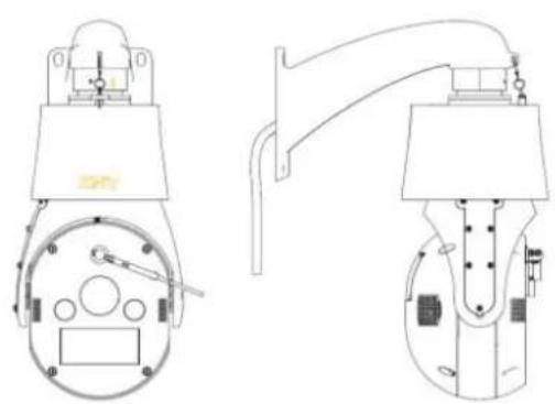
- A wall-mounted camera is as shown in Figure 1.
FIGURE 1 MOUNTED ON WALL
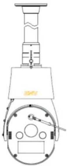
- A suspension-mounted camera is as shown in Figure 2.
FIGURE 2 MOUNTED ON CEILING
Main Features
- Driven by a precision stepping motor, the camera works smoothly without vibration and noises.
- High reliability, the internally configured parameters will not be lost in the event of power outage.
The system can display information, such as the PTZ position, dome title, preset title, zonetips title, pattern title, auto scan title, zoom rate, time, and temperature.
■ Equipped with a built-in function menu where you can adjust the camera parameters and set the PTZ function.
- The menu items are automatch with functions of the camera module.
The camera supports such functions as wide dynamic range, digital slow shutter, noise reduction, and image stabilization (depending on the camera module).
■ The IR lamp supports Smart mode.
- Local zoom.
■ Color/B&W mode.
360° continuous horizontal rotation, 30\~90° vertical rotation, and auto flip function.
■ Manual horizontal speed: 0.1\~160°/s, manual vertical speed: 0.1\~120°/s; maximum preset horizontal speed: 260°/s, (and) maximum preset vertical speed: 200°/s.
■ 256 presets and the preset error is less than 0.5 degrees.
- It supports 8 AutoCruise Tracks and each can be set to 24 presets. The retention period of the preset can be set.
■ Supports 4 AutoScan items and the scan speed class can be set as 1 to 255.
■ Supports 4 Pattern items and each scan path can store 1,000 commands.
■ Supports 8 Zone tips and 24 Masks (depending on the camera module).
■ Supports 2 channels of alarm input and 2 channels of alarm output.
■ Supports the Proportional Pan and North Reference functions.
- The internal dome provides a temperature monitoring function and the temperature display mode can be set.
- The camera supports a real-time clock, and the clock display mode can be set.
■ Supports the power-on recovery function, which can specify the action of the dome after power recovery or restore the dome status before power off through the dome core menu.
■ Supports the Schedules function, which can specify the action of the dome at a specified time through the dome core menu.
■ Supports the Action at Idle function, which can specify the action of the dome during idle through the dome core menu.
- It provides a 6-digit user password and a 10-digit super user password.
■ The dome complies with the IP66 standard.
- The power supply, video, and communication ports of the dome reach 4000V surge protection.
The audio, network port and DI/DO reach 2000V surge protection.
■ Video compression adopts H.264 compression technology, and the encoding specification can be up to High Profile, whose performance is highly-effective, stable and reliable.
■ Supports coding stream settings. The maximum code stream is 8192 kbps, while the minimum is 16 kbps.
■ Supports OSD time display and ODS name display.
■ Supports multiple resolution and frame rate settings.
■ Supports the setting for main code stream and the setting range for frame rate is 1 to 60fps.
■ Supports DO alarm parameter settings including the DO channel number, output delay time, and arming time.
■ Supports TCP/IP, UDP, RTP/IP, HTTP, XML, Telnet, and DHCP.
■ Supports a Micro-SD card, maximum 32GB.
■ Supports 1-channel analog video output interface.
■ Auto focus.
In auto focus mode, the integrated mechanism focuses automatically to keep the image clear. You can press Focus + and Focus – to adjust the distance of the focus point. However, when the PTZ moves horizontally or vertically, or the lens zooms, the integrated mechanism will restore to the auto focus function.
■ Auto flip
The dome camera rotates to 90 degrees vertically down and stays for about 1 second, then automatically rotates 180 degrees horizontally. This will help the camera monitor vertically in the range of 180 degrees.
■ Auto iris
In auto iris mode, the integrated mechanism adjusts the size of the iris automatically to keep the image clear. You can press Iris + and Iris - to adjust the light quantity of the iris. However, when the PTZ moves horizontally or vertically, or the lens zooms, the integrated mechanism will restore to the auto focus function.
■ Preset
Each preset contains such information as the PTZ level, upright position, and lens zoom parameters. When invoking the preset, the dome automatically runs with the status of the preset information. You can define, modify, delete or invoke presets.
■ Proportional pan
With the Proportional Pan function enabled, the velocity of movement in horizontal and vertical directions will change when the zoom ratio is changed. When the zoom ratio increases, the moving speed of the dome will slow down automatically. When the zoom ratio decreases, the moving speed of the camera will speed up automatically, so that a better object tracking effect can be obtained. This function is On by default.
Day/Nite mode
The dome camera has the Day/Nite Mode function. In auto mode, the integrated mechanism will switch to color display or day & night display according to the environmental light changes.
- Alarm linkage
The dome can accept 2-way alarm input signals. You can also turn off alarm input. The video recording function can be linked to start when the camera detects the alarm input signal.
- Alarm auxiliary output
The dome is equipped with a 2-way alarm auxiliary switch which can be set to trigger or control other related devices. You can configure which alarm output channel to be triggered when an alarm arrives. The alarm auxiliary output can be set to On or Off.
■ Partial magnification
You can select this function in Windows Internet Explorer. When the function is selected, the selected objects will be enlarged to the entire screen and lie in the center of the video screen.
■ Centered by clicking
You can select this function in Internet Explorer. When this function is selected, the selected object will lie in the center of the video screen.
■ Voice talk back
You can turn the voice talkback function on or off. With this function turned on, both the voice from the site and the voice from the device can be recorded.
- Recording
The dome camera supports timing recording, DI alarm linkage recording, manual recording, video and audio composite recording, local recording and storage media recording. The maximum capacity storage media supported is a 32GB Micro SD memory card.
■ Network parameter configuration
You can set network parameters: device IP address and control port, PPPOE dialing, management host address, (the IP address and control port IP address have a subnet mask, gateway address, main DNS, alternative DNS, SIP port and control port available for configuration).
Log query
The dome camera supports period log query, alarm log query and operation log query. The DI alarm log can be queried by alarm log query. Operation logs can be queried by starting, shutdown, improper shutdown, remote login, remote logout, remote parameter setting, local playback by file, local playback by time, local recording starting, local recording stop, remote restarting, remote upgrade, and remote PTZ control.
■ Management control
Management control includes remote upgrade, remote reset, self-diagnosis and multi-user rights management. Multi-user rights management includes normal user and super user. A super user has full control over the device, while a normal user has some control over the device. Normal users' permissions can be authorized.
Chapter 2
Installation
Installation Precautions
-
Please read this manual carefully before installing the ZNNC MP-R188W-95-NC1T-B camera.
-
Please use the indicated power type and voltage. The rated voltage is AC24V or DC12-48V. If the voltage is too high or too low for a long time, the dome camera may be damaged and work improperly.
-
Do not expose the camera lens to objects with strong light. Otherwise, the CCD performance may be degraded, resulting in no image or image distortion.
-
The ZNNC MP-R188W-95-NC1T-B camera features excellent waterproof and dustproof performance, up to IP 66 international standard. If the dome camera is wired and installed in a wrong way, rain water may travel along the cable and enter the infrared high speed dome mechanism, causing a short circuit to the circuit board, even damaging the camera. If the camera is installed correctly, as shown in Figure 3, the cables cling to the lower fringe of the mounting bracket. If not, as shown in Figure 4, the cables cling to the upper fringe of the mounting bracket.
FIGURE 3 CORRECT INSTALLATION MODE

FIGURE 4 INCORRECT INSTALLATION MODE

Dimensions
The dimensions of the ZNNC MP-R188W-95-NC1T-B camera and its connector are as shown in Figure 5 and Figure 6.
FIGURE 5 DIMENSIONS OF THE CAMERA
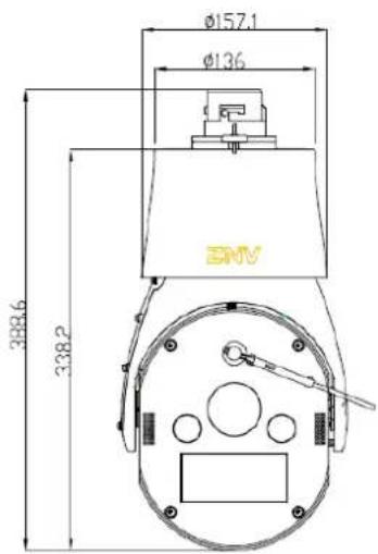
FIGURE 6 DIMENSIONS OF THE CONNECTOR


Installation Modes
There are five installation modes for the ZNNC MP-R188W-95-NC1T-B High Speed Dome: wall-mounting, suspension-mounting, wall corner-mounting, pole-mounting, and counterfort-mounting. This section introduces mounting parts and installation steps of these five installation modes.
Wall-Mounting
Wall-mounting is applicable to indoor and outdoor hard wall structures. The installation environment must meet the following requirements:
● The wall must be thick enough to mount expansion bolts.
- The wall must be able to endure at least eight times the weight of the high-speed dome and its accessories.
Mounting Parts
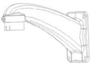
1. Wall-mount bracket
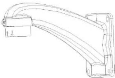
It comes with the dome camera. The wall-mount bracket is as shown in Figure 7.
FIGURE 7 WALL-MOUNT BRACKET
2. Wall-mount bracket accessories
Four M8x30 expansion bolts, four M8 nuts, four spring washers and four flat washers (provided by the user)
Installation Steps
1. Drill holes and mount expansion bolts.
According to the position marks of holes of the wall-mount bracket, drill four holes in the wall with an electric drill, as shown in Figure 8. Insert M8 expansion bolts (provided by the user) into the holes.
FIGURE 8 INSTALL THE EXPANSION BOLTS

2. Mount the wall-mount bracket.
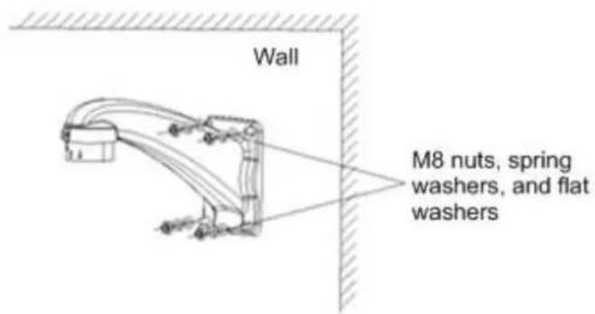
There are three line outlets on the mounting bracket. Select one outlet, remove the thin wall with pliers and debur it. Lead cables (control line, video cable, alarm line, and power wire, etc.) through the mounting bracket. Align the bracket holes with the four expansion bolts and attach the bracket to the wall with four M8 nuts with spring washers and flat washers, as shown in Figure 9, Figure 10 and Figure 11.

Note:
Use pliers to clean up the thin wall of the line outlet to avoid scraping cables.
FIGURE 9 FASTENING THE WALL-MOUNT BRACKET

FIGURE 10 LINE OUTLET OF THE MOUNTING BRACKET

FIGURE 11 MOUNTING THE BRACKET
- Mount the dome.
Refer to section Dome Installation.
Suspension Mounting
- Indoor suspension mounting is applicable to hard ceiling structures. The indoor installation environment must meet the following requirements:
i. The ceiling must be thick enough to mount expansion bolts.
ii. The wall must be able to endure at least five times the weight of the camera and its accessories.
● Outdoor suspension mounting is applicable to suspension arm structures which must meet the following requirements:
i. Completely sealed.
ii. The suspension arm structure must be able to endure at least eight times the weight of the camera and its accessories.
Mounting Parts for Indoor Suspension
- An indoor ceiling-suspended bracket consists of four parts: a bracket base, a pole, a joint, and an adapter. The length of the pole can be customized according to actual requirements (the standard length is 300mm), as shown in Figure 12.
FIGURE 12 MOUNTING PARTS FOR INDOOR SUSPENSION MODE

- Bracket accessories:
Four M8 expansion bolts, nuts, spring washers and flat washers (provided by the user)
Four M4 screws and one M5 screw (provided by the user)
Installation Steps for Indoor Suspension Mounting
1. Mount the bracket base.
According to positions of the holes at the bracket base, drill four 8mm-diameter holes with an electric drill in the ceiling. Insert M8 expansion bolts into the holes, and then lead cables (control line, video cable, alarm line, and power wire) through the cable trough on the side of the bracket base. Align the bracket holes with the four expansion bolts and attach the bracket to the wall with four M8 nuts with spring washers and flat washers, as shown in Figure 13.
FIGURE 13 MOUNTING THE BRACKET BASE


Note:
The length of the outlet line depends on the length of the selected pole.
2. Mount the pole, joint and bracket adapter.
Screw the joint to the pole and fasten it with M4 screws. Then screw the adapter to the joint and fasten it with M4 screws. Preset M5 screws. Lead cables through the pole, screw the pole to the bracket base and fasten the base with M4 screws, as shown in Figure 14.
FIGURE 14 MOUNTING THE POLE, JOINT AND ADAPTER

- Mount the dome camera.
Refer to section Dome Installation. The installation is as shown in Figure 15.
FIGURE 15 INDOOR SUSPENSION

Mounting Parts for Outdoor Suspension
- Suspension arm
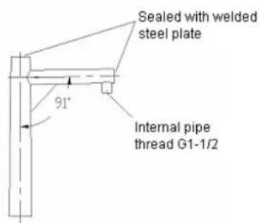
A suspension arm is made of steel pipe. It is commonly fitted on the pole, and customized or provided by the user, as shown in Figure 16. The suspension arm stretches up, being 91° to the pole so as to prevent rain from entering the dome camera. The end ports are sealed with welded steel plate. The threaded connection for mounting the dome is the internal pipe thread G1-1/2. There is a thin wire inside the pipe of the suspension arm and the pole, which is used to pull back cables.
FIGURE 16 OUTDOOR SUSPENSION ARM INSTALLATION
- Adapter
FIGURE 17 ADAPTER
Installation Steps for Outdoor Suspension Mounting
- Mount the suspension arm.
The installation methods differ with different suspension arms. Usually, a suspension arm can be fitted on the pole. Tie cables to the thin wire and lead them through the pipe by pulling back the thin wire.
-
Screw the adapter to the suspension arm, and fasten it with M5 screws.
-
Mount the dome camera.
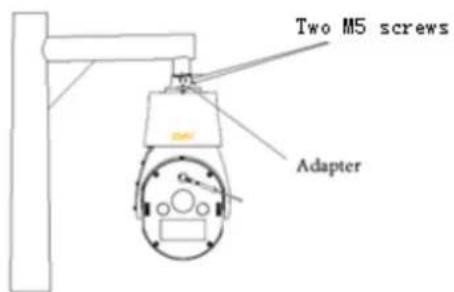
Refer to section Dome Installation. The installation is as shown in Figure 18. Screw in M5 screws.
FIGURE 18 OUTDOOR SUSPENSION
Wall Corner Mounting
Wall corner mounting is applicable to indoor and outdoor hard wall structures with an angle of over 90° . The installation environment must meet the following requirements:
-
The wall must be thick enough to mount expansion bolts.
-
The wall must be able to endure eight times the weight of the dome and its accessories.
Mounting Parts
1. Wall-mount bracket
FIGURE 19 WALL-MOUNTING BRACKET
2 Corner-mount bracket
A corner-mount bracket is as shown in Figure 20. To mount a dome camera on a wall corner, use a corner-mount bracket together with a wall-mounting bracket.
FIGURE 20 CORNER-MOUNT BRACKET

3. Mount accessories
Six M8×30 expansion bolts, nuts, spring washers, and flat washers, as well as four M8×25 screws, spring washers, and flat washers (provided by the user).
Installation Steps
1. Mount the corner-mount bracket.
According to mark positions of the holes of the corner-mount bracket, drill six 8mm-diameter holes with an electric drill. Insert M8 expansion bolts into the holes. Lead cables (control line, video cable, alarm line and power wire) through the center hole of the corner-mount bracket. Align the bracket holes with the six expansion bolts and attach the bracket to the wall with six M8 screws with spring washers and flat washers.

Note:
The steel expansion bolts are provided by the user. Please make sure that the length of the outlet line is enough.
FIGURE 21 MOUNTING THE CORNER-MOUNT BRACKET

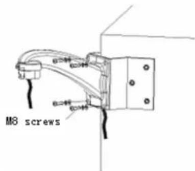
- Mount the wall-mounting bracket.
Lead cables (control line, video cable, alarm line and power wire) through the wall-mounting bracket. Screw the wall-mounting bracket by using four M8 screws with spring washers and flat washers, as shown in Figure 22.
FIGURE 22 MOUNTING THE WALL-MOUNTING BRACKET
- Mount the dome.
Refer to section Dome Installation. The installation is as shown in Figure 23. Screw in M5 screws.
FIGURE 23 WALL CORNER MOUNTING EFFECT

Pole-Mounting Mode
Pole-mounting mode is applicable to indoor and outdoor hard columnar form structures. The installation environment must meet the following requirements:
- The diameter of the columnar structure must meet the installation dimension requirements of the clamp.
- The columnar structure must endure at least eight times the weight of the dome and its accessories.
Mounting Parts
- Wall bracket
A wall bracket is as shown in Figure 24.
FIGURE 24 WALL BRACKET

- Pole-mount bracket
A pole-mount bracket is as shown in Figure 25. To mount the dome camera on the pole, use a pole-mount bracket together with a wall-mounting bracket.
FIGURE 25 POLE-MOUNT BRACKET

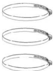
- Clamp
A clamp (as shown in Figure 26) is used together with a pole-mount bracket. The diameter adjustment range of a standard clamp is: 20 mm -130 mm. The clamp size can also be customized according to your requirements.
FIGURE 26 CLAMP
4. Mount accessories
Four M8×25 bolts, spring washers and flat washers (provided by the user)
Installation Steps
1. Assemble the pole-mount bracket.
Unscrew three clamps with a screwdriver, and lead them through the rectangular holes on the pole-mount bracket, as shown in Figure 27.
FIGURE 27 ASSEMBLING THE POLE-MOUNT BRACKET

2. Mount the pole-mount bracket.
Lead cables (control line, video cable, alarm line and power wire) through the center hole on the pole-mount bracket. Brace the three clamps and clamp them to the pole for mounting, and then screw them on with bolts by using a screwdriver, as shown in Figure 28.
FIGURE 28 MOUNTING THE POLE-MOUNT BRACKET

3. Mount the wall-mounting bracket.
Lead cables (control line, video cable, alarm line and power wire) through the wall-mounting bracket, and then fasten the bracket to the pole-mount bracket using four M8 screws with spring washers and flat washers, as shown in Figure 29.
FIGURE 29 MOUNTING THE WALL-MOUNTING BRACKET

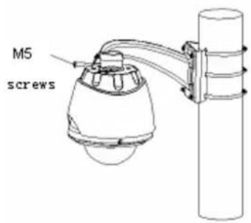
4. Mount the dome.
Refer to section Dome Installation. The installation is as shown in Figure 30. Screw in M5 screws.
FIGURE 30 POLE-MOUNTING EFFECT
Counterfort Mounting
Counterfort mounting mode is applicable to outdoor hard wall structures. The installation environment must meet the following requirements:
- The wall must be thick enough to mount expansion bolts.
- The wall must be able to endure at least eight times the weight of the dome and its accessories.
Mounting Parts
- Counterfort-mount bracket
The appearance of a counterfort-mount bracket is as shown in Figure 31 (unit: mm).
FIGURE 31 COUNTERFORT-MOUNT BRACKET

- Adapter
FIGURE 32 ADAPTER
External pipe thread G1-1/2

3. Mount accessories
Ten M8×30 expansion bolts, nuts, spring washers and flat washers; four M8×25 screws, spring washers and flat washers (provided by the user)
Two M5 screws, two M6 screws, and four M6 nuts (provided by the user)
Installation Steps
- Drill and install expansion bolts.
According to mark positions of the holes of the bracket base plate on the counterfort, drill 10 holes with an electric drill, and then insert M8 expansion bolts into the holes.
- Mount the counterfort-mount bracket.
According to mark positions of the holes of the bracket, drill ten 8mm-diameter holes with an electric drill, and then insert M8 expansion bolts into the holes. Align the bracket holes with the ten expansion bolts and attach the bracket to the wall by screwing in ten M8 screws with spring washers and flat washers. Lead cables (control line, video cable, alarm line and power wire) through the suspender of the counterfort-mount bracket. Revolve the suspender to an appropriate angle. Screw in four M6 nuts to press the securing plate against the suspender of the counterfort-mount bracket, and then screw in two M6 screws.
-
Screw in the adapter to the suspender of the counterfort-mount bracket, and then fasten it with M5 screws.
-
Mount the dome.
Refer to section Dome Installation. The installation is as shown in Figure 33. Screw in M5 screws.
FIGURE 33 COUNTERFORT-MOUNTING
Dome Installation
Dome Installation
1. Mount the dome bracket.
Lead cables (control line, video cable, alarm line, and power wire) through the dome bracket, as shown in Figure 34.
FIGURE 34 DOME BRACKET INSTALLATION
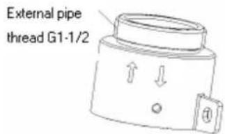
Note: Except for standard wall-mounting brackets, other kinds of brackets must be mounted in conjunction with an adapter. The external pipe thread of the adapter is G1-1/2. The connection procedure of the adapter and the dome is the same as that of the standard wall-mounting bracket and the dome.
2. Mount the dome camera.
Take out the dome from the packing case. Buckle the safety rope of the dome to the bracket, and then connect the cables (control line, video cable, alarm line, and power wire) according to the marks. Mount the dome on the wall-mounting bracket, and then screw in M5 screws with a Phillips screwdriver, as shown in Figure 35.
FIGURE 35 DOME UPPER COVER INSTALLATION
Mount the upper cover on the wall bracket according to the following steps, as shown in Figure 36.
i. Align: Align the boss of the upper cover connector, which is close to the counter bore, to the threaded hole of the bracket.
ii. Pull up: Push the adapter up to the end of the inner bore of the bracket.
iii. Rotate right: Rotate the adapter right to the end.
iv. Pull down: Pull the connector down to the bottom part. Then the threaded hole of the bracket is aligned with the counter bore of the connector.
FIGURE 36 MOUNT THE UPPER COVER ON THE WALL BRACKET
Note:
Draw out the cables gently to prevent the connector from being pulled out or the cables from being disconnected.
Waterproofing treatment must be applied to the cable connections.
Memory Card Installation
The dome supports a maximum of a 32GB Micro SD card. The memory card slot is located on the internal board of the dome mechanism. For easy installation, open the slot door on the back cover of the dome, and then push the Micro SD card into the slot, as shown in Figure 37.
FIGURE 37 INSTALL A MICRO-SD CARD

Wire Connections for the Dome
- Connect the power wire, video cable, and control line.
The wiring of the dome (video cable, control line, and power wire) is as shown in Figure 38. Refer to Table 5 for detailed descriptions.
FIGURE 38 WIRING DIAGRAM
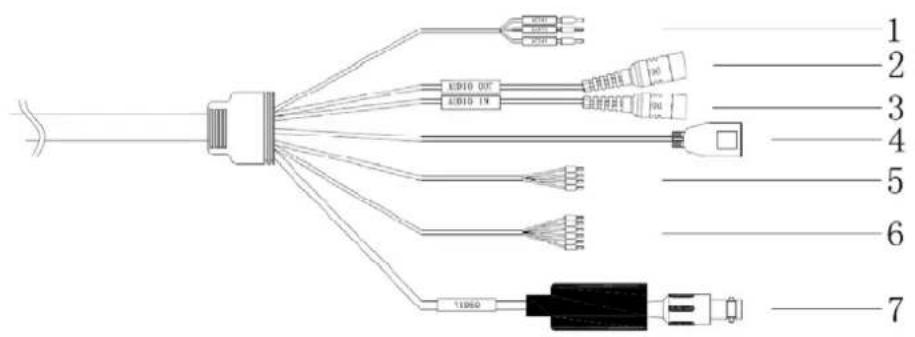
TABLE 5 WIRING DESCRIPTION
| SN Label Pin Color | ||
| 1 Power wire | AC24V Red | |
| EARTH Yellow |
| SN Label Pin Color | |||
| AC24V Black | |||
| 2 | Audio input | AUDIO_IN | White audio connector |
| 3 | Audio output | AUDIO_OUT | Yellow audio connector |
| 4 | Ethernet port | Black RJ45 connector | Black RJ45 connector |
| 5 Alarm input line | DI1 Pink | ||
| COM Brown | |||
| DI2 purple | |||
| COM Blue | |||
| 6 | Alarm output line | NC2 | Light green |
| COM2 | Yellow | ||
| NO2 | Gray | ||
| NC1 | White | ||
| COM1 | Blue | ||
| NO1 | White-blue | ||
| 7 | Video output line | VIDEO | BNC video connector |
2. Connect alarm input/output devices.
The dome supports only 8-channel alarm input and 2-channel alarm output.
The alarm input supports two kinds of sensors: Normally Open (NO) (default) and Normally Closed (NC). The alarm input diagram is as shown in Figure 39.
FIGURE 39 ALARM INPUT CONNECTION
![graph TD A[" "] --> B["COM1"] C[" "] --> D["A1"] E[" "] --> F["COM2"] G[" "] --> H["A2"] B --> I["No Contact Of The Sensor"] D --> J["No Contact Of The Sensor"] F --> K["No Contact Of The Sensor"]](/content/2026/05/1082591/images/93403570e708a6d8cdf98e31cd3bb0f371da2429a85862ad3232e3d5797db529.jpg)
Alarm output connection is as shown in Figure 40. NO1, NC1 a COM1 are the first group of alarm output; NO1, NC1 and COM1 are normally open, closed and common terminals respectively.
NO2, NC2 and COM2 are the second group of alarm output; where NO2, NC2 and COM2 are normally open, closed and common terminals respectively. These two groups of alarm output all adopt a relay without difference in priority level.
FIGURE 40 ALARM OUTPUT CONNECTION
![graph TD A["NO1"] --> B["DC"] C["COM1"] --> B D["NC1"] --> B E["NO2"] --> F["DC"] G["COM2"] --> F H["NC2"] --> F B --> I["Speaker"] F --> J["Power Supply"] style A fill:#fff,stroke:#000 style C fill:#fff,stroke:#000 style D fill:#fff,stroke:#000 style E fill:#fff,stroke:#000 style G fill:#fff,stroke…](/content/2026/05/1082591/images/7ad2c4f689d04cff0936b96c6a265c00e7dc8c9fb248cefface01931960bf1ea.jpg)

Note:
The electric performance of the relay contact is: DC30V@1A; AC125V@0.5A.
Description of Connection Cable
Cabling
The ZNNC MP-R188W-95-NC1T-B camera uses AC24V/DC12V power supply. The external cables to be connected involve power supply cable, protective ground cable, straight-through network cable and digital quantity collection cable.
Cabling Requirements
- Cables to be laid must be protected with casing pipes, such as PVC pipes, PVC troughs, metal tubes, serpentine pipes or winding tubes.
- If the floor in the room is antistatic, the cables are suggested to be laid under the floor. If there is a cabling rack in the room, the cables can be wired along the cabling rack. If neither is available, the cables should be laid along the wall foot or wall top.
- If cables are laid on the cabling rack in the room, you can lay the cables based on the existing layout principle. If the original cable is not equipped with a PVC tube or trough, it is generally suggested to use protective casing.

Note:
When wiring in a cable pipe or cable casing, do not lay too many cables in it. 30% of the space should be reserved.
Video Cable
A video cable transmits video signals. Table 6 lists wiring methods for video cables. Select a BNC female connector if it is connected to the analog video output of this product. Select a BNC male connector if it is connected to the cable. The video cable length is based on the actual configuration.
TABLE 6 WIRING LIST OF A VIDEO CABLE
| Connecting End | To Where | Connect to | Remarks |
| End A | Video interface of the camera | Video output interface | Number of cables: 1Length: as per configuration |
| End B Monitor | CVBS input interface |
Network Cable
A network cable is used for signal connection between a camera and a hub, switch, router, or PC. The ZNNC MP-R188W-95-NC1T-B High Speed Dome supports straight-through network and self-adaptive crossover network cables. The appearance of a cable is as shown in Figure 43. Table 7 lists the description of the wiring method.
Descriptions of a network cable are as follows:
1. Materials and tools
1 piece of twisted-pair (8-core, the length can be based on actual requirements, effective transmission distance within 100m), 2 standard RJ45 connectors, 1 RJ45 crimping pliers
2. Pin definition
FIGURE 41 CORRESPONDING RELATIONSHIP OF A STRAIGHT-THROUGH CABLE
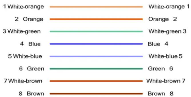
FIGURE 42 CORRESPONDING RELATIONSHIP OF A CROSS-OVER NETWORK CABLE
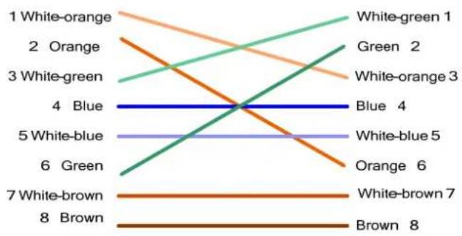
FIGURE 43 STRAIGHT-THROUGH NETWORK CABLE DIAGRAM

TABLE 7 WIRING LIST OF A STRAIGHT-THROUGH NETWORK CABLE
| Connecting End | To Where | Connect to | Remarks |
| End A | Ethernet interface of the camera | LAN | Number of cables: 1Length: as per configuration |
| End B External network device Network port |
Operating Instructions
Power-on Self-Test
After power-on, the dome camera implements the power-on self-test (POST).
Operations for Basic Functions
- Panning and tilting:
Press keys Up, Down, Left, or Right on the control keyboard of the user interface to move to the expected direction.
- Zooming:
Press the TELE key on the keyboard to pan the lens in and to zoom in the object; press the WIDE key to pan the lens out and to zoom out the object.
- Focusing:
Press the FAR key on the keyboard to make the distant object become distinct, and the object nearby become blurry. Press the NEAR key to make the object nearby become distinct, and the distant object become blurry. In automatic focusing mode, manual focusing operations are still effective. After other operations (except manual focusing operations) are implemented, the dome camera is restored to the automatic focusing position.
- Iris operations:
Press the OPEN key on the keyboard to enlarge the iris and enhance the image brightness gradually. Press the CLOSE key to narrow the iris and reduce the image brightness gradually. In auto iris mode, the OPEN and CLOSE keys are still effective. After other operations (except manual iris operations) are implemented, the dome camera restores to automatic iris mode.
- Preset operations:
i. Preset operations can be configured and controlled via the keyboard with the help of the dome menu.
ii. The dome supports 256 presets. Some preset numbers are reserved for special functions. For details, refer to section Operations for Special Functions.
iii. For preset operations via the user interface, refer to section Setting Preset Position.
iv. For preset operations via the menu, refer to section Preset.
Operations for Special Functions
Table 8 lists the dome presets with special functions.
TABLE 8 PRESETS WITH SPECIAL FUNCTIONS
| Operation Function Operation Function | ||||
| Call No. 71 preset | To implement auto scan 1 | Call No. 83 preset | To implement auto tour 3 | |
| Call No. 72 preset | To implement auto scan 2 | Call No. 84 preset | To implement auto tour 4 | |
| Call No. 73 preset | To implement auto scan 3 | Call No. 85 preset | To implement auto tour 5 | |
| Call No. 74 preset | To implement auto scan 4 | Call No. 86 preset | To implement auto tour 6 | |
| Call No. 75 preset | To implement pattern scan 1 | Call No. 87 preset | To implement auto tour 7 | |
| Call No. 76 preset | To implement pattern scan 2 | Call No. 88 preset | To implement auto tour 8 | |
| Call No. 77 preset | To implement pattern scan 3 | Save No. 92 preset | To set the left limit of auto scan 1 | |
| Call No. 78 preset | To implement pattern scan 4 | Save No. 93 preset | To set the right limit of auto scan 1 | |
| Call No. 79 preset | To open wiper | Call No. 95 preset | To enter main menu | |
| Call No. 80 preset | To close wiper | Call No. 96 preset | To stop auto scan 1 | |
| Call No. 81 preset | To implement auto tour 1 | Call No. 99 preset | To implement auto scan 1 | |
| Call No. 82 preset | To implement auto tour 2 | |||
If the dome is not configured with auto scan 1, you can call No.99 preset, and the dome camera implements 360° auto scan.
Character Prompts on the Screen
The dome camera provides abundant screen prompts for easy viewing and operation. Information to be displayed includes the Coordinate (orientation and angle), Zoom Speed, Temperature, Date/time/weekday, Alarm, Dome Title, Preset Title, Zonetips, Pattern and Auto Scan.
Coordinate: display format: [Y by Y XXX/XX], where Y indicates the direction, X indicates the horizontal and vertical angles. For example, north by west 344/-44 indicates north by west, the horizontal angle is 344° and the vertical angle is -44° .
Zoom Speed: display format: [YYX], where YY indicates the current dome zoom speed, and X indicates the prompts for the zoom speed.
Temperature: display format: [XXX/YYYY°C], where XXX is the dome top temperature, YYY is the dome bottom temperature, and °C stands for the temperature (unit: centigrade).
Date/ Time/ weekday: display format: [2012-01-09 Tues 01:04:37], where 2012-01-09 stands for Jan. 9, 2012, 01:04:37 stands for the time in 24-hour time format.
Dome Title: displays the dome title on the top of the screen with a maximum of 20 letters.
Preset Title: displays the preset title on the top of the screen with a maximum of 20 letters. After a preset is saved or deleted, a prompt such as "Preset Saved" or "Preset Deleted" will display on the screen, which disappears automatically after two seconds.
Zonetips/ Pattern/ Auto Scan: displays the configured zone tips, pattern, and auto scan title on the specified place of the screen with a maximum of 20 letters.
Configuration and Operation
Configuration Flow
The configuration flow is as shown in Figure 44.
FIGURE 44 CONFIGURATION FLOW OF THE DOME
![graph TD A["Install HD IR IP high-speed Dome"] --> B["Log in to WEB"] B --> C["Set IP Address and Port"] C --> D["Restart HD IR IP high-speed Dome"] D --> E["Log in to WEB"] E --> F["Set up Manage Host"] F --> G["Set up device ID"] G --> H["Viewing Video"] G --> I["Querying video"] I --> J["System u…](/content/2026/05/1082591/images/b32f180d8b4dda426a42e87892b36bab96be3aea4500560e6449d803715c8c98.jpg)
Login
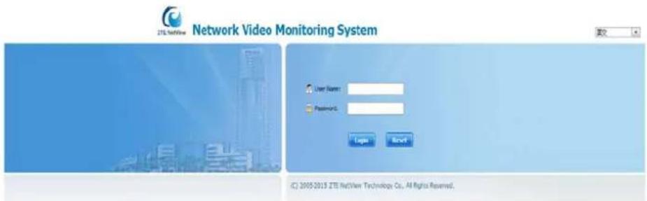
Enter the IP address of the ZNNC MP-R188W-95-NC1T-B dome in the address bar of Internet Explorer to go to the login interface. The default IP address is 192.168.1.2. You will be prompted to install a control upon initial login, as shown in Figure 45. Click OK to install the control.
FIGURE 45 PROMPT FOR INITIAL LOGIN OF WEB PAGE

After the installation, enter the User Name and Password (default user name: admin; password: 12345) in the login interface, as shown in Figure 46.
FIGURE 46 WEB LOGIN INTERFACE
Configuring Network Parameters
IP Address Setting
There are two methods of setting the IP address and port number of the camera device in the LAN.
Setting on the Web
To set the IP address or port number, perform the following steps:
-
Log in to the device, choose Config > Network Parameter > IP/Port to go to the IP/Port window, as shown in Figure 47.
-
Set IP Address, Subnet Mask, Gateway, Preferred DNS, Control Port, SIP Port Number, MAC Address and other information.

Note:
After setting the IP address and port, you will be prompted that the device will restart automatically. Click OK to restart the device. Otherwise, the setting of the IP address and port will not take effect.
FIGURE 47 IP/PORT SETTINGS

Setting with Telnet
To set the IP address of the ZNNC MP-R188W-95-NC1T-B dome by using telnet, perform the following steps:
- Click Start > Run at the bottom left of your computer to open the Run window, as shown in Figure 48. Type cmd in Open, and click OK or press ENTER.
FIGURE 48 RUN WINDOW

- Type the telnet IP address of the camera, as shown in Figure 49.
FIGURE 49 TELNET IP ADDRESS
![C:\WINDOWS\system32\cmd.exe Microsoft Windows XP [Version 5.1.2608] (C:) Copyright 1985-2001 Microsoft Corp. C:\Documents and Settings\ste\telset 192.168.60.135_](/content/2026/05/1082591/images/7ae7bd3d26f22559d35071cd6799bc7bf6705c011c96d540ee1cbcabb627e1bb.jpg)
- Type debugger to log in, and then you can see "Password:". The password is empty. Press ENTER, as shown in Figure 50. Type ? to view the help information, as shown in Figure 51.
FIGURE 50 LOGIN INTERFACE

FIGURE 51 HELP INFORMATION
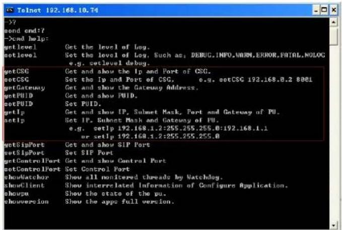
- Type set IP to set the IP address of the device.
Type set CSG, set Gateway, and set PUID to set the server parameter, gateway, and encoder ID.
PPPOE Dialup Setting
To set the PPPOE dialup, perform the following steps:
-
Choose Config > Network Parameter > PPPOE Dialup to go to the PPPOE Dialup window, as shown in Figure 52.
-
Select Start PPPOE, and type the ADSL user name and password.
3. Click Save to save the setting.

Note:
Please make sure that the ADSL network is connected to before setting PPPOE. After setting the PPPOE dialup parameters, you must restart the camera.
FIGURE 52 PPPOE DIALUP SETTING

Logging in to or Restarting the Camera
- Right-click the device address of the camera in the left Device List, and select Log in to log in to the device, as shown in Figure 53.
FIGURE 53 LOG IN

- Right-click the device address of the camera in the left Device List, and select Restart to restart the device, as shown in Figure 54.
FIGURE 54 RESTART

Setting the Access Server IP Address
- Choose Config > Network Parameter > Access Server IP to go to the Access Server IP window, as shown in Figure 55;
- The IP address and port of the registered host are those of the access server.
- Type Registered Host and Registered Port. Other parameters are generated automatically.
FIGURE 55 ACCESS SERVER IP SETTING

Setting the Device ID
To configure the basic information, perform the following steps:
- Choose Config > Basic Parameter > Basic Information, as shown in Figure 56.
- Type Device Name and Device ID.
FIGURE 56 BASIC INFORMATION CONFIGURATION INTERFACE

Configuring I/O Parameters
Function: View the DI port state, set DO parameters and test whether DO output is normal or not.
To configure I/O parameters, perform the following steps:
- Choose Config > Basic Parameter > I / O Parameter to go to the I / O Parameter window, as shown in Figure 57.
- Set the DO output time: Select DO and the time.
- Test the DO output button: Change the DO state. Then click Test to view the DO state and check whether DO output is normal or not.
- Click Save to save the settings.
FIGURE 57 I/O PARAMETER CONFIGURATION WINDOW

Setting Channel Parameters
Viewing a Video
- Click Video Preview on the menu bar to switch to the Video Preview window. Double-click your desired camera channel number to view the video, as shown in Figure 58.
FIGURE 58 VIDEO PREVIEW

- PTZ control buttons and functions are as shown in Figure 59.
FIGURE 59 PTZ CONTROL TOOL

- The video parameter setting tool is as shown in Figure 60.
FIGURE 60 VIDEO PARAMETER SETTING TOOL
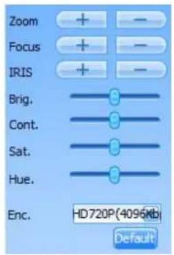

Note:
Picture control operations works only in the currently playing video window.
Video Query
To search a video, perform the following steps:
- Click the File Playback menu to switch to the File Playback window, as shown in Figure 61.
FIGURE 61 FILE PLAYBACK
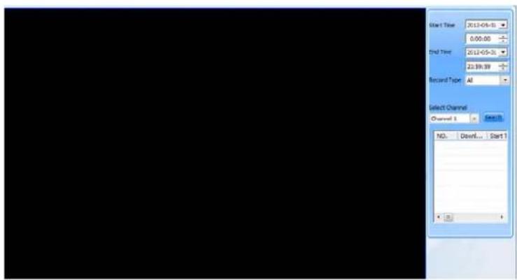
- Select Start Time and Record Type, and click Search. The Query recorded file window appears, as shown in Figure 62.
FIGURE 62 QUERY RECORDED FILES

- Double-click your desired video file from the list to view the video. Click quick launch buttons at the bottom of the window to play, pause, stop, fast reverse, or fast forward, as shown in Figure 63.
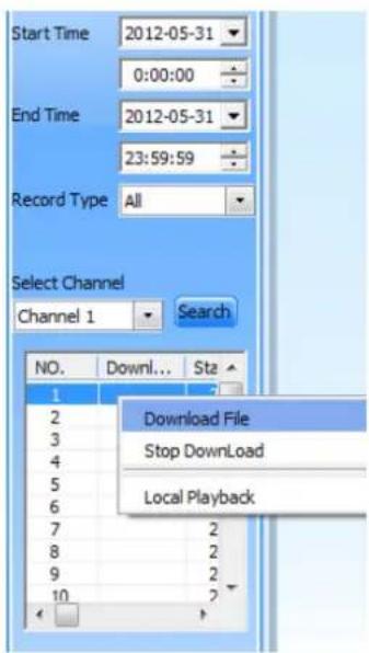
- As shown in Figure 64, right-click your desired video file from the list, select Download File, and set the save path to start downloading the file.
FIGURE 64 DOWNLOAD FILE
Setting Preset Positions
Function: Set the positions that you wish to be preset points. You can turn the camera to these preset points quickly.
- Log in to the device, click Preview, and double-click the camera that you want to view from the left pane. The video playback window appears, as shown in Figure 65. Use buttons to turn camera to the position that you want to set as a preset position.
- Click ☐ at the bottom right corner of the window to add a preset position. Click the Save button to save the setting, as shown in Figure 66.
FIGURE 66 ADD A PRESET POSITION

-
Preset positions are listed in the Preset list at the bottom right corner of the window, as shown in Figure 67. Select a preset, and click to turn the camera to the preset position.
-
Select a preset, and click if you wish to delete it.
FIGURE 67 SELECT A PRESET POSITION

Preset operations can also be performed in the dome menu. For specific operation methods, please refer to section Preset.
Setting Encoding Parameters
Function: Set encoding parameters of each video channel according to the network environment to obtain the best video effect.
To set encoding parameters, perform the following steps:
- Choose Config > Channel Parameter > Encoding Parameter to go to the Encoding Parameter window, as shown in Figure 68.
- Click Read to see current parameters.
- Select Video Channel and set the video format and resolution.
- Click Save to save the settings.

Note:
Setting the video resolution will restart the device automatically to put it into effect.
FIGURE 68 ENCODING PARAMETERS

Setting OSD Parameters
Function: Select whether to display user-defined information and time on the video screen. In addition, four OSD texts can be customized.
To set OSD parameters, perform the following steps:
-
Choose Config > Channel Parameter > OSD Parameter to go to the OSD Parameter window, as shown in Figure 69.
-
Click Read to see current parameters.
- Select Video Channel, and set the items that you want to display and their display positions.
- Click Save to save the settings. The OSD you set is displayed as shown in Figure 70.
FIGURE 69 SETTING OSD PARAMETERS

FIGURE 70 OSD DISPLAYED

Setting Titles
Function: You can set the dome title, preset title, regional title, pattern scan title, and auto scan title according to your application requirements. Only one item can be set in the dome title; 256 (1-256) items can be set in the preset title; 8 items (1-8) can be set in the regional title; 4 items (1-4) can be set both in the pattern scan and auto scan titles.
To set the titles, perform the following steps (adding the preset title is an example):
- Choose Config > Channel Parameter > Title Parameter to go to the Title Parameter window, as shown in Figure 71.
- Click the Add button in the option bar of Preset Title. Select the number and type the title name. Then click Set to finish setting the preset title, as shown in Figure 72.
- Please refer to the setting methods of preset titles when setting other title parameters.
- Click Read to see current parameters. The preset title setting is as shown in Figure 72. The preset title you set is displayed as shown in Figure 73.
FIGURE 71 TITLE PARAMETER WINDOW
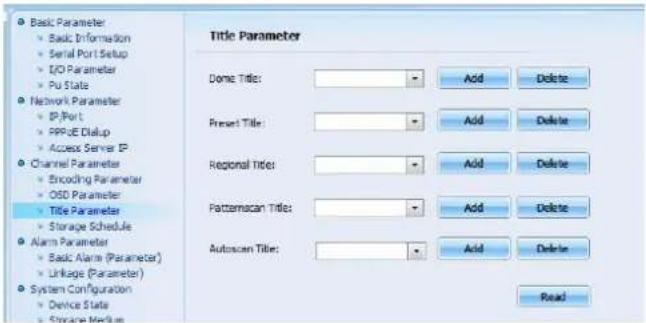
FIGURE 72 SETTING A PRESET TITLE

FIGURE 73 PRESET TITLE DISPLAYED


Note:
The title information can be displayed on the video screen only when the display information is correctly configured using the parameter configuration option on the dome menu. Please refer to section Display for the configuration method.
Setting a Storage Schedule
Function: To define a storage schedule.
To set a storage schedule, perform the following steps:
-
Choose Config > Channel Parameter > Storage Schedule to go to the Storage Schedule setting window, as shown in Figure 74.
-
Click Read to see current parameters.
-
Select Loop Record. The earliest video data will be replaced by the newest one after the storage medium is full. If it is not selected, then recording will stop when the storage medium is full.
-
If All Day Storage is selected in Storage Type, select a day from the dropdown list of Week and then select 24hrs Record.
-
There are three setting modes for storage by time segments, as follows:
Timing Record: Select a Day, select Timing Record in the Record Type dropdown list, and specify recording time.
Motion Detection: Select a Day, select Motion Detection in the Record Type dropdown list, and specify recording time.
Trigger by Alarm: Select a Day, select Trigger by Alarm in the Record Type dropdown list, and specify recording time.
-
Select a day from the Copy this schedule to field to copy the schedule to other days.
-
Select a channel from the Copy To field to copy the schedule to other channels.
-
Click Save to save the settings.
FIGURE 74 STORAGE SCHEDULE

Setting Alarm Parameters
Please log in to the device before setting alarm parameters.
Basic Alarm Parameters
Function: To set alarm parameters, and enable the audio alarm. A sound will be heard when this type of alarms occurs.
To set the basic alarm parameters, perform the following steps:
- Choose Config > Alarm Parameter > Basic Alarm (Parameter) to go to the Basic Alarm (Parameter) window.
- Set corresponding parameters.
- Click Save to save the settings, as shown in Figure 75.
FIGURE 75 BASIC ALARM PARAMETERS

Setting DI Linkage Parameters
This is to set the state of DI (Digital Input) for giving an alarm. When DI input reaches this state, DO (Digital Output) output, video recording and picture snapshot will be triggered.
- Choose Config > Alarm Parameter > Linkage (Parameter) to go to the Alarm Linkage Parameter window, as shown in Figure 76.
- Select a DI channel, and click Read to see the current state.
- Select Link This Channel and State when alarm occurs from the dropdown list. Then select the DO channel, recording and snapshot channel to be linked. Drag your mouse to set the arming time. The blue grids indicate the arming time. Select an item from the Copy To drop-down list to copy the settings of this channel to other channels. Click Save to save the settings.
FIGURE 76 DI LINKAGE PARAMETERS

System Configuration
Before system configuration, please log in to the camera.
Checking Device State
Function: The system automatically checks the communication link, monitoring service, connection with upper network management and other information of the ZNNC MP-R188W-95-NC1T-B dome.
To check the device state, perform the following steps:
- Choose Config > System Configuration > Device State to go to the Device State window, as shown in Figure 77.
FIGURE 77 DEVICE STATE
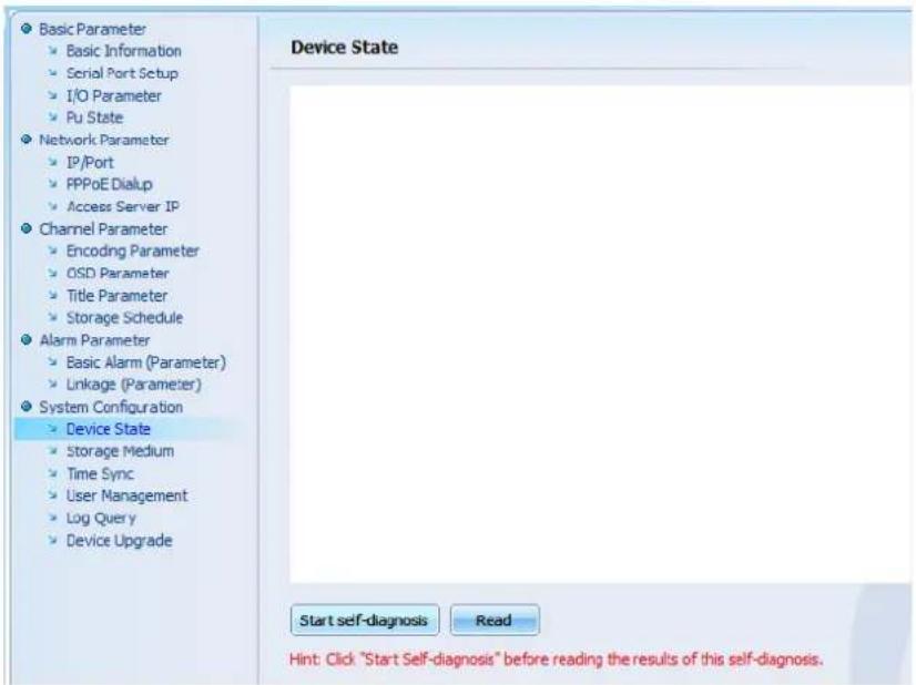
- Click Start self-diagnosis to start self diagnosis. If it succeeds, a message box appears, as shown in Figure 78.
FIGURE 78 SUCCESS MESSAGE

- Click Read. Self-diagnosis results are displayed, as shown in Figure 79.
FIGURE 79 SELF-DIAGNOSIS RESULTS

Storage Medium Management
Function: Check the storage medium information, including the medium type, total capacity, free space, state, and format state.
Select Disk and number, and click Format to format the selected storage medium, as shown in Figure 80.
FIGURE 80 STORAGE MEDIUM

Time Synchronization
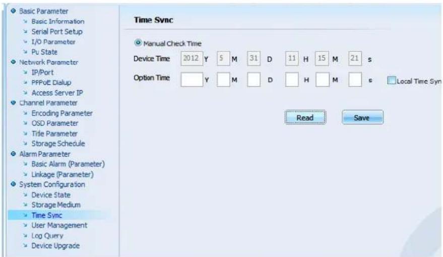
Function: Set the clock time of the ZNNC MP-R188W-95-NC1T-B dome. To set the clock time, perform the following steps:
- Choose Config > System Configuration > Time Sync to go to the Time Sync window, as shown in Figure 81.
- Click Read to see the current clock time information. Set the new time and click Save to update the clock information.
FIGURE 81 TIME SYNC
User Management
Function: Add, modify and/or delete users and set the authority for users. When logging in by Web, you need to type the user name and password.
Choose Config > System Configuration > User Management to go to the User Management window, as shown in Figure 82.
FIGURE 82 USER MANAGEMENT

1. Adding a user
Click Add to go to the User Info window, as shown in Figure 83. Type User Name, Password, and Confirm Password. Click OK to save the user information.
FIGURE 83 ADD A USER

2. Setting user permissions
Choose the user to be granted with permissions, as shown in Figure 84. Select the items in the Permit column to add user permission. Click Save to save the parameters.
FIGURE 84 SET USER PERMISSION

3. Modifying a user password
Choose a user and click Modify to go to the User Info window, as shown in Figure 85. Type Old Password, Password, and Confirm Password. Click OK to save the modification.
FIGURE 85 MODIFY A USER PASSWORD

Log Query
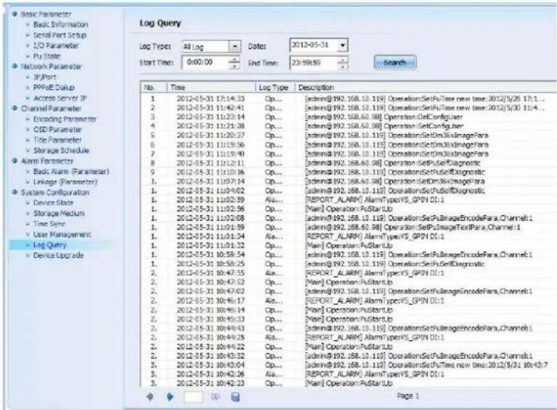
Function: Query operation, alarm, and error log information in the specified time range.
To query a log, perform the following steps:
-
Choose Config > System Configuration > Log Query to go to the Log Query window, as shown in Figure 86.
-
Select Log Type, Date, Start Time and End Time. Then click Search. The query results are as shown in Figure 87.
FIGURE 86 LOG QUERY

FIGURE 87 LOG QUERY RESULT
Device Upgrade
To upgrade the device software, perform the following steps:
- Select the camera device to be upgraded from the Device List at the left. Choose Config > System Configuration > Device Upgrade to go to the Device Upgrade window, as shown in Figure 88.
- Click Browse, and find the file to be upgraded in the pop-up dialog box. Click Open.
- Click Upgrade to start upgrading the device.
FIGURE 88 DEVICE UPGRADE


Note:
Upgrading will not be done successfully unless the name of the downloaded file is exactly the same as the one specified in the dialog box, including case match.
Chapter 5
Menu Operation
Menu Overview
1. Menu tree
The menu tree introduces the position and superior-subordinate relationship of the menu, as well as the menu items contained in each menu level. Through the menu tree, the operator can be acquainted with the menu content and find the menu items quickly.
2. Menu operations
Operations of the dome OSD (On Screen Display) menu commands are the same as those of part control commands of the dome, as shown in Table 9.
TABLE 9 COMMON CONTROL COMMANDS OF MENU OPERATIONS
| Control Command | Function |
| Call No. 95 preset | Open the dome menu |
| Return to previous menu/ exit the edit without saving/cancellation | |
| Enter the submenu/exit the edit and save the setting/confirmation | |
| <(joystick) Up> | Move the cursor up or add the value |
| Move the cursor down or decrease the value | |
| Move the cursor left in edit status | |
| Move the cursor right in edit status |
3. Attributes of the menu item
TABLE 10 ATTRIBUTES OF MENU ITEMS
| Menu Item Postfix | Description |
| [->] Indicates the sub-menu | |
| [:] Indicates editable status | |
| Unsigned | Indicates the execution of a certain function |

Note:
■ [N/A] means that the menu item is unchangeable in current mode.
- [#] indicates a space.
Password Screen
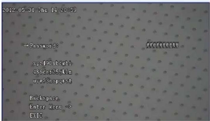
If the menu password protection is disabled, you can call the NO. 95 preset to display the main menu screen directly. When the menu password protection is enabled, the setup screen is displayed, as shown in Figure 89.
FIGURE 89 PASSWORD SETUP SCREEN
1. Password
i. The dome password can be classified into two kinds: user password and super user password.
A user password is 6-digit and the factory default is "000000". The user can change the password. For detailed operations, refer to section Password.
A super user password is 10-digit and generated by the SN (Serial Number) of the dome core, which can not be changed. It is not open to normal users. If the user forgets the user password, he/she can apply for a superuser password to the manufacturer through the SN of the dome core. The user can display the menu using the
superuser password to change the 6-digit user password. Then the user can display the menu in the future with the new password.
ii. Method to enter a password:
Move the cursor to Password. Press Iris + to move the cursor to the password character selection area. The first character [x] starts to blink. Select the character by operating the joystick up, down, left, or right. The selected character blinks. Press Iris + to confirm. The [#] on the right of the Password will be replaced by [*] successively. After entering the password, press Iris - to exit.
- Password character selection area
xyz190abcghi
486def25jklm
uvw73nopqrst
The password character selection area consists of 26 lower-case letters (a-z) and 10 numbers (0-9).
- Back Space
If the entered password is incorrect, press Iris - to exit the password character selection area. Operate the joystick to move the cursor to BackSpace. Press Iris + to delete the wrong character. You can only delete characters one by one.
- Menu
After entering the password, move the cursor to Menu, and press Iris + to display the main menu. If the password is incorrect, the message "Tip: Password Wrong" is displayed below Password, prompting for retrying. If the password is correct, the main menu screen is displayed.
- EXIT
Move the cursor to EXIT, and then press Iris + to exit the menu.
Main Menu
The main menu screen is as shown in Figure 90.
FIGURE 90 MAIN MENU SCREEN

- Language - > language selection for the dome camera
- Configuration - > configuration for the dome
- CameraBasic -> Camera basic functions setup
- CameraAdvanced -> Camera advanced functions setup
- MaskZone -> MaskZone setup
- IntegratedPTZ -> Integrated PTZ (Pan Tilt Zoom) setup
- Auxiliary -> Wiper, Restore default
- Restart - > Restart the dome
- EXIT -> Exit the menu
The following introduces sub-menus of the main menu.
Configuration
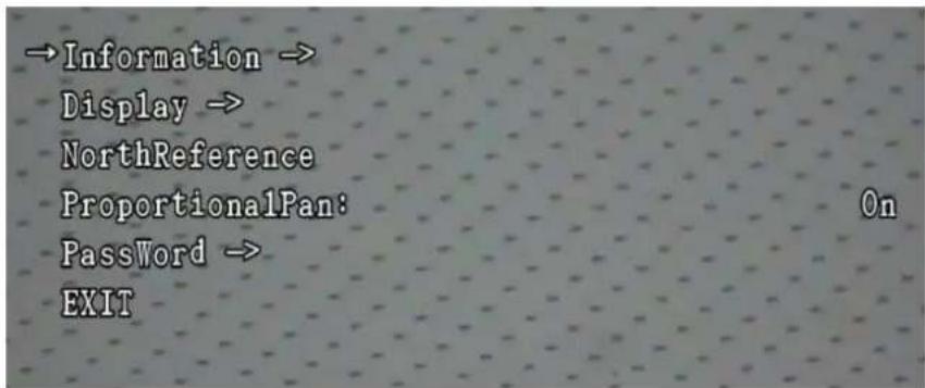
Move the cursor to Configuration. Press Iris + to display the Configuration setup screen, as shown in Figure 91.
FIGURE 91 CONFIGURATION SETUP SCREEN
Information
Move the cursor to Information. Press Iris + to enter the Information setup screen, as shown in Figure 92.
FIGURE 92 INFORMATION SETUP SCREEN

- Model: Dome camera model.
- Software Version: Software version of the microcontroller.
- Temp.: Dome bottom temperature.
- EXIT: Exit the menu.

Note:
The model information may be different due to a different built-in integrated camera.
Display
Move the cursor to Display. Press Iris + to display the Display setup screen, as shown in Figure 93.
FIGURE 93 DISPLAY SETUP SCREEN

1. Global Set
When GlobalSet is modified, other display configuration items also change synchronously, which improves the modification efficiency.
■ Display modes of GlobalSet include: Off, On and delay off
■ Off: Disable the display all the time (the default setting);
- On: Enable the display all the time;
- Delay off: Enable auto off after the preset period. The period can be set to 3sec, 5sec, 10sec, 15sec, 30sec, 1min, 3min, 5min, 10min, 15min, and 30min.

Note:
If GlobalSet is set to delay off mode, Pattern and AutoScan will not change synchronously, for example, when set GlobalSet as turning off after 30 minutes of delay, Pattern and AutoScan will always On instead of turning off after 30 minutes.
- Dome
It is used to set the Dome display mode. The display modes are the same as those of GlobalSet. - Preset
It is used to set the Preset display mode. The display modes are the same as those of GlobalSet. - Zone
It is used to set the Zone display mode. The display modes are the same as those of GlobalSet. - Zoom
It is used to set the Zoom display mode. The display modes are the same as those of GlobalSet.
6. Pattern
It is used to set the Pattern display mode. Value: Off (the default setting); On.
7. Auto Scan
It is used to set the AutoScan display mode. Value: Off (the default setting); On.
8. Coordinate
It is used to set the Coordinate display mode. The display modes are the same as those of GlobalSet.
9. Temp.
It is used to set the Temp display mode. Value: Off (the default setting); On; delay off; Auto. If this parameter is set to Auto, the temperature is displayed only when the dome internal temperature is below 0° C or above 65° C.
10. EXIT
Exit the menu.
North Reference
The dome can rotate continuously 360° in horizontally. It is marked with 0° to 359° . Select a specific angle as the Northreference direction. The angle can point to an important target or a reference benchmark with recognition significance. Save this benchmark as 0° , and other angles are represented on the basis of this benchmark.
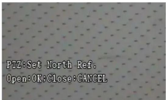
Operate the joystick up or down to move the cursor to NorthReference. Press Iris + to display the NorthReference setup screen. Move the dome via the joystick to select an appropriate northreference point. Press Iris + to save the setup and exit to the previous menu, as shown in Figure 94.
FIGURE 94 SETTING NORTH REFERENCE
Proportional Pan
The dome adjusts the rotation speed automatically according to the zoom speed, to stabilize the image for observation.
Operate the joystick up or down to move the cursor to ProportionalPan. Press Iris + to display the Proportional Pan setup screen. There are two options: On and Off. On is to enable the proportional pan, and Off is to disable it. Press iris + to save the setup and exit to the previous menu. On is the default setting.
Password
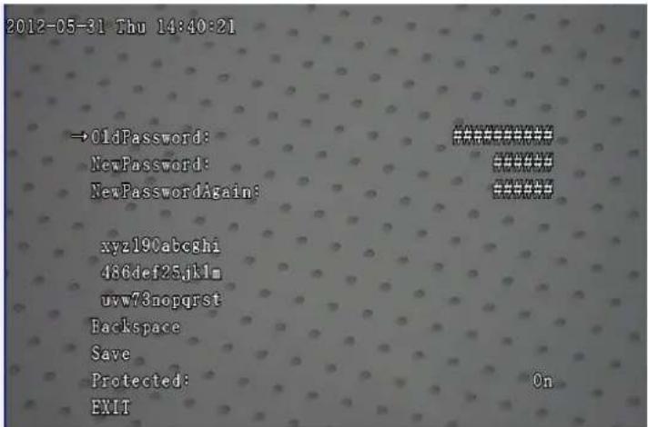
Operate the joystick up or down to move the cursor to Password. Press Iris + to display the Password setup screen, as shown in Figure 95.
FIGURE 95 PASSWORD SETUP SCREEN
1. Old Password
Move the cursor to Old Password. Press Iris + to display the password character selection area. The first character [x] starts to blink. Select the character by operating the joystick up, down, left, or right. The selected character blinks. Press Iris + to confirm. The [#] on the right of the Password will be replaced by [*] successively. After entering the password, press Iris - to exit. The default is "000000".
2. New Password
Enter the new password. Operations are the same as those for Old Password.
3. New Password Again
Enter the new password again.
4. Password character selection area
xyz190abcghi
486def25jklm
uvw73nopqrst
The password character selection area consists of 26 lower-case letters (a-z) and 10 numerals (0-9).
5. Back Space
Operate the joystick to move the cursor to BackSpace. Press Iris + to delete the wrong character. You can only delete characters one by one.
To delete OldPassword, NewPassword and New Password Again, Move the cursor to the corresponding menu item. Press Iris + to display the menu and Iris - to exit. Move the cursor to BackSpace with the joystick. Then press Iris + to delete the password of the corresponding menu item.
6. Save
Move the cursor to Save. Press Iris + to save the current setup. A new password will take effect only after being saved. If the old password is wrong, the message "Tip: Old Password Wrong" is displayed below NewPasswordAgain. Re-enter the old password. If the old password is correct and the new password is wrong, the message "Tip: New Password Wrong" is displayed on the screen. Enter the new password again.
7. Protected
It is used to enable the protection of the menu password. If it is set as Off, call No. 95 preset to enter the main menu screen as shown in Figure 90 directly. If it is set as On, call No. 95 preset to enter the password setup screen as shown in Figure 89. The factory default setting is Off.
8. EXIT
Exit the menu.
Camera Basic Parameters
Basic Parameters of the "-B" Model
Operate the joystick up or down to move the cursor to CameraBasic. Press Iris + to display the CameraBasic setup screen, as shown in Figure 96.
FIGURE 96 CAMERABASIC SETUP SCREEN
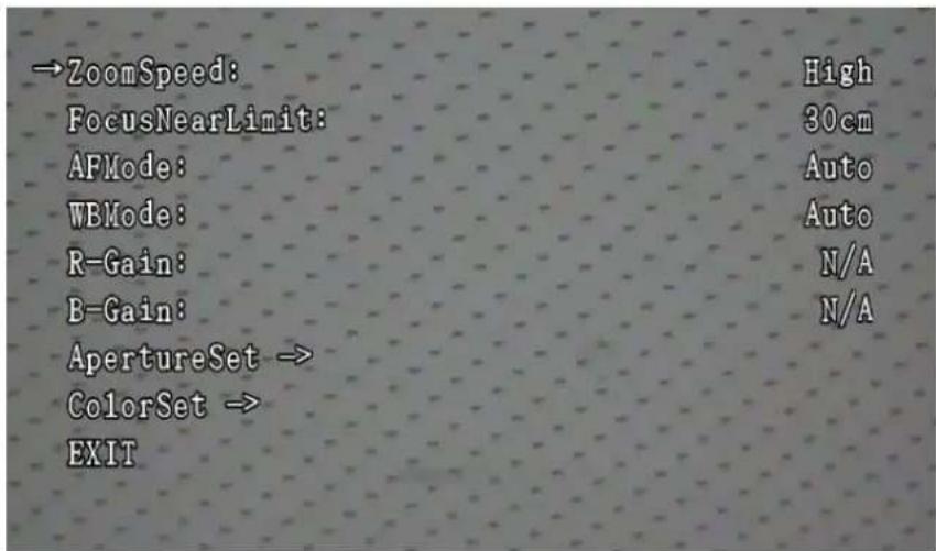
1. Zoom Speed
Operate the joystick up or down to move the cursor to ZoomSpeed. Press Iris + to display the Zoom Speed setup screen. It has two options: high (high speed) and low (low speed). Press Iris + to save the setup and exit. The default setting is High.
2. Focus Near Limit
Operate the joystick up or down to move the cursor to Focus Near Limit. Press Iris + to display the Focus Near Limit setup screen. It has four options: 1cm, 10cm, 30cm, and 100cm. An object cannot be brought into focus if it is nearer than 1cm to the camera, and will focus on all objects which are farther away than 1cm. Press Iris + to save the setup and exit. The default setting is 30cm.
3. AF (Auto focus) Mode
Operate the joystick up or down to move the cursor to AF Mode. Press Iris + to enter the AF Mode setup screen. It has five options: Auto, A, A&B, C, and Lock. The default setting is Auto. Press Iris + to save the setup.
4. WB (White Balance) Mode
Operate the joystick up or down to move the cursor to WBMode. Press Iris + to display the WBMode setup screen.
WB Mode has four options: Auto, MercuryAuto, SodiumAuto, and Manual, in which, Auto is for auto WB Mode, MercuryAuto is for mercury lamp auto WBMode, SodiumAuto for sodium lamp auto WB Mode, and Manual for manual WB Mode.
After setting, press Iris + to save the setup. The default setting is Auto.
5. R-Gain/B-Gain
If the WBMode is set as Manual, operate the joystick up or down to move the cursor to R-Gain, and press Iris + to display the R-Gain setup screen. Set the R-Gain by operating the joystick up or down. The value range is 0-255. The default setting is 0. After setting, press
Iris + to save the setup. If the WBMode is set as other mode, the status of R-Gain is N/A. The setup method of B-Gain is the same as that for R-Gain.
6. Aperture Set
Operate the joystick up or down to move the cursor to Aperture Set. Press Iris + to display the Aperture Set screen, as shown in Figure 97. Auto and manual mode can be chosen.
FIGURE 97 APERTURE SETUP MENU
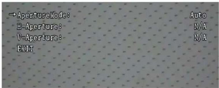
When Aperture is set as Manual, operate the joystick up or down to move the cursor to H-Aperture. Press Iris + to enter the parameter setup of horizontal aperture value. Operate the joystick up or down to choose the H-Aperture. The value range is 0-63. The default setting is 0. After setting, press Iris + to save the setup.
When Aperture is set as Auto, the value of H-Aperture cannot be modified.
The setup method of V-Aperture is the same as that of H-Aperture.
7. Color Set
Operate the joystick up or down to move the cursor to Color Set. Press Iris + to display the Color Set screen, as shown in Figure 98.
FIGURE 98 COLOR SETUP MENU

Operate the joystick up or down to move the cursor to Y-Gamma. Press Iris + to display the Y Gamma setup screen. Operate the joystick up or down to set the Y-Gamma value. The value range is 0-255, and the default is 128. After setting, press Iris + to save the setup.
Operate the joystick up or down to move the cursor to C-Gamma. Press Iris + to display the C Gamma setup screen. Operate the joystick up or down to set the C-Gamma value. The value range is 0-31, and the default is 12. After setting, press Iris + to save the setup.
Operate the joystick up or down to move the cursor to Color Level. Press Iris + to display the Color Level setup screen. Operate the joystick up or down to set the Color Level value. The value range is 0-255, and the default is 192. After setting, press Iris + to save the setup.
8. EXIT
Exit the menu.
Basic Parameters of “-A” Model
Operate the joystick up or down to move the cursor to CameraBasic. Press Iris + to display the CameraBasic setup screen, as shown in Figure 99.
FIGURE 99 CAMERABASIC SETUP SCREEN

1. Zoom Speed
Operate the joystick up or down to move the cursor to ZoomSpeed. Press Iris + to display the Zoom Speed setup screen. It has two options: High (high speed) and Low (low speed). Press Iris + to save the setup and. The default setting is High.
2. Digi Zoom Enable
Operate the joystick up or down to move the cursor to DigiZoomEnable. Press Iris + to display the DigiZoomEnable setup screen. It has two options: On (digital zoom enabled) and Off (disabled). Press Iris + to save the setup. The default setting is On.
3. Focus Near Limit
Operate the joystick up or down to move the cursor to Focus Near Limit. Press Iris + to display the Focus Near Limit setup screen. It has four options: 1cm, 10cm, 30cm, and 100cm. An object is not focusable if it is nearer than 1cm to the camera, and will focus all objects which are farther away than 1cm. The functions of other options are similar. Press Iris + to save the setup and exit. The default setting is 30cm.
4. High Sensitivity
Operate the joystick up or down to move the cursor to High Sensitivity. Press Iris + to display the High Sensitivity setup screen. It has two options: On (high sensitivity enabled) and Off (disabled). Press Iris + to save the setup. The default setting is Off.
5. WB Mode
Operate the joystick up or down to move the cursor to WBMode. Press Iris + to display the WBMode setup screen.
WBMode has eight options: Auto, Indoor, Outdoor, OutdoorAuto, ATW, SodiumAuto, SodiumFix and Manual, in which, Auto is for auto WBMode, Indoor for indoor WBMode, Outdoor for outdoor WBMode, OutdoorAuto for outdoor auto WBMode, ATW for auto tracking WBMode, SodiumAuto for sodium lamp auto WBMode, SodiumFix for sodium lamp fix WBMode, and Manual for manual WBMode.
After setting, press Iris + to save the setup and exit. The default setting is Auto.
6. R-Gain/B-Gain
If the WBMode is set as Manual, operate the joystick up or down to move the cursor to R-Gain, and press Iris + to display the R-Gain setup screen. Set the R-Gain by operating the joystick up or down. The value range is 0-255. The default setting is 0. After setting, press Iris + to save the setup. If the WBMode is set as other mode, the status of R-Gain is N/A. The setup method of B-Gain is the same as that of R-Gain.
7. Aperture
Operate the joystick up or down to move the cursor to H-Aperture. Press Iris + to display the parameter setup of horizontal aperture value. Operate the joystick up or down to set H-Aperture. The value range is 0-15. The default setting is 10. After setting, press Iris + to save the setup.
8. Color Set
Operate the joystick up or down to move the cursor to Color Set. Press Iris + to display the sub-menu of the Color Set screen, as shown in Figure 100.
9. EXIT
Exit the dome menu.
FIGURE 100 SUB-MENU OF COLOR SET
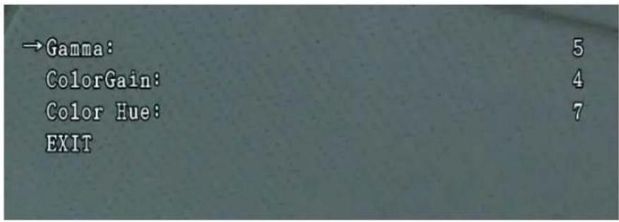
The sub-menu of Color Set includes:
Gamma
- Operate the joystick up or down to move the cursor to Color Set. Press Iris + to display the color setup screen. Move the cursor to Gamma. Operate the joystick up or down to set the Gamma value. The value range is 0-5, and the default is 5. After setting, press Iris + to save the setup.
Color Gain
- Operate the joystick up or down to move the cursor to Color Set. Press Iris + to display the color setup screen. Move the cursor to Color Gain. Operate the joystick up or down to set the Color Gain value. The value range is 0-14, and the default is 4. After setting, press Iris + to save the setup.
Color Hue
- Operate the joystick up or down to move the cursor to Color Set. Press Iris + to display the color setup screen. Move the cursor to Color Hue. Operate the joystick up or down to set the Color Hue value. The value range is 0-14, and the default is 7. After setting, press Iris + to save the setup.
EXIT
Exit the menu.
Camera Advanced
Exposure Mode of “-B” Model
Operate the joystick up or down to move the cursor to CameraAdvanced. Press Iris + to display the CameraAdvanced setup screen, as shown in Figure 101.
FIGURE 101 CAMERAADVANCED SETUP SCREEN

The functions are as follows:
- AE (Automatic Exposure) Mode
It is used to set the exposure mode. Move the cursor to AE Mode, press Iris + to display the setup screen. It has four options: Auto, Shutter, Iris, and AGC, in which, Auto is for auto exposure mode, Shutter for shutter priority mode, Iris for iris priority mode, AGC for AGC (Automatic Gain Control) priority mode. The default setting is Auto.
- Shutter
Used to set the shutter priority mode. If AE Mode is set as Shutter, the shutter speed can be manually modified. For specific settings, refer to Table 11.
- Exposure
Used to set the iris priority mode. If AE Mode is set as Iris, the value of Iris can be manually modified. For specific settings, refer to Table 11. If AE Mode is in other modes, Iris is N/A.
- AGC
Used to set the AGC priority mode. If AE Mode is AGC, the value of AGC can be modified manually. For specific settings, refer to Table 11. If Exposure is in other modes, AGC is N/A.
- DSShutter
If AE Mode is Auto, set DSShutter as Auto or Off. If AE Mode is in other modes, DSShutter is N/A. The default setting is Auto.
- WDR (Wide Dynamic Range) Mode
If AE Mode is Auto, set WDR Mode as Auto or Off. The default setting is Off. If AE Mode is in other modes, WDR Mode is N/A.
- BLC Mode
Used to set the back light compensation (BLC) mode. The default setting is Off.
8. Day/Nite Mode
Operate the joystick up or down to move the cursor to Day/Nite Mode, press Iris + to display the sub-menu setup of Day/Nite Mode, as shown in Figure 102.
9. EXIT
Exit the dome setting.
FIGURE 102 SUB-MENU OF DAY/NITE MODE

Day / Nite Mode
Operate the joystick up or down to move the cursor to Day/Nite Mode. Press Iris + to display the Day/Nite Mode setup screen. Operate the joystick up or down to set Day/Nite Mode, which can be set to Auto, Color, B&W or Timing. The default setting is Auto. After setting, press iris + to save the setup.
■ Switch At Day/Switch At Nite
When Day & Nite Mode is set as Timing, the time for switching from B&W to Color can be set. The format is 24-hour time format YY:XX, YY indicates hours, XX indicates minutes. Operate the joystick up, down, left, or right to set. After setting, press Iris + to save the setup.
The setting method for Switch At Day is the same as that of Switch At Nite.
■ ICR Sensitivity
Operate the joystick up or down to move the cursor to ICR Sensitivity. Press Iris + to display the ICR Sensitivity setup screen. Operate the joystick up or down to set ICR Sensitivity, which can be
set as High, Mid, and Low. The default setting is Mid. After setting, press Iris + to save the setup.
■ IR LED Mode
Operate the joystick up or down to move the cursor to IR LED Mode. Press Iris + to display the IR LED Mode setup screen. Operate the joystick up or down to set IR LED Mode, which can be set as Off, Smart, 10%, 20%, 30%, 40%, 50%, 60%, 70%, 80%, 90%, and 100%. The default setting is Off. After setting, press Iris + to save the setup.
■ Zoom Lens LED
Operate the joystick up or down to move the cursor to Zoom Lens LED. Press Iris + to display the Zoom Lens LED setup screen. Operate the joystick up or down to set Zoom Lens LED, which can be set as Off, On, and Auto. The default setting is Auto. After setting, press Iris + to save the setup.
- Fix Lens LED
Operate the joystick up or down to move the cursor to Fix Lens LED. Press Iris + to display the Fix Lens LED setup screen. Operate the joystick up or down to set Fix Lens LED, which can be set as Off, On, and Auto. The default setting is Auto. After setting, press Iris + to save the setup.
■ IR Percent
Operate the joystick up or down to move the cursor to IR Percent. Press Iris + to display the IR Percent setup screen. Operate the joystick up or down to set IR Percent, which can be set as Off and On. The default setting is Off. After setting, press Iris + to save the setup.
Noise Reduction
Operate the joystick up or down to move the cursor to Noise Reduction. Press Iris + to display the Noise Reduction setup screen. Operate the joystick up or down to set Noise Reduction, which can be set as ten levels: 1 ... 10. The default setting is 1. After setting, press Iris + to save the setup.
EXIT
Exit the dome setting.
TABLE 11 SHUTTER/ IRIS /AGC SETUP
| No. | Shutter(unit: s) | Iris AGC | |
| 1 1/4 F1.6 0 dB | |||
| 2 1/8 F2.3 6 dB | |||
| 3 1/15 F3.2 12 dB | |||
| 4 1/30 F4.5 18 dB | |||
| 5 1/50 F6.4 24 dB | |||
| 6 1/60 F9.1 30 dB | |||
| 7 1/100 | F12.8 -- | ||
| 8 1/120 | F18.1 -- | ||
| 9 1/180 | F25.6 -- | ||
| 10 1/250 | F36.2 -- | ||
| 11 1/500 | -- -- | ||
| 12 1/1000 | -- -- | ||
| 13 1/2000 | -- -- | ||
| 14 1/4000 | -- -- | ||
| 15 1/10000 | -- -- | ||

Note:
WDRMode and BLCMode cannot be used simultaneously. If WDRMode is On, BLCMode is set as N/A automatically; If WDRMode is Off, BLCMode can be set as On.
Exposure Mode of “-A” Model
Operate the joystick up or down to move the cursor to CameraAdvanced. Press Iris + to display the Camera Advanced setup screen, as shown in Figure 103.
FIGURE 103 CAMERA ADVANCED SETUP SCREEN
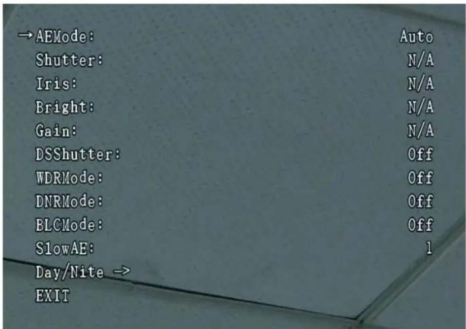
1. AE Mode
It is used to set the exposure mode. Move the cursor to AE Mode, press Iris + to display the setup screen. It has five options: Auto, Shutter, Iris, Bright and Manual, in which, Auto is for auto
exposure mode, Shutter for shutter priority mode, Iris for iris priority mode, Bright for bright priority mode, Manual for manual exposure mode. The default setting is Auto.
2. Shutter
Used to set the shutter priority mode. If AE Mode is set as Shutter or Manual, the shutter speed can be manually modified. For specific settings, refer to Table 12. If AE Mode is in other modes, Shutter is N/A.
3. Iris
Used to set the iris priority mode. If AE Mode is set as Iris or Manual, the value of Iris can be manually modified. For specific settings, refer to Table 12. If AE Mode is in other modes, Iris is N/A.
4. Bright
Used to set the brightness priority mode. If AE Mode is set as Bright or Manual, the brightness can be set. For specific settings, refer to Table 12. If AE Mode is in other modes, Bright is N/A.
5. Gain
Used to set the Gain priority mode. If AE Mode is set to Gain, the value of Gain can be modified manually. For specific settings, refer to Table 12. If AE Mode is in other modes, Gain is N/A.
6. DSShutter
If AE Mode is Auto, set DSShutter as Auto or Off. If Exposure is in other modes, DSShutter is N/A. The default setting is Auto.
7. WDR Mode
If AE Mode is Auto, set WDR Mode as Auto or Off. The default setting is Off.
8. DNR Mode
Operate the joystick up or down to move the cursor to DNR Mode, press Iris + to display the DNR Mode setup screen. Operate the joystick up or down to set DNR Mode, which can be set as 1-5 and Off. The default setting is Off. After setting, press Iris + to save the setup.
9. BLC Mode
If Exposure is Auto, set BLC Mode as On or Off. When Exposure is in other modes, BLC Mode is N/A. The default setting is Off.
10. Slow AE
Operate the joystick up or down to move the cursor to Slow AE, press Iris + to display the Slow AE setup screen. Operate the joystick up or down to set Slow AE, which has 1-48 levels. The default setting is 1. After setting, press Iris + to save the setup.
11. Day/Nite
Operate the joystick uUp or down to move the cursor to Day/ Nite, press Iris + to display the sub-menu of Day/Nite Mode, as shown in Figure 104.
12. EXIT(Move this up to after 11.)
Exit the dome setting.
FIGURE 104 SUB-MENU OF DAY/NITE MODE

Day / Nite Mode
Operate the joystick up or down to move the cursor to Day/Nite Mode. Press Iris + to display the Day/Nite Mode setup screen. Operate the joystick up or down to set Day/Nite Mode, which can be set to Auto, Color, B&W or Timing. The default setting is Auto. After setting, press Iris + to save the setup.
■ Switch At Day/Switch At Nite
When Day/ Nite Mode is set as Timing, the time switching from B&W to Color can be set. The format is 24-hour time format YY: XX, YY indicates hours, XX indicates minutes. Operate the joystick up, down, left, or right to set. After setting, press Iris + to save the setup.
The setting method of Switch At Day is the same as that of Switch At Nite.
■ ICR Sensitivity
Operate the joystick up or down to move the cursor to ICR Sensitivity. Press Iris + to display the ICR Sensitivity setup screen. Operate the joystick up or down to set ICR Sensitivity, which can be set as High, Mid, and Low. The default setting is Mid. After setting, press Iris + to save the setup.
- IR LED Mode
Operate the joystick up or down to move the cursor to IR LED Mode. Press Iris + to display the IR LED Mode setup screen. Operate the joystick up or down to set IR LED Mode, which can be set as Off, Smart, 10%, 20%, 30%, 40%, 50%, 60%, 70%, 80%, 90%, and 100%. The default setting is Off. After setting, press Iris + to save the setup.
■ Zoom Lens LED
Operate the joystick up or down to move the cursor to Zoom Lens LED. Press Iris + to display the Zoom Lens LED setup screen. Operate the joystick up or down to set Zoom Lens LED, which can be set as Off, On, and Auto. The default setting is Auto. After setting, press Iris + to save the setup.
- Fix Lens LED
Operate the joystick up or down to move the cursor to Fix Lens LED. Press Iris + to display the Fix Lens LED setup screen. Operate the joystick up or down to set Fix Lens LED, which can be set as Off, On, and Auto. The default setting is Auto. After setting, press Iris + to save the setup.
- IR Percent
Operate the joystick up or down to move the cursor to IR Percent. Press Iris + to display the IR Percent setup screen. Operate the joystick up or down to set IR Percent, which can be set as Off and On. The default setting is Off. After setting, press Iris + to save the setup.
- Noise Reduction
Operate the joystick up or down to move the cursor to Noise Reduction. Press Iris + to display the Noise Reduction setup screen. Operate the joystick up or down to set Noise Reduction, which can be set as ten levels: 1 ... 10. The default setting is 1. After setting, press Iris + to save the setup.
EXIT
Exit the dome setting.
TABLE 12 SHUTTER/IRIS/BRIGHT/GAIN SETUP
| No. | Shutter (unit: s) | Iris Bright Gain | |||
| NTSC PAL | |||||
| 1 1/10000 | 1/10000 | F1.6 F1.6 | 28dB 28dB | ||
| 2 | 1/6000 | 1/6000 | F2.0 | F1.6/26dB | 26dB |
| 3 | 1/4000 | 1/3500 | F2.4 | F1.6/24dB | 24dB |
| 4 | 1/3000 | 1/2500 | F2.8 | F1.6/22dB | 22dB |
| 5 | 1/2000 | 1/1750 | F3.4 | F1.6/20dB | 20dB |
| 6 | 1/1500 | 1/1250 | F4.0 | F1.6/18dB | 18dB |
| 7 | 1/1000 | 1/1000 | F4.8 | F1.6/16dB | 16dB |
| 8 | 1/725 | 1/600 | F5.6 | F1.6/14dB | 14dB |
| 9 | 1/500 | 1/425 | F6.8 | F1.6/12dB | 12dB |
| 10 | 1/350 | 1/300 | F8.0 | F1.6/10dB | 10dB |
| 11 | 1/250 | 1/215 | F9.6 | F1.6/8dB | 8dB |
| 12 1/1 | 80 1/150 | F11 F1.6/6dB 6dB | |||
| 13 1/1 | 25 1/120 | F14 F1.6/4dB 4dB | |||
| 14 | 1/100 | 1/100 | CLOSE | F1.6/2dB | 2dB |
| 15 | 1/90 | 1/75 | -- | F1.6/0dB | 0dB |
| 16 | 1/60 | 1/50 | -- | F2.0/0dB | -3dB |
| 17 1/30 | 1/25 -- | F2.4/0dB | -- | ||
| 18 1/15 | 1/12 -- | F2.8/0dB | -- | ||
| 19 1/8 | 1/6 -- | F3.4/0dB -- | |||
| 20 1/4 | 1/3 -- | F4.0/0dB -- | |||
| 21 1/2 | 1/2 -- | F4.8/0dB -- | |||
| 22 1/1 | 1/1 -- | F5.6/0dB -- | |||
| 23 -- | -- -- | F6.8/0dB -- | |||
| 24 -- | -- -- | F8.0/0dB -- | |||
| 25 -- | -- -- | F9.6/0dB -- | |||
| 26 -- | -- -- | F11/0dB -- | |||
| 27 -- | -- -- | F14/0dB -- | |||
| 28 -- | -- -- | CLOSE/0dB | -- | ||

Note:
WDRMode and BLCMode cannot be used simultaneously. If WDRMode is On, BLCMode is set as N/A automatically; If WDRMode is Off, BLCMode can be set as On.
Mask Zone
Mask Zone refers to the technology which generates opaque color lumps in video signals to cover images involved with personal privacy. Operate the joystick up or down to move the cursor to MaskZone. Press Iris + to display the MaskZone setup screen, as shown in Figure 105.
FIGURE 105 MASKZONE SETUP SCREEN

1. Mask Number
It refers to the privacy mask number. For the dome whose model postfix is "-A", the mask number can be from 1 to 24. The default setting is 1. Up to eight mask zones can display in one image. For the dome whose model postfix is "-B", the mask number can be from 1 to 8. The default setting is 1. Up to four mask zones can display in one image.
2. Enable
Use to enable/disable the privacy protection (mask) function. It has two options: On and Off. Set Enable as On before editing the privacy mask zones. The default setting is Off.
3. Edit Mask
Use to edit the mask zone. Set Enable as On. If the cursor points to EditMask, press Iris + to set the position and size of the mask zone. For specific settings, refer to the section Mask Zone Setup of "-B" and MaskZone Setup of "-A".
4. Delete Current
It is for deleting the current mask zone.
5. Delete All Masks
It is for deleting all mask zones.
6. EXIT
Exit the menu.
Mask Zone Setup of “-B” Model
Operate the joystick up or down to Move the cursor to EditMask. Press Iris + to display the mask region setup screen as shown in Figure 106. Locate the center point of the mask region at the image center by rotating the dome. Press Iris + to display the mask size setup screen as shown in Figure 107. Operate the joystick up, down, left, or right to adjust the size of the mask zone. After setting, press Iris + to save the setting and exit.
FIGURE 106 EDITMASK REGION SETUP SCREEN
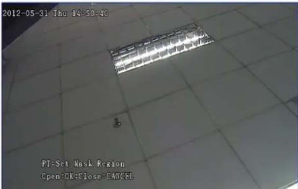
FIGURE 107 EDITMASK SIZE ADJUSTMENT SCREEN

In Figure 106, "PT: Set Mask Region" is used to select the mask region by rotating the dome horizontally and vertically via the joystick. "Open: OK; Close: CANCEL" is used to confirm the setup of the mask zone in the current position by pressing Iris +. To cancel the setting, press Iris - to return to previous menu, and the privacy protection (mask) function is disabled.
In Figure 107, "PT: Set Mask Border" is used to increase or decrease the mask size vertically by operating the joystick up or down, or to increase or decrease the mask size horizontally by operating the joystick left or right. "Open: OK; Close: CANCEL" is used to save the mask size setup by pressing Iris + . To cancel the setup, press Iris - to return to previous menu, and the privacy protection (mask) function is disabled.
MaskZone Setup of "-A" Model
Operate the joystick up or down to move the cursor to EditMask. Press Iris + to display the EditMask Region setup screen as shown in Figure 108. Locate the center point of the mask region at the image center by rotating the dome. Press Iris + to display the mask size adjustment screen as shown in Figure 109. Operate the joystick up, down, left, or right to adjust the size of the mask zone. After setup, press Iris + to save the setting and exit.
FIGURE 108 EDITMASK REGION SETUP SCREEN

FIGURE 109 EDITMASK SIZE ADJUSTMENT SCREEN
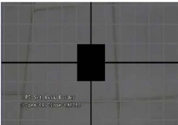
In Figure 108, "PT: Set Mask Region" is used to select the mask region by rotating the dome horizontally and vertically via the joystick. "Open: OK; Close: CANCEL" is used to confirm the setup of mask zone in the current position by pressing Iris +. To cancel the setting, press Iris - to return to the previous menu, and the privacy protection (mask) function is disabled.
In Figure 109, "PT: Set Mask Border" is used to increase or decrease the mask size vertically by operating the joystick up or down, or to increase or decrease the mask size horizontally by operating the joystick left or right. "Open: OK; Close: CANCEL" is used to save a mask size setup by pressing iris+. To cancel the setup, press Iris - to return to the previous menu, and the privacy protection (mask) function is disabled.
Integrated PTZ
Operate the joystick up or down to move the cursor to IntegratedPTZ. Press Iris + to display the IntegratedPTZ setup screen, as shown in Figure 110. Refer to the following function and operation description of the integrated PTZ.
FIGURE 110 INTEGRATEDPTZ SETUP SCREEN

Preset
Any group of data containing the horizontal coordinate, vertical coordinate, and zoom rate of the dome corresponds to a specific location within the monitoring range of the dome. This group of data is pre-stored and needed to enable quick location of the corresponding monitoring position, which is called Preset.
Operate the joystick up or down to move the cursor to Preset. Press Iris + to display the Preset setup screen, as shown in Figure 111.
FIGURE 111 PRESET SETUP SCREEN

- Preset Number
Preset number: 1 to 256 (excluding numbers from 71 to 99); the default setting is 1.
- Go to Preset
If the current number is not edited as a Preset number, the dome will keep still when this current number is called.
- Freeze Mode
Set Freeze Mode as On, the dome camera outputs static images when a preset is called. After the preset calling operation, the dome
resumes to output dynamic images. Set it as Off, the dome outputs dynamic images all the time. The default setting is Off.
3. Edit Scene
Move the cursor to EditScene, and press Iris + to display the Edit Scene setup screen, as shown in Figure 112. Select the Preset scene through PTZF operation. After the setting, press Iris + to save the setting and exit.
4. Delete Current
Use to delete the current Preset.
FIGURE 112 EDITSCENE SETUP SCREEN
5. EXIT
Exit the menu.
Tour
The combination of presets and intervals are called tour nodes. The sequence formed by several tour nodes is called a tour sequence. The process in which the dome calls tour sequences circularly is called Tour.
Operate the joystick up or down to move the cursor to Tour. Press Iris + to display the Tour setup screen, as shown in Figure 113.
FIGURE 113 TOUR SETUP SCREEN
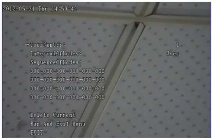
- Tour Number
Tour number: 1-8, the default setting is 1
- Interval of Nodes
Interval of tour nodes: 0 sec -255 sec, the default setting is 3sec.
- Sequence of Nodes
Use to set the tour sequence. 000 stands for the preset number (1-256, excluding 71-99). A sequence can be added with 24 preset points. The tour calls presets successively from left to right and then from up to down. If the preset 000 appears in the sequence, it will be skipped.
The method of setting the tour sequence is as below:
Operate the joystick up or down to move the cursor to Sequence of Nodes and then press Iris + to access the edit status. The first 000 flashing indicates that node can be adjusted by operating the joystick up or down to select a preset number for that node, and other nodes can be selected by operating the joystick left or right. Repeat the same operation to select a preset number. Moving to another line, move the cursor to the "-" position, and operate the joystick up or down to go to your desired line. After setting all of the nodes, press Iris + to save and exit the edit status. Press Iris - to exit the edit status without saving.
- Delete Current
Move the cursor to this menu item, and then press Iris + to delete the current tour.
- Run and Exit Menu
Move the cursor to this menu item, and then press Iris + to run the tour and exit the menu.
- EXIT
Exit the menu.
Zone Tips
Set left and right limits for the horizontal rotation directions of the dome to form a zone, and set a title for the zone. When the dome runs to the zone, the title will show the features of this zone automatically.
Operate the joystick up or down to move the cursor to Zone Tips. Press Iris + to display the Zone Tips setup screen, as shown in Figure 114.
FIGURE 114 ZONE TIPS SETUP SCREEN

- Zone Number
Zone number: 1-8, the default setting is 1.
- Left Limit
Use to set the left limit of the zonetips. Move the cursor to Left Limit and then press Iris + to display the Left Limit setup screen, as shown in Figure 115. Select the left limit by rotating the dome, and then press Iris + to save the setting and exit to the previous menu.
- Right Limit
Use to set the right limit of the zonetips. The setup method is the same as that of Left Limit.
- Delete Current
Move the cursor to the menu item and then press Iris + to delete the current zone tips.
FIGURE 115 ZONETIPS LEFT LIMIT SETUP SCREEN

5. EXIT
Exit the menu.
Pattern
The dome records the user-initiated PTZ and call-preset commands within a certain period. The function of playing back the above commands is called Pattern.
Operate the joystick up or down to move the cursor to Pattern. Press Iris + to display the Pattern setup screen, as shown in Figure 116.
FIGURE 116 PATTERN SETUP SCREEN

1. Pattern Number
Pattern number: 1-4. The default setting is 1.
2. Program
Move the cursor to Program and press Iris + to display the Program setup screen, as shown in Figure 117. Rotate the dome horizontally or vertically, perform zooming operations (zoom in/out) or call presets to complete the programming.
3. Delete Current
Move the cursor to th menu item and then press Iris + to delete the current pattern.
4. Run and Exit Menu
Move the cursor to this menu item, and then press Iris + to run the current pattern and exit the menu.
5. EXIT
Exit the menu.
FIGURE 117 PROGRAM SETUP SCREEN
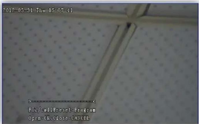
In Figure 117, "----" is the pattern scan storage progress bar (5% for each segment). "PTZ/CallPreset: Program" indicates the operation to edit the pattern through horizontal and vertical rotations, zooming operations, and calling presets. "Open: OK; Close: CANCEL" indicates that you can press Iris + to save the setup or press Iris - to exit to the previous menu without saving.
Auto Scan
AutoScan is for setting the left and right limits of the horizontal rotation directions of the dome. When this function is enabled, the dome recovers to the left position limit and then rotates to the right with the preset scan speed. After reaching the right position limit, the dome stops for one second, and then rotates to the left. After reaching the left position limit, the dome stops for one second and rotates to the right again. The dome moves back and forth until it receives the scan stop command or the left/right rotation command.
Operate the joystick up or down to move the cursor to AutoScan. Press Iris + to display the AutoScan setup screen, as shown in Figure 118.
FIGURE 118 AUTOSCAN SETUP SCREEN

- Scan Number
AutoScan number: 1-4. The default setting is 1.
- Scan Speed
Auto Scan speed: 1-255 level. If it is set to 1, the Auto Scan speed is 0.1°/sec; at 255, the AutoScan speed is 200°/sec.
- Left Limit
Used to set the AutoScan left limit. Refer to Left Limit in Zone Tips for details.
- Right Limit
Used to set the AutoScan right limit. Refer to Right Limit in Zone Tips for details.
- Delete Current
Move the cursor to this menu item and then press Iris + to delete the current AutoScan.
- Run and Exit Menu
Move the cursor to this menu item, and then press Iris + to run the current Auto Scan and exit the menu.
- EXIT
Exit the menu.

Note:
Through saving the No.92 preset, you can set the left limit of the No. 1 AutoScan. Through saving the No.93 preset, you can set the right limit of the No. 1 AutoScan. This method cannot be used to set the AutoScan of the other numbers.
Schedules
The dome can execute certain functions automatically at different times. The time points and functions can be set. Functions that can be set include: Preset, Tour, AutoScan, and Pattern.
Operate the joystick up or down to move the cursor to Schedules. Press Iris + to display the Schedules setup screen, as shown in Figure 119.
FIGURE 119 SCHEDULES SETUP SCREEN
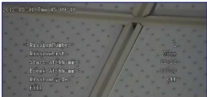
- Mission Number
Mission number: 1-32. The default setting is 1.
- Mission List
Mission list: None, Tour 1 to Tour 8, AutoScan 1 to AutoScan 4, Pattern 1 to Pattern 4 and Preset 1 to Preset 32. The default setting is None.
- Start At
Move the cursor to this menu item, and then press Iris + to display the Schedules setup screen. Operate the joystick left or right to move to hour or minute. It flickers after being operate the joystick up or down to set the start time. Press Iris + to save and exit. Press Iris - to cancel the setup and exit.
- Break At
The setup method is the same as that of Start At
If the start time and the break time are set to the same time, the settings are not available. If the start time is earlier than the break time, the camera runs as set. If the start time is later than the break time, the dome runs the set functions normally at the preset start time, and finishes at 12:00pm of the same day.
- Mission Cycle
Move the cursor to this menu item and then press Iris + to display the Mission Cycle setup screen. It has 10 options: Off, Within 24h, Once a day, Monday, Tuesday, Wednesday, Thursday, Friday, Saturday, and Sunday. The default setting is Off.
■ Off To disable the mission
■ Within 24h To execute one mission within 24 hours
■ Once a day To execute the mission once a day
■ Monday To execute the mission every Monday
■ Tuesday To execute the mission every Tuesday
...
■ Sunday To execute the mission every Sunday
- EXIT
Exit the menu.
Action When Power
After the power-on self-testing (POST), the dome can be set to execute any of the following actions: Recover (action before power-off), Preset, Tour, AutoScan and Pattern.
Operate the joystick up or down to move the cursor to Action When Power. Press Iris + to display the Action When Power setup screen, as shown in Figure 120.
FIGURE 120 ACTION WHEN POWER SETUP SCREEN
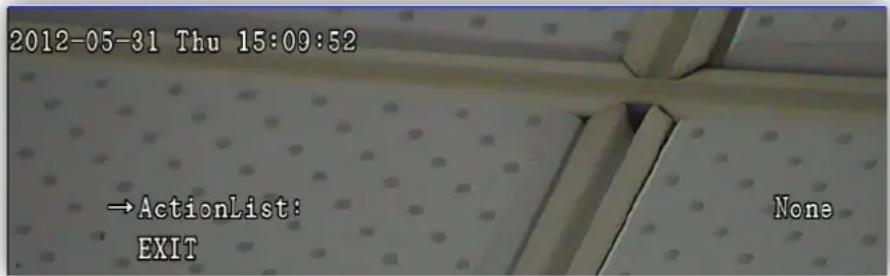
■ Action List
Used to set the ActionList for Action When Powered On: None, Recover, Tour 1- Tour 8, AutoScan 1 to AutoScan 4, Pattern 1 to Pattern 4 and Preset 1 to Preset 32. The default setting is None.
EXIT
Exit the menu.
After setting, the dome will execute Action When Power automatically 3 seconds after the POST the next time the dome is powered on.
Note:
When Action When Power is set to Recover, the dome recovers the action before power-off automatically after being powered on. If the dome is executing Tour, AutoScan or Pattern before power-off, it will continue the function after being powered on. If the dome is still before power-off, it will recover to the position before power-off after being powered on.

Action When Idle
If the dome control bus is idle for a certain period, the dome executes any of the following functions automatically: Preset, Tour, AutoScan and Pattern.
Operate the joystick up or down to move the cursor to Action When Idle. Press Iris + to display the Action When Idle setup screen, as shown in Figure 121.
FIGURE 121 ACTION WHEN IDLE SETUP SCREEN
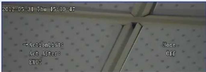
1. Action List
Used to set the Action List for Action When Idle: None, Tour 1-Tour 8, AutoScan 1 to AutoScan 4, Pattern 1 to Pattern 4 and Preset 1 to Preset 32. The default setting is None.
2. Act After
Used to set the action waiting period: Off, 3sec, 5sec, 10sec, 15sec, 30sec, 1min, 3min, 5min, 10min, 15min and 30min. The default setting is Off.
3. EXIT
Exit the menu.
Other Functions
Operate the joystick up or down to move the cursor to Other Functions. Press Iris + to display the Other Functions setup screen, as shown in Figure 122. We will introduce the functions and operations below.
FIGURE 122 SUB-MENU SCREEN OF OTHER FUNCTIONS

Wiper
Operate the joystick up or down to move the cursor to Wiper. Press Iris + to display the Wiper setup screen, as shown in Figure 123
FIGURE 123 WIPER SETUP SCREEN
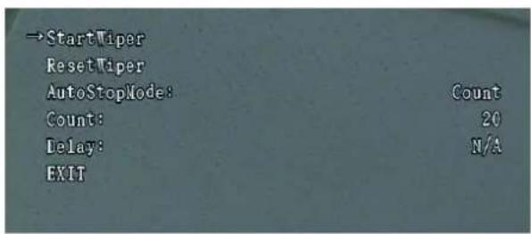
- Start Wiper
Operate the joystick up or down to move the cursor to Start Wiper. Press Iris + to start wiper.
- Reset Wiper
Operate the joystick up or down to move the cursor to Reset Wiper. Press Iris + to stop wiper.
- Auto Stop Mode
Operate the joystick up or down to move the cursor to Auto Stop Mode. Press Iris + to go to the setup item, in which Count and Delay can be set to stop wiper. The default setting is Count.
- Count
When Auto Stop Mode is set as Count, Count is in adjustable status. Operate the joystick up or down to move the cursor to Count. Press Iris + to go to the setup item, in which 1.....128 can be set, indicating that wiper stops when it reaches the set time. The default setting is 20. When Auto Stop Mode is set as Count, Delay is in N/A status, indicating that Delay cannot be adjusted.
- Delay
When Auto Stop Mode is set as Delay, Count is in adjustable status. Operate the joystick up or down to move the cursor to Delay. Press Iris + to go to the setup item, in which 1Hour, 2Hour, 5Hour, 10Hour, 15Hour, 24Hour, and 48Hour can be set, indicating that wiper stops when it reaches the set time. The default setting is 1Hour. When Auto Stop Mode is set as Delay, Count is in N/A status, indicating that Count cannot be adjusted.
- EXIT
Exit the wiper setup window.
Default
Operate the joystick up or down to move the cursor to Default. Press Iris + to display the Default setup screen, as shown in Figure 124. Refer to Appendix E: Factory Default Settings Table for the default settings of the dome.
FIGURE 124 DEFAULT SETUP SCREEN
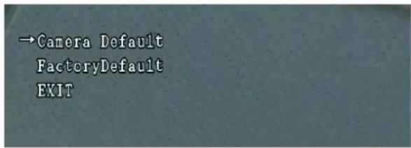
1. Camera Default
Used to restore the camera module to the default settings. With this option, parameters related to the camera module will be restored to factory default, with other irrelative parameters unchanged.
2. Factory Default
Used to restore the dome to factory default settings. All parameters of the dome will be restored to the factory default state.
3. EXIT
Exit the default setup window.
Restart
Operate the joystick up or down to move the cursor to Restart. Press Iris + to restart the ZNNC MP-R188W-95-NC1T-B camera.
Exit
Exit the menu.
Appendix A
Terms and Abbreviations
Terminology
- Screen Menu
The dome is equipped with English menus through which the user can set functions of the dome. Open the menu by saving or calling the No. 95 Preset. Exit by pressing EXIT in the menu.
- Auto Scan
AutoScan is for setting the left and right limits of the horizontal rotation directions of the dome. After the function is enabled, the dome recovers to the left position limit and then rotates to the right with the preset scan speed. After reaching the right position limit, the dome stops for one second, and then rotates to the left. After reaching the left position limit, the dome stops for one second and rotates to the right again. The dome moves back and forth until it receives the scan stop command or the left/right rotation command.
- Auto flip
The dome rotates vertically downward to the 90° position and maintains for about 1 second. It then rotates horizontally 180° . In the flip status, it sends commands for rotating vertically downward. The dome lifts up. The dome terminates the flip once receiving the stop command.
- Proportional Pan
According to the zoom rate, the dome automatically regulates the rotation speed to achieve a stabilized view.
- Iris adjustment
The adjustment of the iris has two modes: Auto and Manual. Turn on the iris, and the image is brightened. Turn off the iris, and the image is darkened. If Iris is set to Auto, the dome will recover to the auto mode once receiving the up/down/left/right rotation command.
- Preset
Any group of data containing the horizontal coordinate, vertical coordinate, and zoom rate of the dome correspondsto a specific location within the monitoring range of the dome. This group of data
is pre-stored and called as needed to locate the corresponding monitoring position, which is called a Preset.
7. Tour
The combination of preset and interval is called tour mode. The sequence formed by several tour modes is called tour sequence. The process in which the dome calls a tour sequence circularly is called Tour.
8. Pattern
The dome records the user-initiated PTZ and call-preset commands within a certain period. The function of playing back the above commands is called Pattern.
9. Zone tips
Set left and right limits of the horizontal rotation directions of the dome to form a zone, and give the zone a name. When the dome runs to the zone again, the title will automatically display the features of this zone.
10. Mask Zone
Mask Zone refers to the technology which generates opaque color lumps in video signals to mask images involved with personal privacy.
11. North Reference
The dome can rotate continuously 360° horizontally. It is marked with 0° to 359° . Select a specific angle as the North reference direction. The angle can point to an important target or a reference benchmark with recognition significance. Save this benchmark as 0° , and other angles will be represented on the basis of this benchmark.
12. Password
The dome has password protection which can be enabled or disabled. If the password protection function is enabled, you must enter the password each time when accessing the menu. There are two kinds of password: user password and superuser password. The superuser password is a 10-digit number string generated by the SN. of the dome core. It is unique and cannot be changed. The user password is a 6-digit number string which can be set by the users. The superuser password is generally not available to the users. If a user forgets the user password, he/she can apply for a superuser password from the manufacturer.
13. Schedules
The dome can execute a function automatically at different times. The times and the functions can be set. Functions that can be set include: Preset, Tour, AutoScan, and Pattern.
14. Action When Idle
If the dome control bus is idle for a certain period, the dome executes any of the following functions automatically: Preset, Tour, AutoScan and Pattern.
15. Action When Power
After the POST, the dome can be set to execute any of the following actions: Recover (action before power-off), Preset, Tour, AutoScan and Pattern.
16. Backlight Compensation
If the backlight of the image is relatively bright due to level suppression, the foreground is normally darker. The technology which enhances the whole brightness of the image to brighten the foreground is called backlight compensation.
17. Wide dynamic
If the monitoring region contains a bright and a dark area simultaneously, capture images in two brightnesses at two different shutter speeds, then combine the two images into one frame image, so that the brightest and darkest parts in the scene can both be viewed distinctly.
18. Slow AE
The SlowAE function can slow the variation of the exposure level so as to facilitate tracing and reproducing the image of a mobile object with sudden illumination changes.
19. DNR Mode
When the monitoring region has great noise, enable the DNR Mode to denoise the image to achieve a better image.
Abbreviations
TABLE 13 ABBREVIATIONS
| Abbreviations Full Name | |
| PT Pan Tilt | |
| PTZ Pan Tilt Zoom | |
| PTZF Pan Tilt Zoom Focus | |
| OPWB One Push White Balance | |
| ATW Auto Tracing White Balance | |
| POST | Power On Self Test |
| SN Serial Number | |
| DNR Digital Noise Reduction | |
| AE Automatic exposure | |
| WB White Balance | |
| DSS Digital Slow Shutter | |
| BNC Bayonet Nut Connector | |
| DI | Digital Input |
DO Digital Output
Appendix B
FAQ
Questions on Images
Question 1: The dome has no images.
A: Make sure that the monitor is powered on and the channel selection is correct. If the dome can run a self-test properly, check whether the video cables are properly connected and whether the contact is functional. If the dome fails to run a self-test, check whether the dome power wire is connected properly and whether the voltage is normal.
Question 2: The dome has intermittent images.
A: Check the contact of the video cable.
Question 3: The dome images are too red or too green.
A: The WBMode was changed. Reset the dome to the default settings.
Question 4: There is image jitter when the dome reaches the max. zoom.
A: Check whether the dome is securely installed and if there is any vibrating machine or object around.
Question 5: The image is dim when the dome reaches the max. zoom.
A: Check whether DigiZoomEnable is On or if the object is too near to be imaged.
Questions about the Controller
Question 1: The dome rotates automatically after power-on.
A: Check whether Action When Power and Action When Idle in the menu are set correctly. If not, it is caused by the controller sending an error code.
Questions about the Installation
Question 1: What is the power requirement for the dome installation?
A: It is recommended to use a transformer with the power supply of AC 24V or DC 24V.
Question 2: What is the length of the AC 24V power wire and what is the requirement for the cable?
A: Normal power wires have certain wire resistance and may have internal loss during voltage transfer. The longer the power wire and the smaller the wire diameter, the greater the internal loss would be. To avoid the under voltage caused by the loss of transmission, the proper diameter and length of the wire is required for the wiring. When the wire diameter is certain and the voltage loss rate of AC 24V line is lower than 10%, the present distance is the recommended maximum transmission distance. The relationship between the AC 24V wire diameter and the transmission distance is as shown in Table 14.
TABLE 14 THE RELATIONSHIP BETWEEN AC 24V WIRE DIAMETER AND TRANSMISSION DISTANCE
| Transmission Distance Wire Diameter (mm) Power(VA) | 0.8000 1.00 | 00 1.2500 2.0000 | ||||||
| m Foot | m Foot | m Foot | m Foot | |||||
| 10 86 283 137 451 | 218 716 | 551 18 | 11 | |||||
| 20 42 141 68 225 | 109 358 | 275 905 | ||||||
| 30 28 94 45 150 72 | 238 183 | 603 | ||||||
| 40 21 70 34 112 54 | 179 137 | 452 | ||||||
| 50 17 56 27 90 43 | 143 110 | 362 | ||||||
| 60 14 47 22 75 36 | 119 91 | 301 | ||||||
| 70 12 40 19 64 31 | 102 78 | 258 | ||||||
| 80 10 35 17 56 27 | 89 68 | 226 | ||||||
| 90 9 31 15 50 24 | 79 61 | 201 | ||||||
| 100 | 8 28 | 13 45 21 | 71 55 | 181 | ||||
| 110 | 7 25 | 12 41 19 | 65 49 | 164 | ||||
| 120 | 7 23 | 11 37 17 | 59 45 | 150 | ||||
| 130 | 6 21 | 10 34 16 | 55 42 | 139 | ||||
| 140 | 6 20 | 9 32 15 | 51 39 | 129 | ||||
| 150 | 5 18 | 9 30 14 | 47 36 | 120 | ||||
| 160 | 5 17 | 8 28 13 | 44 34 | 113 | ||||
| 170 | 4 16 | 7 26 12 | 42 32 | 106 | ||||
| 180 | 4 15 | 7 25 11 | 39 30 | 100 | ||||
| 190 | 4 14 | 7 23 11 | 37 28 | 95 | ||||
| 200 | 4 14 | 6 22 10 | 35 27 | 90 | ||||
Question 3: The memory card cannot be detected.
A: Open the shell and check the SD card connection.
Question 4: What is the length of the video cable and what is the requirement for the cable?
A: Like the power wire, the video cable also has certain internal loss. The longer the cable and the smaller the cable diameter, the greater the internal loss would be. The table below lists some common models of video cables and their respective maximum transmission reference distance.
TABLE 15 VIDEO CABLE MODEL AND MAXIMUM TRANSMISSION DISTANCE
| Video Cable Model | Maximum Transmission Reference Distance | Video Cable Model | Maximum Transmission Reference Distance |
| 75-2 About 150m | 75-5 About 370m | ||
| 75-3 About 200m | 75-7 About 500m | ||
| 75-4 About 270m | 75-9 About 680m |
Connect to the ZXVNMS Platform
This section introduces how to connect the ZNNC MP-R188W-95-NC1T-B High Speed Dome to the ZXVNMS platform.
Creating the Encoder and Camera on the Management Client
- Log in the management client software, then right-click the device information area, and select New Encoder Device, as shown in Figure 125.
FIGURE 125 CREATE ENCODER

- The Encoder Device dialog box is displayed, as shown in Figure 126, on which you can set the basic information of the encoder including the encoder name.
FIGURE 126 ENCODER DEVICE - BASIC INFORMATION SETTINGS

- Setting the extended information of the encoder.
Switch to the Extension tab, as shown in Figure 127.
FIGURE 127 ENCODER -EXTENDED INFORMATION SETTINGS
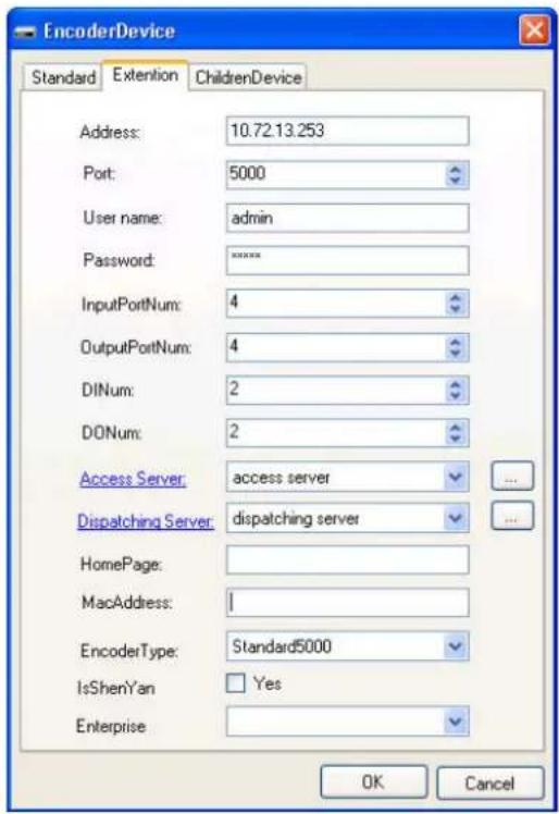
Address: IP address of the encoder.
- Access Server: Select the access server to which the encoder will connect from the drop-down list box.
- Dispatch Server: Select the dispatch server to which the encoder will connect from the drop-down list box.
Encoder Type: 8000+device
- Right-click the device information area, and select New Camera Device, as shown in Figure 128.
FIGURE 128 CREATE CAMERA

- Set the name and model of the camera, as shown in Figure 129.
FIGURE 129 ENCODER ADDED

- Set the extension information of the camera, as shown in Figure 130.
- Encoder Device: add the camera under a specified encoder. This item will be selected automatically. Make sure the encoder is the one you set in step 2 above.
Is Control: Select it.
FIGURE 130 CAMERA -EXTENDED INFORMATION SETTINGS

- Set the video information of the camera, as shown in Figure 131. Select Is Server Transmit, Dispatching Server, and Storage Server.
FIGURE 131 VIDEO INFORMATION OF THE CAMERA
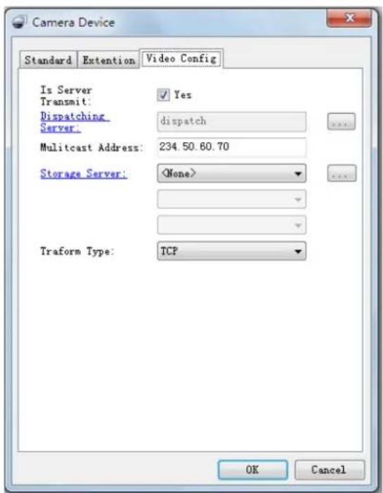
- Now the encoder and the camera are added. They are displayed in the list, as shown in Figure 132.
FIGURE 132 DEVICES ADDED
![ResourceExplorer Back Properties AfterMode * Search Clear Password Telnet Name ID Type Remark Create Offkai 000000 C30101111000001 Encoder Device 9000+ Camera Device1 C30101121000001 Camera Device [1] Camera Device2 C30101121000002 Camera Device [2]](/content/2026/05/1082591/images/2e5c683fb06dd532a68c45cfaa8b38443bd1f4fcc534533ef50a84d866d0b96e.jpg)
Write ZXVNMS Information into the Camera
- Log in to the IE configuration interface of the ZNNC MP-R188W-95-NC1T-B High Speed Dome. Choose Config Network Parameter Access Server IP to go to the Access Server IP window, as shown in Figure 133. The IP address and port of the registered host are those of the access server. Click Save to save the settings. Information of Heartbeat Host and Alarm Host is generated automatically.
FIGURE 133 ACCESS SERVER IP
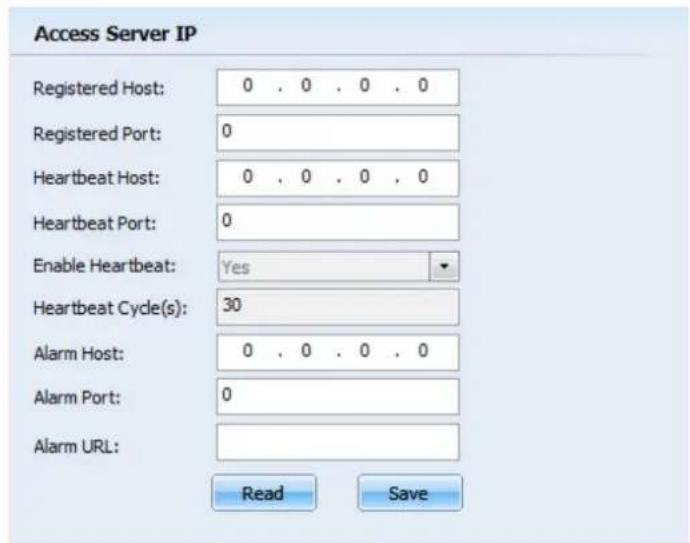
- Choose Config Basic Parameter Basic Information to go to the Basic Information window, as shown in Figure 134. Type the device name and ID. The device ID must be the same as that in the section "Creating Encoder and Camera on Management Client" above. Click Save to save the settings.
FIGURE 134 BASIC INFORMATION

Wire Gauge Conversion Table
TABLE 16 WIRE GAUGE CONVERSION TABLE
| Metric Bare Wire Diameter (mm) | Approx. AWG AWG | Approx. SWG SWG | Bare Wire Cross-Sectional Area ( mm2 ) |
| 0.050 43 47 0.00196 | |||
| 0.060 42 46 0.00283 | |||
| 0.070 41 45 0.00385 | |||
| 0.080 40 44 0.00503 | |||
| 0.090 39 43 0.00636 | |||
| 0.100 38 42 0.00785 | |||
| 0.110 37 41 0.00950 | |||
| 0.130 36 39 0.01327 | |||
| 0.140 35 0.01539 | |||
| 0.160 34 37 0.02011 | |||
| 0.180 33 0.02545 | |||
| 0.200 32 35 0.03142 | |||
| 0.230 31 0.04115 | |||
| 0.250 30 33 0.04909 | |||
| 0.290 29 31 0.06605 | |||
| 0.330 28 30 0.08553 | |||
| 0.350 27 29 0.09621 | |||
| 0.400 26 28 0.12570 | |||
| 0.450 25 0.16020 | |||
| 0.560 24 24 0.24630 | |||
| 0.600 23 23 0.28270 | |||
| 0.710 22 22 0.39580 | |||
| 0.750 21 0.44170 | |||
| 0.800 20 21 0.50270 | |||
| 0.900 19 20 0.63620 | |||
| 1.000 18 19 0.78540 | |||
| 1.250 16 18 1.22660 | |||
| 1.500 15 1.76630 | |||
| 2.000 12 14 3.14200 | |||
| 2.500 4.90800 | |||
| 3.000 7.06830 |
Factory Default Settings Table
The factory default settings of the dome are listed in Table 17.
TABLE 17 THE FACTORY DEFAULT SETTINGS
| Function Item | Factory Default Settings | Function Item | Factory Default Settings |
| IP Address 192. | 168.1.2 Resolution | 1280*720 or 1920*1080 | |
| Frame Rate | 25 | Encoding Mode | CBR |
| I frame Interval | 100 | Transmission Strategy | Constant rate |
| Max Bit Rate | 4096Kbps | Image Quality | Best |
| BLC Mode | Off | Day/Nite Mode | Auto |
| Password | 000000 | Mask Zone | Off |
| WDR Mode | Off | Interval of Nodes | 3s |
| North Reference | Location of horizontal position sensor | Scan Speed 100 | |
| Proportional Pan | On | Mission List | None |
| Protected | Off | Start At hh-mm | 00:00 |
| Zoom Speed | High | Mission Cycle | Off |
| Information | Off Action When Power | None | |
| DigiZoom Enable | On | Action When Idle | None |
| FocusNearLimit | 30cm | Enable | Off |
| WB Mode | Auto | Sensor | N/O |
| Slow AE | 1 | Action List | None |
| AE Mode | Auto | Alarm Output | N/C |
| FNR | Off | ||
Appendix F
Technical Parameters Table
Table 18 lists the technical parameters and functional characteristics of the ZNNC MP-R series High Speed Dome, in which W indicates outdoor installation, and N indicates indoor installation).
TABLE 18 DOME TECHNICAL PARAMETERS TABLE
| Model | ZNNC MP-R188W-95-NC1T-B | ZNNC MP-R202W-95-NC1T-A | ZNNC MP-R202W-95-NC3T-A | ZNNC MP-R202W-95-NC1T-B | ZNNC MP-R202W-95-NC3T-B |
| Lens | |||||
| Optical zoom 18 | 20 20 | ||||
| Focus length | f=4.7~84.6mm | f=4.7~94mm | f=4.7~94mm | ||
| F-number | F1.6~F2.8(Wide-Narrow) | F1.6~F3.5(Wide-Narrow) | F1.6~F3.5(Wide-Narrow) | ||
| Horizontal view angle | 55.2°~3.2° (Wide-Narrow) | 55.4°~2.9° (Wide-Narrow) | 55.2°~2.9° (Wide-Narrow) | ||
| Camera | |||||
| Sensor 1/3" CCD | 1/2.8" CMOS 1/2.8" CMOS | ||||
| Scan mode Interlaced scanning | |||||
| Total pixels | 1.32M | 3.27M | 3.4M | ||
| Resolution | 1280*720(16:9),1280*960(4:3) | 1920*1080 1920*1080 | |||
| SNR | 50dB | ||||
| Digi Zoom Enable | 12 | ||||
| Focusing | Auto/lock/manual | Auto/ manual | Auto/ manual | ||
| WDR Mode | Yes | ||||
| BLC Mode | Yes | ||||
| Day/NiteMode | Yes | ||||
| Minimum illumination | 0.02lux@F1.6(B&W);0.5 lux@F1.6(Color) | 0.005lux@F1.6(B&W);0.0 8lux@F1.6(Color) | 0.04lux@F1.6(B&W);0.4lux@F1.6(Color) | ||
| Shutter speed | 1/4~1/10000s | 1/1~1/10000s | 1/4~1/10000s | ||
| WB Mode | Auto/mercury lamp auto/sodium lamp auto/manual | Auto/indoor/outdoor/outdoor auto/auto track/sodium lamp auto/sodium lamp fix/manual | Auto/mercury lamp auto/sodium lamp auto/manual | ||
| DSS Auto | |||||
| Iris Auto/manual | |||||
| Slow AE | None | 1~48 speeds for setup | 1~255 speeds for setup | ||
| Mask Zone | 8 Masks can be set. A maximum of 4 Masks can be shown in a screen. | 24 Masks can be set A maximum of 8 Masks can be shown in a screen. | 8 Masks can be set. A maximum of 4 Masks can be shown in a screen. | ||
| DNR None Yes | None | ||||
| Partial Magnification | Yes | ||||
| Centered by clicking | Yes | ||||
| Functions | |||||
| Horizontal rotation | 360° continuous rotation, non-blind spot monitor, manual speed: 0.1~160 °/s, max. preset speed: 260 °/s. | ||||
| Vertical rotation | Angle: 30~-90°, manual speed: 0.1~120°/s, max. preset speed: 200 °/s. | ||||
| Auto flip 180°. Vertical -90°, auto flip 180° | |||||
| Proportional Pan | On/off | ||||
| North Reference | NorthReference point can be set. | ||||
| Preset 256 Presets | |||||
| Tour | 8. Each tour can be added with 24 Presets. | ||||
| AutoScan | 4. Each can be set with different Auto Scan intervals. | ||||
| Pattern | 4. Each can be recorded with 1000 directives. | ||||
| Schedules | 32 (Tour/Auto Scan/Pattern/Preset for each) | ||||
| Zonetips | 8. Display the zone tips in the configured areas. | ||||
| Action When Idle | Tour/AutoScan/Pattern/Preset. | ||||
| Action When Power | Recover/Tour/Auto Scan/Pattern/Preset. | ||||
| Action List | Tour/AutoScan/Pattern/Preset. | ||||
| Temperature measurement | Measure the real-time temperature on both sides of the internal dome. | ||||
| Date/Time | Set the date and time. | ||||
| Information | Coordinate/DomeTitle/Preset/ZoneTips/Pattern/Auto Scan/ Zoom/Date&Time/Temp. | ||||
| Execution priorityNetwork | Decrease by degree: ActionList -User Operation- Schedules - Action When Power - Action When Idle | ||||
| Network interface | 10Base-T / 100Base-TX, RJ45 connector | ||||
| Video encoding | H.264 encoding mode, encoding specification up to High Profile | ||||
| Audio encoding | Support audio encoding based on G.711 downlink and uplink audio | ||||
| Audio mode | 1 for two-way voice talk back Input, support voice Input of local talk back, connect to passive microphone or active audio collection device (such as pickup device);1 for two-way voice talk back output, support voice output of local talk back, this output can only be driven by active speaker. | ||||
| Protocol TCP/IP, | HTTP, DHCP, DNS, RTP/RTCP, PPPoE | ||||
| Max number of users | A maximum of 4 users | ||||
| SD card | Manual recording/Alarm recording, support Micro-SD card, support maximum of 32 GB . | ||||
| Client end | |||||
| Camera control | Horizontal/vertical, zoom, focus, partial magnification, centered by clicking, iris, call preset, and auto. | ||||
| Input/output interface | |||||
| Video output | Female BNC, 1.0±0.2VP-P(75Ω, Composite), anti-thunder grade : 4000V. | ||||
| Ethernet interface | RJ45 connector, anti-thunder grade: 2000V. | ||||
| Audio Interface | Two 3.5mm JACK, anti-thunder grade: 2000V. | ||||
| Alarm input 2-channel alarm input, anti-thunder grade: 2000V. | |||||
| Alarm output 2-channel alarm output, anti-thunder grade: 2000V. | |||||
| General specifications | |||||
| Power supply | AC24V±15%(ZNNC MP-R188W-95-NC1T-B, ZNNC MP-R202W-95-NC1T-A, ZNNC MP-R202W-95-NC1T-B);DC12V±10%~DC 48V±10%(ZNNC MP-R188W-95-NC1T-B, ZNNC MP-R202W-95-NC3T-A,ZNNC MP-R202W-95-NC3T-B); | ||||
| Power consumption | ≤50W | ||||
| Protection grade | IP66 | ||||
| Installation mode | Wall-mounting, suspension-mounting, wall corner-mounting, pole-mounting, and counterfort-mounting, in which wall corner-mounting, pole-mounting, and counterfort-mounting require users to purchase mounting bracket and accessories . | ||||
| Temperature/Humidity | Temperature: -30°C-+60°C (-22°F-+140°F); Humidity:10%~90%RH | ||||
| Size 191.9 × 155.5 × 434.4 (mm) | |||||
| Weight | About 5kg | ||||
- ZNNC MP-R188W-95-NC1T-B
- USER MANUAL
- LEGAL INFORMATION
- CONTENTS
- ABOUT THIS MANUAL .... I
- CHAPTER 1 .... 1
- PRODUCT OVERVIEW .... 1
- CHAPTER 2....7
- INSTALLATION....7
- CHAPTER 3....31
- OPERATING INSTRUCTIONS 31
- CHAPTER 4 ....35
- CONFIGURATION AND OPERATION 35
- CHAPTER 5....59
- MENU OPERATION....59
- APPENDIX A....97
- TERMS AND ABBREVIATIONS....97
- APPENDIX B....101
- FAQ....101
- APPENDIX C....105
- CONNECT TO THE ZXVNMS PLATFORM....105
- APPENDIX D....113
- WIRE GAUGE CONVERSION TABLE 113
- APPENDIX E 115
- FACTORY DEFAULT SETTINGS TABLE 115
- APPENDIX F 117
- TECHNICAL PARAMETERS TABLE 117
- ABOUT THIS MANUAL
- PURPOSE
- CONVENTIONS
- TYPOGRAPHICAL CONVENTIONS
- MOUSE OPERATION CONVENTIONS
- SAFETY SIGNS
- PREVENTIVE MEASURES
- SAFETY WARNINGS
- SAFETY CAUTIONS
- CHAPTER 1
- PRODUCT OVERVIEW
- NAMING CONVENTIONS
- APPEARANCE
- MAIN FEATURES
- CHAPTER 2
- INSTALLATION
- INSTALLATION PRECAUTIONS
- DIMENSIONS
- INSTALLATION MODES
- WALL-MOUNTING
- MOUNTING PARTS
- WALL-MOUNT BRACKET
- WALL-MOUNT BRACKET ACCESSORIES
- INSTALLATION STEPS
- DRILL HOLES AND MOUNT EXPANSION BOLTS
- MOUNT THE WALL-MOUNT BRACKET
- NOTE
- SUSPENSION MOUNTING
- MOUNTING PARTS FOR INDOOR SUSPENSION
- INSTALLATION STEPS FOR INDOOR SUSPENSION MOUNTING
- MOUNT THE BRACKET BASE
- MOUNT THE POLE, JOINT AND BRACKET ADAPTER
- MOUNTING PARTS FOR OUTDOOR SUSPENSION
- INSTALLATION STEPS FOR OUTDOOR SUSPENSION MOUNTING
- WALL CORNER MOUNTING
- 2 CORNER-MOUNT BRACKET
- MOUNT ACCESSORIES
- MOUNT THE CORNER-MOUNT BRACKET
- POLE-MOUNTING MODE
- ASSEMBLE THE POLE-MOUNT BRACKET
- MOUNT THE POLE-MOUNT BRACKET
- MOUNT THE WALL-MOUNTING BRACKET
- MOUNT THE DOME
- COUNTERFORT MOUNTING
- FIGURE 33 COUNTERFORT-MOUNTING
- DOME INSTALLATION
- MOUNT THE DOME BRACKET
- FIGURE 34 DOME BRACKET INSTALLATION
- MOUNT THE DOME CAMERA
- FIGURE 35 DOME UPPER COVER INSTALLATION
- FIGURE 36 MOUNT THE UPPER COVER ON THE WALL BRACKET
- MEMORY CARD INSTALLATION
- WIRE CONNECTIONS FOR THE DOME
- CONNECT ALARM INPUT/OUTPUT DEVICES
- DESCRIPTION OF CONNECTION CABLE
- CABLING
- CABLING REQUIREMENTS
- VIDEO CABLE
- NETWORK CABLE
- MATERIALS AND TOOLS
- PIN DEFINITION
- OPERATING INSTRUCTIONS
- POWER-ON SELF-TEST
- OPERATIONS FOR BASIC FUNCTIONS
- OPERATIONS FOR SPECIAL FUNCTIONS
- CHARACTER PROMPTS ON THE SCREEN
- CONFIGURATION AND OPERATION
- CONFIGURATION FLOW
- LOGIN
- CONFIGURING NETWORK PARAMETERS
- IP ADDRESS SETTING
- SETTING ON THE WEB
- SETTING WITH TELNET
- PPPOE DIALUP SETTING
- CLICK SAVE TO SAVE THE SETTING
- LOGGING IN TO OR RESTARTING THE CAMERA
- SETTING THE ACCESS SERVER IP ADDRESS
- SETTING THE DEVICE ID
- CONFIGURING I/O PARAMETERS
- SETTING CHANNEL PARAMETERS
- VIEWING A VIDEO
- VIDEO QUERY
- SETTING PRESET POSITIONS
- SETTING ENCODING PARAMETERS
- SETTING OSD PARAMETERS
- SETTING TITLES
- SETTING A STORAGE SCHEDULE
- SETTING ALARM PARAMETERS
- BASIC ALARM PARAMETERS
- SETTING DI LINKAGE PARAMETERS
- SYSTEM CONFIGURATION
- CHECKING DEVICE STATE
- STORAGE MEDIUM MANAGEMENT
- TIME SYNCHRONIZATION
- USER MANAGEMENT
- ADDING A USER
- SETTING USER PERMISSIONS
- MODIFYING A USER PASSWORD
- LOG QUERY
- DEVICE UPGRADE
- CHAPTER 5
- MENU OPERATION
- MENU OVERVIEW
- MENU TREE
- MENU OPERATIONS
- ATTRIBUTES OF THE MENU ITEM
- PASSWORD SCREEN
- PASSWORD
- MAIN MENU
- CONFIGURATION
- INFORMATION
- DISPLAY
- GLOBAL SET
- PATTERN
- AUTO SCAN
- COORDINATE
- TEMP
- EXIT
- NORTH REFERENCE
- PROPORTIONAL PAN
- OLD PASSWORD
- NEW PASSWORD
- NEW PASSWORD AGAIN
- PASSWORD CHARACTER SELECTION AREA
- BACK SPACE
- SAVE
- PROTECTED
- CAMERA BASIC PARAMETERS
- BASIC PARAMETERS OF THE "-B" MODEL
- ZOOM SPEED
- FOCUS NEAR LIMIT
- AF (AUTO FOCUS) MODE
- WB (WHITE BALANCE) MODE
- R-GAIN/B-GAIN
- APERTURE SET
- COLOR SET
- BASIC PARAMETERS OF “-A” MODEL
- DIGI ZOOM ENABLE
- HIGH SENSITIVITY
- WB MODE
- APERTURE
- CAMERA ADVANCED
- EXPOSURE MODE OF “-B” MODEL
- DAY/NITE MODE
- DAY / NITE MODE
- SWITCH AT DAY/SWITCH AT NITE
- ICR SENSITIVITY
- IR LED MODE
- ZOOM LENS LED
- FIX LENS LED
- IR PERCENT
- NOISE REDUCTION
- EXPOSURE MODE OF “-A” MODEL
- AE MODE
- SHUTTER
- IRIS
- BRIGHT
- GAIN
- DSSHUTTER
- WDR MODE
- DNR MODE
- BLC MODE
- SLOW AE
- DAY/NITE
- EXIT(MOVE THIS UP TO AFTER 11.)
- MASK ZONE
- MASK NUMBER
- ENABLE
- EDIT MASK
- DELETE CURRENT
- DELETE ALL MASKS
- MASK ZONE SETUP OF “-B” MODEL
- MASKZONE SETUP OF "-A" MODEL
- INTEGRATED PTZ
- PRESET
- EDIT SCENE
- TOUR
- ZONE TIPS
- PATTERN NUMBER
- PROGRAM
- RUN AND EXIT MENU
- SCHEDULES
- ACTION WHEN POWER
- ACTION WHEN IDLE
- ACTION LIST
- ACT AFTER
- OTHER FUNCTIONS
- WIPER
- DEFAULT
- CAMERA DEFAULT
- FACTORY DEFAULT
- RESTART
- APPENDIX A
- TERMS AND ABBREVIATIONS
- TERMINOLOGY
- BACKLIGHT COMPENSATION
- WIDE DYNAMIC
- ABBREVIATIONS
- APPENDIX B
- FAQ
- QUESTIONS ON IMAGES
- QUESTIONS ABOUT THE CONTROLLER
- QUESTIONS ABOUT THE INSTALLATION
- QUESTION 3: THE MEMORY CARD CANNOT BE DETECTED
- QUESTION 4: WHAT IS THE LENGTH OF THE VIDEO CABLE AND WHAT IS THE REQUIREMENT FOR THE CABLE
- CONNECT TO THE ZXVNMS PLATFORM
- CREATING THE ENCODER AND CAMERA ON THE MANAGEMENT CLIENT
- WRITE ZXVNMS INFORMATION INTO THE CAMERA
- WIRE GAUGE CONVERSION TABLE
- FACTORY DEFAULT SETTINGS TABLE
- APPENDIX F
- TECHNICAL PARAMETERS TABLE
Brand : ZTE
Model : MP-R188W
Category : Security Camera