
UHBX-8X - AV extender Hall Research - Free user manual and instructions
Find the device manual for free UHBX-8X Hall Research in PDF.


| Product Type | 8-Port HDMI Extender on HDBaseT |
| Brand | Hall Research |
| Model | UHBX-8X |
| Category | AV Extender |
| Number of HDMI Inputs | 8 |
| Number of HDBaseT Outputs | 8 |
| Maximum Extension Distance | Up to 500 ft (150 m) with compatible receivers and Long Reach mode |
| Supported Resolutions | Up to 4K UHD (4096x2160) – not in Long Reach mode |
| Video Standards | HDMI 1.4, DVI single link, HDCP, 3D, Deep Color |
| Audio Formats | LPCM 7.1, Dolby TrueHD, DTS-HD Master Audio |
| Control Interfaces | RS-232 (DB9), IP (RJ45 Telnet), USB (firmware update) |
| IR Extension | Bidirectional; supports modulation frequencies 30-60 kHz |
| Power-over-HDBaseT (PoH) | Yes (IEEE 802.3af, up to 6.49W per port, requires optional 48V supply) |
| Power Supply | Internal, universal input 100-240 VAC, 50/60 Hz |
| Power Consumption | 30 W max (102 BTU/hr) |
| Mounting | 1RU, fits standard 19-inch rack |
| Dimensions (H x W x D) | 1.75" x 7.75" x 19" (44.45 x 196.85 x 482.6 mm) |
| Weight | 6.9 lb (3.13 kg) |
| Cooling | Convection with internal temperature-controlled fan |
| Operating Temperature | 32 to 122 °F (0 to 50 °C) |
| Certifications | CE, FCC Class A |
| MTBF | 90,000 hours (calculated estimate) |
| Warranty | 2 years parts and labor |
| Included Accessories | Power cord, RS-232 cable |
| Optional Accessories | 48V PoH power supply (511-PS4815), IR detector cable (CIR-DET-P2), IR emitter cables (CIR-EMT, CIR-EMT2), locking HDMI cables |
Frequently Asked Questions - UHBX-8X Hall Research
User questions about UHBX-8X Hall Research
0 question about this device. Answer the ones you know or ask your own.
Ask a new question about this device
Download the instructions for your AV extender in PDF format for free! Find your manual UHBX-8X - Hall Research and take your electronic device back in hand. On this page are published all the documents necessary for the use of your device. UHBX-8X by Hall Research.
USER MANUAL UHBX-8X Hall Research

8-Port HDMI Extender on HDBaseT™ with IR, RS-232, and IP Control
Send 8 HDMI inputs to 8 remote displays up to 500 ft away Send PoH to power compatible receivers Extend IR in both directions
Send RS-232 and IR commands to any remote Display Control unit via RS-232 and IP ports
UMA1213 Rev B
Table of Contents
1.0 Introduction 3
2.0 Features 3
3.0 Setup 4
3.1 Package Contents 4
3.2 Extender Connections 4
4.0 Operation 11
4.1 Front Panel HDBaseT Status Indicators 11
5.0 Control Commands (RS232 and IP) 12
6.0 Troubleshooting 16
7.0 Specifications 18
TRADEMARKS USED IN THIS MANUAL
Hall Research and its logo are trademarks of Hall Research. Any other trademarks mentioned in this manual are acknowledged as the property of the trademark owners.
FCC RADIO FREQUENCY INTERFERENCE STATEMENT
This equipment generates, uses, and can radiate radio frequency energy and if not installed and used properly, that is, in strict accordance with the manufacturer's instructions, may cause interference to radio communication. It has been designed to comply with the limits for a Class A computing device in accordance with the specifications in Subpart B of Part 15 of FCC rules, which are intended to provide reasonable protection against such interference when the equipment is operated in a commercial environment. Operation of this equipment in a residential area is likely to cause interference, in which case the user at their own expense will be required to take whatever measures may be necessary to correct the interference.
Changes or modifications not expressly approved by the party responsible for compliance could void the user's authority to operate the equipment.




1.0 Introduction
The UHBX-8X is an 8-Port HDMI extender that converts 8 inputs to corresponding HDBaseT ™ outputs for extension to 150 meters/500 ft on single UTP. The extender supports HDCP, Deep Color, CEC, and 4K (UHD) resolutions. Compatible receivers include the economical UH-1BT-R or UH-1BTX-R for HDMI extension to 230 ft or 330 ft respectively, or the UHBX-R-PD which supports RS-232, IR, PoH and Long Reach modes to 500 ft.
When using receivers with PoH function, a single optional 48v power supply is needed for the 8-channel sender (Model # 511-PS4815).
The UHBX-8X provides both IP (Ethernet), and RS-232 ports for control. The user can address and send RS-232 or IR commands to any of the receivers to control the remote display. IR signals can also be extended in both directions. The UHBX-8X can generate IR commands to send to remote TVs but it also provides an IR detector input. The IR received by the detector can be routed to any particular or combination of outputs. 8 separate IR emitter ports are provided on the rear of the UHBX-8X The source of these signals would be IR detectors at each remote location. This would be perfect for controlling multiple sources in a rack remotely from where the TV's are located
The extender is constructed as a 1RU rack-mountable unit and has built-in power supply. LED indicators on the front panel show Link status, Video status, Long Reach, and PoH Power for each of the 8 outputs. The UHBX-8X is designed and manufactured in the USA.
2.0 Features
- Converts 8 separate HDMI inputs to corresponding HDBaseT™ outputs
- Extends IR in both directions
- Can issue RS-232 or IR commands to any output (requires compatible receiver)
• RS-232 and IP control ports
• Supports HDCP, 3D, Deep Color, CEC, and 4 K (UHD) resolutions - Sturdy 1RU design with built in power supply
- HDBaseT™ Compliant
- Can power compatible receivers through the cable using PoH (requires optional 48v supply)
- Front panel status indicators for power, link, video and more for each channel
- Designed and manufactured in the USA
8-Port HDMI Extender with Power, IR, and RS-232
3.0 Setup
3.1 Package Contents
The UHBX-8X is shipped with a power cord and an RS232 cable.
3.2 Extender Connections

Figure 1 - Extender Connections
As you may have noticed in the above picture the HDMI inputs are on the right side and the outputs are on the left. The reason for this arrangement is to allow easy construction of a 8x8 HDMI matrix that has HDBaseT outputs. Hall Research manufactures 8x8 HDMI matrices with the outputs on the right side. So if you stack the UHBX-8X with the above matrix, using short 5 inch patch cables you can add cross-point capability to the extender as shown below:

Figure 2 - Connecting 8x8 Matrix Switcher to the UHBX-8X
3.2.1 Extender Video Input Connections

Figure 3 - HDMI Inputs
Connect any one of the HDMI inputs to the source using quality HDMI cables. Hall Research offers compatible locking high-quality HDMI input cables with a convenient flip tab that can secure the input cables to the extender.
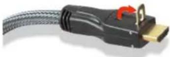
Figure 4 – Hall Research C-HDMI-L high bandwidth HDMI cable with flip-up locking tab
3.2.2 Extender Serial Data Connection
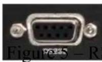
S232 Port
If required, plug a DB9 RS232 cable from any serial control device to the connector on the box. The RS232 port provides a bi-directional serial communication with any compatible receiver. This RS232 port operates at a fixed 19200 baud, 8-bit, no parity, and 1-stop bit. However, it can communicate with any compatible receiver at any user defined baud rate. Typically a straight-through male-to-female cable is used to connect to the extender. Pinout of the RS232 connector on the sender is shown below
| DB9-F Pin Term Direction | ||
| 2 | TX | Output |
| 3 | RX | Input |
| 5 | GND | |

Figure 6 – RS-232 path from UHBX-8X to remote receivers
3.2.3 Extender IP Connection

Figure 5 – IP Port
The RJ45 connector is a 10/100 Base-T Ethernet port. This IP port can be accessed via Telnet. As shipped, the IP address is configured for DHCP
8-Port HDMI Extender with Power, IR, and RS-232
(assigned by your network's router) and Port 6324 is used for Telnet communications. Telnet commands are the same as RS232 commands.
3.2.4 USB Connection

Figure 7 - USB Port
The USB port on the extender can be used to update the device firmware via a Windows GUI and to set the power saving mode if no RS-232 or IR are used. Please download the GUI software user guide for further information.
3.2.5 IR Connections
The extender can extend Infra-red Remote Control signals in both directions. It has one IR input connector for an optional IR detector cable, and 8 IR output connectors for optional IR emitter cables.
To provide maximum compatibility, IR signals are passed with their modulation frequency intact.
IR Signal from the UHBX-8X to compatible receivers

Figure 8 - IR Input
The UHBX-8X can generate IR signals by itself based on Telnet or RS232 commands. The generated IR signal can also be directed to any one or combination of outputs using simple ASCII control commands (see section 4 for further details).
Additionally, if an IR detector cable is plugged in to the IR input of the UHBX-8X, then this signal is also extended to the addressed receivers. In this way the user can use a TV's remote and point it at the IR detector that is plugged in to the UHBX-8X and be able to control the remotely located TV.
![graph TD A["IR Detector"] --> B["Σ"] C["LAN"] --> D["IP"] D --> E["IR Signal Generator"] F["Serial Controller"] --> G["RS-232"] G --> E B --> H["SW 1"] B --> I["SW 2"] B --> J["SW 3"] B --> K["SW 4"] H --> L["Output #1"] I --> M["Output #8"] J --> N["Output #8"] K --> O["Output #8"] L --> P["UHBX-R-…](/content/2026/05/1082231/images/eea0c27f385371010646eeec6178833d7839c86c72e02d787686ef1735faad15.jpg)
Figure 9 – IR path from UHBX-8X extender to remote locations
8-Port HDMI Extender with Power, IR, and RS-232
To generate IR commands using RS232 or IP commands, the user must know the protocol (NEC, Sony, RC5, etc), IR address, and IR command bytes. If these are not known the UHBX does provide the means to send “learned” IR codes, but to learn the codes a Hall Research model HR-4P may be needed. The IR send command for “learned” codes are typically a series of 64 Hex bytes that precisely define the IR signal to be generated.
IR Signal from a compatible receiver to the UHBX-8X
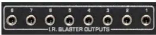
Figure 10 - IR Outputs
If there are IR detector cables plugged in at the remote receivers, those signals are extended to the UHBX-8X and are available at the IR Output connectors.
![graph LR A["STB #1"] -->|HDMI| B["UHBX-8X"] C["STB #8"] -->|HDMI| B B -->|UTP| D["UHBX-R-PD"] D -->|HDMI| E["Image Panel"] D -->|IR Detector| F["User Interface"] B -->|UTP| G["UHBX-R-PD"] G -->|HDMI| H["Image Panel"] G -->|IR Detector| I["User Interface"] B -->|IR Emitter| J["Input Signal"]](/content/2026/05/1082231/images/8c9d0f1f3ad5d202a4e3b11e9bf3446c241cfde85bda8ef9f1dff2f4cec3da4c.jpg)
Figure 11 – IR path from Display location to Source location
IR Detector Cable
The UHBX-8X uses “pass-thru” IR detector cable that maintains the IR modulation. Compatible cables are available from Hall Research (Model Number CIR-DET-P2). Pin out: Tip=Data, Ring=+5V DC, Sleeve=GND

Figure 12 – IR Detector Cable CIR-DET-P2 (Detector head has adhesive backing)
IR Emitter (Blaster) Cables
Currently two IR emitter cables are available: CIR-EMT and CIR-EMT2.
CIR-EMT, shown below, is recommended for most applications

Figure 13 –
IR Emitter Cable CIR-EMT
(Emitter has adhesive backing)
Pin out: Tip=Anode, Ring=Cathode, Sleeve=Not Connected
An alternative Emitter cable is CIR-EMT2. This cable is better suited for situations where there is a need to isolate and confine the IR signal to just one device. A separately sold adhesive rubber cover can be used to confine the IR beam to just one target device. The CIR-EMT2 is placed in a cavity in the cover and stuck on the target device directly over its IR sensor. A typical application scenario is when several identical video sources are located in close proximity to each other and they need to be independently controlled.
The CIR-EMT2 has a mono-type plug. Pin out: Tip=Anode, Sleeve=Cathode
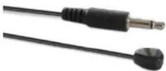
Figure 14 –
Alternate IR Emitter Cable CIR-EMT2
Figure 15 – Emitter Cover: CIR-EMT2-CVR (shown with CIR-EMT2)

3.2.6 UTP (Twisted Pair Catx) Connection

Figure 16 – HDBaseT outputs (RJ45 Connectors)
The extender is designed to be used with CAT6 UTP (unshielded) or STP (shielded) cabling. However, CAT5e cables may be used but the maximum cable length will be reduced by approximately 20% depending on the quality of the cable.
Augmented CAT6 cables can also be used, and are recommended for extension distances exceeding 140 meters (or >450 feet) with receivers that support Long Reach mode.
8-Port HDMI Extender with Power, IR, and RS-232
T568A termination standard is recommended for the UTP cable, However T568B will also work (as long as both ends are terminated the same way).
To avoid interference with video, in EMI noisy environments (such as close proximity to power transformers or AC wiring) shielded twisted pair (STP) cable would be recommended. If STP is used it is important to ensure that the RJ45 connector on both ends of the cable have the required metal shroud and that the cable shield/drain wire is electrically connected to the metal shroud and carried through from the sender to the receiver.
When Class-A HDBaseT receivers are used (such as Hall Research UH-1BTX-R or UHBX-R-PD), then the signal in the UTP can be strengthened by enabling Long Reach mode of operation. In this mode not only you can extend the signal beyond 100 meter limit, but also the signal is more immune to noise and interference even if the length of the cable is less than 100 meters. The UHBX-R-PD receiver has a small switch on the box that sets its mode to either Standard, or Long Reach, so the switch should be used to set the desired mode. The UH-1BTX-R, does not have a mode switch, however the mode can be set on the UHBX-8X using the Windows GUI. If you are using UH-1BTX and would like to set the link mode to Long Reach, you can do that using the Windows GUI through the USB connection. This is a onetime setting and the UHBX-8X will remember the mode set for each output. Please refer to the Windows GUI User's Guide (available on-line) for more information.
3.2.7 Powering Receivers Using PoH (Power-over-HDBaseT)
The extender has a built-in universal power supply with a standard IEC320 C14 plug. If compatible receivers with PoH function (Such as Hall Research UHBX-R-PD) are used with the extender, an external 48v power supply must be plugged in to provide power to all receivers connected to the UHBX-8X.

Figure 17 - Optional 48v Power Supplies Model 511-PS-4812 (4 pin used on early models) Model 511-PS4815 (3 pin used on latest models)
NOTE ABOUT POWER SUPPLIES
CHECK carefully to see which power supply you need for your system The latest models use a 3 pin power supply (Model 511-PS4815) Earlier models use a 4 pin power supply (Model 511-PS4812)
The Front panel of the UHBX-8X provides LED indicators for both the AC and the optional 48 vDC power inputs.

Figure 18 – Front panel power indicators
4.0 Operation
Once all the input and output connections are made as described in the previous section, connect AC power to the UHBX-8S. There is no separate on/off switch, so application of AC power will turn the unit on. Verify power supply operation on the front panel indicators. If a UHBX-R-PD is used as the receiver (needs PoH), make sure the optional 48V power supply is connected to the sender and the 48V DC light is lit on the front panel.
In compliance with HDBaseT Alliance recommendations, the UHBX-8X performs IEEE802.3af low-voltage handshake prior to inserting 48v onto the Cat6 cables. This process can take up to 3 seconds. Once PoH is successfully sent to each receiver the PoH LED on the front panel (and on the Receiver) will be lit. When the Link LED on Sender and Receiver are lit (or blinking) the system is ready to extend video and if you have source video connected, it should be visible on the remote displays.
If you are using UH-1BTX receivers and want to extend beyond the 100meter range, or if you are having video blanking issues (due to inferior UTP cable or electrical interference), you can set the HDBaseT mode of any of the 8 outputs to Long Reach using the Windows GUI software.
Also since HDBaseT has limitations regarding sending RS-232 and IR signals in low power mode, when connected to receivers that have IR or RS-232 (such as UHBX-R-PD), the UHBX-8X keeps the HDBaseT link fully active at all times even if there is no video. If you are using UHBX-R-PD as receiver, but are not using the RS-232 nor the IR functions, it is recommended that you turn on “power management” using the GUI. This will cause both the sender and the receiver to go into low power mode if no display is detected or if there is no video input. The HDBaseT chipsets consume only a fraction of power when they are in low power mode.
4.1 Front Panel HDBaseT Status Indicators

Figure 19 –HDBaseT status indicators on the front panel
| Link Solid on means the UHBX-8X Sender & remote Receiver are communicating Blinking means they are communicating in Low-Power (sleep) mode |
| Video Solid on means Video is being sent to the display |
| L.R. Solid on means the link is operating in Long Reach mode |
| PoH Solid on means PoH handshake successful and power is sent to receiver |
If all the LED's on the front panel are blinking together, then the unit has detected an over temperature condition and is performing a partial shutdown to prevent damage to the integrated circuits. This condition is reversible and when the temperature decreases to acceptable levels the extender begins to function normally again. If over temperature condition occurs frequently, then the user must allow better cooling and air flow around the box. The enclosure has a temperature controlled fan on the left side that draws in fresh air and exhausts the right side; make sure the sides of the unit are not blocking the flow of air.
If for a particular channel the Link, Video, and L.R. LEDs are blinking together, there has been a failure on the corresponding transmitter module or it is missing. Contact Support.
5.0 Control Commands (RS232 and IP)
The extender can be controlled using simple ASCII commands either through the RS232 or the Ethernet (IP) ports using Telnet protocol.
Use a DB9 Male-to-Female cable shipped with the extender to connect it to the computer or external control device. If using a PC open a serial terminal program (HyperTerminal, Realterm, TeraTerm, Putty, etc) with the following settings:
19200 Baud, 8 bits, No Parity, 1 Stop-bit, and No flow control.
All serial commands received will be followed by a response. Baud Rate and Parity setting commands (XBn and XPn) are global and affect all the outputs.
Command: XC, n
Connect serial interface (UART) to an output (n). If n is not specified, then it reports which output the controller is connected to.n is in the range of 1 to 8
Response: XC, n
This indicates that the command completed successfully
Command: XT Stands for Serial Transmit
This command should be followed by a string of characters (or bytes) to be sent. All byte received after this command end up in a FIFO and will be sent out after receiving a special two byte end of data designator (referred to as terminal characters). Therefore, the UHBX-8X does not distinguish between ASCII or Hex data, all data are treated as bytes. The user has 1-5 seconds to enter any data or characters, or a timeout will occur. The maximum number of bytes being sent out can not exceed 160 characters.
The terminal characters indicating the end of string are 0x17 followed by 0x0D. If everything is in ASCII and you are entering the string from a PC keyboard you can send 0x17 0x0D, by pressing Ctrl+w (will send 0x17) followed by Enter (will send 0x0D). If more than 160 bytes need to be sent, then multiple commands will be needed.
Response: OK
It is recommended that the customer wait for the OK response prior to issuing further commands. Neglecting to do so runs the risk of corrupting the internal buffers.
Example of XT Command
From a PC Keyboard
Type: XT [enter]
Type: Hello World [Ctrl+w] [enter]
This will send out "Hello World"
Command: XB,n
If n is not specified, it reports the current baud rate (n = 1-8 per table below)
| N 1 | 2 | 3 | 4 | 5 | 6 | 7 | ||
| Baud Rate | 1200 | 2400 | 4800 | 9600 | 19200 | 38400 | 57600 | 115200 |
Response: XBn
Command: XP,n
If n is not specified, it reports the current parity. n: (0 = None, 1=Odd, 2=Even)
Response: XP,n
8-Port HDMI Extender with Power, IR, and RS-232
Command: IC,n1,n2,n3, ...
Unlike Serial Connect command where the connection is made to one particular output at a time, the IR Connect command can simultaneously connect to multiple outputs. n1, n2, etc are output ports that the IR transmit signals (from extender to the remote receivers) will be routed to. If n=0 then all outputs are disconnected. The IR send connection pattern is stored in memory. As shipped from factory IR signals are connected to all 8 outputs.
Response: IC, n1, n2, n3, ...
Examples of IC command:
| Command Response | |
| IC,2,4,6<cr> IC,2,4,6<cr> Route IR to outputs 2,4, and 6 | |
| IC<cr> IC,2,4,6<cr> IC command with no parameters reports current IR connections | |
| IC,*<cr> IC,1<cr> | Connect to ALL ouputs (* = wildcard) |
| IC,2<cr> | |
| : | |
| : | |
| IC,8<cr> | |
| IC,0<cr> IC,0<cr> All outputs are disconnected | |
Command: ISk,m,n
| K 0 | 1 | 2 | 3 | 4 | 5 | ||
| Protocol | NEC | JVC | RCA | RC5 | Sony | Extended NEC |
m = IR address in decimal (range 0\~255, or 0\~65535 for Extended NEC) n = IR command in decimal
Response: ISk,m,n
Command: IS9
When all Hex bytes are entered, two special bytes (0x17 followed by 0x0D, called terminal characters) must be appended to the end of the data.
For further info and an example please refer to IR supplement available on line.
Response: OK
Command: CFn
| N 1 | 2 | 3 | 4 | |
| IR Freq | 36KHz | 38KHz | 40KHz | 56KHz |
Factory default is 38 KHz. This command should be used prior to issuing IS9 command if your IR signal is something other than 38 KHz. All infra red remote controls have a modulation (or carrier) frequency and the vast majority operate at 38KHz.
Response: CFn
Command: FD
This command will restore the unit to factory default condition, use with care.
Response: FD
This indicates that the command completed successfully
Command: FW
This command will report the firmware version in the unit. If the firmware is out of date, you can update the firmware using the USB port on the UHBX-8X.
Please see the Windows GUI Guide for further instructions.
Response: FWx.x
x.x is the version of the firmware in the device.
6.0 Troubleshooting
If you are experiencing problems getting the extender to work properly, please use the following troubleshooting suggestions.
a. Make sure that all of the connections on both the sender and the receiver are solid. Loose connections are the number one cause of issues.
b. Try resetting the system by unplugging the power supply connected to the sender, waiting 5 seconds and plugging it back.
c. Check the state of the LED's on the front of both the sender and the receiver. Refer to the table in section 4 to interpret the status being indicated.
d. If the cable length is longer than 100 meters (330 ft), then you must set the HDBaseT mode to "Long Reach". If you are using UHBX-R-PD then you should set the mode using the little slide switch on the receiver (below the HDMI output connector) to L.R. (Long Reach). If you are using UH-1BTX-R receiver which does not have a mode switch, then you have to set the mode on the UHBX-8X using the GUI via the USB connection. If you are using an HDBaseT Class B (lite) receiver such as the model UH-1BT-R, then you cannot set the mode to Long Reach since the Class B devices do not support this mode
e. In L.R. mode the unit does not support deep-color, nor 4Kx2K video. So you have to make sure your source does not output video with deep color or 4K (UHD) video.
f. Make sure the display is compatible with the video source by connecting them directly.
g. Make sure that the UTP or STP cable meets the requirements. Never use low-skew cable for digital video extension (low skew cables are suited for analog video extension, but do not work well for digital video). Read section 3.2.6 for UTP cable requirements.
h. The extender requires that the source DDC signals of its HDMI output operate at 100 KHz or less and support clock-stretching. The vast majority of sources meet these requirements. But if you determine that a particular source does not (by substituting a video pattern generator, or a different source), an HDMI transceiver may be needed. Hall Research offers the model EMX-HD-AUD that has a compatible output, can handle virtually any HDMI input, and has proven its ability to resolve source incompatibility issues.
i. If you are experiencing periodic video dropouts (where the screen goes blank for a few seconds every once in a while), try the following steps:
- Use a better twisted pair cable (23 Gage Shielded Cat6, or augmented Cat6
If your receiver supports Long Reach mode, set the mode to Long Reach (see steps d and e). We recommend doing this even if the cable length is less than 100 meters since in long reach mode the data rate in the UTP cable is much lower than in normal mode and hence the signal is less susceptible to ground noise, interference (be it electromagnetic, radio frequency, or static discharge), or quality of the UTP cable.
- Set the color depth of your source video to 8 bits (disable deep color), or lower the resolution.
○ Change the output mode of your source from YCbCr 4:4:4 to 4:2:2
If you are still not able to get the system working properly, contact Hall Research support (preferably via email or the form on support page of www.hallresearch.com) with a detailed description of the issue and the troubleshooting steps you have taken.
Do not open or try to repair the unit yourself as this will void your warranty. To return the extender for repair, you must contact HR Support at 714-641-6607 or via email or web. To ship the unit back for repair, make sure to obtain a Return Material Authorization (RMA) number.
7.0 Specifications
Video
Standards DVI (single link) and HDMI (compliant with HDMI 1.4 video specifications including 12 bit color depth, 3D video and 4K support)
Signal type TMDS
Connectors Locking HDMI
Resolutions DVI signal VGA (640x480) thru WUXGA (1920x1200)
HDTV signal 480i through 1080p
Digital Cinema 4K (4096x2160) – Not supported in Long Reach
Audio
Formats All HDMI Embedded Audio including: LPCM 7.1CH, Dolby TrueHD and DTS-HD Master Audio (32-192kHz sample rate)
Other Signals
DDC Pass-Thru DDC for reading EDID directly from remotely connected LCD and HDCP handshake. DDC clock must be less than 100 KHz and the source must support clock stretching
CEC Pass-Thru CEC for Consumer Electronics Control compatible devices
RS232 Bidirectional (full-duplex) any baud rate up to 115,200
IR Extended in both directions. Carrier modulation range from 30 KHz to 60 KHz
PoH Power-over-HDBaseT meets IEEE 802.3af standard. The UHBX-8X supports PoH power to devices that require power up to Class 2 (6.49 watts).
General
Power Supply 100 VAC to 240 VAC, 50-60 Hz, 1.5A, internal;
Power 30 watts (102 BTU/hr) maximum
Temp/humidity Storage: -40 to +158 °F (-40 to +70 °C) / 10% to 90%, non-condensing Operating: +32 to +122 °F (0 to +50 °C) / 10% to 90%, non-condensing
Cooling Convection, with internal temperature controlled fan
Mounting 1RU high, standard 19" rack
Enclosure type Steel
Dimensions 1.75" H x 7.75" W x 19" L (44.45mm H x 196.85mm W x 482.6mm L)
Product weight Extender 6.9 lb or 3.13 kg Shipping 8 lb or 3.6 kg includes: Extender, power cord, and manual
Vibration ISTA 1A in carton (International Safe Transit Association)
Safety CE
EMI/EMC CE, FCC Class A
MTBF 90,000 hours (Calculated Estimate)
Warranty 2 years parts and labor Specifications are subject to change without notice
HR HALL RESEARCH
© Copyright 2018. Hall Research, Inc. All rights reserved.
1163 Warner Ave., Tustin, CA 92780 Ph: (714)641-6607
- 8-PORT HDMI EXTENDER ON HDBASET™ WITH IR, RS-232, AND IP CONTROL
- TABLE OF CONTENTS
- TRADEMARKS USED IN THIS MANUAL
- FCC RADIO FREQUENCY INTERFERENCE STATEMENT
- 1.0 INTRODUCTION
- 2.0 FEATURES
- 8-PORT HDMI EXTENDER WITH POWER, IR, AND RS-232
- 3.0 SETUP
- 3.1 PACKAGE CONTENTS
- 3.2 EXTENDER CONNECTIONS
- 3.2.1 EXTENDER VIDEO INPUT CONNECTIONS
- 3.2.2 EXTENDER SERIAL DATA CONNECTION
- 3.2.3 EXTENDER IP CONNECTION
- 3.2.4 USB CONNECTION
- 3.2.5 IR CONNECTIONS
- IR DETECTOR CABLE
- IR EMITTER (BLASTER) CABLES
- 3.2.6 UTP (TWISTED PAIR CATX) CONNECTION
- 3.2.7 POWERING RECEIVERS USING POH (POWER-OVER-HDBASET)
- NOTE ABOUT POWER SUPPLIES
- 4.0 OPERATION
- 4.1 FRONT PANEL HDBASET STATUS INDICATORS
- 5.0 CONTROL COMMANDS (RS232 AND IP)
- COMMAND: XT STANDS FOR SERIAL TRANSMIT
- RESPONSE: OK
- EXAMPLE OF XT COMMAND
- 6.0 TROUBLESHOOTING
- 7.0 SPECIFICATIONS
- VIDEO
- AUDIO
- OTHER SIGNALS
- GENERAL
- HR HALL RESEARCH
Brand : Hall Research
Model : UHBX-8X
Category : AV extender