
CQ-4330U - Car Radio PANASONIC - Free user manual and instructions
Find the device manual for free CQ-4330U PANASONIC in PDF.


| Product Type | Car Radio |
| Brand | Panasonic |
| Model | CQ-4330U |
| DIN Size | 1-DIN |
| Dimensions (W x H x D) | 7 in x 2 in x 6 in (178 mm x 50 mm x 152 mm) |
| Weight | 1.5 lbs (0.68 kg) |
| Power Source | 12V DC (negative ground) |
| Maximum Power Output | 20W x 2 (RMS) |
| Frequency Range (AM) | 530 – 1600 kHz |
| Frequency Range (FM) | 87.5 – 108 MHz |
| Preset Stations | 18 FM / 6 AM |
| Cassette Mechanism | Auto-reverse, playback only |
| Equalizer | 5-band graphic equalizer |
| Clock | Digital display with time setting |
| Display Type | LCD with green backlight |
| Front Panel Security | Detachable faceplate |
| Additional Functions | Loudness control, fader/balance, local/distance tuning |
| Fuse Rating | 10A (ATC blade type) |
| Maintenance | Clean tape head monthly with isopropyl alcohol |
| Repairability | Spare parts available through Panasonic service centers |
Frequently Asked Questions - CQ-4330U PANASONIC
User questions about CQ-4330U PANASONIC
0 question about this device. Answer the ones you know or ask your own.
Ask a new question about this device
Download the instructions for your Car Radio in PDF format for free! Find your manual CQ-4330U - PANASONIC and take your electronic device back in hand. On this page are published all the documents necessary for the use of your device. CQ-4330U by PANASONIC.
USER MANUAL CQ-4330U PANASONIC
Heavy Duty Cassette/Weather Band Receiver with CD Changer Control / XM Radio Ready
CQ-4330U

Operating Instructions

natural_image
Black-and-white photo of a forest road winding through dense trees, no visible text or symbols
- Please read these instructions carefully before using this product and keep this manual for future reference.
Safety Information
WARNING:
TO REDUCE THE RISK OF FIRE OR ELECTRIC SHOCK OR PRODUCT DAMAGE, DO NOT EXPOSE THIS APPLIANCE TO RAIN, SPLASHING, DRIPPING OR MOISTURE.
CAUTION:
PLEASE FOLLOW THE LAWS AND REGULATIONS OF YOUR STATE, PROVINCE OR COUNTRY FOR INSTALLATION OF THE UNIT.
The following applies only in the U.S.A.
Part 15 of the FCC Rules
FCC Warning:
Any unauthorized changes or modifications to this equipment would void the user's authority to operate this device.
NOTICE:
This product contains lead in some components. Disposal of these materials may be regulated in your community due to environmental considerations.
For disposal or recycling information please contact your local authorities, or the Electronics Industries Alliance: http://www.eiae.org.
Find the model number and serial number on either the back or bottom of the unit. Please record them in the space below and retain this booklet as a permanent record of your purchase to help with identification in case of theft.
MODEL NUMBER CQ-4330U SERIAL NUMBER
DATE PURCHASED FROM
Panasonic welcomes you to our ever growing family of electronic product owners. We know that this product will bring you many hours of enjoyment. Our reputation is built on precise electronic and mechanical engineering, manufactured with carefully selected components and assembled by people who take pride in their work. Once you discover the quality, reliability, and value we have built into this product, you too will be proud to be a member of our family.
□ Use this product safely
When Driving
Keep the volume level low enough to be aware of road and traffic conditions.
When Car Washing
Do not expose the product, including the speakers and tapes, to water or excessive moisture. This could cause electrical shorts, fire, or other damage.
When Parked
Parking in direct sunlight can produce very high temperatures inside your vehicle. Give the interior a chance to cool down before switching the unit on.
Use the Proper Power Supply
This product is designed to operate with a 12 V DC, negative ground battery system.
Protect the Tape Mechanism
Keep magnets, screwdrivers, or other metallic objects away from the tape mechanism and tape head to prevent poor performance or malfunctions.
Note: The preset memory is cleared to return to the original factory setting when the power connector or battery is disconnected.
What is XM Satellite Radio?
XM Radio is broadcastiog over 120 digital channels of totally new music, news, sports and children's programming direct to vehicle and homes via satellite and our extensive repeater network, which supplements the satellite signal to ensure seamless transmission. The channels originate from XM's broadcast center, the world's largest all-digital studio complex in Washington, DC, and uplink to our two (Boeing 702) satellites. These satellites transmit the signal across the entire continental United States. Each satellite provides 18kw of total power making them the two most powerful commercial satellites ever built, providing coast-to-coast coverage. XM Satellite Radio is changing the way people listen to radio in the same way cable changed television.
Accessories
- Operating Instructions .... 1
- Supplied Hardware....1 set (→ page 23)
- Warranty Card....1
Contents
Safety Information (Part 15 of the FCC Rules) ...... page 2
Notice 2
Use this product safely 3
Accessories 3
Power and Sound Controls 5
Power, volume, mute, loudness, audio mode (Bass/Treble/Balance/Fader)
□ Clock Setting....7
Clock display change, Initial time, time setting and reset
□ Alarm Time Setting....8
Initial alarm time, alarm time setting and reset, alarm operation, alarm output volume selection
□ Radio....9
Radio mode, band, manual tuning, seek tuning, preset station setting, preset station calling, weather band station tuning
□ Cassette Tape Player 12
How to load, Rewind, Fast forward, play side change, eject a cassette tape



□ CD changer control .... 14
Play, repeat, random, scan, error messages
Note: CD changer controls are applicable to units with optional CD changer unit (sold separately)
□ XM Control....16
XM Mode, Band, Channel Selection, Category Priority Setting and Selecting, Manual Preset Memory. Preset Memory Calling, Display Change, XM ID Confirmation, Error Display

□ Troubleshooting 19
Preliminary steps, if you suspect something wrong, troubleshooting tips
☐ Speaker connections 21
□ Product servicing 21
□ Maintenance....21
□ Installation Guide....22
Overview, required tools, dashboard specifications, identify all leads, connect all leads, final installation, final checks, preparation, dashboard installation, installation hardware, to remove the unit
□ Electrical Connections 26
Caution, wiring diagram

□ Specifications....29
Power and Sound Controls
![Power Turn the key in the ignition until the accessory indicator lights. Power on: Press [PWR] (power). Power off: Press [PWR] (power) again. ACC ON Volume Turn the knob clockwise to increase volume, and counterclockwise to decrease volume. Vol 18 Volume level (0 to 40) (default: 18) Down Up HD SERIES MOBINED BAND PWR APM DISP BAND MODE VOL 20 Am 8:15 DISC CD SEM RPT ROM 1 MTL 2 NR 3 TPS 4 REP 5 SKP 6 Panasonic CO-4330U CLK ALM LOUD MUTE SC N TUNE SEEK Mute Press [MUTE] to mute the sound completely. Mute blinks Press [MUTE] again to cancel. Loudness Press and hold [MUTE] (LOUD) for more than 2 seconds. to enhance bass and treble tones at low or medium volume. Loudness indicator Press and hold [MUTE] (LOUD) for more than 2 seconds again to cancel.](/content/2026/05/1081827/images/de130d8de0f8ad96f3b32e3a8159f5e44bb42c71c79e4bbacc3073a27812f28b.jpg)
Power and Sound Controls (Continued)
Audio Modes
(Bass/Treble/Balance/Fader)
①
Push [SEL] to select the audio mode.

flowchart
graph TD
    A["VOLUME"] --> B["BASS TREBLE"]
    B --> C[" "]
    C --> D["BALANCEF"]
    D --> E["push"]
    E --> F[" "]
    F --> G[" "]
    G --> H[" "]
    H --> I[" "]
    I --> J[" "]
    J --> K[" "]
    K --> L[" "]
    L --> M[" "]
    M --> N[" "]
    N --> O[" "]
    O --> P[" "]
    P --> Q[" "]
    Q --> R[" "]
    R --> S[" "]
    S --> T[" "]
    T --> U[" "]
    U --> V[" "]
    V --> W[" "]
    W --> X[" "]
    X --> Y[" "]
    Y --> Z[" "]
2

Turn [VOL] (volume) clockwise or counterclockwise to change each level.
Bass:

Treble:

Balance:

Fader:

Note: If no operation takes place for more than 5 seconds in audio mode (2 seconds in volume mode), the display returns to the regular mode.
Illumination Switching
Press [SCAN] (ILL) for more than 2 seconds to switch the illumination color (green/amber).
Selecting the Clock Display
Press [CLK] (clock) to switch clock and alarm time display both.

Note: if no operation takes place for more than 5 seconds in alarm time, the display returns to the clock display.
The 12-hour system is used for the clock.
Initial Time

"SET" is displayed when the clock is not adjusted.
![Operation takes place for more than 5 nds in alarm time, the display returns to the k display. PWR APM BAND DISP MODE HD SERIES WEATHER BAND CLK ALM Panasonic CO-4330U VOL FUSH SEL/SAT BASS/TREB BAL/FADER FM1 879 AM 8:15 DISC CD SEM RPT ROM 1 MTL 2NR 3TPS 4REP 5 SKP 6 LOUD MUTE SCAN ILL TUNE SEEK [V] (Hours) [∧] (Minutes)](/content/2026/05/1081827/images/039eb5e04bdff3dff6c2d50dd6a19e9ae1a89a344c6668a83dd8de1d1c902343.jpg)
Time Setting
① Press and hold [CLK] (clock) and do not release to set time. Display blinks and the time setting mode is activated.

Hours
② Press [V] to set the hour.

Minutes
③ Press [∧] to set the minute.

④ Once the time has been set, release [CLK].
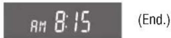
Note: Press and hold [V] or [∧] to change numbers rapidly.
Time Reset
When you want to reset the time, repeat steps ① to ④.
Note: the current time will be displayed at all the time even the power of the radio is turned off.
The 12-hour system is used for the clock.
Initial Alarm Time
Press and hold [ALM] (Alarm)
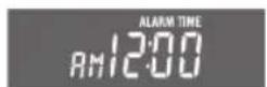
"AM 12:00" is displayed when the alarm is not adjusted.
![APM DISP PWR BAND MODE HD SERIES ALM CLK VOL FUSH SEL/SAT BASS/TREB BAL/FADER Panasonic CO-4330U FM 1 879 AM 8:15 DISC CD SCAN RPT ROM 1 MTL 2 NR 3 TPS 4 REP 5 SKP 6 LOUD MUTE TUNE SEEK SCAN ILL [V] (Hours) [A] (Minutes)](/content/2026/05/1081827/images/1e11a1232ea35368bac1b6e1ce4406a540d951b0629c281c50ad25516fda235b.jpg)
Alarm Time Setting
① Press and hold [ALM] (Alarm) and do not release to set alarm time. Display blinks and the alarm time setting mode is activated.

Hours
② Press [V] to set the hour.

Minutes
③ Press [∧] to set the minute.

④ Once the alarm time has been set, release [ALM].
Note: Press and hold [V] or [∧] to change numbers rapidly.
Alarm Time Reset
When you want to reset the alarm time, repeat steps ① to ④.
Alarm Operation
- Alarm is switched to ON or OFF each time [ALM] is pressed.
- When the alarm is switched to ON, the alarm will sound at the set alarm time.
Turning off the Alarm Sound
The alarm will turn off automatically after 90 seconds. Otherwise, press [ALM] once.
Alarm output Volume Selection
You can select ALARM VOL 1 (or VOL 2) by pressing [ALM] in sequence and the display will show as follows.
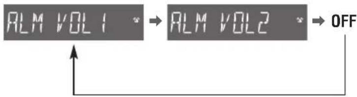
flowchart
graph TD
    A["RLM VOL1"] --> B["RLM VOL2"]
    B --> C["OFF"]
    C --> D["Feedback to A"]
Cautions:
- Be careful not to set wrong alarm time, otherwise, the alarm may sound while driving.
- If the alarm is set, be sure to check the set alarm time by pressing [CLK].
- If volume is set at "0" level, the output volume will be muted. (Even when ALARM is acting.)

flowchart
graph TD
    A["Radio"] --> B["TAPE CD Changer Control"]
    B --> C["(When a Tape is inserted)"]
    B --> D["(When a CD changer is connected)"]
    E["FM stereo indicator"] --> F["Panasonic CO-4330U"]
    F --> G["1 MTL 2 NR 3 TPS 4 REP 5 SKP 6"]
    H["Band"] --> I["Press [BAND"] to change the band.]
    I --> J["FM1 → FM2"]
    J --> K["AM ← WD"]
    L["Scan"] --> M["Press [SCAN"], each station will be scanned sequentially and the display will blink for 5 seconds.]
    L --> N["Press [SCAN"] again to stop scanning and the last station will continue to broadcast.]
[∧]: Higher frequency
[V]: Lower frequency
Seek Tuning
Press and hold for more than 0.5 seconds and release it.
[∧]: Higher frequency
[V]: Lower frequency
Tuning will automatically stop when the signals of the next broadcast station is received.
Preset Station Setting
Up to 6 stations can be saved in each of the FM1, FM2 and AM preset station memories.
Note: Existing saved stations are overwritten with new stations after following this procedure.
① Band
Press [BAND] to select a desired band.
(→ page 9)
![APM DISP PWG BAND MODE HD SERIES WECOTHER BAND CLK ALM Panasonic CQ-4330U VOL PUSH SEL/SAT BASS/TREB BAL/FADER FM1 879' AM 8:15 DISC CD SCN RET ROW 1 MTL 2 NR 3 TPS 4 REP 5 SKP 6 LOUD MUTE SCAN ILL TUNE SEEK Preset buttons from [1] to [6]](/content/2026/05/1081827/images/8fd589a5137f91006c108c937439ebc5613544b78647468ae9c3e1e88e5f9683.jpg)
② Auto Preset Memory (APM)
Press and hold [BAND] (APM: auto preset memory) for more than 2 seconds.
- The 6 stations with good reception will be automatically saved in the memory under preset buttons from [1] to [6].
- Once set, the preset stations are sequentially scanned for 5 seconds each.
- Press [BAND] again to stop sequentially scan.
Manual Preset Memory
① Use manual or seek tuning to find a station. (→ page 9)
② Press and hold one of the preset buttons from [1] to [6] until the display blinks once.
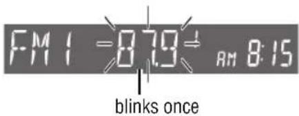
Preset Station Calling
Press the corresponding preset button from [1] to [6] to tune in a preset station.
Caution: To ensure safety, never attempt to preset stations while you are driving.

Tuning in a Weather Band Station
- Press [BAND] to select WB (Weather Band). (→ page 9)
- Press any of the buttons [1] to [6] to monitor the preset station.
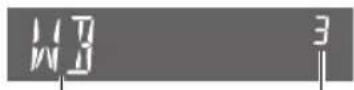
WB
Weather Band Frequency (channel) Number
Note: The weather band (CH1-6) has been preset. CH7 is selected by pressing [∧] or [∨].
Weather Band Stations
National Weather Radio Broadcasts from over 380 locations throughout the U.S. on seven VHF/FM frequencies.
Tune to weather band to receive continuous weather information 24 hours a day on one of the following frequencies.
- 162.550 MHz
2.162.400 MHz
3.162.475 MHz
4.162.425 MHz
5.165.450 MHz
6.162.500 MHz
7.162.525 MHz
Occasionally the frequency of an existing or planned station must be changed because of unexpected radio frequency interfere with adjacent NOAA weather Radio Stations and/or with other Government or commercial Operations within the area. If you have a question concerning NOAA Weather Radio, please contact your nearest National Weather Service Office.
Cassette Tape Player
Loading a Cassette
Insert the cassette with the exposed tape side facing to the right. Gently push the cassette in until the loading begins. The cassette will be loaded in place and playback starts.

Program Indicator

Caution: Do not insert a tape when "tape" indicator "△" or "▽" lights.
Note: To maintain your cassette player in top condition, avoid using tapes that are longer than 90 minutes (C-90).
Notes on Cassette Tapes
Tape Slack:
Use a pencil or similar object to take up the slack as shown. If a loose tape is used, this may result in the tape becoming tangled in the rotating parts of the unit.

Ejecting the Tape
Press [▲] and the cassette will eject for removal, and the previous mode of operation will be resumed.
Notes:
- If power is switched off before [▲] is pressed, the cassette will not eject. Switch on the power again and press [▲] to eject the cassette.
- The cassette tape should always be removed from the cassette slot when not in use.
Play Side Change
Press [◀▶] to switch to the program on the other side of the tape.
The display changes to indicate which program is playing.

Top Side Playing

Bottom Side Playing
Cassette Head Cleaning Warning
- The display will show "CLN HEAD" to remind you to clean the cassette head after accumulating 100 hours tape playing.

- Press and hold [◀▶] for more than 2 seconds to clear the "CLN HEAD" display and the TAPE mode display will resume. (It is valid only in TAPE mode.)
Rewind and Fast Forward
Press [◀◀ TRACK] or [▶▶ TRACK] to activate rewind or fast forward of the tape.

Press [◀▶] to stop rewind or fast forward.
If you rewind the tape fully, it will play on the same program side again.
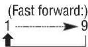
If you fast forward to the end, play will resume from the beginning of the other side of the tape.
Metal Tape Mode
Press [1] (MTL) when playing metal or chromium dioxide (CrO2) tapes.
Press [1] (MTL) again to cancel.
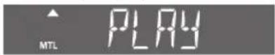
Note: Playing normal tapes in metal tape mode causes high frequency imbalance, which affects tone quality.
Dolby B Noise Reduction
Press [2] (NR) to set the Dolby B NR mode. Press [2] (NR) again to cancel.

Note: Set the Dolby B NR mode when playing back a tape recorded with Dolby B Noise Reduction.
Tape Program Search (TPS) Operation
① Press [3] (TPS) to activate the tape program search mode.

② To select a desired program, press [▶▶ TRACK] or [◀◀ TRACK] corresponding times to go forward (up to 9) or backward (up to 8).
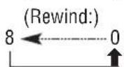
③ Press [3] (TPS) again to cancel.
Blank Skip
Press [5] (SKP) to skip unrecorded portions longer than 15 seconds on the tape.
Press [5] (SKP) again to cancel.

Note: When repeat is on, the blank skip does not work because the repeat has priority over the blank skip.
Repeat Play
Press [4] (REP) to repeat the current program.
Press [4] (REP) again to cancel.

Note: The TPS and SKP mode may not work correctly in the following cases. This, however, does not mean that the unit is defective.
- There is an interval less than 3 (15 in SKP mode) seconds or having a high level of noise or hum between programs.
• There is particularly low-level passage during the program.
CD Changer Control
① CD Changer mode
While a disc magazine is inserted in the CD changer, press [MODE] to select CD changer mode.
Play starts from the first track.

② Disc Selection
[1] (√ DISC): Previous disc.
[2] (∧ DISC): Next disc.
③ Track Selection
Press [TRACK ▶▶] once to go to the next track. Press repeatedly to step forward through all the tracks.
Press [TRACK ◀◀] once to play from the beginning of the current track, Press twice to play the previous track. Press repeatedly to step backward through all the tracks.
Track Search
Press and hold [TRACK ▶▶] or [TRACK ◀◀] for more than 0.5 seconds to activate fast forward or reverse through a track.
Release it to resume the normal CD play from that position.
Note:
CD changer functions are applicable to units with optional CD changer unit. (sold separately)
Scan Play (Tracks)
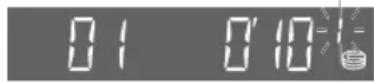
- Press [4] (CD SCAN). The track number blinks and the first 10 seconds of each track on the discs play in sequence.
- Press [4] (CD SCAN) again to cancel and continue with the current track.
blinks

Scan Play (Discs)
- Press and hold [4] (CD SCAN) for more than 2 seconds. The first track of all the discs in the magazine is played for 10 seconds each and Disc Number blinks.
- Press and hold [4] (CD SCAN) for more than 2 seconds again to cancel.
blinks
Repeat Play (Tracks)
- Press [5] (RPT) to repeat the current track.
- Press [5] (RPT) again to cancel.
lights REP: Repeat Indicator

Repeat Play (Discs)
- Press and hold [5] (RPT) for more than 2 seconds to repeat the current disc.
- Press and hold [5] (RPT) for more than 2 seconds again to cancel.
blinks REP: Repeat Indicator

Random Play (Tracks)
- Press [6] (RDM) to random selection. Music is played from all available CDs.
- Press [6] (RDM) again to cancel.
lights R▶: Random indicator

Random Play (Discs)
- Press and hold [6] (RDM) for more than 2 seconds all the available tracks on the current disc play in a random sequence.
- Press and hold [6] (RDM) for more than 2 seconds again to cancel
blinks R▶: Random indicator

Error Display Messages
E1
Disc is dirty, or is upside down.
→ Select the next available compact disc. Check the disc.
82
Disc has scratches.
→ Select the next available compact disc. Check the disc.
E
No operation by some cause.
→ Eject the magazine. If failure persists, press the reset switch on the CD changer. If normal operation is not restored yet, call the store where you purchased the unit or the nearest panasonic service center to ask for repairs.
NO JISC
No disc in the changer (magazine)
→ Insert discs into the changer (magazine).
Preparation:
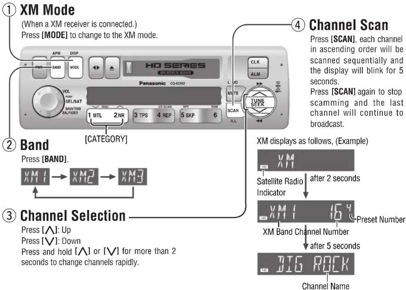
Connect the XM receiver (XM DIRECT MODEL:XM-RVR-D-001) to the Unit CQ-4330U. XM satellite radio is available on a chargeable basis.
flowchart
graph TD
    A["① XM Mode\n(When a XM receiver is connected.)\nPress [MODE"] to change to the XM mode.] --> B["② Band\nPress [BAND"].]
    B --> C["③ Channel Selection\nPress [∧"]: Up\nPress["∨"]: Down\nPress_and_hold["∧"] or["∨"] for more than 2 seconds to change channels rapidly.]
    C --> D["④ Channel Scan\nPress [SCAN"], each channel in ascending order will be scanned sequentially and the display will blink for 5 seconds.\nPress["SCAN"] again to stop scamming and the last channel will continue to broadcast.]
    D --> E["XM displays as follows, (Example)\nSatellite Radio Indicator after 2 seconds\nPreset Number\nXM Band Channel Number after 5 seconds\nBIG ROCK\nChannel Name"]
Category Priority Setting and Selecting
- Push the knob [SEL] for more than 2 seconds.

flowchart
graph TD
    A["Category"] -->|Push and hold| B["CAT ON"]
    A -->|without operation during 2 seconds.| C["CAT OFF"]
    B -->|when category is set ON.| D["ROCK"]
    C -->|when category is set OFF.| E["CAT ON"]
    D -->|category name| F["INTERDISPLAY FOR 2 SECONDS."]
    E -->|(blinks)| G["CAT OFF"]
    G -->|turn right| H["Turn Left"]
    G -->|Turn left| I["Turn Right"]
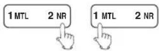
- When the display shows "CAT ON",
Press [2] (∧): Up
Press [1] (V): Down

flowchart
graph TD
    A["CAT ON"] --> B["(without operation during 5 seconds.)"]
    C["Category Name"] --> D["ROCK"]
    D --> E["Press [2"] or["1"].]
    E --> F["ROCK (Receiving)"]
    F --> G["(Received)"]
    H["Category Name"] --> I["URBAN"]
    I --> J["(interdisplay for 2 seconds.)"]
    J --> K["CATEGORY"]
    L["non 2 seconds"] --> M["XM1 164"]
    M --> N["category on indicator"]
Push and hold the knob [SEL] for more than 2 seconds to resume the normal display.
Notes:
CAT OFF: Every channel can be selected from every category.
CAT ON: Only channels in the current category can be selected.
Default: CAT OFF
Manual Preset Memory
Up to 6 channels each can be saved in the XM1, XM2 and XM3 preset station memories.
① Select a band and a channel.


② Press and hold [1] to [6] for more than 2 seconds to memorize.


• The channel number and the preset number blink once.
Note:
Existing saved channels are overwritten with new channels after the above procedure.
Preset memory Calling
① Select a band.

② Press [1] to [6].

flowchart
graph TD
    A["1 MTL 2 NR"] --> B["3 TPS 4 REP"]
    B --> C["5 SKP 6"]
Note:
When category is on category will be off after pressed any preset button [1] to [6].
Display Change
Press and hold [MODE] (DISP) for more than 2 seconds.

(Press and hold)

flowchart
graph TD
    A["BIG ROCK"] --> B["NAME"]
    B --> C["THE BEAT"]
    C --> D["TITLE"]
    D --> E["LOVE ME"]
    E --> F["CATEGORY"]
    F --> G["NEWS"]
Note:

Display when there is no name/title or can not decode.
XM ID Confirmation
- Push and hold the knob [SEL] for more than 2 seconds and then push again during 2 seconds.

flowchart
graph LR
    A["(Push and hold) (Push)"] --> B["←"]
    C["←"] --> D["→"]
    E["CATEGORY"] --> F["RADIO II"]
    F --> G["→"]
    H["12345678"] --> I["→"]
Note:
If the ID number is 12345678 for example.
- Push the knob for more than 2 seconds to resume to the previous mode when displaying "RADIO ID" or ID number.
- You can also see ID number by selecting CHO.
Error display
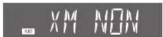
XM ID is communication fails, Press [MODE] to another mode.
Preliminary Steps
Check and take steps as described in the tables below.
If You Suspect Something Wrong
Immediately switch the power off.
Disconnect the power connector and check that there is neither smoke nor heat from the unit before asking for repairs. Never try to repair the unit by yourself because it is dangerous to do so.
Cautions:
- Do not use the unit if it malfunctions or if there is something wrong.
- Do not use the unit in irregular condition, for example, without sound, or with smoke or foul smell, which can cause ignition or electric shock. Immediately stop using it and call the store where you purchased it.
Troubleshooting Tips
Common
Trouble
No power.
No sound.
Noise.

Vehicle's ignition switch is not on.
→ Turn your vehicle's ignition switch to ACC or ON.
Cables are not correctly connected.
→ Connect cables correctly.
Battery cable is not correctly connected.
→ Connect the battery cable to the terminal that is always active.
Power connector is not correctly connected.
→ Connect the power connector to your vehicle's ACC source.
Grounding wire is not correctly connected.
→ Connect the grounding wire to a metal part of the vehicle.
Mute is set to ON.
→ Set it to OFF.
Cables are not correctly connected.
→ Connect cables correctly.
The ground lead is not connected properly.
→ Connect the ground lead properly.
XM Control
Trouble
Antenna
No singl
off air
No info
XM non
Cause/Step
Antenna no connection
→ Check the XM receiver's antenna.
No XM signal
→ select a channel which can be received.
No chanel service
→ select a channel which can be received.
The original channel cannot receive signal.
→ select a channel which can be received.
Do not connect the XM receiver completely.
→ Check the XM receiver's connections.
Troubleshooting (Continued)
Radio
Trouble
Much noise in FM stereo and monaural broadcasts.
Preset station is reset.
Cause/Step
The antenna ground lead is not connected properly.
→ Connect the antenna ground lead properly.
The radio antenna is not extended enough.
→ Extend fully the radio antenna.
Battery cable is not correctly connected.
→ Connect the battery cable to the terminal that is always active.
□ Cassette Tape
Trouble
No sound.
Tape sound quality is poor.
High tones are improperly emphasized.
Reproduction of high tones is poor.
Wow and flutter level is very high.
Cause/Step
Blank tape is inserted in the unit.
→ Insert recorded tape into the unit.
Heads are dirty.
→ Clean heads. (See page 12)
Poor quality tape.
→ Use better quality tape.
Dolby B NR tape plays with Dolby B NR off.
→ Set Dolby B NR to ON.
Metal type tape plays with normal mode.
→ Change Normal mode to Metal mode.
Non-Dolby B NR tape plays with Dolby B NR on.
→ Set Dolby B NR to OFF.
Normal type tape plays with Metal mode.
→ Change Metal mode to Normal mode.
Heads are magnetized.
→ Demagnetize heads. (Ask a service representative for advice.)
Tape running mechanism is dirty or out of order.
→ Clean tape running mechanism, or repair it. (Ask a service representative for advice.)
Sound Setting
Trouble
No sound from left, right, front, or rear speaker.
Left and right sounds are reversed in stereo listening.
Cause/Step
Left and right balance, or front and rear balance is off on one side.
→ Adjust balance/fader setting as appropriate.
Cables are not correctly connected.
→ Connect the cables correctly.
The right speaker wire is connected to the left speaker and the left speaker wire to the right speaker.
→ Connect the speaker wires to the correct ones.
Caution: Please follow the instructions given below. Failure to do so will cause damage to the unit and speakers.

- Use ungrounded speaker only.
- The maximum speaker input should be 37 W or more. (If used with the optional power amplifier, the speaker input should be higher than the maximum amplifier output.)
- The speaker impedance should be 4 - 8 Ω.
- This unit uses the BTCL circuit, so each speaker should be connected separately using parallel vinyl insulated cords.
- The speaker cords and the power amplifier unit should be kept away (about 30 cm apart) from the antenna and antenna extension cord.


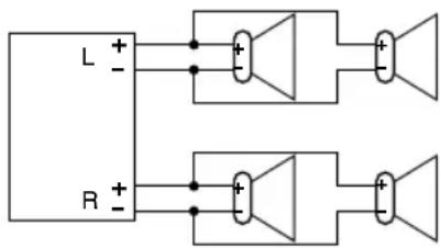
- Never connect the speaker cord to the body of the car.
- Do not use a 3-wire type speaker system having a common earth lead.
- Do not connect more than one speaker to one set of speaker leads.
Product Servicing
If the suggestions in the charts do not solve the problem, we recommend that you take it to your nearest authorized Panasonic Servicenter. The product should be serviced only by a qualified technician.
Maintenance
Your product is designed and manufactured to ensure the minimum of maintenance. Use a soft cloth for routine exterior cleaning. Never use benzine, thinner, or other solvents.
Caution
This product is designed without a fuse inside due to fuses already exist in your vehicle. We would recommend to use fuses of the specified rating (10 A). Using fuses that exceed the prescribed capacity could cause this product to start smoking, ignite or other malfunction.
If your vehicle is without the fuse or a circuit braker to protect this unit, please your dealer add the specified fuse 10 A or a circuit breaker at the BATTERY lead of your vehicle's harness. please see page 26 to find out where "BATTERY + 12 V" is for your dealer adding the fuse or the circuit breaker.

WARNING
☐ This installation information is designed for experienced installers and is not intended for non-technical individuals. It does not contain warnings or cautions of potential dangers involved in attempting to install this product.
Any attempt to install this product in a vehicle by anyone other than a qualified installer could cause damage to the electrical system and could result in serious personal injury or death.
☐ If your vehicle is equipped with air bag and/or anti-theft systems, specific procedures may be required for connection and disconnection of the battery to install this product. Before attempting installation of this electronic component, contact your vehicle dealer or manufacturer to determine the required procedure and strictly follow their instructions.
FAILURE TO FOLLOW THE PROCEDURE MAY RESULT IN THE UNINTENDED DEPLOYMENT OF AIR BAGS OR ACTIVATION OF THE ANTI-THEFT SYSTEM RESULTING IN DAMAGE TO THE VEHICLE AND PERSONAL INJURY.
Overview
This product should be installed by a professional.
However, if you plan to install this product yourself, your first step is to decide where to install it. The instructions in these pages will guide you through the remaining steps:
(Please refer to the "WARNING" statement above.)
- Identify and label the car wires.
- Connect the car wires to the wires of the power connector.
• Install the unit in the dashboard. - Check the operation of the unit.
If you encounter problems, please consult your nearest professional installer.
Caution: This unit operates with a 12 V DC negative ground auto battery system only. Do not attempt to use it in any other system. Doing so could cause serious damage.
Before you begin installation, look for the items which are packed with your unit.
- Warranty Card...Fill this out promptly.
• Panasonic Servicenter List for Service Directory
...Keep for future reference in case the product needs servicing.
- Installation Hardware...Needed for in-dash installation.
□ Dashboard Specifications
Thickness Min. 316 " (4.75 mm)
Max. 132 (5.56 mm)

□ Preparation □ Installation Hardware
Warning: If your vehicle is equipped with air bag and/or anti-theft systems, specific procedures may be required for connection and disconnection of the battery to install this product.
Before attempting installation of this electronic component, contact your vehicle dealer or manufacturer to determine the required procedure and strictly follow their instructions.
FAILURE TO FOLLOW THE PROCEDURE MAY RESULT IN THE UNINTENDED DEPLOYMENT OF AIR BAGS OR ACTIVATION OF THE ANTI-THEFT SYSTEM RESULTING IN DAMAGE TO THE VEHICLE AND PERSONAL INJURY.
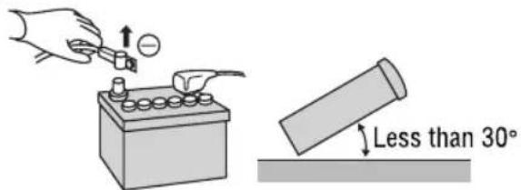
- Disconnect the cable from the negative battery terminal (see warning and caution below).
- Remove Mounting Collar ① from the main unit temporarily, which are already mounted at shipment.*
Caution: Various settings that have been stored in the memory in other on-board equipment (vehicle navigation etc.) may be lost if the battery terminals are disconnected.
Therefore, we recommend to make a record of or to back up the settings before disconnecting the terminals.
After completing installation of the main unit, set the equipment again according to the record.
- Unit should be installed in a horizontal position with the front end up at a convenient angle, but not more than 30irc .
□ Dashboard Installation
Installation Opening
This unit can be installed in any dashboard having an opening as shown below. The dashboard should be 3/16" (4.75 mm) - 7/32" (5.56 mm) thick in order to be able to support the unit.

| Q'tylt | |||
| 1 |  | 1Mo | |
| 2 | Plain washer (5mmø) | [32Y2] | 2 |
| 3 | Spring Washer (5mmø) |  | 2 |
| 4 | Hex. Nut (5mmø) | [###] | 2 |
| 5 | Rear Support Strap |  | 1 |
| 6 | Hex. Bolt(5mmø × 25 mm) |  | 1 |
| 7 | Toothed Lock Washer(5mmø) |  | 1 |
| 8 | Removal Tool(U-shaped) | 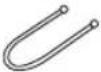 | 2 |
| 9 | Antenna Connector |  | 1 |
(a) Using the rear support strap ⑤

(b) Using the rubber cushion (option)

Cautions:
- We strongly recommend that you wear gloves for installation work to protect yourself from injuries.
- When bending the mounting tab of the mounting collar with a screwdriver, be careful not to injure your hands and fingers.
First complete the electrical connections, and then check them for correctness.(→ page 26)
The included Mounting Collar ① is designed specially for this unit. Do not use it to attach any other model.


Establish the rear connection of the unit.
After fixing Power Connector, fix the rear of the unit to the vehicle body by either method (a) or (b) shown in the previous page.

After installation reconnect the negative (−) battery terminal.
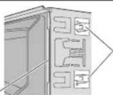
Engage the Mounting Springs (※) in the mounting holes of the Mounting Collar ① firmly.
Mounting Spring
natural_image
Diagram of a door frame with internal compartments and structural details (no text or symbols)Mounting Hole

natural_image
Illustration of a hand using a tool to adjust or install a battery with a pointer (no text or symbols present)To Remove the Unit from the vehicle's dashboard
Insert each Removal Tool ⑧ and pull.

natural_image
Pure technical diagram of a mechanical component with no text, numbers, or symbols⑧ Removal Tool (U-shaped)
Note: Do not lose Removal Tools. They will be needed to remove the unit from the vehicle's dashboard.
Electrical Connections
Cautions:
- This wiring information is for experienced technical individual, for safety reason, please your dealer wire this connection.
- This product is designed to operate with a 12 V DC, negative ground battery system.
- To prevent damage to the unit, be sure to follow the connection diagram below.
- Do not insert the power connector into the unit until the wiring is completed.
- Be sure to insulate any exposed wires from a possible short-circuit from the vehicle chassis. Bundle all cables and keep cable terminals free from touching any metal parts.
- Remember, if your vehicle has a drive computer or a navigation computer, the data of its memory maybe erased when the battery terminals are disconnected.
□ Wiring Diagram

flowchart
graph TD
    A["Antenna"] --> B["CQ-4330U"]
    B --> C["Power Connector"]
    C --> D["AC"]
    C --> E["Battery"]
    D --> F["Ground Lead (Connect to a clean, bare metallic part of your vehicle)"]
    E --> G["Battery Lead (Connect to vehicle battery)"]
    B --> H["Antenna Connector"]
    H --> I["Power Connector"]
    I --> J["Ground"]
    I --> K["Battery"]
    style A fill:#f9f,stroke:#333
    style B fill:#ccf,stroke:#333
    style C fill:#cfc,stroke:#333
    style D fill:#fcc,stroke:#333
    style E fill:#cff,stroke:#333
    style F fill:#ffc,stroke:#333
    style G fill:#ffc,stroke:#333
    style H fill:#cfc,stroke:#333
    style I fill:#cfc,stroke:#333
    style J fill:#fcc,stroke:#333
    subgraph Power Connector Details
        K1["ACC (Red)"]
        K2["Ground (Black)"]
        K3["Battery (Yellow)"]
        K4["Ground Lead (Connect to a clean, bare metallic part of your vehicle)"]
        K5[" Battery Lead (Connect to vehicle battery)"]
    end
    subgraph Note Details
        L1["NO. FUNCTION NO. FUNCTION"]
        M1["1 B A TTERY +12 V 9 REAR SP R (-)"]
        N1["2 GROUND 10 REAR SP R (+)"]
        O1["3 ——"] --> P1["11 FRONT SP R (-)"]
        Q1["4 ——"] --> R1["12 FRONT SP R (+)"]
        S1["5 ——"] --> T1["13 FRONT SP L (-)"]
        U1["6 POWER +12 V ACC 14 FRONT SP L (+)"]
        V1["7 ——"] --> W1["15 REAR SP L (-)"]
        X1["8 ——"] --> Y1["16 REAR SP L (+)"]
    end
□ Upgrading the system (connect a XM receiver)
Note:
For wiring, carefully read the operation instructions for the devices connected.

flowchart
graph TD
    A["XM ANT"] --> B["XM RECEIVER (XM-RVR-D-001)"]
    B --> C["8P DIN (Male)"]
    B --> D["RCA (Red) R"]
    B --> E["RCA (White) L"]
    B --> F["FM out"]
    B --> G["controller' head unit"]
    B --> H["audio out"]
    B --> I["power"]
    B --> J["antenna"]
    C --> K["CQ-4330U"]
    D --> K
    E --> K
    F --> K
    G --> K
    H --> K
    I --> K
    J --> K
    K --> L["XM control connector (2P connector)"]
    K --> M["XM control connector (10P connector)"]
    style A fill:#f9f,stroke:#333
    style B fill:#ccf,stroke:#333
    style C fill:#cfc,stroke:#333
    style D fill:#fcc,stroke:#333
    style E fill:#cff,stroke:#333
    style F fill:#ffc,stroke:#333
    style G fill:#cfc,stroke:#333
    style H fill:#fcc,stroke:#333
    style I fill:#ffc,stroke:#333
    style J fill:#fcc,stroke:#333
    style K fill:#cfc,stroke:#333
    style L fill:#fcc,stroke:#333
□ Upgrading the system ( connect a CD changer )
Note:
For wiring, carefully read the operation instructions for the devices connected.

Extension Cable for connecting the unit and CD changer.
※The Extension cable does not come along with the unit, if need, please consult your dealer.
General
Power Supply: 12 V DC (11 V-16 V) test Voltage 14.4 V, Negative ground
Current consumption: Less than 2.5 A (tape mode, 0.5 W 4-speaker)
Maximum Power Output: 37 W × 4 channels at 400 Hz, Volume Control maximum
Tone adjustment range:
Bass: ± 12 dB at 100 Hz
Treble: ± 12 dB at 10 kHz
Power Output: 18 W per channel into 4 ohms, 40 to 30 000 Hz at 3 % THD
Suitable Speaker Impedance: 4-8 Ω
Dimensions (W × H × D): 7" × 1-15/16" × 6-1/10" (178 × 50 × 160 mm)
Weight: 3 lbs. 12 oz (1.7k g)
FM Stereo Radio
Frequency Range: 87.9-107.9 MHz
Useable Sensitivity: 12 dBf. (1.1 μV/75 Ω, S/N 30 dB)
50 dB Quieting Sensitivity: 17 dBf. (1.8 μV/75 Ω)
Frequency Response: 30-15 000 Hz ±3 dB
Alternate Channel Selectivity: 75 dB
Stereo Separation: 35 dB at 1 kHz
Signal/Noise Ratio: 70 dB (Mono)
□ AM Radio
Frequency range: 530 kHz–1 710 kHz
Usable sensitivity: 28 dB/μV (25 μV, S/N 20 dB)
□ Weather Band Radio
Frequency Range: 162.40-162.55 MHz
Useable Sensitivity: 3 dB/μV (S/N 20 dB)
Signal/Noise Ratio (40 dB/ µ V): 50 dB
□ Tape Player
Reproduction System: 4-track, 2-program stereo
Tape Speed: 1-7/8"/sec (4.76 cm/sec)
FF/REW Time: Less than 110 sec (C-60)
Frequency Response: 35-14 000 Hz ±3 dB
Wow and Flutter: 0.12 % (WRMS)
signal/Noise Ratio: 52 dB (Dolby NR on: 62 dB)
Above specifications comply with EIA standards.
Note: Specifications and design are subject to modification without notice due to improvements in technology.
Dobly noise reduction manufactured under license from Dolby Laboratories Licensing Corporation.
"DOLBY" and the double-D symbol □□ are trademarks of Dolby Laboratories Licensing Corporation.
Panasonic Consumer Electronics
Company, Division of Matsushita
Electric Corporation of America
One Panasonic Way, Secaucus,
New Jersey 07094
- Safety Information
- WARNING:
- CAUTION:
- The following applies only in the U.S.A.
- Part 15 of the FCC Rules
- FCC Warning:
- NOTICE:
- □ Use this product safely
- When Driving
- When Car Washing
- When Parked
- Use the Proper Power Supply
- Protect the Tape Mechanism
- What is XM Satellite Radio?
- Accessories
- Contents
- Power and Sound Controls
- Power and Sound Controls (Continued)
- Audio Modes
- (Bass/Treble/Balance/Fader)
- Illumination Switching
- Selecting the Clock Display
- Time Setting
- Hours
- Minutes
- Time Reset
- Initial Alarm Time
- Alarm Time Setting
- Alarm Time Reset
- Alarm Operation
- Turning off the Alarm Sound
- Alarm output Volume Selection
- Cautions:
- Seek Tuning
- Preset Station Setting
- ① Band
- ② Auto Preset Memory (APM)
- Manual Preset Memory
- Preset Station Calling
- Tuning in a Weather Band Station
- Weather Band Stations
- Cassette Tape Player
- Loading a Cassette
- Notes on Cassette Tapes
- Tape Slack:
- Ejecting the Tape
- Notes:
- Play Side Change
- Cassette Head Cleaning Warning
- Rewind and Fast Forward
- Metal Tape Mode
- Dolby B Noise Reduction
- Tape Program Search (TPS) Operation
- Blank Skip
- Repeat Play
- CD Changer Control
- ① CD Changer mode
- ② Disc Selection
- ③ Track Selection
- Track Search
- Note:
- Scan Play (Tracks)
- Scan Play (Discs)
- Repeat Play (Tracks)
- Repeat Play (Discs)
- Random Play (Tracks)
- Random Play (Discs)
- Error Display Messages
- Preparation:
- Category Priority Setting and Selecting
- Preset memory Calling
- Display Change
- XM ID Confirmation
- Error display
- Preliminary Steps
- If You Suspect Something Wrong
- Troubleshooting Tips
- Common
- Trouble
- XM Control
- Cause/Step
- Troubleshooting (Continued)
- Radio
- □ Cassette Tape
- Sound Setting
- Product Servicing
- Maintenance
- Caution
- WARNING
- Overview
- □ Dashboard Specifications
- □ Preparation □ Installation Hardware
- □ Dashboard Installation
- Installation Opening
- Using the rear support strap ⑤
- Using the rubber cushion (option)
- To Remove the Unit from the vehicle's dashboard
- Electrical Connections
- □ Upgrading the system (connect a XM receiver)
- □ Upgrading the system ( connect a CD changer )
- General
- FM Stereo Radio
- □ AM Radio
- □ Weather Band Radio
- □ Tape Player
Brand : PANASONIC
Model : CQ-4330U
Category : Car Radio