
IMG-110T - Modbus Gateway Planet - Free user manual and instructions
Find the device manual for free IMG-110T Planet in PDF.


| Product Type | Industrial 1-port RS422/485 Modbus Gateway |
| Brand | Planet |
| Model | IMG-110T |
| Dimensions (W x D x H) | 69 x 100 x 22 mm |
| Weight | 238 g |
| Power Input | 9 to 48V DC via 2-contact terminal block |
| Power Consumption | 1.1 watts (max) |
| Serial Interface | 1 RS422/RS485 port, 5-contact terminal block, surge protection 1KV |
| Ethernet Interface | 1 10/100BASE-TX RJ45 port, auto-MDI/MDI-X |
| Baud Rate | 300 bps to 115200 bps |
| Data Bits | 7 or 8 |
| Parity | Odd, Even, None, Space, Mark |
| Stop Bits | 1 or 2 |
| Flow Control | Hardware or None |
| Operating Temperature | -40°C to 75°C |
| Storage Temperature | -40°C to 75°C |
| Humidity | 5% to 95% (non-condensing) |
| Protocol Support | Modbus TCP, Modbus RTU, Modbus ASCII, IP, ARP, DHCP, DNS |
| Management Methods | Web interface, Telnet, PLANET Modbus Gateway Utility, PLANET Smart Discovery Utility |
| LED Indicators | Power (green), Link/Activity (green), TX (green), RX (green) |
| Mounting | Wall-mount kit included |
| Enclosure Material | IP40-rated metal case |
| Regulatory Compliance | FCC Part 15 Class B, CE, WEEE |
Frequently Asked Questions - IMG-110T Planet
User questions about IMG-110T Planet
0 question about this device. Answer the ones you know or ask your own.
Ask a new question about this device
Download the instructions for your Modbus Gateway in PDF format for free! Find your manual IMG-110T - Planet and take your electronic device back in hand. On this page are published all the documents necessary for the use of your device. IMG-110T by Planet.
USER MANUAL IMG-110T Planet
Trademarks
Copyright © PLANET Technology Corp. 2017.
Contents are subject to change without prior notice.
PLANET is a registered trademark of PLANET Technology Corp. All other trademarks belong to their respective owners.
Disclaimer
PLANET Technology does not warrant that the hardware will work properly in all environments and applications, and makes no warranty and representation, either implied or expressed, with respect to the quality, performance, merchantability, or fitness for a particular purpose. PLANET has made every effort to ensure that this User's Manual is accurate; PLANET disclaims liability for any inaccuracies or omissions that may have occurred.
Information in this User's Manual is subject to change without notice and does not represent a commitment on the part of PLANET. PLANET assumes no responsibility for any inaccuracies that may be contained in this User's Manual. PLANET makes no commitment to update or keep current the information in this User's Manual, and reserves the right to make improvements to this User's Manual and/or to the products described in this User's Manual, at any time without notice.
If you find information in this manual that is incorrect, misleading, or incomplete, we would appreciate your comments and suggestions.
FCC Warning
This equipment has been tested and found to comply with the limits for a Class B digital device, pursuant to Part 15 of the FCC Rules. These limits are designed to provide reasonable protection against harmful interference when the equipment is operated in a commercial environment. This equipment can radiate radio frequency energy and, if not installed and used in accordance with the instructions, it may cause harmful interference to radio communications. Operation of this equipment in a residential area is likely to cause harmful interference in which case the user will be required to correct the interference at his own expense.
CE Mark Warning
This is a Class B product. In a domestic environment, this product may cause radio interference, in which case the user may be required to take adequate measures.
Energy Saving Note of the Device
This power required device does not support Standby mode operation. For energy saving, please remove the power cable to disconnect the device from the power circuit. In view of saving the energy and reducing the unnecessary power consumption, it is strongly suggested to remove the power connection for the device if this device is not intended to be active.
WEEE Warning

To avoid the potential effects on the environment and human health as a result of the presence of hazardous substances in electrical and electronic equipment, end users of electrical and electronic equipment should understand the meaning of the crossed-out wheeled bin symbol. Do not dispose of WEEE as unsorted municipal waste and have to collect such WEEE separately.
Revision
PLANET Industrial 1-port RS422/485 Modbus Gateway User's Manual
FOR MODEL: IMG-110T
REVISION: 1.0 (May, 2017)
Part No.: 2081-AH1230-000
TABLE OF CONTENTS
1. INTRODUCTION ....5
1.1 PACKAGE CONTENTS 5
1.2 HOW TO USE THIS MANUAL....5
1.3 PRODUCT DESCRIPTION....6
1.4 APPLICATIONS .... 7
1.5 PRODUCT FEATURES 9
1.6 PRODUCT SPECIFICATIONS.... 10
2. HARDWARE INSTALLATION ....12
2.1 HARDWARE DESCRIPTION 12
2.1.1 Product Layout....12
2.1.2 LED Indicators.... 13
2.1.3 2-Contact Terminal Block Pin Define .... 14
2.1.4 5-Contact Terminal Block Pin Define .... 14
2.1.5 Hardware DIP Switch for Reset to Default 15
3. INDUSTRIAL MODBUS GATEWAY MANAGEMENT ....16
3.1 OVERVIEW.... 16
3.2 REQUIREMENTS 17
3.3 MANAGEMENT METHODS.... 17
3.3.1 Web Management Interface 17
3.3.2 Login the Industrial Modbus Gateway Web Interface....18
3.3.3 Remote IP-based Telnet Interface 19
3.3.4 Login the Industrial Modbus Gateway Telnet Interface 20
3.4 PLANET SMART DISCOVERY UTILITY 21
3.5 PLANET MODBUS GATEWAY UTILITY.... 23
3.5.1 Installing PLANET Modbus Gateway Utility....23
3.5.2 PLANET Modbus Gateway Utility Menu Bar 28
3.5.3 PLANET Modbus Gateway Utility Shortcut Menu Bar 34
3.5.4 PLANET Modbus Gateway Utility Device Function....38
4. WEB MANAGEMENT ....43
4.1 WEB MAIN PAGE 43
4.2 OVERVIEW.... 44
4.3 NETWORK SETTINGS.... 45
4.4 SERIAL SETTINGS 47
4.4.1 COM Settings....47
4.4.2 COM Information....49
4.5 MODBUS SETTINGS.... 50
4.5.1 Modbus Parameters....50
4.5.2 Slave ID....52
4.6 STATE MONITORING....58
4.6.1 COM State 58
4.7 ACCESS CONTROL....59
4.7.1 Device Security 59
4.7.2 IP Filtering....60
4.7.3 MAC Filtering 61
4.7.4 User Management....62
4.8 SYSTEM MANAGEMENT 63
4.8.1 System Information 63
4.8.2 System File 64
4.8.3 Logout & Reboot 65
5. COMMAND LINE INTERFACE....66
5.1 ACCESSING THE CLI 66
5.2 TELNET LOGIN 66
6. COMMAND LINE MODE....67
APPENDIX A....70
A.1 DEVICE'S RJ45 PIN ASSIGNMENTS....70
A.2 RJ45 CABLE PIN ASSIGNMENT 70
1. INTRODUCTION
Thank you for purchasing PLANET Industrial 1-port RS422/485 Modbus Gateway, IMG-110T. The term "Industrial Modbus Gateway" mentioned in this user's manual refers to the IMG-110T.
1.1 Package Contents
Open the box of the Industrial Modbus Gateway and carefully unpack it. The box should contain the following items:
■ The Industrial Modbus Gateway x 1

■ Quick Installation Guide x 1

■ User's Manual CD x 1

If any of these are missing or damaged, please contact your dealer immediately, if possible, retain the carton including the original packing material, and use them again to repack the product in case there is a need to return it to us for repair.
1.2 How to Use This Manual
This Industrial Modbus Gateway User Manual is structured as follows:
Section 2, HARDWARE INSTALLATION
The section explains the functions of the Industrial Modbus Gateway and how to physically install the Industrial Modbus Gateway.
Section 3, INDUSTRIAL MODBUS GATEWAY MANAGEMENT
The section contains the information about the software function of the Industrial Modbus Gateway, and also explains the PLANET Modbus Gateway utility and how to use the Industrial Modbus Gateway.
Section 4, WEB MANAGEMENT
The section explains how to manage the Industrial Modbus Gateway by Web interface.
Section 5, COMMAND LINE INTERFACE
The section describes how to use the Command Line interface (CLI).
Section 6, COMMAND LINE MODE
The section explains how to manage the Industrial Modbus Gateway by Command Line interface.
Appendix A
The section contains cable information of the Industrial Modbus Gateway.
1.3 Product Description
Economic Solution for Industrial Modbus TCP/RTU/ASCII Network Integration
PLANET has added the Industrial Modbus TCP/IP Protocol to industrial management level products to provide its easily-integrated industrial management level products with SCADA/HMI system and other data acquisition systems in factory floors. Moreover, the industrial IT SNMP network is upgraded to the industrial automation Modbus TCP/IP network. PLANET industrial management level products with the Modbus TCP/IP Protocol offer flexible network connectivity solution for industrial automation environment. To complete the industrial automation environment application solution, PLANET has announced a first industrial level 1-port RS422/485 Modbus Gateway -- IMG-110T, a bridge that converts between Modbus TCP/IP Protocol and Modbus RTU/ASCII Protocol. It features a wide operating temperature range from -40 to 75 degrees C and a compact but rugged IP40 metal housing.
Modbus TCP/IP for Modbus RTU/ASCII Network Environment Deployment
The Industrial Modbus Gateway can be a conversion bridge between the industrial equipment with the Modbus RTU/ASCII Protocol and the administrator workstations that run the Modbus TCP/IP Protocol. The RS422/485 serial interface of the Industrial Modbus Gateway provides the Modbus RTU/ASCII operation mode and various baud rate options to meet the demand of integration between the Modbus TCP/IP Protocol, Modbus RTU Master/Slave Protocol and Modbus ASCII Master/Slave Protocol.
The advantage of having the Industrial Modbus Gateway is to assist users to build an industrial environment between the Modbus TCP/IP Protocol and the Modbus RTU/ASCII Protocol easily, thus offering an application solution to the industrial control equipment without Ethernet ports and the industrial control equipment can only control through an industrial PC workstation or industrial control panel.
In addition, the effective integration solution of Modbus Ethernet devices, Modbus serial equipment or multi Modbus master / slave in an industrial hybrid network brings the following:
■ Master mode supports up to 32 slave TCP connection requests
■ Slave mode supports up to 16 TCP master connections
Remote Management
The Industrial Modbus Gateway makes the connected industrial Modbus RTU/ASCII equipment become IP-based facilities and is able to connect to the Modbus TCP/IP network via its R422/485 serial interface and 10/100BASE-TX RJ45 Ethernet port. It provides a remote web management and telnet Interface for efficient remote network management. The Industrial Modbus Gateway also provides PLANET Modbus Gateway utility tool and supports PLANET Smart Discovery utility to help network administrator to easily get the current IP subnet address information or change the IP subnet address setting of the Industrial Modbus Gateway.
Modbus Serial Port State Monitoring
The Industrial Modbus Gateway shows the details of the total bytes transmitted and received on the RS422/485 serial interface, and the detailed total number of frames transmitted and received on the remote web/telnet management interface. This function allows network administrator to check the status and statistics of the Industrial Modbus Gateway via the single RS422/485 serial interface.
Stable Performance in Hardened Environment Design
The Industrial Modbus Gateway provides a high level of immunity against electromagnetic interference and heavy electrical surges which are usually found on plant floors or in curb-side traffic control cabinets. Its operating temperature ranging from -40 to 75 degrees C allows the Industrial Modbus Gateway to be placed in almost any difficult environment.
The Industrial Modbus Gateway is equipped with a compact IP40-rated metal case that allows wall mounting for efficient use of cabinet space. The Industrial Modbus Gateway also provides an integrated power supply source with wide-ranging voltages (9 to 48V DC) ideally suitable for worldwide operation with high availability applications.
1.4 Applications
RTU/ASCII Master to Multi Modbus TCP/IP Slaves
The Industrial Modbus Gateway can act as a bridge between the industrial RTU/ASCII master equipment and the multi-industrial TCP/IP slave equipment in a Modbus TCP/IP networking environment to control multi-industrial TCP/IP slave equipment via the industrial RTU/ASCII master equipment.
RTU/ASCII Master to Multi Modbus TCP/IP Slaves
![graph TD A["HMI RTU/ASCII Master"] -->|RS485| B["IMG-110T Modbus Gateway"] C["DCS"] --> D["Modbus TCP/IP Slave Devices"] E["DCS"] --> F["Modbus TCP/IP Slave Devices"] style A fill:#f9f,stroke:#333 style B fill:#ccf,stroke:#333 style C fill:#cfc,stroke:#333 style D fill:#fcc,stroke:#333 style E fill:…](/content/2026/05/1081726/images/df2b51e8f35f28243396b0b1ad38ce9f671977a5a0a911e1c90c0cf02504dc16.jpg)
Figure 1-1: RTU/ASCII Master to Multi Modbus TCP/IP Slaves Application
Multi Modbus TCP/IP Master to RTU/ASCII Slaves
The Industrial Modbus Gateway can operate as a bridge between the multi-industrial TCP/IP master equipment and the industrial RTU/ASCII slave equipment in a Modbus TCP/IP networking environment to control the industrial RTU/ASCII slave equipment via the multi-industrial TCP/IP master equipment.
Multi Modbus TCP/IP Master to RTU/ASCII Slaves
![graph TD A["Host Computer"] --> B["Modbus TCP Master"] C["Modbus TCP Master Devices"] --> D["PLC"] B --> E["IMG-110T Modbus Gateway"] D --> E E --> F["Flow Meters(Drive)"] F --> G["IC485"] E --> H["IMG-110T Modbus Gateway"] H --> I["Loop Controller, Power Measurement (up to 32 Devices)"] H --> J["IC…](/content/2026/05/1081726/images/aef6e9a7038b6b333b508950a78c482081e380fd9e37d796eab965c3c7c0a4c7.jpg)
Figure 1-2: Multi Modbus TCP/IP Master to RTU/ASCII Slaves Application
1.5 Product Features
Serial Interface
■ One RS422/485 port with 5-contact terminal block
■ Cost effective for RS422/RS485 to Fast Ethernet 10/100BASE-TX application
■ Supports 4-wire RS422 or 2-wire RS485 with 5-contact terminal block operation
300bps\~115200bps baud rate and non-blocking communication
Ethernet Interface
■ Complies with IEEE 802.3, IEEE 802.3u 10/100BASE-TX standard
■ Supports 10/100BASE-TX RJ45 port with distance up to 100m
▶ Serial Operation Modes
■ Software Protocol supports Modbus TCP, Modbus RTU, Modbus ASCII, IP, ARP, DHCP and DNS
■ Supports RTU Master, RTU Slave, ASCII Master, and ASCII Slave four serial operation modes via management interface
■ Master mode supports 32 slave TCP connection requests
■ Slave mode supports 16 TCP master connections
▶ Management Function
Built-in IP-based Web interface and telnet interface for remote management
■ Supports IP address and MAC address filtering function
■ PLANET Modbus Gateway utility for finding client device on the network and related IP subnet address setting to reset to factory default function
■ PLANET Smart Discovery utility automatically finds the client devices on the network
■ Firmware upgrade/configuration backup and restore via HTTP protocol
Hardware
■ LED indicators for system, network and RS422/585 port diagnostics
■ DIP switch on the upper panel for resetting to factory default
Wall-mount kit
▶ Industrial Case and Installation
■ Wall mount-type IP40 metal case
The 2-contact terminal block connector on the top panel of Industrial Modbus Gateway is used for DC power input (9-48V)
-40 to 75 degrees C operating temperature
1.6 Product Specifications
| Model | IMG-110T |
| Serial Port | |
| Interface | RS422/ RS485 x 1 |
| Connector | 5-contact terminal block for RS422/RS485 |
| Surge Protection 1KV | |
| Baud Rate (Data Rate) | 300bps to 115200bps |
| Data Bits | 7, 8 |
| Parity Type | Odd, Even, None, Space, Mark |
| Stop Bit | 1, 2 |
| Flow Control | H/W, None |
| Signals | RS422 : Tx+, Tx-, GND, Rx+, Rx-RS485: Data A (+), GND, Data B (-) |
| Distance | RS422/RS485 for 20m transfer distance |
| Operation Mode | RTU Master/RTU Slave/ASCII Master/ASCII SlaveMaster mode: Supports up to 32 slave TCP connection requestsSlave mode: Supports up to 16 TCP master connection requests |
| Ethernet Port | |
| Standard | IEEE 802.310BASE-T standardIEEE 802.3u 100BASE-TX standardIEEE 802.3x full-duplex flow control |
| Connector | RJ45 |
| Distance | 100 meters |
| Hardware | |
| Copper Port | 10/100BASE-T RJ45 TP x1, auto-MDI/MDI-X, auto-negotiation |
| Serial Port | RS422/RS485 x 1 |
| DIP Switch | Reset system to factory default |
| LED Indicators | System: Power x 110/100BASE-TX Port: Link/Active x 1RS422/RS485 Serial Port: TX (Transmit) x 1, RX (Receive) x 1 |
| Dimensions (W x D x H) | 69 x 100 x 22 mm |
| Weight | 238g |
| Power Input Connector | 2-contact terminal block connector DC power (9-48V)* |
| Power Consumption | 1.1 watts / 3.7BTU (max.) |
| Installation | Wall-mount kit |
| Mechanical | Metal |
| Management | |
| Management | Remote Web ManagementRemote Telnet ManagementPLANET Modbus Gateway UtilityPLANET Smart Discovery Utility |
| Operation Mode | RTU MasterRTU SlaveASCII MasterASCII Slave |
| Standards Conformance | |
| Standards Compliance | IEEE 802.310BASE-T standardIEEE 802.3u 100BASE-TX standardIEEE 802.3x full-duplex flow controlEIA/TIA RS422/485 |
| Regulatory Compliance | FCC Part 15 Class B, CE |
| Stability Testing | IEC60068-2-32 (free fall)IEC60068-2-27 (shock)IEC60068-2-6 (vibration) |
| Environment | |
| Temperature | Operating: -40~75 degrees CStorage: -40~75 degrees C |
| Humidity | Operating: 5~95% (non-condensing)Storage: 5~95% (non-condensing) |
*: Please follow the DC power input symbol on the front panel of the Industrial Modbus Gateway -- insert positive DC power wire into V+, and negative DC power wire into V-. Otherwise, it will damage the device.
2. HARDWARE INSTALLATION
This section describes the hardware features and installation of the Industrial Modbus Gateway's components on the desktop or shelf. For easier management and control of the Industrial Modbus Gateway, familiarize yourself with its display indicators, and ports. Front panel illustrations in this chapter display the unit LED indicators. Before connecting any network device to the Industrial Serial Converter, please read this chapter completely.
2.1 Hardware Description
2.1.1 Product Layout
Figure 2-1 shows the diagram of the Industrial Modbus Gateway, and the wall-mount kit for wall mounting.
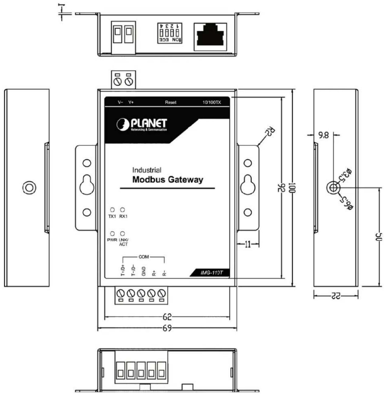
Figure 2-1: Industrial Modbus Gateway
Figure 2-2 shows the front panel of the Industrial Modbus Gateway.
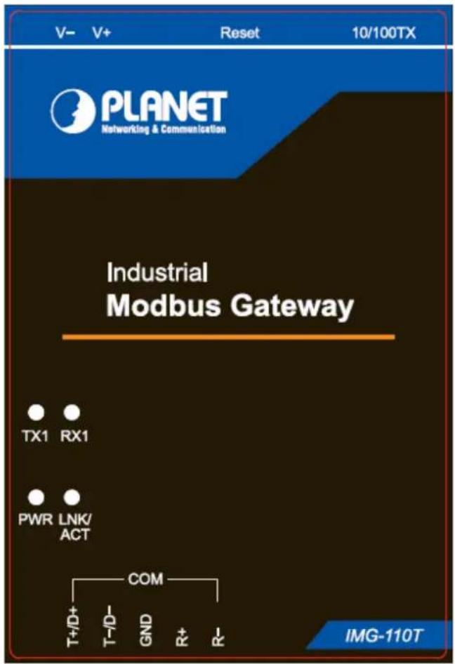
Figure 2-2: Industrial Modbus Gateway Front Panel
2.1.2 LED Indicators
LED Definition
System
| LED Color Function | ||
| Power | Green | Lights to indicate the system has power. |
10/100BASE-TX Interface
| LED Color Function | |||
| LNK/ACT Green | Lights: | To indicate the link through that port is successfully established. | |
| Blinks: | To indicate that the IMG-110T is actively sending or receiving data over that port. | ||
RS422/RS485 Serial Port
| LED Color Function | |||
| TX1 | Green | Blinks: | To indicate that the IMG-110T is actively transmitting data over that port. |
| RX1 | Green | Blinks: | To indicate that the IMG-110T is actively receiving data over that port. |
2.1.3 2-Contact Terminal Block Pin Define
■ Wiring the Power Inputs:
The 2-contact terminal block connector on the top panel of the Industrial Modbus Gateway is used for DC power input and the DC power input range is 9-48V.


1: Please follow the DC power input symbol on the front panel of the Industrial Modbus Gateway -- insert positive DC power wire into V+, and negative DC power wire into V-. Otherwise, it will damage the device.
2: The wire gauge for the terminal block should be in the range between 12 \~ 24 AWG.
2.1.4 5-Contact Terminal Block Pin Define
Serial Port Connection:
The 5-contact terminal block connector on the lower panel of the Industrial Modbus Gateway is used for RS422/485 connections.

| PIN | RS485 PIN Define | RS422 PIN Define |
| 1 | D+ | T+ |
| 2 | D- | T- |
| 3 | GND | GND |
| 4 | -- | R+ |
| 5 | -- | R- |
2.1.5 Hardware DIP Switch for Reset to Default
The upper panel of the Industrial Modbus Gateway consists one 4-bit DIP switch for resetting the system to the factory default mode.
■ Resetting to default through hardware DIP switch:
1: Find the hardware DIP switch that is near the RJ45 port of the Industrial Modbus Gateway.
2: Adjust DIP 2 at the "ON" position and DIPs 1, 3, 4 remain at the original position.
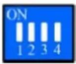
3: After adjusting the DIP switch, please power off and power on the Industrial Modbus Gateway to take effect.

After resetting the Industrial Modbus Gateway with the default IP address, and username and password: admin, please adjust DIP 2 to lower position. Otherwise, the Industrial Modbus Gateway will continue to reset to the factory default mode.
3. INDUSTRIAL MODBUS GATEWAY MANAGEMENT
This chapter describes how to manage the Industrial Modbus Gateway. Sections include:
- Overview
-Requirements - Management Methods
- PLANET Smart Discovery Utility
- PLANET Modbus Gateway Utility
3.1 Overview
This chapter gives an overview of the Industrial Modbus Gateway management. The Industrial Modbus Gateway provides a remote IP-based WEB browser/Telnet interface. Using these interfaces, you can perform various configuration and management activities, including:

Figure 3-1: Industrial Modbus Gateway Web Menu Bar
| List | --List commands name | |
| Help | --List commands name and help info | |
| Quit | --Quit from CLI | |
| Exit | --Exit from current menu | |
| Reboot | --Reboot device | |
| Serial | <dir> | --Enter serial setting menu |
| Security | <dir> | --Enter security setting menu |
| Manage | <dir> | --Enter system manage menu |
| Information | <dir> | --Enter device information menu |
| Modbus | <dir> | --Enter Modbus manage menu |
Figure 3-2: Industrial Modbus Gateway Telnet Menu
Please refer to the following Chapters 4, 5 and 6 for more details.
3.2 Requirements
Ethernet Port Connection
- Workstations running Windows XP/2003/Vista/7/8/2008/10, MAC OS X or later, Linux, UNIX, or other platforms are compatible with TCP/IP protocols.
• Workstations are installed with Ethernet NIC (Network Interface Card)
➢ Network cables -- Use standard network (UTP) cables with RJ45 connectors.
The above PC is installed with Web browser and JAVA runtime environment plug-in.

It is recommended to use Internet Explorer 8.0 or above to access the Industrial Modbus Gateway. If the Web interface of the Industrial Modbus Gateway is not accessible, please turn off the anti-virus software or firewall and then try it again.
3.3 Management Methods
The way to manage the Industrial Modbus Gateway:
- Web Management interface
- Remote IP-based Telnet interface
3.3.1 Web Management Interface
The Industrial Modbus Gateway offers management features that allow users to manage the Industrial Modbus Gateway from anywhere on the network through a standard browser such as Microsoft Internet Explorer. After you set up your IP address for the Industrial Modbus Gateway, you can access the Industrial Modbus Gateway's Web interface applications directly in your Web browser by entering the IP address of the Industrial Modbus Gateway.
![graph LR A["Modbus Gateway"] -->|RJ45/UTP Cable| B["PC/Workstation with Telnet Client 192.168.0.x"]](/content/2026/05/1081726/images/f2ca9f507b33ec8470a36703e482d70890d239d338149082258c596b7c516769.jpg)
Figure 3-3: Web Management Diagram
You can then use your Web browser to list and manage the Industrial Modbus Gateway configuration parameters from one central location. Web Management requires either Microsoft Internet Explorer 8.0 or later, Google Chrome, Safari or Mozilla Firefox 1.5 or later.
3.3.2 Login the Industrial Modbus Gateway Web Interface
The following shows how to start up the Web Management of the Industrial Modbus Gateway. Note the Industrial Modbus Gateway is configured through an Ethernet connection. Please make sure the manager PC must be set to the same IP subnet address.
For example, the default IP address of the Industrial Modbus Gateway is 192.168.0.100, then the manager PC should be set to 192.168.0.x (where x is a number between 1 and 254, except 100) and the default subnet mask is 255.255.255.0.
Logging in to the Industrail Modbus Gateway
- Use Internet Explorer 8.0 or above Web browser and enter IP address http://192.168.0.100 to access the Web interface.
- When the following dialog box appears, please enter the default user name and password "admin". The login screen in Figure 3-4 appears.
Default Username: admin
Default Password: admin
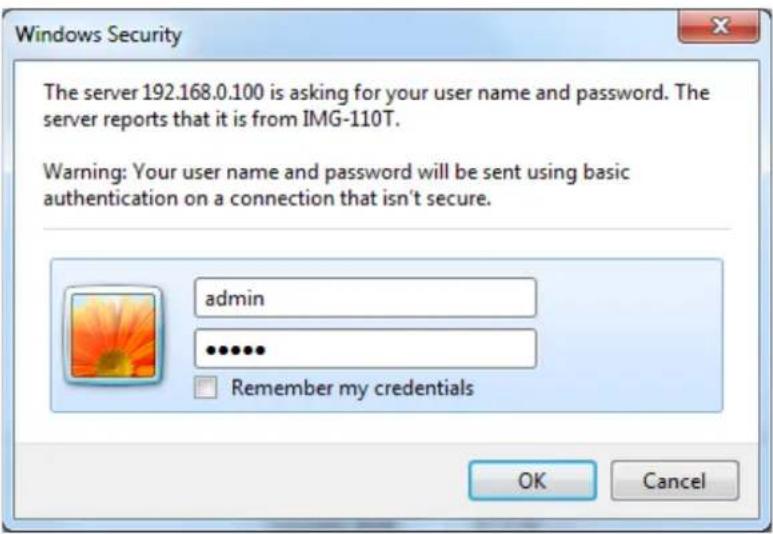
Figure 3-4: Web Login Screen
- After entering the username and password, the main screen appears as Figure 3-5 shows.

Figure 3-5: Web Main Screen of Industrial Modbus Gateway

For security reason, please change and memorize the new password after this first setup.
- Only accept command in lowercase letter under web interface.
3.3.3 Remote IP-based Telnet Interface
The Industrial Modbus Gateway offers management features that allow users to manage the Industrial Modbus Gateway from anywhere on the network through remote IP-based telnet interface. After you set up your IP address for the Industrial Modbus Gateway, you can access the Industrial Modbus Gateway's telnet interface applications directly in your PC by entering the IP address of the Industrial Modbus Gateway under command prompt.
![graph LR A["Modbus Gateway"] -->|RJ45/UTP Cable| B["PC/Workstation with Telnet Client 192.168.0.x"]](/content/2026/05/1081726/images/e7e0475751c9ef0c6de04644122706f733a9c61add3281d7fd9d41c8045854dc.jpg)
Figure 3-6: Telnet Management Diagram
3.3.4 Login the Industrial Modbus Gateway Telnet Interface
The following shows how to start up the Telnet Management of the Industrial Modbus Gateway. Note the Industrial Modbus Gateway is configured through an Ethernet connection. Please make sure the manager PC must be set to the same IP subnet address.
For example, the default IP address of the Industrial Modbus Gateway is 192.168.0.100, then the manager PC should be set to 192.168.0.x (where x is a number between 1 and 254, except 100) and the default subnet mask is 255.255.255.0.
Logging in to the Industrail Modbus Gateway
- Access Command Prompt and enter telnet 192.168.0.100 to access the Telnet interface.
- When the following dialog box appears, please enter the default user name and password "admin". The login screen in Figure 3-7 appears.
Default Username: admin
Default Password: admin

Figure 3-7: Telnet Login Screen
- After entering the username and password, the telnet main screen appears as Figure 3-8 shows.

Figure 3-8: Telnet Main Screen of Industrial Modbus Gateway

For security reason, please change and memorize the new password after this first setup.
- Only accept command in lowercase letter under web interface.
3.4 PLANET Smart Discovery Utility
For easily listing the Industrial Modbus Gateway in your Ethernet environment, the Planet Smart Discovery Utility is an ideal solution. The following installation instructions are to guide you to running the Planet Smart Discovery Utility.
- Insert the attached user's manual CD in the CD-ROM Drive.
- Find and deposit the Planet Smart Discovery Utility in administrator PC.
- Run this utility as the following screen appears.
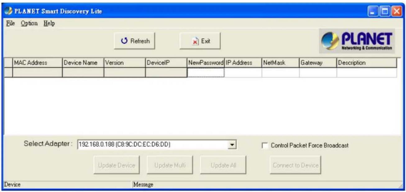
Figure 3-9: Planet Smart Discovery Utility Screen

If there are two LAN cards or above in the same administrator PC, choose a different LAN card by using the "Select Adapter" tool.
- Press the "Refresh" button for the currently connected devices in the discovery list as the screen shows below:

Figure 3-10: Planet Smart Discovery Utility Screen
- This utility shows all necessary information from the devices, such as MAC address, device name, firmware version and device IP subnet address. It can also assign a new password, IP subnet address and description for the devices.
- After the setup is completed, press the "Update Device", "Update Multi" or "Update All" button to take effect. The functions of the 3 buttons above are shown below:
■ Update Device: Use the current setting on one single device.
■ Update Multi: Use the current setting on multi-devices.
■ Update All: Use the current setting on all the devices in the list.
The same functions mentioned above also can be found in the "Option" tool bar.
- By clicking the "Control Packet Force Broadcast" function, it allows you to assign a new setting value to the Web Smart Switch under a different IP subnet address.
- Press the "Connect to Device" button and input the username and password in the web login screen, and the web main screen appears in Figure 3-5.
- Press the "Exit" button to shut down the Planet Smart Discovery Utility.
3.5 PLANET Modbus Gateway Utility
For easily listing and manage the Industrial Modbus Gateway in your Ethernet environment, the Planet Modbus Gateway Utility is an ideal solution. The following installation instructions are to guide you to installing and running the Planet Modbus Gateway Utility.
3.5.1 Installing PLANET Modbus Gateway Utility
The following install instructions guide you to the installations of the Planet Modbus Gateway Utility.
- Insert the attached user's manual CD in the CD-ROM Drive.
- Find the PLANET Modbus Gateway Utility_v1.0.exe from the CD-ROM as the icon is shown below:
PLANET Modbus Gateway Utility_v1.0.exe
- Press the PLANET Modbus Gateway Utility_v1.0.exe and follow the on-screen instructions to install the utility. The install procedures in the following screens appear.
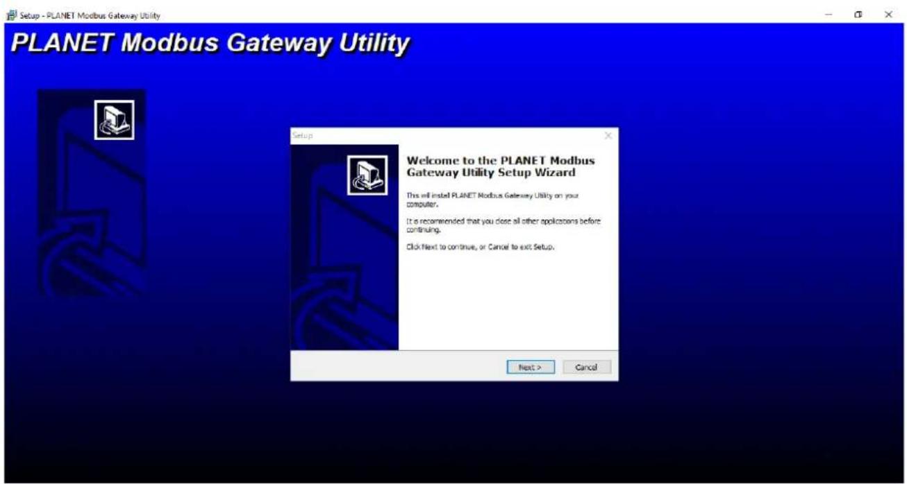
Figure 3-11: Planet Modbus Gateway Utility Install Process Screen

Figure 3-12: Planet Modbus Gateway Utility Install Process Screen

Figure 3-13: Planet Modbus Gateway Utility Install Process Screen

Figure 3-14: Planet Modbus Gateway Utility Install Process Screen
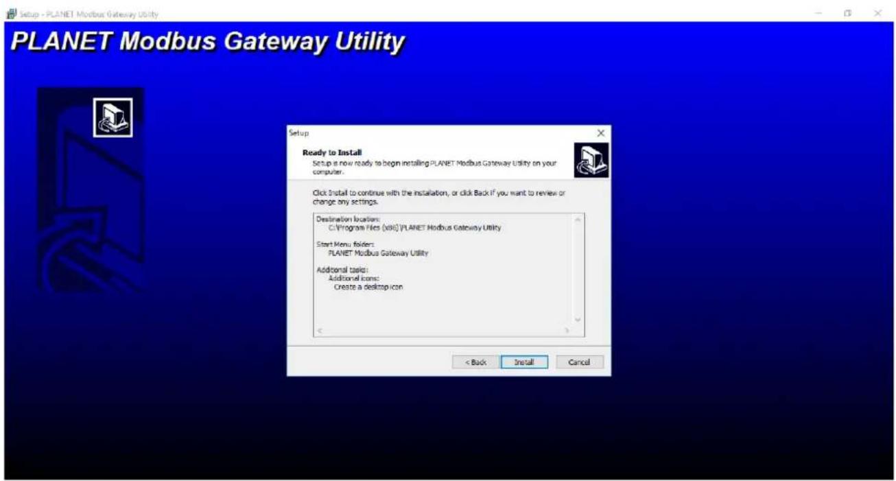
Figure 3-15: Planet Modbus Gateway Utility Install Process Screen
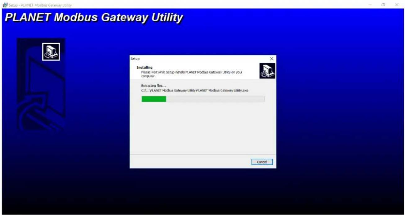
Figure 3-16: Planet Modbus Gateway Utility Install Process Screen

Figure 3-17: Planet Modbus Gateway Utility Install Complete Screen
- Find the PLANET Modbus Gateway UtilityV1.0 icon on the desktop of administrator PC and double-click it as the icon is shown below:

- After the installation is completed, execute the utility. The screen in Figure 3-18 appears.

Figure 3-18: Planet Modbus Gateway Utility Main Screen
3.5.2 PLANET Modbus Gateway Utility Menu Bar
The Planet Modbus Gateway Utility menu bar has the following options:
- System(S)
- Tools(Y)

Figure 3-19: Planet Modbus Gateway Utility Tool Bar Screen
3.5.2.1 System(S)
This function provides Select network adapter and Quit for closing the PLANET Modbus Gateway Utility.

Figure 3-20: Planet Modbus Gateway Utility Tool Bar System Screen
Select network adapter
This option allows you to select the network adapter for management; press "OK" to apply the setting.
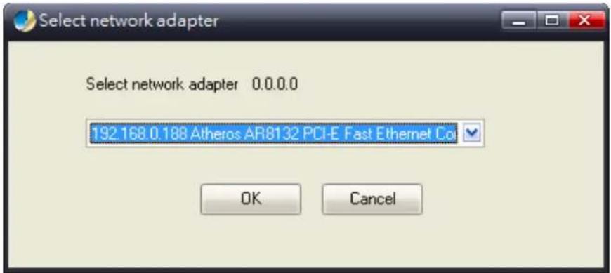
Figure 3-21: Planet Modbus Gateway Utility Tool Bar System -- Select network adapter Screen
Quit
This option allows you to press "Quit" for closing the PLANET Modbus Gateway Utility.

Figure 3-22: Planet Modbus Gateway Utility Tool Bar System -- Quit Screen
3.5.2.2 Tools(Y)
This function provides the following options:
- Search Device
- Set Search Type
- Set Timing Save
- Manual Add Device
- Batch IP Settings (B)

Figure 3-23: Planet Modbus Gateway Utility Tool Bar -- Tools Screen
Search Device
This option allows you to search the connected Industrial Modbus Gateway for further management.

Figure 3-24: Planet Modbus Gateway Utility Bar Tool -- Search Device Screen
Set Search Type
This option allows you to specify which equipment is used for further management; the available options are shown below:
- Serial Server
- Switch
- All

Figure 3-25: Planet Modbus Gateway Utility Tool Bar -- Set Search Type Screen

The Switch option is a future feature which is not applicable at the moment.
- Suggest choose the option of Serial Server or All for this function.
Set Timing Save
This option allows you to save timing device alert information to the database or specified file. Enable "True" for setting the timing save function. In the "Activation time", set the cycle time of the save alarm information to "0H 30M 0S", meaning it is saved every 30 minutes. In "Type", select "Saved to the database" or "Saved to the TXT file". When selecting "Saved to the database", it is saved in "alert log query". When selecting "Saved to a text file", a file name has to be given and then it is saved in whatever folder you want.

Figure 3-26: Planet Modbus Gateway Utility Tool Bar -- Set Timing Save Screen
Manual Add Device
This option allows you to manually set up IP search device and send search unicast packets; there are two ways to manually add the device as shown below:
1: Add "On line Devices" under an existing IP address, click "\" in front of the desired IP address and click on ">" to add IP address;
2: A "Device IP Address" is filled out to manually enter the IP address and click "Add" to add the IP address.
Click OK for adding a unicast packet to search equipment. If the router's port mapping is configured, it can implement search across route. Discovery process begins from PC Port 65533, Port 65534 sends commands to the specified device, and then Port 65533 responds to a search and send confirmation to PC Port 65534 to complete the search.

Figure 3-27: Planet Modbus Gateway Utility Tool Bar -- Manual Add Device Screen
Batch IP Settings
This option allows you to set up IP addresses for a group of devices so as to avoid one-by-one setting, which can save a lot of time.
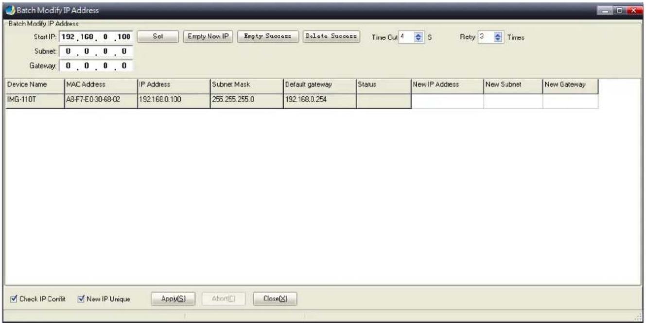
Figure 3-28: Planet Modbus Gateway Utility Tool Bar -- Batch IP Settings Screen

The IP address range is 1-254.
3.5.3 PLANET Modbus Gateway Utility Shortcut Menu Bar
The Planet Modbus Gateway Utility shortcut menu bar has the following options:
- User Manager
- Import Network Topology
-Export Network Topology
-Zoom In
-Zoom Out
-Search Device
-Save Topology
-Delete Topology
-Batch IP Settings
-Batch Monitoring IP Settings
-Hide Device Tree
-Hide Alarm List
-Auto Refresh Topology
-Refresh Interval

Figure 3-29: Planet Modbus Gateway Utility Shortcut Menu Bar Screen
3.5.3.1 User Manager

This function provides setting up user name and password for PLANET Modbus Gateway Utility to avoid illegal lification on the Industrial Modbus Gateway.
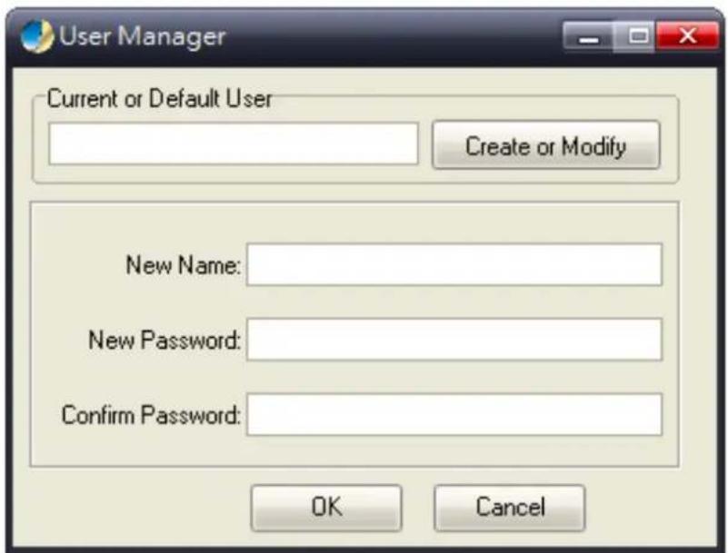
Figure 3-30: Planet Modbus Gateway Utility Shortcut Menu Bar -- User Manager Screen
The page includes the following fields:
| Object | Description |
| • New Name | The ID of the user.Maximum length: 18 characters. |
| • Password | Enter the user's new password here.Maximum length: 18 characters. |
| • Confirm Password | Please enter the user's new password here again to confirm. |
Button
OK
Click to apply changes.

Please remember the newly set-up "user name" and "password"; in case the user name and password are forgotten, please re-install the PLANET Modbus Gateway Utility.
3.5.3.2 Import Network Topology

: This function provides the import topology in PLANET Modbus Gateway Utility.
Step 1: Click the shortcut icon for the "import Network Topology" and enter search screen of administrator PC.
Step 2: Choose a ".BEF" document to be imported.
3.5.3.3 Export Network Topology

This function provides the export topology in PLANET Modbus Gateway Utility and saved as “.BEF” document. For her review, please use the “Import Network Topology” function.
Step 1: Click the shortcut icon for the "Export Network Topology" and enter screen of administrator PC.
Step 2: Choose the saving route and fill in the document name, and click Save to save as “.BEF” document.
3.5.3.4 Zoom In

: This function provides the zoom in topology in PLANET Modbus Gateway Utility.
3.5.3.5 Zoom Out

: This function provides the zoom out topology in PLANET Modbus Gateway Utility.
3.5.3.6 Search Device

: This option allows you to search the connected Industrial Modbus Gateway for further management .

Figure 3-31: Planet Modbus Gateway Utility Shortcut Menu Bar -- Search Device Screen
3.5.3.7 Save Topology

: This option allows you to change the topology and save it in Industrial Modbus Gateway Utility.
3.5.3.8 Delete Topology

: This option allow to delete the change of topology and save it in Industrial Modbus Gateway Utility.
3.5.3.9 Batch IP Settings

: This options allows you to set up IP addresses for a group of devices so as to avoid one-by-one setting, which can save of time.

Figure 3-32: Planet Modbus Gateway Utility Shortcut Menu Bar -- Batch IP Settings Screen

The IP address range is 1-254.
3.5.3.10 Batch Monitoring IP Settings

: This option allows you to set up Batch Monitoring IP addresses for a group of devices.

Figure 3-33: Planet Modbus Gateway Utility Shortcut Menu Bar -- Batch Monitoring IP Settings Screen
Button

Click to apply changes.
3.5.3.11 Hide Device Tree/ Show Device Tree

This option allows you to hide or show the device tree in Industrial Modbus Gateway Utility.
3.5.3.12 Hide Alarm List/ Show Alarm List

This option allows you to hide or show the alarm list in Industrial Modbus Gateway Utility.
3.5.3.13 Auto Refresh Topology

This option allows you to enable or disable Auto Refresh Topology in Industrial Modbus Gateway
Utility.
3.5.3.14 Refresh Interval

This option allows you to assign time for Refresh Interval in Industrial Modbus Gateway
Utility; the available options are 10 S, 30 S, 1M, 10M, 30M and 60M.
3.5.4 PLANET Modbus Gateway Utility Device Function
The Planet Modbus Gateway Utility provides the following options for Industrial Modbus Gateway device management.
- Web Console
- Device Name
-Network Settings
-Reset Factory Settings
-Recent Alarm
3.5.4.1 Web Console
This function provides Web interface access to PLANET Modbus Gateway.

Figure 3-34: Planet Modbus Gateway Utility Device Function -- Web Console Screen
3.5.4.2 Device Name
This function is to change the Device name and Device number of PLANET Modbus Gateway.

Figure 3-35: Planet Modbus Gateway Utility Device Function -- Device Name Screen
Button

Click to apply changes.
3.5.4.3 Network Settings
This function is to change the IP subnet address of PLANET Modbus Gateway.

Figure 3-36: Planet Modbus Gateway Utility Device Function -- Network Settings Screen
Button

Click to apply changes.
3.5.4.4 Reset Factory Settings
This function is to reset PLANET Modbus Gateway to default as the procedure is shown below:
Step 1: Activate PLANET Modbus Gateway Utility.
Step 2: Search the Industrial Modbus Gateway that needs to be reset to default and choose the device.
Step 3: Right-click to choose the "Restore Factory Settings".

Figure 3-37: Planet Modbus Gateway Utility Device Function -- Restore Factory Settings Screen
Step 4: Click "Yes" when the "Are you sure to restore factory settings" pop window appears.
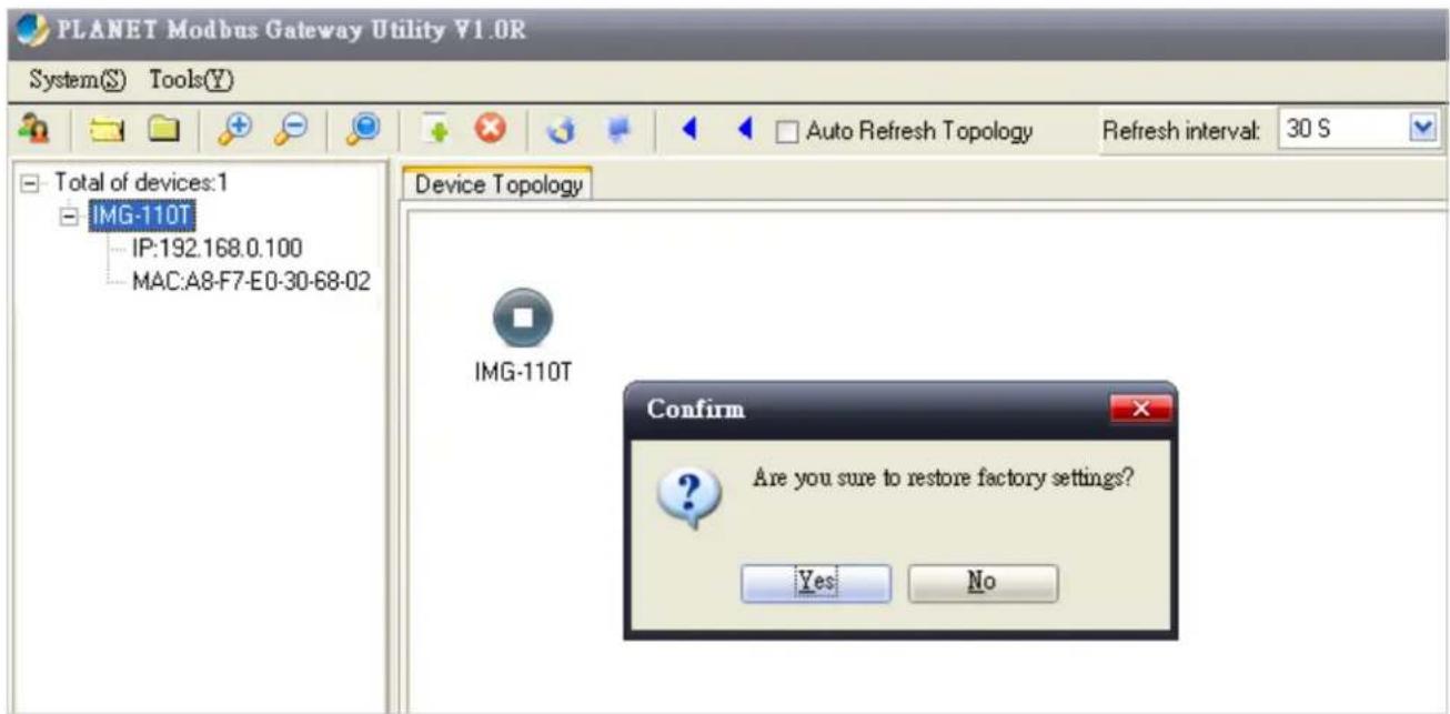
Figure 3-38: Planet Modbus Gateway Utility Device Function -- Restore Factory Settings Screen
Step 5: Press "OK" to complete the factory default procedure.

Figure 3-39: Planet Modbus Gateway Utility Device Function -- Restore Factory Settings Screen
Button

: Click to apply changes.
Step 6: Search the device again and you will see the Industrial Modbus Gateway with default IP address, and username and password: "admin".

Figure 3-40: Planet Modbus Gateway Utility Device Function -- Restore Factory Settings Screen
3.5.4.5 Recent Alarm
This function is to display the alarm information of PLANET Modbus Gateway and also save the alarm messages for further review or export the alarm message as an excel file. The three options for the alarm message are shown below:
-Clear-clear alarm messages.
-Save-save alarm messages.
-Query-alarm log export.
| Recent Alarm | |||||
| MessageType | Device | Description | Time Issued | ||
| IP Address | 192.168.0.100 | MAC Address A8-F7-E0-30-68-02 | Description | ||
Figure 3-41: Planet Modbus Gateway Utility Device Function -- Recent Alarm Screen
4. WEB MANAGEMENT
The Industrial Modbus Gateway provides Web interface for management function configuration which makes the Industrial Modbus Gateway operate more effectively. It can be configured through the various web browser tools. A network administrator can manage and monitor the Industrial Modbus Gateway from the local LAN. This section indicates how to configure the Industrial Modbus Gateway to enable its management to function.
4.1 Web Main Page
After a successful login and the web main screen appears, the web main screen displays the overview information of Industrial Modbus Gateway. The web main screen in Figure 4-1 appears.

Figure 4-1: Web Main Screen
As listed on the left side of the web main screen, the configurable management functions are shown below:
| ■ Overview | Display the basic settings information and network information of Industrial Modbus Gateway. |
| ■ Network Settings- | Set up the IP address of the Industrial Modbus Gateway. |
| ■ Serial Settings | COM Settings:configure serial port parameters as shown below:Basic Settings (Alias/ Baud Rate/ Data Bits/ Stop Bits/Parity Bits/ Flow Control).Advance Settings (RTS control/DTR control).COM Information:display serial port settings related information. |
| ■ Modbus Settings | Modbus Parameters:configure Modbus parameters as shown below:Basic Settings (Modbus Settings, Response Timeout & Interval Timeout)Slave ID:configure Slave ID Map Table parameters. |
| ■ State Monitoring | Display the serial port communication traffic counters in transmit and receive. |
| ■ Access Control | Configure access control parameters as shown below:Device Security: allow disable or enable Web Console, Telnet Console, Device Search, Firmware Upgrade function.IP Filtering: set up the IP address filtering function.MAC Filtering: set up the MAC address filtering function.User Management: allow to modify the username and password or disable authentication function. 3 sets of username and password can be configured. |
| ■ System Management | Configure system management parameters as shown below:System Information: display the system information of Industrial Modbus Gateway.System File: provide factory default configuration; download and upload Configuration file from Local PC and Upgrade Firmware from Local PCision & Reboot: provide system logout and system reboot . |
4.2 Overview
The System Information page provides information for the current device. It helps a network manager to identify the versions and IP Address. The screen in Figure 4-2 appears.
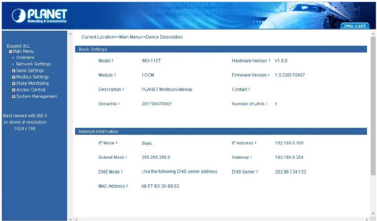
Figure 4-2: Overview Screen
The page includes the following fields:
| Basic Settings | |
| • Model | The model name of Industrial Modbus Gateway. |
| • Hardware Version | The current hardware version of Industrial Modbus Gateway. |
| • Module | The module information of Industrial Modbus Gateway. |
| • Firmware Version | The current firmware version of Industrial Modbus Gateway. |
| • Description | The description of Industrial Modbus Gateway. |
| • Contact | The contact information of Industrial Modbus Gateway. |
| • Serial No. | The serial number information of Industrial Modbus Gateway. |
| • Number of LANs | The number of LANs information of Industrial Modbus Gateway. |
| Network Information | |
| • IP Mode | The current IP operation mode of Industrial Modbus Gateway. |
| • IP Address | The current IP Address of the Industrial Modbus Gateway. The IP Address could be manually assigned. The factory default value is 192.168.0.100. |
| • Subnet Mask | The current IP Subnet Mask setting on the Industrial Modbus Gateway. The factory default value is 255.255.255.0. |
| • Gateway | The default gateway for the Industrial Modbus Gateway; the factory default value is 192.168.0.254. |
| • DNS Mode | The DNS mode information of Industrial Modbus Gateway. |
| • DNS Server | The DNS server information of Industrial Modbus Gateway. |
| • MAC Address | The MAC address information of Industrial Modbus Gateway. |
4.3 Network Settings
This function allows setting the value for network configuration. The value is DHCP client, IP address, Subnet Mask, or Gateway, DNS. Press the "Submit" button to set the value and the screen in Figure 4-3 appears.
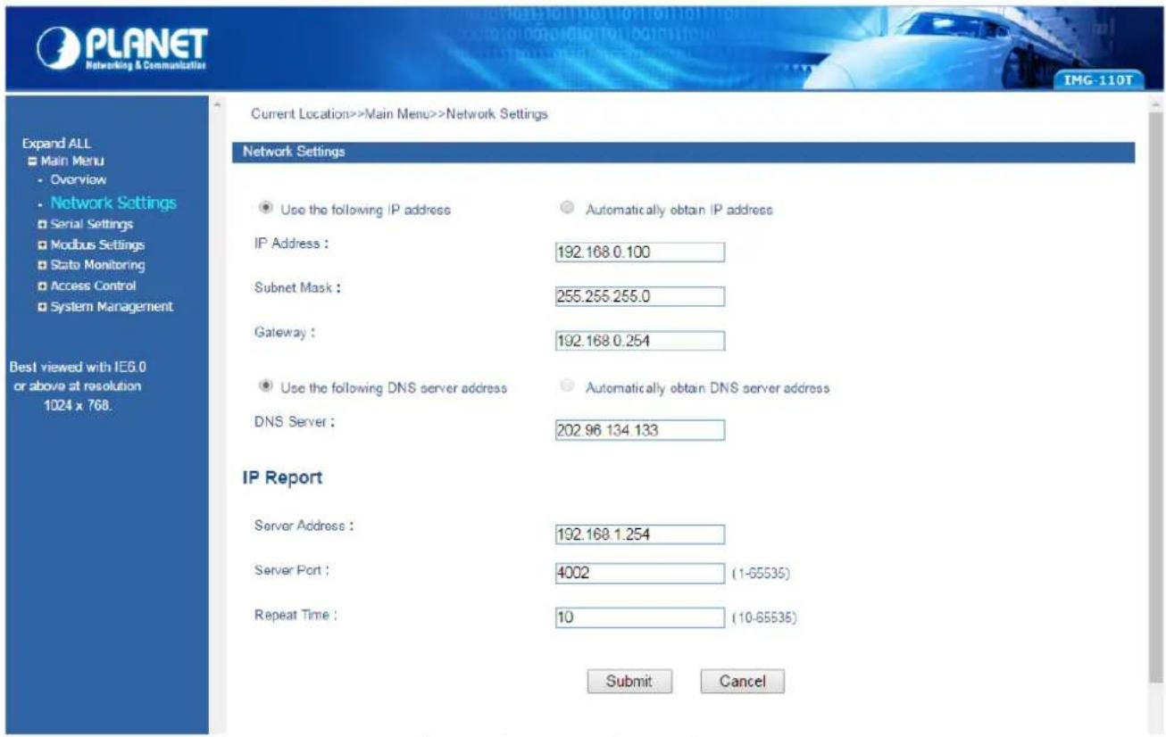
Figure 4-3: Network Settings Screen
The page includes the following configurable data:
| Network Settings | |
| • Use the following IP Address | Choose static IP address for the Industrial Modbus Gateway. |
| • Automatically Obtain IP Address | Enable the DHCP function for the Industrial Modbus Gateway.When enabling this function, the Industrial Modbus Gateway will send a DHCP request to the DHCP server in the network. Once the DHCP Server gets the request, it will assign a dynamic IP address, subnet mask and gateway to the Industrial Modbus Gateway. The factory default setting is “Disable”. |
| • IP Address | Manually assign IP address to the Industrial Modbus Gateway.The factory default value is 192.168.0.100 |
| • Subnet Mask | Manually assign subnet mask to the Industrial Modbus Gateway.The factory default value is 255.255.255.0 |
| • Gateway | Manually assign Gateway to the Industrial Modbus Gateway.The factory default value is 192.168.0.254 |
| • Use the following DNS Server Address | Choose static IP address for the DNS server of Industrial Modbus Gateway. |
| • Automatically obtain DNS server address | Enable the DHCP function for the DNS server of Industrial Modbus Gateway. |
| • DNS Server | DNS is the way that Internet domain names are identified and translated into IP addresses. A domain name is an alphanumeric name, such as planet.com, which is usually easier to remember. Assign the DNS server IP address. |
| IP Report | |
| • Server Address | Need to report to the top of the host IP. |
| • Server Port | When reporting or listening to the port, the default is 4002. |
| • Repeat Time | Report IP interval (seconds); the default is 10. |
Button
Submit
Click to apply changes.
4.4 Serial Settings
This function provides serial port COM settings and displays the serial port COM information.
4.4.1 COM Settings
This function allows setting the value for serial port COM configuration. Press the "Submit" button to set the value and the screen in Figure 4-4 appears.

Figure 4-4: Serial Settings -- COM Settings Screen
The page includes the following configurable data:
| Port Setting | |
| • Port | Display the COM1 information. |
| Settings | |
| • Alias | Manually input the description of serial port; the available range is 30 characters. |
| • Baud Rate | It is a parameter to check the communication speed. It shows to transfer how many bits in 1 second. The available options are shown below:300/600/1200/2400/4800/9600/19200/38400/57600/115200. |
| • Data Bits | It is a parameter to check the actual data bits in communication; when PC sends a Packet, actual data is not 8 bits; the standards are 7 bits and 8 bits. |
| • Stop Bits | The last bit of the single packet -- the typical values are 1 bits and 2 bits. |
| Parity Bits | It is a simple method to check out fault in serial communication; it has 4 types: Even/Odd/Mark/Space. |
| Flow Control | Flow control is determined by product hardware. For some reason, it cannot communicate. When communication is blocked, open the flow control to ease. Flow control allows the data receiving device to notify the data sending device when it is unable to receive the data, so that it can be stopped. It includes XON/XOFF,DTR/DSR, and RTS/CTS. |
| Work Mode | Work mode is determined by product hardware. When the product is RS485 serial port, it will display RS-485. When the product is the RS232 interface, it will display RS-232. |
| Advance Settings | According to the needs, the user can modify the output state of the DTR and RTS signals at any time |
| RTS Ctrl | [Force ON]RTS signal is automatically set to the ON state after every time you open the serial port, and it is forbidden to change the user to modify. (When the RTS flow control mode is turned on, it is invalid.)[Force OFF]RTS signal is automatically set to the OFF state after every time you open the serial port, and it is forbidden to change the user to modify. (When the RTS flow control mode is turned on, it is invalid.) |
| DTR Ctrl | [Force ON]DTR signal is automatically set to the ON state after every time you open the serial port, and it is forbidden to change the user to modify. (When the DTR flow control mode is turned on, it is invalid.)[Force OFF]DTR signal is automatically set to the OFF state after every time you open the serial port, and it is forbidden to change the user to modify. (When the DTR flow control mode is turned on, it is invalid.) |
| Apply to All Ports | Choose this option to apply the setting to all ports. |
Button
Submit
Click to apply changes.
4.4.2 COM Information
The function displays the serial port COM information like the current communication parameters of serial port as shown below:
-Port
-Alias
-Baud Rate
-Data Bits
-Stop Bits
-Parity Bits
-Flow Control
-FIFO
-Work Mode
The screen in Figure 4-5 appears.

Figure 4-5: Serial Settings -- COM Information Screen
4.5 Modbus Settings
This function provides Modbus parameters settings and slave ID settings.
4.5.1 Modbus Parameters
This function allows setting the value for serial port COM configuration. Press the "Submit" button to set the value and the screen in Figure 4-4 appears.

Figure 4-6: Modbus Parameters Screen
The page includes the following fields:
| Modbus Setting | |
| Initial Delay | This function due to the Modbus from the machine device initialization time is relatively long. In order to avoid before these devices are not initialized, the request is sent to the frame access, so the Industrial Modbus Gateway sets the initialization delay time to decide the time delay of the first request that can be sent. |
| Modbus TCP Exception | This parameter is used to display the Modbus TCP exception in the Modbus monitoring software. Once the parameter is enabled, the Industrial Modbus Gateway sends a Modbus TCP exception to the Modbus monitoring software. |
| Response Timeout & Interval Timeout | |
| • Port | Indicates the TCP/ProCOM and Port1. |
| • Response Timeout (10-120000ms) | The Modbus is a master and slave protocol; the master station equipment accesses the slave station equipment which needs a response timeout; the time is the gateway device response time.This parameter is found in the second and third steps in the diagram below. The gateway equipment forwards the request information of the master station to the slave station, and if there is no reply message from the slave station equipment in the response time, the gateway equipment sends out the timeout response information to the master station. The available range is 10-120000ms. |
| • Inter-character Timeout(0ms,10-500ms) | In a single frame, the time difference is between a single character and the next character. When the value is 0, the default is 3.5T time, which is equal to 3.5 characters.The available range is 10-500ms. |
| • Inter-frame Delay(0ms,10-500ms) | The current RTU response with the next RTU request is between the time intervals. The default is 0ms. This feature is to avoid the RTU request from the station equipment. Set the time interval to facilitate the RTU from the station equipment that has adequate time to handle the request. The available range is 10-500ms. |
 | |
Button
Submit
Click to apply changes.
4.5.2 Slave ID
The Modbus protocol provides a unique ID number (1 \~ 247) to all of the slave devices. The ID number is used to identify the address of the slave device to respond to requests from the master device. The Modbus equipment ID number is set by the manufacturers. Most of them can be modified. It is an actual ID number.
Virtual ID is used to specify the ID Modbus of each connected gateway. When the Modbus master device accesses the virtual ID, the gateway device converts the virtual ID address into the actual ID address. When the Modbus slave device responds to the master device, the gateway device will convert the actual ID address to the virtual ID address. For the Modbus master, it only needs to access the "virtual" ID. The conversion between the virtual ID and the actual ID is called ID mapping. The Gateway device achieves the function of ID mapping by setting the ID range and ID offset. Only the channel type in the slave mode of the channel can be set up, including the Slave ASCII, Slave RTU and Slave TCP. Virtual ID + ID Offset = Real ID (Actual ID).
![graph LR A["Master"] -->|Request| B(MODBUS Gateway) B -->|Response| A B -->|Request| C["Slave"] C -->|Response| B style B fill:#888,stroke:#333 note1["① Request"] --> B note2["② Request"] --> C note3["③ Response"] --> C note4["④ Response"] --> B](/content/2026/05/1081726/images/47fb4cf5fcf4c5c27b557df0f86dcde42e17d9a49200ea0b709272bc008337ab.jpg)
This function allows setting the value for slave ID configuration. Press the "Add" and "Submit" buttons to set the value and the screen in Figure 4-7 appears.
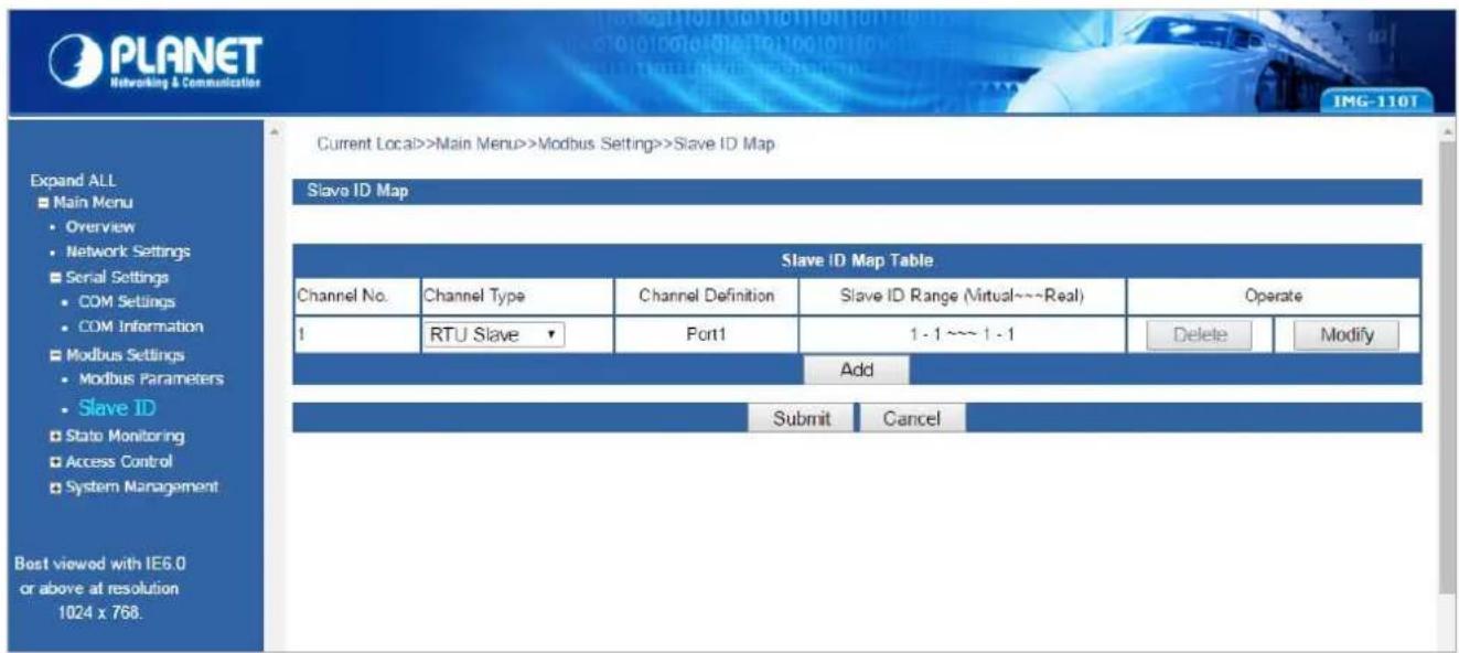
Figure 4-7: Slave ID Screen
The page includes the following fields:
| Slave ID Map Table | |
| Channel No. | Display the channel number. |
| Channel Type | This parameter is to choose RTU Master/RTU Slave/ASCII Master/ASCII Slave operation modes; the default mode is RTU Slave. |
| Channel Definition | Display the channel definition information. |
| Slave ID Range (Virtual~~Real) | Display the Slave ID Range information. |
| Operate | Provide Delete and Modify button. |
Press Add to access the following parameters screen.

Figure 4-8: Slave ID Parameters Screen
The page includes the following fields:
| Remote IP Address | Allow input the remote IP address. |
| TCP Port | This parameter is to input the TCP port and available range is 1-65535. |
| Slave ID Start | This parameter is to input the start Slave ID and available range is 0-247. |
| Slave ID End | This parameter is to input the end Slave ID and available range is 0-247. |
| Slave ID Offset | This parameter is to input the offset Slave ID and available range is -253-253. |
Buttons
Submit
Click to apply changes.
Affirm
Click to apply changes.
Delete
Click to delete setting.
Modify
: Click to modify setting.
RTU Master Mode
This function allows the users to use Modbus RTU master device and Modbus TCP device to achieve communication. The operation mode of the Industrial Modbus Gateway is set to RTU Master.
Step 1: Choose "RTU Master" in Channel Type.
Step 2: Press the "Add" button to input the setting parameters.
Step 3: After setup is completed, press the "Affirm" button to take effect.
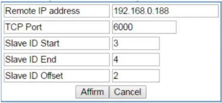
Figure 4-9: Slave ID Parameters Screen

Figure 4-10: Slave ID-RTU Master Screen
The IP address of the TCP is 192.168.0.188 (For example, the IP address of the local PC), the TCP port number is 6000, and the virtual ID is 3\~4. Offset is 2.
RTU Slave Mode
This function allows the users to use Modbus TCP master device and Modbus RTU device to achieve communication. The operation mode of the Industrial Modbus Gateway is set to RTU Slave.
Step 1: Choose" RTU Slave" in Channel Type.
Step 2: Press the "Modify" button to input the setting parameters.
Step 3: After setup is completed, press the "Affirm" button to take effect.
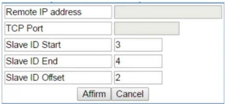
Figure 4-11: Slave ID Parameters Screen

Figure 4-12: Slave ID-RTU Slave Screen
The virtual ID is 3\~4. Offset is 2 in Channel No 1.
ASCII Master Mode
This function allows the users to use Modbus ASCII master device and Modbus TCP device to achieve communication. The operation mode of the Industrial Modbus Gateway is set to ASCII Master.
Step 1: Choose "ASCII Master" in Channel Type.
Step 2: Press the "Add" button to input the setting parameters.
Step 3: After setup is completed, press the "Affirm" button to take effect.

Figure 4-13: Slave ID Parameters Screen
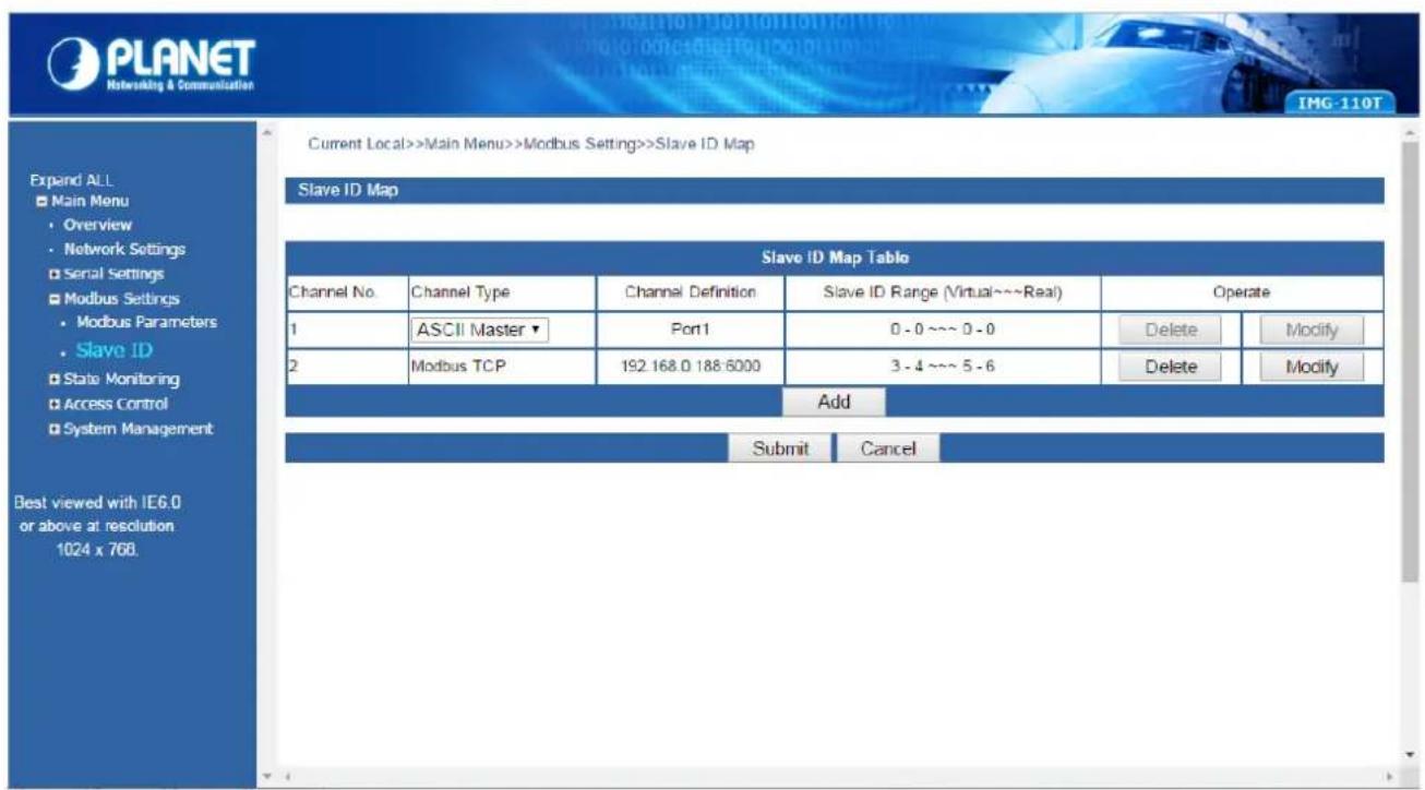
Figure 4-14: Slave ID-ASCII Master Screen
The IP address of the TCP is 192.168.0.188 (For example, the IP address of the local PC), the TCP port number is 6000, and the virtual ID is 3\~4. Offset is 2.
ASCII Slave Mode
This function allows the users to use Modbus TCP master device and Modbus ASCII device to achieve communication. The operation mode of the gateway is set to ASCII Slave.
Step 1: Choose "ASCII Slave" in Channel Type.
Step 2: Press the "Modify" button to input the setting parameters.
Step 3: After setup is completed, press the "Affirm" button to take effect.

Figure 4-15: Slave ID Parameters Screen

Figure 4-16: Slave ID-ASCII Slave Screen
The virtual ID is 3\~4. Offset is 2 in Channel No 1.
4.6 State Monitoring
This function provides Industrial Modbus Gateway serial COM port traffic counter in Transmit (TX) and Receive (RX).
4.6.1 COM State
The function displays the serial port COM state information like the current traffic counter of serial port as the screen in Figure 4-17 appears.

Figure 4-17: State Monitoring -- COM State Screen
The page includes the following fields:
| Port | Indicate the port number. |
| TX | Display the serial COM port traffic counter in Transmit (TX). |
| RX | Display the serial COM port traffic counter in Receive(RX). |
| TX Total | Display the serial COM port total bytes traffic counter in Transmit (TX). |
| Rx Total | Display the serial COM port total bytes traffic counter in Receive(RX). |
| CTS | Indicate the “On” or “Off” status of CTS function. |
| DSR | Indicate the “On” or “Off” status of DSR function. |
| RI | Indicate the “On” or “Off” status of RI function. |
| DCD | Indicate the “On” or “Off” status of DCD function. |
| DTR | Indicate the “On” or “Off” status of DTR function. |
| RTS | Indicate the “On” or “Off” status of RTS function. |
| Clear ALL | This function allows to clear the current serial COM port traffic counter in Transmit (TX) and Receive (RX). |
4.7 Access Control
This function provides access control parameters of Industrial Modbus Gateway, including:
-Device Security
-IP Filtering
-MAC Filtering
-User Management
4.7.1 Device Security
This function allows setting up the device security functions of Industrial Modbus Gateway. Press the "Submit" button to apply the setting as the screen in Figure 4-18 appears.
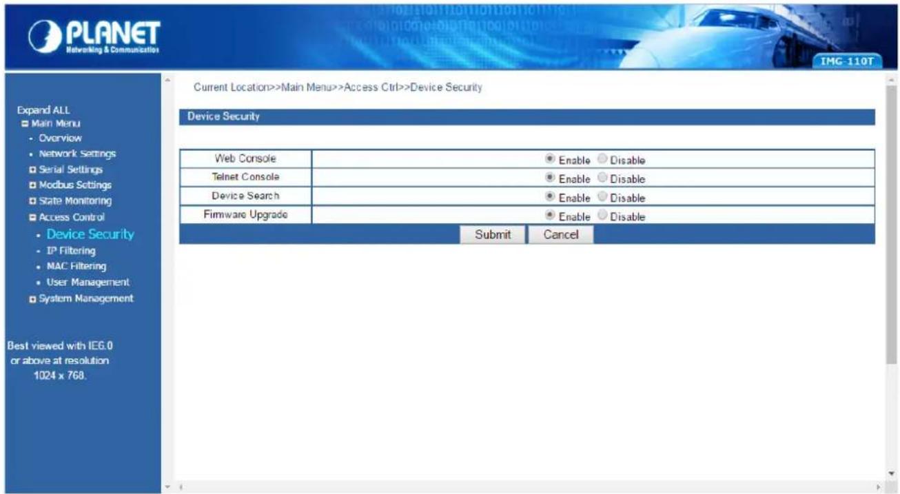
Figure 4-18: Access Control -- Device Security Screen
The page includes the following configurable data:
| Web Console | This function provides “Disable” or “Enable” the Web management interface. |
| Telnet Console | This function provides “Disable” or “Enable” the Telnet management interface. |
| Device Search | This function provides “Disable” or “Enable” the device search function. |
| Firmware Upgrade | This function provides “Disable” or “Enable” the firmware upgrade function. |
Button
Submit
Click to apply changes.
4.7.2 IP Filtering
This function allows setting up the IP Filtering function of Industrial Modbus Gateway. Press the "Submit" button to apply the setting as the screen in Figure 4-19 appears.

Figure 4-19: Access Control -- IP Filtering Screen
The page includes the following configurable data:
| IP Filtering | This function provides “Disable” or “Enable” the IP Filtering function. |
| Filtering Rule | This function provides “Allowed” or “Forbidden” options for the filtering rule. |
| Number | Indicate the number from 1 to 16 for filtering rules. |
| State | This function provides “Disable” or “Enable” for per filtering rule. |
| Access Permission | This function provides “Allowed” or “Forbidden” for per filtering rule. |
| IP Address | This function allows inputting the IP address. |
| Subnet Mask | This function allows inputting the Subnet Mask value. |
Button
Submit
Click to apply changes.
4.7.3 MAC Filtering
This function allows setting up the MAC Filtering function of Industrial Modbus Gateway. Press the "Submit" button to apply the setting as the screen in Figure 4-20 appears.
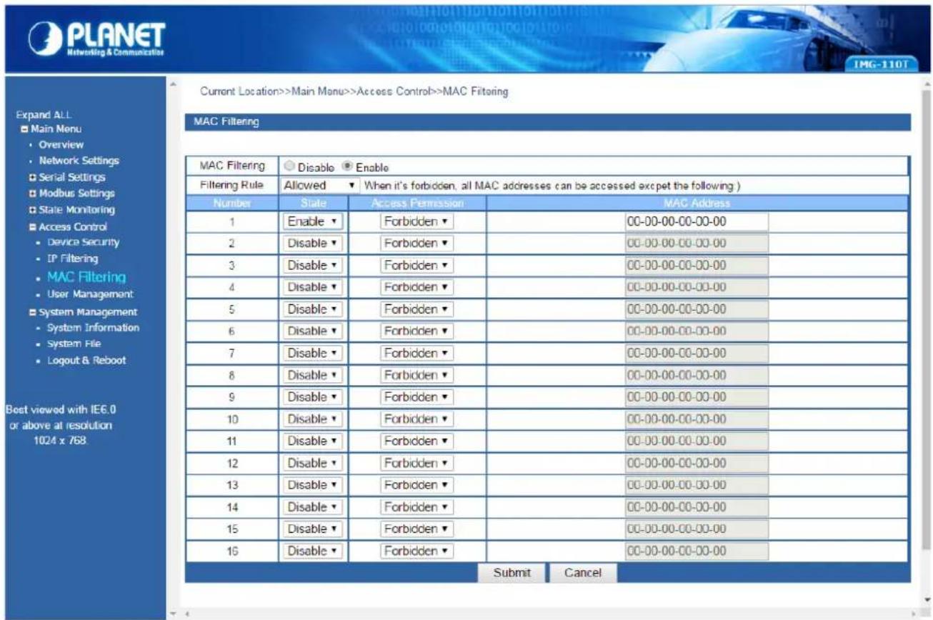
Figure 4-20: Access Control -- MAC Filtering Screen
The page includes the following configurable data:
| MAC Filtering | This function provides “Disable” or “Enable” the MAC Filtering function. |
| Filtering Rule | This function provides “Allowed” or “Forbidden” options for the filtering rule. |
| Number | Indicate the number from 1 to 16 for filtering rules. |
| State | This function provides “Disable” or “Enable” for per filtering rule. |
| Access Permission | This function provides “Allowed” or “Forbidden” for per filtering rule. |
| MAC Address | This function allows inputting the MAC address; the format must be xx-xx-xx-xx-xx-xx. |
Button
Submit
Click to apply changes.
4.7.4 User Management
This function allows setting up the user management function of Industrial Modbus Gateway. Press the "Submit" button to apply the setting as the screen in Figure 4-21 appears.
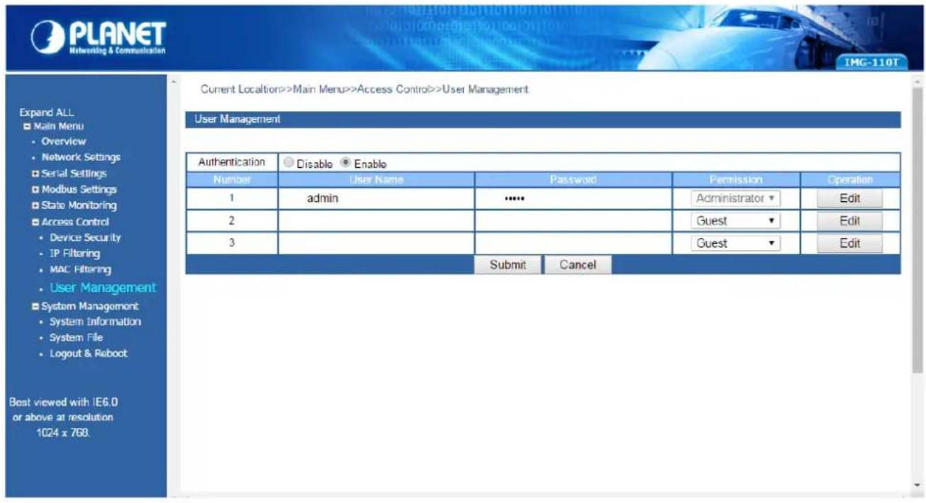
Figure 4-21: Access Control -- User Management Screen
The page includes the following configurable data:
| Authentication | This function provides “Disable” or “Enable” the authentication function. |
| Number | Indicate the number from 1 to 3 for user management items. |
| User Name | Display the current user name information. |
| Password | Display the current password length. |
| Permission | This function provides “Administrator” or “Guest” for the access permission.Guest only views the Industrial Modbus gateway state and only the system administrator can configure the parameters of the Industrial Modbus Gateway. |
| Operation | This function provides editing the current username and password setting; the available range is 20 letters. |
Buttons
Edit
: Click to edit the username and password.
Confirm
: Click to apply changes.
Submit
Click to apply changes.
4.8 System Management
This function provides access control parameters of Industrial Modbus Gateway, including:
-System Information
-System File
-Logout & Reboot
4.8.1 System Information
This function allows editing the system information of Industrial Modbus Gateway. Press the "Submit" button to apply the setting as the screen in Figure 4-22 appears.
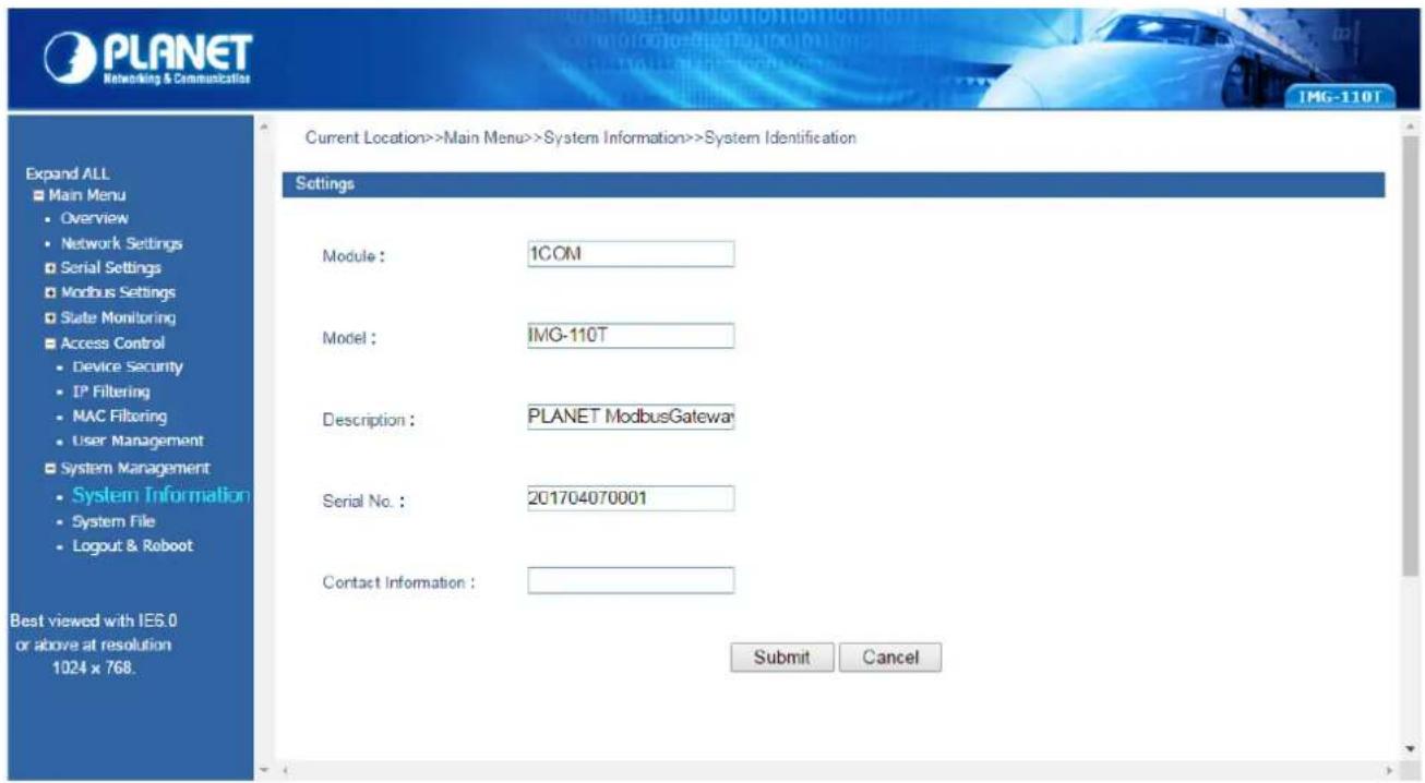
Figure 4-22: System Management --sSystem Information Screen
The page includes the following configurable data:
| Module | This function provides inputting the module information and the available range is 18 letters. |
| Model | This function provides inputting the model information and the available range is 18 letters. |
| Description | This function provides inputting the description and the available range is 18 letters. |
| Serial Number | This function provides inputting the serial number information and the available range is 20 numbers. |
| Contact Information | This function provides inputting the contact information and the available range is 20 letters. |
Button
Submit
Click to apply changes.
4.8.2 System File
This function allows setting up the factory default/Configuration backup and restore/web firmware upgrade functions of Industrial Modbus Gateway as the screen in Figure 4-23 appears.

Figure 4-23: System Management-System File Screen
The page includes the following configurable data:
| Factory Configuration | |
| Load Factory Default | Press the “Start” button to start factory default process. |
| Upload Configuration File from Local PC | |
| Download Configuration | Press the “Download” button to download the configuration file to local PC. |
| Upload Configuration | Press the “Choose File” to find the configuration file and press the “Upload” button to start the configuration upload process. |
| Upgrade Firmware from Local PC | |
| Update Firmware | Press the “Choose File” to find the firmware file and press the “Upgrade” button to start the firmware upgrade process. |
4.8.3 Logout & Reboot
This function provides setting up system logout function and rebooting system function of Industrial Modbus Gateway as the screen in Figure 4-24 appears.

Figure 4-24: System Management -- Logout & Reboot Screen
The page includes the following configurable data:
| System Logout | This function provides “System Logout” from web interface of Industrial Modbus Gateway. Press the “Start” button to log out the system. |
| Reboot System | This function provides “System Reboot” from web interface of Industrial Modbus Gateway. Press the “Reboot” button to reboot the system. |
5. COMMAND LINE INTERFACE
5.1 Accessing the CLI
When accessing the management interface for the Industrial Modbus Gateway via a remote Telnet connection, the Industrial Modbus Gateway can be managed by entering command keywords and parameters at the prompt. Using the Industrial Modbus Gateway's command line interface (CLI) is very similar to entering commands on an UNIX system.
This chapter describes how to use the Industrial Modbus Gateway Command Line Interface (CLI) via a remote Telnet connection.
5.2 Telnet Login
The following shows how to start up the Remote Telnet Management of the Industrial Modbus Gateway. Note the Industrial Modbus Gateway is configured through an Ethernet connection. Please make sure the manager PC must be set to the same IP subnet address.
For example, the default IP address of the Industrial Modbus Gateway is 192.168.0.100, then the manager PC should be set to 192.168.0.x (where x is a number between 1 and 254, except 100) and the default subnet mask is 255.255.255.0.
Logging in to the Industrail Modbus Gateway
- Access Command Prompt and enter telnet 192.168.0.100 to access the Telnet interface.
- When the following dialog box appears, please enter the default user name and password "admin". The login screen in Figure 5-1 appears.
Default Username: admin
Default Password: admin

Figure 5-1: Telnet Login Screen
- After entering the username and password, the telnet main screen appears as Figure 5-2 shows.
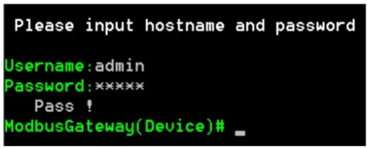
Figure 5-2: Telnet Main Screen of Industrial Modbus Gateway

- For security reason, please change and memorize the new password after this first setup.
- Only accept command in lowercase letter under web interface.
6. COMMAND LINE MODE
The CLI groups all the commands in appropriate modes according to the nature of the command. A sample of the CLI command modes are described below. Each of the command modes supports specific software commands.
After logging in and accessing the Industrial Modbus Gateway Telnet interface, please enter “?” or “help” under Industrial Modbus Gateway Telnet interface where it displays a list of the available commands and descriptions of the commands. The telnet commands list screen appears as Figure 5-3 shows.
| Please input hostname and password | ||
| Username: admin | ||
| Password: ****** | ||
| Pass ! | ||
| ModbusGateway(Device)# ? | ||
| List | --List commands name | |
| Help | --List commands name and help info | |
| Quit | --Quit from CLI | |
| Exit | --Exit from current menu | |
| Reboot | --Reboot device | |
| Serial | <dir> | --Enter serial setting menu |
| Security | <dir> | --Enter security setting menu |
| Manage | <dir> | --Enter system manage menu |
| Information | <dir> | --Enter device information menu |
| Modbus | <dir> | --Enter Modbus manage menu |
| ModbusGateway(Device)# help | ||
| List | --List commands name | |
| Help | --List commands name and help info | |
| Quit | --Quit from CLI | |
| Exit | --Exit from current menu | |
| Reboot | --Reboot device | |
| Serial | <dir> | --Enter serial setting menu |
| Security | <dir> | --Enter security setting menu |
| Manage | <dir> | --Enter system manage menu |
| Information | <dir> | -Enter device information menu |
| Modbus | <dir> | --Enter Modbus manage menu |
| ModbusGateway(Device)# | ||
Figure 6-1: Telnet Help Screen of Industrial Modbus Gateway
The page includes the following configurable data:
| List | List command name under Telnet interface. |
| Help | List command name and help information under Telnet interface. |
| Quit | This command will log out Telnet interface. |
| Exit | This command will exit the current mode and back to the initial mode. |
| Reboot | This command will reboot the Industrial Modbus Gateway. |
| Serial | This command will access serial setup menu. |
| Security | This command will access security setup menu. |
| Manage | This command will access system management menu. |
| Information | This command will access system information setup menu. |
| Modbus | This command will access Modbus setup menu. |
Command lines online help
Description:
Command lines port provides the following online help
Total help
Partial help
Syntax:
Total help
Type in <?> To get all commands and their description.
Example :
ModbusGateway(Device)#?
| List | --List commands name | |
| Help | --List commands name and help info | |
| Quit | --Quit from CLI | |
| Exit | --Exit from current menu | |
| Reboot | --Reboot device | |
| Serial | --Enter serial setting menu | |
| Security | --Enter security setting menu | |
| Manage | --Enter system manage menu | |
| Information | --Enter device information menu | |
| Modbus | --Enter Modbus manage menu |
Type in a command and “?”, between there is a space, if key word is in this location, then type in all keywords and descriptions.
Example :
ModbusGateway(System)# show ?
| mac | --Device MAC address |
| version | --Device version |
| others | --Device name,type,etc |
Partial help
Type in a character string with <?>. It can show all commands beginning with this character string.
Example:
ModbusGateway(Device)# m?
| Manage | <dir> | --Enter system manage menu |
| Modbus | <dir> | --Enter Modbus manage menu |
Type in former letters of some key word of the command, press
Example:
ModbusGateway(Device)# inf +
ModbusGateway(Device)# information
History command
Description:
Command lines port can provide the function similar to Dos key. It automatically saves command lines that users type in, and users can use these history commands.
Syntax:
| Operating | Key | Result |
| Visit previous history command | Up <↑> | When existing earlier command, it is taken out. |
| Visit next history command | Down <↓> | When existing later command, it is taken out. |
APPENDIX A
A.1 Device's RJ45 Pin Assignments
■ 10/100Mbps, 10/100BASE-TX
| Contact MDI | MDI-X | |
| 1 | 1 (TX +) | 3 |
| 2 | 2 (TX -) | 6 |
| 3 | 3 (RX +) | 1 |
| 6 | 6 (RX -) | 2 |
| 4, 5, 7, 8 | Not used | Not used |
Implicit implementation of the crossover function within a twisted-pair cable, or at a wiring panel, while not expressly forbidden, is beyond the scope of this standard.
A.2 RJ45 cable pin assignment

There are 8 wires on a standard UTP/STP cable and each wire is color-coded. The following shows the pin allocation and color of straight cable and crossover cable connection:
| Straight Cable | SIDE 1 | SIDE 2 |
 | 1 = White / Orange | 1 = White / Orange |
| 2 = Orange | 2 = Orange | |
| 3 = White / Green | 3 = White / Green | |
| 4 = Blue | 4 = Blue | |
| 5 = White / Blue | 5 = White / Blue | |
| 6 = Green | 6 = Green | |
| 7 = White / Brown | 7 = White / Brown | |
| 8 = Brown | 8 = Brown | |
| Straight Cable | SIDE 1 | SIDE 2 |
 | 1 = White / Orange | 1 = White / Orange |
| 2 = Orange | 2 = Green | |
| 3 = White / Green | 3 = White / Orange | |
| 4 = Blue | 4 = Blue | |
| 5 = White / Blue | 5 = White / Blue | |
| 6 = Green | 6 = Orange | |
| 12345678 | 7 = White / Brown | 7 = White / Brown |
| 8 = Brown | 8 = Brown |
Figure A-1: Straight-through and Crossover Cable
Please make sure your connected cables are with same pin assignment and color as the above diagram before deploying the cables into your network.
- TRADEMARKS
- DISCLAIMER
- FCC WARNING
- CE MARK WARNING
- ENERGY SAVING NOTE OF THE DEVICE
- WEEE WARNING
- REVISION
- TABLE OF CONTENTS
- INTRODUCTION ....5
- HARDWARE INSTALLATION ....12
- INDUSTRIAL MODBUS GATEWAY MANAGEMENT ....16
- WEB MANAGEMENT ....43
- COMMAND LINE INTERFACE....66
- COMMAND LINE MODE....67
- APPENDIX A....70
- INTRODUCTION
- 1.1 PACKAGE CONTENTS
- 1.2 HOW TO USE THIS MANUAL
- SECTION 2, HARDWARE INSTALLATION
- SECTION 3, INDUSTRIAL MODBUS GATEWAY MANAGEMENT
- SECTION 4, WEB MANAGEMENT
- SECTION 5, COMMAND LINE INTERFACE
- SECTION 6, COMMAND LINE MODE
- APPENDIX A
- 1.3 PRODUCT DESCRIPTION
- ECONOMIC SOLUTION FOR INDUSTRIAL MODBUS TCP/RTU/ASCII NETWORK INTEGRATION
- MODBUS TCP/IP FOR MODBUS RTU/ASCII NETWORK ENVIRONMENT DEPLOYMENT
- REMOTE MANAGEMENT
- MODBUS SERIAL PORT STATE MONITORING
- STABLE PERFORMANCE IN HARDENED ENVIRONMENT DESIGN
- 1.4 APPLICATIONS
- RTU/ASCII MASTER TO MULTI MODBUS TCP/IP SLAVES
- MULTI MODBUS TCP/IP MASTER TO RTU/ASCII SLAVES
- 1.5 PRODUCT FEATURES
- SERIAL INTERFACE
- ETHERNET INTERFACE
- SERIAL OPERATION MODES
- MANAGEMENT FUNCTION
- HARDWARE
- INDUSTRIAL CASE AND INSTALLATION
- 1.6 PRODUCT SPECIFICATIONS
- HARDWARE INSTALLATION
- 2.1 HARDWARE DESCRIPTION
- 2.1.1 PRODUCT LAYOUT
- 2.1.2 LED INDICATORS
- LED DEFINITION
- 10/100BASE-TX INTERFACE
- RS422/RS485 SERIAL PORT
- 2.1.3 2-CONTACT TERMINAL BLOCK PIN DEFINE
- WIRING THE POWER INPUTS
- 2.1.4 5-CONTACT TERMINAL BLOCK PIN DEFINE
- SERIAL PORT CONNECTION
- 2.1.5 HARDWARE DIP SWITCH FOR RESET TO DEFAULT
- RESETTING TO DEFAULT THROUGH HARDWARE DIP SWITCH
- INDUSTRIAL MODBUS GATEWAY MANAGEMENT
- 3.1 OVERVIEW
- 3.2 REQUIREMENTS
- ETHERNET PORT CONNECTION
- 3.3 MANAGEMENT METHODS
- 3.3.1 WEB MANAGEMENT INTERFACE
- 3.3.2 LOGIN THE INDUSTRIAL MODBUS GATEWAY WEB INTERFACE
- LOGGING IN TO THE INDUSTRAIL MODBUS GATEWAY
- 3.3.3 REMOTE IP-BASED TELNET INTERFACE
- 3.3.4 LOGIN THE INDUSTRIAL MODBUS GATEWAY TELNET INTERFACE
- 3.4 PLANET SMART DISCOVERY UTILITY
- 3.5 PLANET MODBUS GATEWAY UTILITY
- 3.5.1 INSTALLING PLANET MODBUS GATEWAY UTILITY
- 3.5.2 PLANET MODBUS GATEWAY UTILITY MENU BAR
- 3.5.2.1 SYSTEM(S)
- SELECT NETWORK ADAPTER
- QUIT
- 3.5.2.2 TOOLS(Y)
- SEARCH DEVICE
- SET SEARCH TYPE
- SET TIMING SAVE
- MANUAL ADD DEVICE
- BATCH IP SETTINGS
- 3.5.3 PLANET MODBUS GATEWAY UTILITY SHORTCUT MENU BAR
- 3.5.3.1 USER MANAGER
- BUTTON
- 3.5.3.2 IMPORT NETWORK TOPOLOGY
- 3.5.3.3 EXPORT NETWORK TOPOLOGY
- 3.5.3.4 ZOOM IN
- 3.5.3.5 ZOOM OUT
- 3.5.3.6 SEARCH DEVICE
- 3.5.3.7 SAVE TOPOLOGY
- 3.5.3.8 DELETE TOPOLOGY
- 3.5.3.9 BATCH IP SETTINGS
- 3.5.3.10 BATCH MONITORING IP SETTINGS
- 3.5.3.11 HIDE DEVICE TREE/ SHOW DEVICE TREE
- 3.5.3.12 HIDE ALARM LIST/ SHOW ALARM LIST
- 3.5.3.13 AUTO REFRESH TOPOLOGY
- 3.5.3.14 REFRESH INTERVAL
- 3.5.4 PLANET MODBUS GATEWAY UTILITY DEVICE FUNCTION
- 3.5.4.1 WEB CONSOLE
- 3.5.4.2 DEVICE NAME
- 3.5.4.3 NETWORK SETTINGS
- 3.5.4.4 RESET FACTORY SETTINGS
- 3.5.4.5 RECENT ALARM
- WEB MANAGEMENT
- 4.1 WEB MAIN PAGE
- 4.2 OVERVIEW
- 4.3 NETWORK SETTINGS
- SUBMIT
- 4.4 SERIAL SETTINGS
- 4.4.1 COM SETTINGS
- 4.4.2 COM INFORMATION
- 4.5 MODBUS SETTINGS
- 4.5.1 MODBUS PARAMETERS
- 4.5.2 SLAVE ID
- BUTTONS
- AFFIRM
- DELETE
- MODIFY
- RTU MASTER MODE
- RTU SLAVE MODE
- ASCII MASTER MODE
- ASCII SLAVE MODE
- 4.6 STATE MONITORING
- 4.6.1 COM STATE
- 4.7 ACCESS CONTROL
- 4.7.1 DEVICE SECURITY
- 4.7.2 IP FILTERING
- 4.7.3 MAC FILTERING
- 4.7.4 USER MANAGEMENT
- EDIT
- CONFIRM
- 4.8 SYSTEM MANAGEMENT
- 4.8.1 SYSTEM INFORMATION
- 4.8.2 SYSTEM FILE
- 4.8.3 LOGOUT & REBOOT
- COMMAND LINE INTERFACE
- 5.1 ACCESSING THE CLI
- 5.2 TELNET LOGIN
- COMMAND LINE MODE
- COMMAND LINES ONLINE HELP
- DESCRIPTION
- TOTAL HELP
- PARTIAL HELP
- SYNTAX
- EXAMPLE
- HISTORY COMMAND
- A.1 DEVICE'S RJ45 PIN ASSIGNMENTS
- A.2 RJ45 CABLE PIN ASSIGNMENT
Brand : Planet
Model : IMG-110T
Category : Modbus Gateway