
KSG110B - Flat Panel Mount Chief - Free user manual and instructions
Find the device manual for free KSG110B Chief in PDF.


| Product Type | Flat Panel Mount |
| Brand | Chief |
| Model | KSG110B |
| Compatible VESA Patterns | Up to 600x400 mm |
| Weight Capacity | Up to 150 lbs (68 kg) |
| Mounting Type | Fixed (low profile) |
| Panel Size Supported | 32" to 70" |
| Material | Heavy-gauge steel |
| Finish | Black powder coat |
| Dimensions (W x H x D) | 26.3 x 18.5 x 1.5 in (668 x 470 x 38 mm) |
| Weight | 12.5 lbs (5.7 kg) |
| Power Source | Not applicable (mechanical mount) |
| Installation | Wall mount, requires drilling into studs |
| Included Hardware | Mounting brackets, screws, bolts, and spacers |
| Cleaning Instructions | Wipe with a damp cloth; do not use abrasive cleaners |
| Safety Features | Security screws and locking knobs to prevent theft |
| Spare Parts Availability | Contact Chief customer support or authorized dealers |
| Repairability | Professional installation recommended; no user-serviceable parts |
| Warranty | Limited lifetime warranty |
| Compliance | UL Listed |
Frequently Asked Questions - KSG110B Chief
User questions about KSG110B Chief
0 question about this device. Answer the ones you know or ask your own.
Ask a new question about this device
Download the instructions for your Flat Panel Mount in PDF format for free! Find your manual KSG110B - Chief and take your electronic device back in hand. On this page are published all the documents necessary for the use of your device. KSG110B by Chief.
USER MANUAL KSG110B Chief
INSTALLATION INSTRUCTIONS

natural_image
Technical line drawing of a mechanical assembly with mounting flanges and housing (no text or symbols)Universal Slat Wall Dual Arm Mounts
DISCLAIMER
Milestone AV Technologies and its affiliated corporations and subsidiaries (collectively "Milestone"), intend to make this manual accurate and complete. However, Milestone makes no claim that the information contained herein covers all details, conditions or variations, nor does it provide for every possible contingency in connection with the installation or use of this product. The information contained in this document is subject to change without notice or obligation of any kind. Milestone makes no representation of warranty, expressed or implied, regarding the information contained herein. Milestone assumes no responsibility for accuracy, completeness or sufficiency of the information contained in this document.
Chief® is a registered trademark of Milestone AV Technologies. All rights reserved.

IMPORTANT WARNINGS AND
CAUTIONS!

WARNING: A WARNING alerts you to the possibility of serious injury or death if you do not follow the instructions.

CAUTION: A CAUTION alerts you to the possibility of damage or destruction of equipment if you do not follow the corresponding instructions.

WARNING: Failure to read, thoroughly understand, and follow all instructions can result in serious personal injury, damage to equipment, or voiding of factory warranty! It is the installer's responsibility to make sure all components are properly assembled and installed using the instructions provided.

WARNING: Failure to provide adequate structural strength for this component can result in serious personal injury or damage to equipment! It is the installer's responsibility to make sure the structure to which this component is attached can support five times the combined weight of all equipment. Reinforce the structure as required before installing the component.

WARNING: Exceeding the weight capacity can result in serious personal injury or damage to equipment! It is the installer's responsibility to make sure the combined weight of all components located between the supporting structure and mount does not exceed the 40 lbs (18.14 kg).
DIMENSIONS
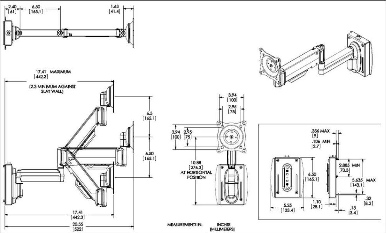
LEGEND
 | Tighten Fastener |
| Apretar elemento de fijación | |
| Befestigungsteil festziehen | |
| Apertar fixador | |
| Serrare il fissaggio | |
| Bevestiging vastdraaien | |
| Serrez les fixations | |
 | Loosen Fastener |
| Aflojar elemento de fijación | |
| Befestigungsteil lösen | |
| Desapertar fixador | |
| Allentare il fissaggio | |
| Bevestiging losdraaien | |
| Desserrez les fixations | |
 | Adjust |
| Ajustar | |
| Einstellen | |
| Ajustar | |
| Regolare | |
| Afstellen | |
| Ajuster |

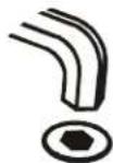
TOOLS AND PARTS FOR INSTALLATION

INSTALLATION

WARNING: FAILURE TO PROVIDE ADEQUATE STRUCTURAL STRENGTH FOR THIS COMPONENT CAN RESULT IN SERIOUS PERSONAL INJURY OR DAMAGE TO EQUIPMENT! It is the installer's responsibility to make sure the structure to which this component is attached can support five times the combined weight of all equipment. Reinforce the structure as required before installing the component.
- Install the slat wall bracket (B) following the instructions included with kit.
IMPORTANT ! : If the display being installed has a recessed mounting surface, the display must be assembled to the mount prior to mount installation. See Display Installation in this document before proceeding.
- Insert top of mount (A) over lip on top of wall bracket (B). (See Figure 1)

Figure 1
- Swing mount (A) down flush against wall bracket (B). (See Figure 2)

Figure 2
- Tighten set screw using 5/32" hex key (D). (See Figure 3)

CAUTION: IMPROPER INSTALLATION CAN LEAD TO DISPLAY FALLING CAUSING SERIOUS PERSONAL INJURY OR DAMAGE TO EQUIPMENT! Make sure set screw engages back side of mounting dish on wall bracket (B). (See Figure 3)

Figure 3
DISPLAY INSTALLATION
The mounting holes on the back of the display will be flush with the back surface, or recessed into the back. Refer to the applicable installation procedure below.
Swing Arm Flush Display Installation

CAUTION: IMPROPER INSTALLATION CAN LEAD TO DISPLAY FALLING CAUSING SERIOUS PERSONAL INJURY OR DAMAGE TO EQUIPMENT! Using screws of improper size may damage your display! Proper screws will easily and completely thread into display mounting holes.

CAUTION: IMPROPER INSTALLATION CAN LEAD TO DISPLAY FALLING CAUSING SERIOUS PERSONAL INJURY OR DAMAGE TO EQUIPMENT! Inadequate thread engagement in display may cause display to fall! Back out screws ONLY as necessary to allow installation of Centris bracket!
- Ensure Centris cup is able to swivel and tilt easily, yet still be tight enough to hold display in desired position. Adjust as required before proceeding. See "ADJUSTMENT" for detail.
- Using Phillips screwdriver, carefully install two screws (G1) into the upper mounting holes on the display. Thread screws completely into display, then back out 3 complete turns.
- Align two screws (G1) (installed on the back of the display in the previous step) with the two top teardrop mounting holes on the Centris cup.

CAUTION: IMPROPER INSTALLATION CAN LEAD TO DISPLAY FALLING CAUSING SERIOUS PERSONAL INJURY OR DAMAGE TO EQUIPMENT! Smaller area of teardrop mounting holes must be facing downward for proper installation. Reposition Centris cup if required.

Figure 4
- Using Phillips screwdriver, install two screws (G1) through the lower mounting holes in Centris cup into the display.
- Tighten all screws (G1). Do not overtighten!
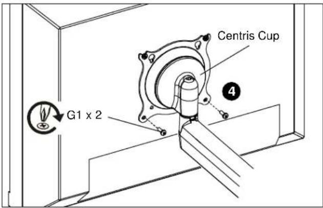
Figure 5
6. Proceed to "CABLE MANAGEMENT."
Swing Arm Recessed Display Installation
-
Ensure Centris bracket is able to swivel and tilt easily, yet still be tight enough to hold display in desired position. Adjust as required before proceeding. See "ADJUSTMENT" for detail.
-
Carefully place display face down on a clean and dry surface.
-
Determine depth of recessed mounting holes relative to back surface of display.
-
Select proper length spacer and screw from table below:
IMPORTANT ! : All spacers used should be the same length. If the recess depths result in multiple spacer lengths, then select the longer spacer.
| IF recess DEPTH is: THEN use spacer: AND screw: | ||
| 3/8" or less G4 (3/8" long) G2 (G4 x 20mm) | ||
| More than 3/8" up to and including 3/4" | G5 (3/4" long) G3 (G4 x 30mm) | |
- Place the four (G4 or G5) spacers over each mounting hole on the back of display. (See Figure 6)
- Orient mount so that mounting holes in the Centris cup are aligned with the holes in the spacers (G4 or G5); rotate the Centris cup as required (See Figure 6).

CAUTION: IMPROPER INSTALLATION CAN LEAD TO DISPLAY FALLING CAUSING SERIOUS PERSONAL INJURY OR DAMAGE TO EQUIPMENT! Using screws of improper size may damage your display! Proper screws will easily and completely thread into display mounting holes.
- Using Phillips screwdriver, install four screws (G2 or G3) through the mounting holes in Centris cup, through the spacers (G4 or G5), into display (See Figure 6).
- Tighten all four screws. Do not overtighten!
- Return to mount installation section to continue.

Figure 6
Cable Management
- Attach all cables to display.
- Open the cable management bracket by sliding it towards the edge of the arm (See Figure 7).
NOTE: If necessary, cable management bracket attach screws may be loosened using 3/32" hex key (H).

Figure 7

CAUTION: Ensure that adequate cable slack exists for movement of display, and that cables will not be pinched when bracket is closed.
- Carefully insert cables into bracket (See Figure 8).

Figure 8
- Close cable management bracket by sliding it back towards the centerline of the arm (See Figure 7).
NOTE: If necessary, cable management bracket attach screws may be tightened using 3/32" hex key (H).

CAUTION: Ensure that adequate cable slack exists for movement of display, and that cables will not be pinched by installation of cover (E) or screws (F).
-
Carefully insert cables in cavity located in lower portion of mount arm (See Figure 9).
-
Using Phillips screwdriver, install cover (E) with two screws (F).
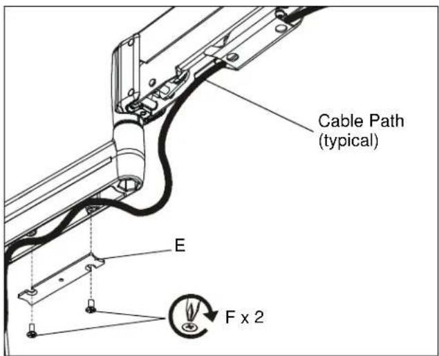
Figure 9
Installation is complete.
Adjustments
Centris Head Tension Adjustment
-
If previously attached, disconnect cables from display, remove display.
-
Using Phillips screwdriver, slightly loosen or tighten the adjustment screw as necessary (See Figure 10).

Figure 10
- Reinstall display. See Display Installation in this document.
Display Adjustment
Lateral position on display:
- Using your fingers, slightly loosen adjustment knob "A". (See Figure 11)
- Slide display to desired position.
- Using your fingers, tighten adjustment knob "A". (See Figure 11)
PITCH / YAW / ROLL Tension
- Using your fingers, slightly loosen adjustment knob "B". (See Figure 11)
- Adjust display as desired.
- Using your fingers, tighten adjustment knob "B".

Figure 11
Swing Arm Tension
- Using 3/16" hex wrench (C), loosen or tighten adjustment screw(s) as necessary (See Figure 12).

Figure 12
Installation Instructions
- INSTALLATION INSTRUCTIONS
- Universal Slat Wall Dual Arm Mounts
- DISCLAIMER
- IMPORTANT WARNINGS AND
- CAUTIONS!
- DIMENSIONS
- INSTALLATION
- DISPLAY INSTALLATION
- Swing Arm Flush Display Installation
- Swing Arm Recessed Display Installation
- Cable Management
- Adjustments
- Centris Head Tension Adjustment
- Display Adjustment
- Lateral position on display:
- PITCH / YAW / ROLL Tension
- Swing Arm Tension
Brand : Chief
Model : KSG110B
Category : Flat Panel Mount