
99-7320 - Assembly kits Metra - Free user manual and instructions
Find the device manual for free 99-7320 Metra in PDF.


| Product Type | Mounting Kit |
| Brand | Metra |
| Model | 99-7320 |
| Compatibility | Select Ford/Mercury vehicles (1998-2002 Ford Escort, Mercury Tracer) |
| Color | Black, textured finish |
| Material | High-quality ABS plastic |
| Dimensions (W x H x D) | 7.5 x 4.5 x 1.0 inches |
| Weight | 0.45 lbs (200 g) |
| Radio Size Supported | Single-DIN or Double-DIN with separate pocket |
| Installation Hardware Included | Brackets, screws, and trim ring |
| Installation Difficulty | Easy to moderate, DIY-friendly |
| Tools Required | Trim removal tools, screwdrivers (Phillips and flathead) |
| Maintenance | Wipe with dry cloth; avoid harsh chemicals |
| Safety | Follow vehicle manufacturer's instructions for airbag systems |
| Spare Parts Availability | Contact Metra or authorized dealers for replacement brackets |
| Warranty | 1-year limited warranty against defects |
Frequently Asked Questions - 99-7320 Metra
User questions about 99-7320 Metra
0 question about this device. Answer the ones you know or ask your own.
Ask a new question about this device
Download the instructions for your Assembly kits in PDF format for free! Find your manual 99-7320 - Metra and take your electronic device back in hand. On this page are published all the documents necessary for the use of your device. 99-7320 by Metra.
USER MANUAL 99-7320 Metra
INSTALLATION INSTRUCTIONS FOR PART 99-7320
APPLICATIONS Hyundai Sonata 2006-2008
99-7320
KIT FEATURES
• DIN head unit provision

natural_image
Interior view of a car dashboard with air vent, grille, and control panel (no visible text or symbols)KIT COMPONENTS
A) Radio Housing

natural_image
Technical line drawing of a mechanical component with no visible text or symbolsWIRING AND ANTENNA CONNECTIONS (Sold Separately)
Harness:
• 70-5520 - Ford harness 2003-up
Antenna Adapter:
- Not required
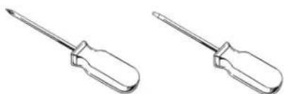
TOOLS REQUIRED:
Phillips Screwdriver
- Small Flat Blade Screwdriver
natural_image
Two identical screwdriver illustrations shown in side profile (no text or symbols)
1-800-221-0932

www.metraonline.com
© COPYRIGHT 2004-2009
METRA ELECTRONICS CORPORATION
TABLE OF CONTENTS
Dash Disassembly ....1
Kit Assembly 2
Final Assembly 3

KNOWLEDGE IS POWER
Enhance your installation and fabrication skills by enrolling in the most recognized and respected mobile electronics school in our industry.
Log onto www.installerinstitute.com or call 800-354-6782 for more information and take steps toward a better tomorrow.
HYUNDAI SONATA 2006-2008
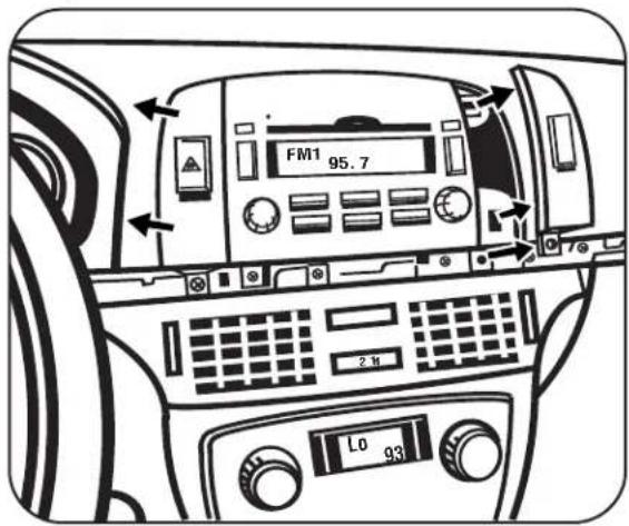
1 Disconnect the negative battery terminal to prevent an accidental short circuit.
2 Open glove box and remove (2) Phillips screws from top edge of glove box opening and bottom edge of wood trim below radio. (Figure A)
3 Unclip and remove wood trim from below radio and above glove box. (Figure B)
4 Remove (1) Phillips screw per side panel next to radio then unclip and remove panels. (Figure C)
5 Remove (6) Phillips screws from radio to extract from sub dash. (Figure D)
D

A

natural_image
Illustration of a hand using a screwdriver to adjust or install a car interior panel (no text or symbols visible)B

natural_image
Interior view of a car dashboard with controls and a hand adjusting the dashboard (no text or symbols visible)C
DIN HEAD UNIT PROVISION
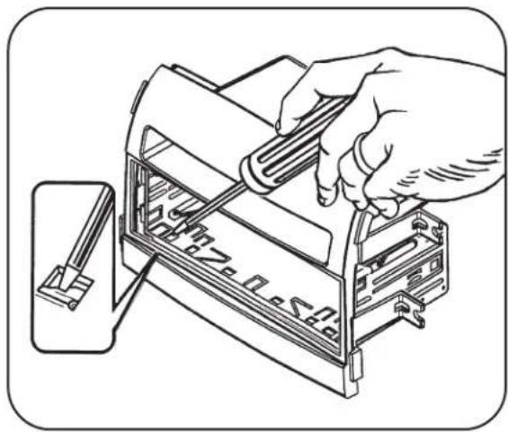
1 Slide the DIN cage into the Radio Housing and secure by bending the metal locking tabs down. (Figure A)
2 Slide the aftermarket head unit into the cage and secure. (Figure B)
A
natural_image
Line drawing of a hand using a computer to press or install a device into a rack (no text or symbols visible)B

natural_image
Technical line drawing of a printer or scanner device with no visible text or symbolsFINAL ASSEMBLY
1 Locate the factory wiring harness in the dash and make the connection as shown. Metra recommends using the proper mating adapter and making the connections as shown. (Isolate and individually tape off the ends of any unused wires to prevent electrical short circuit.)
2 Re-connect the negative battery terminal and test the unit for proper operation.
3 Reassemble radio and dash assemblies in reverse order of disassembly.
FINAL WIRING CONNECTIONS
Make wiring connections using the EIA color code chart shown below and the instructions included with the head unit. Metra recommends making connections as shown below; Strip, Splice, Solder, Tape. Isolate and individually tape off ends of any unused wires to prevent electrical short circuit.

A) Strip wire ends back 1/2"
B) Twist ends together
C) Solder
D) Tape
METRA / EIA WIRING CODE
12V Ignition / Acc ... Red
12V Batt / Memory .. Yellow
Ground .... Black*
Power Antenna ..... Blue
Amp Turn-On ..... Blue / White
Amp Ground ..... Black / White
Illumination.....Orange
Dimmer ..... Orange / White
Right Front (+) ..... Gray
Right Front (-)..... Gray / Black
Left Front (+) ..... White
Left Front (-) ..... White / Black
Right Rear (+).....Violet
Right Rear (-) ..... Violet / Black
Left Rear (+).... Green
Left Rear (-) ..... Green / Black
*NOTE: When Black a wire is not present, ground radio to vehicle chassis.
All colors may not be present on all leads due to manufacturer's specifications.
NOTES
NOTES
99-7320 INSTRUCTIONS
Brand : Metra
Model : 99-7320
Category : Assembly kits