
ZCM620X - Kitchen ZANUSSI - Free user manual and instructions
Find the device manual for free ZCM620X ZANUSSI in PDF.


| Product Type | Freestanding gas cooker |
| Brand | Zanussi |
| Model | ZCM620X |
| Dimensions (H x W x D) | 900 mm x 597 mm x 595 mm |
| Weight | Approximately 60 kg |
| Power Supply | 230-240 V ~ 50 Hz, 2.320 kW total |
| Gas Supply | Natural Gas G20 20 mbar (convertible to LPG) |
| Oven Capacity | 1.8 cu. ft (approx. 51 litres) |
| Hob Burners | 4 gas burners: 1 rapid (3.0 kW), 2 semi-rapid (2.0 kW each), 1 auxiliary (1.0 kW) |
| Oven Functions | Conventional, fan cooking, grill, defrost |
| Oven Heating Elements | Top 1.055 kW, bottom 1.250 kW, convection 2.080 kW, grill 1.880 kW |
| Oven Light | 15 W, replaceable with high-temperature bulb (300°C, E14, 230-240 V) |
| Timer | 24-hour electronic clock with minute minder, cooking duration, and end-of-cooking function |
| Shelf Levels | 4 levels, 2 shelves supplied |
| Storage Drawer | Underneath oven cavity |
| Splashback | Stainless steel, included and fitted to rear edge |
| Cleaning | Enamel oven cavity, removable burner caps and crowns, pan supports dishwasher safe |
| Safety Features | Child safety warnings, stability bracket required, oven door protection device optional |
| Warranty | 12 months peace of mind, European guarantee |
| Installation | Must be installed by CORGI registered installer, requires ventilation |
Frequently Asked Questions - ZCM620X ZANUSSI
User questions about ZCM620X ZANUSSI
0 question about this device. Answer the ones you know or ask your own.
Ask a new question about this device
Download the instructions for your Kitchen in PDF format for free! Find your manual ZCM620X - ZANUSSI and take your electronic device back in hand. On this page are published all the documents necessary for the use of your device. ZCM620X by ZANUSSI.
USER MANUAL ZCM620X ZANUSSI
You MUST read these warnings carefully before installing or using the appliance. If you need assistance, contact our Customer Care Department on 08705 727727
Installation
- This cooker must be installed by qualified personnel, according to the manufacturer's instructions and to the relevant British Standards.
- This cooker is heavy. Take care when moving it.
- Any gas installation must be carried out by a registered CORGI installer.
- Remove all packaging before using the cooker.
- Ensure that the gas and electrical supply complies with the type stated on the rating plate, located near the gas supply pipe.
- Do not attempt to modify the cooker in any way.
Child Safety
- This cooker is designed to be operated by adults. Do not allow children to play near or with the cooker.
- The cooker gets hot when it is in use. Children should be kept away until it has cooled.
- Children can also injure themselves by pulling pans or pots off the cooker.
During Use
- This cooker is intended for domestic cooking only. It is not designed for commercial or industrial purposes.
- When in use a gas cooker will produce heat and moisture in the room in which it has been installed. Ensure there is a continuous air supply, keeping air vents in good condition or installing a cooker hood with a venting hose.
- When using the cooker for a long period time, the ventilation should be improved, by opening a window or increasing the extractor speed.
- Do not use this cooker if it is in contact with water. Do not operate the cooker with wet hands.
-
Ensure the control knobs are in the 'OFF' position when not in use.
-
When using other electrical appliances, ensure the cable does not come into contact with the hot surfaces of the cooker.
- Unstable or misshapen pans should not be used on the hob burners as unstable pans can cause an accident by tipping or spillage.
- Never leave the cooker unattended when cooking with oil and fats.
- This cooker should be kept clean at all times. A build-up of fats or foodstuffs could result in a fire.
- Never use plastic dishes in the oven or on the hob burners. Never line any part of the oven with aluminium foil.
• Always ensure that the oven vent which is located at the centre back of the hob is left unobstructed to ensure ventilation of the oven cavity. - Perishable food, plastic items and areosols may be affected by heat and should not be stored above the cooker.
Service
- This cooker should only be repaired or serviced by an authorised Service Engineer and only genuine approved spare parts should be used.
Environmental Information
• After installation, please dispose of the packaging with due regard to safety and the environment.
- When disposing of an old appliance, make it unusable, by cutting off the cable.
Keep this instruction book for future reference and ensure it is passed on to any new owner.
Contents
For the User
Important Safety Information...... 2
Description of the Cooker...... 4
Control Panel 5
The Oven Cavity....5
Accessories ....5
Operation 6
Controls 6
Hob burners 6
Electric Oven 7
24 hour Clock and Timer 7
Before the First Use of the Cooker ..... 10
Using the Oven 10
Using the Conventional Oven 12
Cooking Chart 13
Using the Fan Oven 14
Cooking Chart 15
Roasting Chart 15
Defrosting 17
Grilling.... 18
Maintenance and Cleaning.... 19
Cleaning the Oven 20
Something Not Working 22
Service and Spare Parts 23
Peace of Mind for 12 Months .... 23
Guide to Use the instructions
The following symbols will be found in the text to guide you throughout the Instructions:

Safety Instructions

Step by step instructions for an operation

Hints and Tips
For the Installer
Instructions for the Installer .... 24
Important Safety Requirements...... 25
Installation.... 26
Electrical connections 28
Commissioning.... 29
Conversion from Natural Gas to LPG.. 30
Oven Door Protection Device
(Model ZCM 620 X)
All our appliances comply with the European safety standards. Nevertheless, in order to ensure the highest safety level, and avoid small children to be exposed to the heat when the appliance is operated, it is possible to fit a special protection device to the oven door. This device can be purchased in our Service Force Centres, specifying the relevant code (35791) and the Product No. shown on the rating plate.

This appliance is manufactured according to the following EEC directives:
73/23 EEC - 90/683 EEC - 93/68 EEC - 89/336 EEC - 90/396 EEC,
current edition.
Description of the Cooker
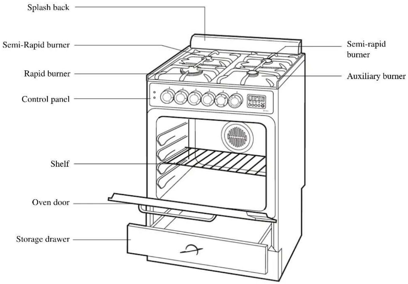
natural_image
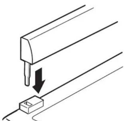
Pure electrical circuit lines without any symbolsFitting the Splash back
A stainless steel splash back is supplied with the appliance. This is meant to be fitted on the rear edge of the cooker's hob. The splash back package is in the oven cavity.
-
Unpack the splash back and dispose of the packaging with due regard to safety and the environment.
-
Slide the two bayonets of the splash back into the relevant supports on the rear edge of the cooker's hob.
Control Panel

- Cooker Operation Pilot Light
- Oven Thermostat Pilot Light
- Electric ignition push button
- Back left burner control knob (semi-rapid)
- Front left burner control knob (rapid)
- Front right burner control knob (auxiliary)
- Back right burner control knob (semi-rapid)
- Oven function control knob
- Oven thermostat control knob
10.24 hour clock and Programmer
The Oven Cavity

Accessories

Operation
INSTALLATION

Any gas installation must be carried out by a registered CORGI installer, and in accordance with existing rules and regulations.
The relevant instructions are to be found in the second section of this manual.
Please ensure that when the appliance is installed, it is easily accessible for the engineer in the event of a breakdown.
WHEN THE COOKER IS FIRST INSTALLED

Once the cooker has been installed, it is important to remove any protective materials, which were put on in the factory.
Controls
Hob burners
To light a burner, turn the relevant control knob anticlockwise to maximum position. At the same time push the electric ignition button which is marked with a little spark.. Then adjust the flame as required. If the burner does not ignite, turn the control knob to zero, and try again.

When switching on the mains, after installation or a power cut, it is quite normal for the spark generator to be activated automatically.
To ensure maximum burner efficiency, you should only use pots and pans with a flat bottom fitting the size of the burner used (see table).
| Burner minimum maximum diameter diameter | ||
| Large (rapid) 160 mm. | 240 mm. | |
| Medium (semi-rapid) | 120 mm. 220 mm. | |
| Small (Auxiliary) 80 | mm. 160 mm. | |

If you use a saucepan which is smaller than the recommended size, the flame will spread beyond the bottom of the pan, causing the handle to overheat.

As soon as a liquid starts boiling, turn down the flame so that it will barely keep the liquid simmering.

Take care when frying food in hot oil or fat, as the overheated splashes could easily ignite.

If the control knobs become difficult to turn, please contact your local Zanussi Service Centre.
Electric Oven
Oven Function Control Knob
Oven Light - The oven light will be on without any cooking function
☐ Conventional cooking - The heat comes from both the top and bottom element, ensuring even heating inside the oven.
Fan cooking - This allows you to roast or roast and bake simultaneously using any shelf, without flavour transference.
Grill - The heat comes only from the top element.
Thermostat Control Knob
Turn the thermostat control knob clockwise to select temperatures between 50°C and 250°C (MAX).


24 hour Clock and Timer
Minute minder
Cooking duration
STOP End of cooking time
Manual function
Cookpot symbol - This will be displayed when a program is in operation.
Auto symbol - This will be displayed when the oven has been programmed for automatic operation.
Time setting knob - Turn it clockwise and hold it in the turned position to increase the time setting. Turn it anticlockwise and hold it in the turned position to decrease the time setting. The count-up or count-down speed increases the longer the knob is held in the turned position.

The electronic timer can indicate the time of day, operate as a minute minder and automatically operate the oven.
Before the oven can be operated, the time of day must be set on the electronic timer.
Please note that this is a 24 hour clock. For example, 2pm is shown as 14:00.
In case of loss of power, all the settings (time of day, set program or program in operation), will be cancelled. When the power is restored, the numbers on the display will flash, and the timer has to be reset.

TO SET THE TIME OF DAY
Press button 🎨 and at the same time turn the time setting knob until the correct time of day is displayed.

TO SET THE MINUTE MINDER
Press button and at the same time turn the setting time knob until the duration time is displayed (maximum 23 hours, 59 minutes).
Our diagram shows the timer set for 45 minutes. After a few seconds the time of day will show in the display.
To check the number of minutes remaining, press the
button. At the end of the timed period an alarm will sound. To switch off the alarm press button 🎨.

MANUAL FUNCTION
Press button 🤨 to set the oven for manual function.


TO SET THE TIMER TO SWITCH OFF ONLY
This is useful if you want to begin cooking immediately but have the oven switch off automatically.
- Set the oven function control knob and the thermostat control knob on the required settings.
- Place food in the oven.
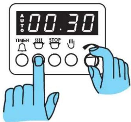
- Press button 📋 and, at the same time, turn the time setting knob until the required cooking duration is displayed.
Our diagram shows the timer set for 30 minutes. At the end of the cooking time the oven will switch off, an alarm will sound. To switch off the alarm press button ⏻. Ensure the oven function control knob and the thermostat control knob are in the OFF position.

TO SET THE TIMER TO SWITCH THE OVEN ON AND OFF
-
Ensure the clock is showing the right time of day.
-
Carry out steps 1, 2 and 3 as explained in "To set the timer to switch off only".
-
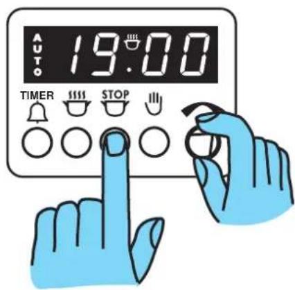
Press button STOP and at the same time turn the time setting knob until the end cooking time is displayed. Our diagram shows the end cooking time set for 7.00 pm.
-
The oven will switch on and off automatically. The end of cooking will be marked by an acoustic alarm. To switch off the alarm press button 🎨. Ensure the oven function control knob and the thermostat control knob are in the OFF position.

TO CANCEL A PROGRAMME
Press button 🎨 Any set program or program in operation will be cancelled and the timer will revert to manual function. Ensure the oven function control knob and the thermostat control knob are in the OFF position.
Before the First Use of the Cooker

Remove all packaging, both inside and outside the cooker, before using it.
Before first use, the oven should be heated without food. During this time, an unpleasant odour may be emitted. This is quite normal.

- Set the electronic programmer to manual function.
- Switch the oven function control knob to conventional cooking ☐.
- Set the thermostat control knob to MAX.
- Open a window for ventilation.
- Allow the oven to run empty for approximately 45 minutes.
- Half way through, reset the oven function control to fan cooking ♿.
This procedure should be repeated with the grill √ function for approximately 5-10 minutes.
Using the Oven

• Always cook with the oven door closed.
- Stand clear when opening the drop down oven door. Do not allow it to fall open - support the door using the door handle, until it is fully open.

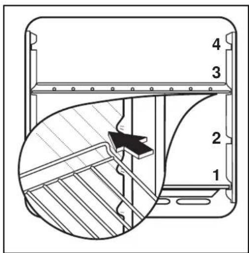
• The oven has four shelf levels, and is supplied with two shelves.
The shelf positions are counted from the bottom of the oven as shown in the diagram.
It is important that these shelves are correctly positioned as shown in the diagram.
- Do not place cookware directly on the oven base.
i Hints and Tips
Condensation and steam
When food is heated it produces steam in the same way as a boiling kettle. The oven vents allow some of this steam to escape. However, always stand back from the oven when opening the oven door to allow any build up of steam or heat to release.
If the steam comes into contact with a cool surface on the outside of the oven, e.g. a trim, it will condense and produce water droplets. This is quite normal and is not a fault with the oven.
To prevent discoloration, regularly wipe away condensation and also soilage from surfaces.
Cookware
- Use any oven proof cookware which will withstand temperatures of 250^ .
- Baking trays, oven dishes, etc. should not be placed directly against the grid covering the fan at the back of the oven, or placed on the oven base.
- Do not use baking trays larger than 30cm× 35cm (12 in x 14 in) as they will restrict the circulation of heat and may affect performance.
The effects of dishes on cooking results
Dishes and tins vary in their thickness, conductivity, colour, etc. which affects the way they transmit heat to the food inside them.
A Aluminium, earthenware, oven glassware and bright shiny utensils reduce cooking and underneath browning.
B Enamelled cast iron, anodized aluminium, aluminium with non-stick interior and coloured exterior and dark, heavy utensils increase cooking and underneath browning.
Storage Drawer
The storage drawer is located underneath the oven cavity.

During cooking the storage drawer may become hot if the oven is on high for a long period of time, therefore flammable materials such as oven gloves, tea towels, plastic aprons etc. should not be stored in the drawer.
Oven accessories such as baking sheets, will also become hot, therefore care should be taken when removing these items from the drawer whilst the oven is in use or still hot.
Using the Conventional Oven
When using this setting, heat comes from both the top and bottom elements. This allows you to cook on a single level and is particularly suitable for dishes which require extra base browning such as pizzas, quiches and flans.
Gratins, lasagnes and hotpots which require extra top browning also cook well in the conventional oven. This form of cooking gives you the opportunity to cook without the fan in operation.

How to Use the
Conventional Oven
- Turn the oven function control knob to the required cooking function (☐).
- Turn the thermostat control to the required temperature.
THINGS TO NOTE
- The oven light will come on when the oven function control knob is set.
- The thermostat control light will remain on until the correct temperature is reached. It will then cycle on and off to show that temperature is being maintained.

Hints and Tips
The middle shelf position allows for the best heat distribution. To increase base browning simply lower the shelf position. To increase top browning, raise the shelf position.
The material and finish of the baking trays and dishes used will affect base browning. Enamelware, dark, heavy or non-stick utensils increase base browning, while oven glassware, shiny aluminium or polished steel trays reflect the heat away and give less base browning.
Always place dishes centrally on the shelf to ensure even browning.
Stand dishes on suitably sized baking trays to prevent spillage onto the base of the oven and make cleaning easier.
Do not place dishes, tins or baking trays directly on the oven base as it becomes very hot and damage will occur.
For faster preheating use the fan oven function to preheat the oven until the oven indicator neon goes out, then switch the selector to the conventional oven setting.

natural_image
Line drawing of an open oven with a pot and lid, no text or symbols present
natural_image
Line drawing of a cabinet or enclosure with a cross symbol indicating a warning or hazard, no text or symbols present.
Single level cooking gives best results. If you require more than one level cooking use the fan oven function.
Cooking Chart
| Food | Thermostat | Runner | Time Position |
| Biscuits, cookies 170-200 3 25-20 min. | |||
| Bread, yeast doughs 200-230 2 35-45 min. | |||
| Casseroles 140-170 2 90-180 min. | |||
| Small cakes 170-180 2 18-25 min. | |||
| Cakes Madeira 160-180 2 60-90 min. Rich fruit 130-140 2 60-150 min. | |||
| Choux pastry, eclairs 200-230 2 30-35 min. | |||
| Fish 200-230 2 or 3 20-40 min. | |||
| Fruit pies, plate tarts, crumbles 180-210 2 50-65 min. | |||
| Meringues 90-100 2 90-150 min. | |||
| Milk puddings | 140-160 2 90-150 min. | ||
| Paté, terrine (in bain marie) | 160-180 1 60-90 min. | ||
| Pizzas | 200-230 2 25-30 min. | ||
| Puff pastry, vol au vents | 230-260 2 15-25 min. | ||
| Quiches, flans | 170-200 2 50-60 min. | ||
| Scones | 210-220 2 | 8-12 min. | |
| Soufflé | 200-230 2 35-45 min. | ||
| Stuffed vegetables | 230-250 2 34-45 min. | ||
| Roast meat + poultry: see chart at page 16 | |||
| Yorkshire pudding | 200-230 2 40-50 min. | ||
| Keeping warm, heating dishes | 90-100 | 2 | |
Using the Fan Oven

The air inside the oven is heated by the element around the fan situated behind the back panel. The fan circulates hot air to maintain an even temperature inside the oven.
The advantages of cooking with this function are:
√ Faster Preheating
As the fan oven quickly reaches temperature, it is not usually necessary to preheat the oven although you may find that you need to allow an extra 5-7 minutes on cooking times. For recipes which require higher temperatures, best results are achieved if the oven is preheated first, e.g. bread, pastries, scones, souffles, etc.
√ Lower Temperatures
Fan oven cooking generally requires lower temperatures than conventional cooking. Follow the temperatures recommended in the chart at page. 15. Remember to reduce temperatures by about 20-25°C for your own recipes which use conventional cooking.
√ Even Heating for Baking
The fan oven has uniform heating on all runner positions. This means that batches of the same food can be cooked in the oven at the same time. However, the top shelf may brown slightly quicker than the lower one. This is quite usual. There is no mixing of flavours between dishes.

How to Use the Fan Oven
- Turn the oven function control knob to 🌿
- Turn the thermostat control to the required temperature.
THINGS TO NOTE
- The oven light will come on when the oven function control knob is set.
- The thermostat control light will remain on until the correct temperature is reached. It will then cycle on and off to show that the temperature is being maintained.
Cooking Chart
This chart is intended as a guide only. It may be necessary to increase or decrease the temperature to suit your individual requirements. Only experience will enable you to determine the correct setting for your personal requirements.
| Food Thermostat Runner Time | Position | |||
| Biscuits, cookies 2 trays 160-190 1-3 18-25 min. | ||||
| Bread, yeast doughs 2 trays 170-200 1-3 35-45 min. | ||||
| Cakes, Victoria sandwich 2 trays 160-170 1-3 20-28 min. | ||||
| Choux pastry, eclairs 2 trays 170-200 1-3 30-35 min. | ||||
| Fruit pies, plate tarts, crumbles 2 trays 170-200 1-3 50-65 min. | ||||
| Meringues 2 trays 70-90 1-3 90-150 min. | ||||
| Puff pastry, vol au vents | 2 trays 200-230 1-3 20-35 min. | |||
| Scones | 2 trays 200-210 1-3 8-12 min. |
Roasting Chart
When roasting, ensure the meat is cooked thoroughly, use a meat thermometer if preferred to check the centre temperature has reached the required temperature (see table below).
| Meat | Thermostat | Cooking |
| Beef | 170°-180°C | 20-30 min per 1/2 kg (1 lb) and 20-30 min over |
| Lamb | 170°-180°C | 25-35 min per 1/2 kg (1 lb) and 25-35 min over |
| Pork | 170°-180°C | 25-35 min per 1/2 kg (1 lb) and 25-35 min over |
| Chicken | 170°-180°C | 15-20 min per 1/2 kg (1 lb) and 20 min over |
| Turkey and goose | 170°-180°C | 15-20 min per 1/2 kg (1 lb) up to 3 1/2 kg (7 lb) then 15 min per 1/2 kg (1 lb) |
| Duck | 170°-180°C | 25-35 min per 1/2 kg (1 lb) and 25-35 min over |
| Pheasant | 170°-180°C | 35-40 min per 1/2 kg (1 lb) and 35-40 min over |
| Rabbit | 170°-180°C | 20 min per 1/2 kg (1 lb) and 20 min over |
i Hints and Tips
Runner positions are not critical, but make sure the shelves are evenly spread.
When cooking more than one dish in the fan oven, place dishes centrally on the shelves rather than several dishes on one shelf.
When the oven is full, you may need to allow slightly longer cooking time.
A shelf may be placed on the floor of the oven. Place dishes on a shelf in this position rather than on the oven base, to allow air circulation around the food.
When the oven is full of the same food, e.g. equal trays of small cakes or equal size victoria sandwich cakes, then they will be cooked in the same time and removed from the oven together. When different sizes of trays or types of food, e.g. biscuits and cakes are cooked, they will not necessarily be ready together.
The fan oven can be used to heat foods through without thawing first, e.g. fruit tarts, mince pies, sausage rolls, and other small pastry items. Use a temperature of 190-200°C and allow 20-40 minutes (depending on the quantity of food in the oven).
The use of too high temperatures can cause uneven browning. Check with the recommendations for oven temperatures given in the cooking charts, but be prepared to adjust the temperature by 10^ C if necessary. Remember to reduce temperatures by about 20-25^ C for your own conventional recipes.
When roasting do use the trivet in the meat tin. Fat and meat juices will drain into the meat tin below and can be used to make gravy. The trivet also prevents splashes of fat from soiling the oven interior.
The meat tin should not be placed on a heated hotplate or burner as this may cause the enamel to crack.

natural_image
Line drawing of a kitchen oven with two trays of baked goods inside (no text or symbols)Defrosting
The oven fan operates without heat and circulates the air, at room temperature, inside the oven. This increases the speed of defrosting. However, please note that the temperature of the kitchen will influence the speed of defrosting.
This function is particularly suitable for delicate food which could be damaged by heat, e.g. cream filled gateaux, iced cakes, pastries, bread and other yeast products.

How to Use Defrosting
- Turn the oven function control knob to
- Ensure the thermostat control knob is in the OFF position.


Hints and Tips
- Cover food with a lid, aluminium foil or plastic film to prevent drying out during defrosting.
• ALWAYS COOK THOROUGHLY IMMEDIATELY AFTER THAWING. - Frozen food should be placed in a single layer when ever possible and turned over half way through the defrosting process.
- Only joints of meat and poultry up to 2 kg. (4 lb.) are suitable for defrosting in this way.
Refer to the following table for approximate defrosting times.
| Food | Defrosting time (Mins) | Standing time (Mins) | Notes |
| Chicken 1000 g. 100-140 | 20-30 Place the chicken on an inverted | saucer on a large plate. Defrost open and turn at half time or defrost covered with foil. Remove giblets as soon as possible. | |
| Meat 1000 g. 100-140 20-30 | Defrost open and turn at | half time or cover with foil | |
| Meat 500 g. 90-120 20-30 | As above | ||
| Trout 150 g. 23-35 10-15 | Defrost open | ||
| Strawberries 300 g. 30-40 | 10-20 Defrost open | ||
| Butter 250 g. | 30-40 10-15 | Defrost open | |
| Cream 2 x 200 g. | 80-100 10-15 | Defrost open (cream is easy to whip even if parts of it are still slightly frozen) | |
| Cake 1400 g. | 60 | 60 | Defrost open |
The times quoted in the chart should be used as a guide only, as the speed of defrosting will depend on the kitchen temperature. For example, the colder the ambient temperature, the longer the defrosting time.

Grilling must be carried out with the oven door closed. The grill pan handles must be removed from the pan.

How to Use the Grill
- Turn the oven control function knob to ☐
- Turn the thermostat control knob on the required temperature.
- Adjust the grid and grill pan runner position to allow for different thicknesses of food. Position the food close to the element for faster cooking and further away for more gentle cooking.
Preheat the grill on a full setting for a few minutes before sealing steaks or toasting. Adjust the heat setting and the shelf as necessary, during cooking
During cooking, the thermostat control light will operate in the same way as described for the fan oven function.

Hints and Tips
- Most foods should be placed on the grid in the grill pan to allow maximum circulation of air to lift the food out of the fats and juices. Food such as fish, liver and kidneys may be placed directly on the grill pan, if preferred
- Food should be thoroughly dried before grilling to minimise splashing. Brush lean meats and fish lightly with a little oil or melted butter to keep them moist during cooking
- Accompaniments such as tomatoes and mushrooms may be placed underneath the grid when grilling meats
- When toasting bread, we suggest that the top runner position is used.
- The food should be turned over during cooking, as required.
The grill element is controlled by the thermostat. During cooking, the grill cycles on and off to prevent overheating.
| Food | Conventional Grill Time (Min) |
| Bacon rashers 2-3 each sideBeefburgers 6-10 each sideChicken joints 10-15 each sideChops: 7-10 each sideporkFish: 8-12 each side/herring fillets plaice/codKebabs 10-15 each sideKidneys: 4-6 each sideLiver: 5-10 each sideSausages 10-15 turn as requiredSteaks: 3-6 each sidemediumwellBrowning only 3-5 | 10-15 each side4-6 each side |
| 6-8 each side7-10 each side |

natural_image
Line drawing of a hand pouring liquid into dark food items on a tray, with a small jar labeled 'OIL' nearby (no text or symbols on the objects)Maintenance and Cleaning

Before any maintenance or cleaning can be carried out, you must DISCONNECT the cooker from the electricity supply.
The Hob Top
The hob is best cleaned whilst it is still warm, as spillage can be removed more easily than if it is left to cool.
Regularly wipe over the hob top using a soft cloth well wrung out in warm water to which a little wasing up liquid has been added. Avoid the use of the following:
- household detergent and bleaches;
- impregnated pads unsuitable for non-stick saucepans;
- steel wool pads;
- bath/sink stain removers.
Should the hob top become heavily soiled, it is recommended that a cleaning product such as Hob Brite or Bar Keepers Friend is used.
Pan Supports
The pan supports are dishwasher proof. If washing them by hand, take care when drying them as the enamelling process occasionally leaves rough edges. If necessary, remove stubborn stains using a paste cleaner.
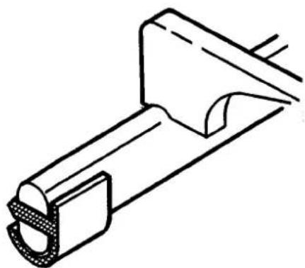
The pan support of this cooker is fitted with anti-scratch rubber feet.
These feet are dishwasher proof and should not be removed when cleaning the pan support.
If the rubber feet become detached from the pan support re-fit as per diagram.
Anti-scratch rubber feet can be obtained from your local Zanussi Service Force Centre.
The Burners
The burner caps and crowns can be removed for cleaning.
Wash the burners taps and crowns using hot soapy water, and remove marks with a mild paste cleaner. A well moistened soap impregnated steel wool pad can be used with caution, if the marks are particularly difficult to remove.
After cleaning, be sure to wipe dry with a soft cloth.

natural_image
Technical line drawing of a mechanical clamp or bracket component (no text or symbols)Cleaning the Oven

Before cleaning always allow the cooling fan to cool the oven down before switching off at the electricity supply.
The oven should be kept clean at all times. A build-up of fats or other foodstuffs could result in a fire, especially in the grill pan.
Cleaning materials
Before using any cleaning materials on your oven, check that they are suitable and that their use is recommended by the manufacturer.
Cleaners that contain bleach should NOT be used as they may dull the surface finishes. Harsh abrasives should also be avoided.
External cleaning
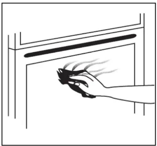
Regularly wipe over the control panel, oven door and door seal using a soft cloth well wrung out in warm water to which a little washing up liquid has been added.

To prevent damaging or weakening the door glass panels avoid the use of the following:
• Household detergent and bleaches
- Impregnated pads unsuitable for non-stick saucepans
- Brillo/Ajax pads or steel wool pads
• Chemical oven pads or aerosols
- Rust removers
- Bath/Sink stain removers
Clean the outer and inner door glass using warm soapy water. Should the inner door glass become heavily soiled it is recommended that a cleaning product such as Hob Brite, or Bar Keepers Friend is used.

DO NOT clean the oven door while the glass panels are warm. If this precaution is not observed the glass panel may shatter.
If the door glass panel becomes chipped or has deep scratches, the glass will be weakened and must be replaced to prevent the possibility of the panel shattering. Contact your local Service Centre who will be pleased to advise further.
natural_image
Illustration of a hand holding a spray gun near a window (no text or symbols)Oven Cavity
The enamelled oven cavity is best cleaned whilst the oven is still warm.
Wipe the oven over with a soft cloth soaked in warm soapy water after each use. From time to time it will be necessary to do a more thorough cleaning, using a proprietary oven cleaner.
If the soilage has become set, after the oven has cooled down, the following process will help to soften the splatters to help make cleaning easier.

^1 . Place the grill/ meat pan on the oven shelf positioned in the lowest runner.
-
Add a few drops of washing-up liquid to the pan and fill to about 12 mm. with boiling water from the kettle.
-
Close the oven door, turn the oven function knob on fan oven ⚙ and set the thermostat knob on 50°C.
-
After 15 minutes, turn off the thermostat and allow the fan oven to continue without heat for a further 5 minutes, when the temperature of the water will have cooled down.
-
Carefully remove the pan of water from the oven and use normal oven cleaners to clean away soil residues.
-
Leave a little of the soapy water to soak into any burned on spillage on the floor of the oven for a longer time if necessary.
Oven Shelves
To clean the oven shelves, soak in warm soapy water and remove stubborn marks with a well wetted soap impregnated pad. Rinse well and dry with a soft cloth.
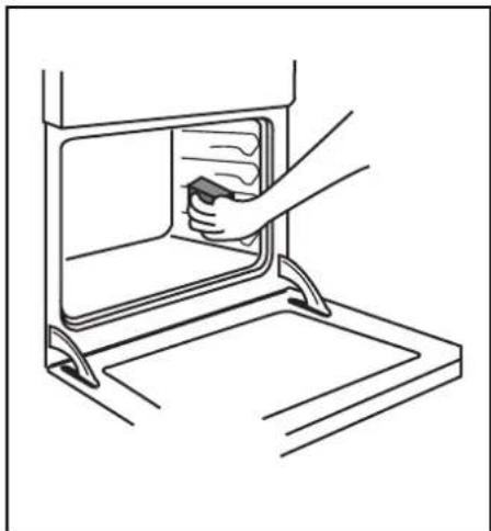
Oven lamp replacement
Disconnect the appliance.
Unscrew the lamp and substitute it with another suitable for higher temperature (300°C) having the following characteristics:
Tension: 230-240V (50Hz)
Power: 15W
Convection: E14
natural_image
Line drawing of a hand opening a kitchen appliance with a small container (no text or symbols)
Something Not Working
If the appliance is not working correctly, please carry out the following checks, before contacting your local Zanussi Service Centre.
IMPORTANT: If you call out an engineer to a fault listed below, or to repair a fault caused by incorrect use or installation, a charge will be made even if the appliance is under guarantee.
| SYMPTOM■ There is no spark when lighting the gas | SOLUTION◆ Check that the unit is plugged in and the electrical supply is switched on◆ Check that the RCCB has not tripped (if fitted)◆ Check the mains fuse has not blown◆ Check the burner cap and crown have been replaced correctly, e.g. after cleaning. |
| ■ The gas ring burns unevenly | ◆ Check the main jet is not blocked and the burner crown is clear of food particles.◆ Check the burner cap and crown have been replaced correctly, e.g. after cleaning. |
| ■ The oven does not come on | ◆ Check the oven is in manual operation and that both a cooking function and temperature have been selected.◆ Check the oven is wired in properly, and the socket switch or the switch from the mains supply to the oven are ON. |
| ■ The oven temperature light does not come on | ◆ Select a temperature with the thermostat control knob◆ Select a function with the oven function control knob. |
| ■ The oven light does not come on | ◆ Check the light bulb, and replace it if necessary (see "Replacing the Oven Light") |
| ■ It takes too long to finish the dishes, or they are cooked too fast. | ◆ The temperature may need adjusting |
| ■ Steam and condensation settle on the food and the oven cavity. | ◆ Refer to the contents of this booklet, especially to the chapter “Using the Oven”.◆ Leave dishes inside the oven no longer than 15-20 minutes after the cooking is completed. See page 10 |
| ■ The timer does not work | ◆ Check the instructions for the timer. |
| ■ The oven fan is noisy | ◆ Check the grease filter is correctly fitted.◆ Check that shelves and bakeware are not vibrating in contact with the oven back panel. |
Service and Spare Parts
SERVICE FORCE
If you require spare parts or an engineer contact your local Service Force Centre by telephoning:
08705 929929
Your call will be routed to your local Service Force Centre. For further details, please see the accompanying Customer Care Booklet.
CUSTOMER CARE
For general enquiries concerning your Zanussi appliance, contact our Customer Care Department by letter or telephone as follows:
Customer Care Department ZANUSSI
55-77 High Street Slough, Berkshire, SL1 1DZ Tel: 08705 - 727727
Peace of Mind for 12 Months
ZANUSSI GUARANTEE CONDITIONS
We, Zanussi, undertake that if, within 12 months of the date of the purchase, this Zanussi appliance or any part thereof is proved to be defective by any reason only of faulty workmanship or materials, we will, at our option, repair or replace the same FREE OF ANY CHARGE for labour, materials or carriage on condition that:
* The appliance has been correctly installed and used only on the gas and electricity supply stated on the rating plate.
* The appliance has been used for normal domestic purpose only, and in accordance with the manufacturer's instructions.
* The appliance has not been serviced, maintained, repaired, taken apart or tampered with by any person not authorised by us.
* All service work under this guarantee must be undertaken by a Zanussi Service Centre.
* Any appliance or defective part replaced shall become the Company's property.
* This guarantee is in addition to your statutory and other legal rights.
Home visits are made between 8.30am and 5.30pm Monday to Friday. Visits may be available outside these hours, in which case a premium will be charged.
Exclusions
This guarantee does not cover:
* Damage or calls resulting from transportation, improper use or neglect, the replacement of any light bulbs or removable parts of glass or plastic.
* Costs incurred for calls to put right an appliance which is improperly installed or calls to appliance outside European Community (EC) or European Free Trade Area.
* Appliances found to be in use within a commercial or similar environment, plus those which are the subject to rental agreements.
* Products of Zanussi manufacture which are not marketed by Zanussi.
European Guarantee
If you should move to another country within Europe then your guarantee moves with you to your new home subject to the following qualifications:
* The guarantee starts from the date you first purchased your product.
* The guarantee is for the same period and to the same extent for labour and parts as exist in the new country of use for this brand or range of products.
* This guarantee relates to you and cannot be transferred to another user.
* Your new home is within the European Community (EC) or European Free Trade Area.
* The product is installed and used in accordance with our instructions and is only used domestically, i.e. a normal household
* The product is installed taking into account regulations in your new country.
Before you move, please contact your nearest Customer Care centre, listed below, to give them details of your new home. They will then ensure that the local Service Organisation is aware of your move and able to look after you and your appliances.
France Senlis +33 (0)3 44 62 29 99
Germany Nürnberg +49 (0)911 323 2600
Italy Pordenone +39 (0)1678 47053
Sweden Stockholm +46 (0)8 738 79 50
UK Slough +44 (0)1753 219897
Instructions for the Installer
Technical Data
Model Number: ZCM 620 X
Appliance Class 2 sub class 1 and Class 1
APPLIANCE CATEGORY: II 2H3+
APPLIANCE GAS SUPPLY: Natural Gas G20 20 mbar
Dimensions
Height 900 mm
Depth 595 mm
Width 597 mm
Oven Capacity 1.8 Cu. ft
Hob
Rear left burner (semi-rapid) 2.0 kW
Front left burner (rapid) 3 kW
Rear right burner (semi-rapid) 2.0 kW
Front right burner (auxiliary) 1.0 kW
Oven
Top Heating Element 1.055 kW
Bottom Heating Element 1.250 kW
Convection Heating Element 2.080 kW
Grill Element 1.880 kW
Convection Fan 30 W
Oven light 15 W
Total rating 2.320 kW
Supply voltage (50 Hz) 230-240 V
| TYPE OF GAS | CHARACTERISTICS | BURNER | RAPID (large) | SEMI-RAPID (medium) | AUXILIARY (small) | |||
| POSITION | MAX | MIN | MAX | MIN | MAX | MIN | ||
| NATURAL GAS20 mbar | VALUE = 37.78 MJ/m ^3 Ws - 50.7 MJ/ m ^3 | NOMINAL THERMAL POWER kW | 3.0 | 0.65 | 2.0 | 0.45 | 1.0 | 0.33 |
| NOMINAL FLOW RATE m ^3 /h | 0.286 | 0.057 | 0.190 | 0.038 | 0.095 | 0.028 | ||
| NOZZLE REFERENCE 1/100 mm | 119 | Adjust. | 96 | Adjust. | 70 | Adjust. | ||
| LPG GAS28-30/37 mbar | VALUE = 49.92 MJ/Kg | NOMINAL THERMAL POWER kW | 2.8 | 0.65 | 2.0 | 0.45 | 1.0 | 0.33 |
| NOMINAL FLOW RATE g/h | 202 | 43.5 | 144 | 29 | 72 | 21,5 | ||
| NOZZLE REFERENCE 1/100 mm | 86 | 40 | 71 | 32 | 50 | 28 | ||
Important Safety Requirements
This appliance must be installed in accordance with the Gas Safety (Installation and Use) Regulations (current addition) and the I.E.E. Wiring Regulations. Detailed recommendations are contained in the following British Standard Codes of Practice - B.S. 6172, B.S. 5440: Part 2 and B.S. 6891: Current Editions.
Provision for Ventilation
The room containing the cooker should have an air supply in accordance with B.S. 5440: Part 2: Current Editions.
The following requirements for ventilation must be met.
The cooker should not be installed in a bed sitting room with a volume of less than 20m^3 , if it is installed in a room of volume less 5m^3 an air vent of effective area of 110cm^2 is required; if it is installed in a room of volume between 5m^3 and 10m^3 , an air vent of effective area 50cm^2 is required, while if the volume exceeds 11m^3 no air vent is required. However, if the room has a door which opens directly to the outside, no air vent is required even when the volume is between 5m^3 and 11m^3 .
If there are other fuel burning appliances in the same room, B.S. 5440: Part. 2: Current Editions should be consulted to determine the requisite air vent requirements.
Location
The cooker may be located in a kitchen, a kitchen/diner or bedsitting room but not in a bathroom or shower room.
For information regarding the fitting of flexible supply pipes, the highest temperature at the rear of this cooker which may come into contact with the supply pipe is 70^ C above ambient.
When the appliance has been installed there must be enough space for the glass hotplate lid to open fully.
Positioning the Cooker
Caution:
Some soft or badly fitted floor coverings can be damaged when the cooker is moved across their surface for cleaning. It is advisable to ensure that the floor covering in the area below the cooker is either securely fixed so as not to ruck up when the cooker is moved or, if preferred, removed.
Installation

Fig. 1
The appliance must be installed in accordance to the type X (standard EN 60335-2-6).
Therefore the appliance can not be installed beside furniture higher than the cooker worktop.
This cooker must only be installed by a CORGI registered installer.
1. Positioning the Appliance (Fig. 1)
Note A:
The appliance is designed to be flush fitted with 2mm clearance at each side to allow for it to be pulled forward for cleaning etc.
Note B:
The hotplate side trims should be flush with the cabinets and must not be below. Adjustable levelling feet at the front and rear are provided on the base of the appliance. Adjustment is obtained by rotating in or out, the feet at the front or rear of the appliance from the underside of the appliance, with the drawer removed.
A spirit level should be placed on a cake tray on one of the shelves to confirm that the appliance is correctly levelled.
The levelling feet fitted to the appliance will achieve a height to hotplate trims of 900mm-0 + 10.
Note C:
If the appliance is fitted next to a side wall or cabinets above height of the hotplate trims, then a gap of 115 mm is required.
Curtains must not be fitted immediately behind the cooker or within 115 mm of the sides of the cooker.
Note D:
Any wall cabinet or extractor must not be lower than 780mm above hotplate level.
Note E:
Wall cabinets may be fitted in line with the sides of the base units, providing that the lower edge of the wall cabinet is a minimum of 420mm above the worktop.

Fig. 2
Fitting the Stability Bracket (Not supplied)
If the cooker has to be installed with a flexible supply pipe, it is necessary that a stability device is fitted.
(See safety Requirements: Page 25).
If a stability bracket should be fitted by the installer, these instructions should be read in conjunction with the leaflet packed with the stability bracket.
Place cooker in its intended position and level cooker.
Mark off 295mm (11 ^1/2 ") from the right hand side of the cooker as shown, this is the centre line of the bracket fixing.
Draw a line 100mm (4") from the front edge of the levelling feet (see Fig. 2a) and remove cooker from its position. Mark off 480mm (19") back from this line on the centre line of the bracket to locate the front edge of the lower bracket.
Fix lower bracket (with two fixing holes) to the floor, then measure height from floor level to engagement edge on back of cooker, dimension 'A' of Fig. 2.
Assemble upper bracket to lower bracket so that underside of bracket is dimension 'A' +3mm (1/8") above floor level. Re-position cooker and check that top bracket engages into cooker back to a depth of 75mm (3"), as shown in Fig. 2.
Should the stability bracket currently installed not allow the cooker to stand correctly, ask the installer to replace it with the correct type.
Connecting to Gas
This cooker is designed to be installed with an appliance flexible connection. Connection is made to the RC 1/2 (1/2" B.S.P.) threaded entry pipe located just below the hotplate level on the rear right-hand side of the cooker. Check for gas soundness after connecting the gas supply.
The gas bayonet connector must be fitted in the shaded area indicated in the diagram. Take into account that it must be possible to pull the cooker forward sufficiently. The hose must not get caught on the stability bracket.
Note:
For certain types of gas bayonet connection used, it may not be possible for the appliance to be pushed fully back to the wall stops.
Important:
Flexible tubing MUST comply with BS.669 Current Edition.
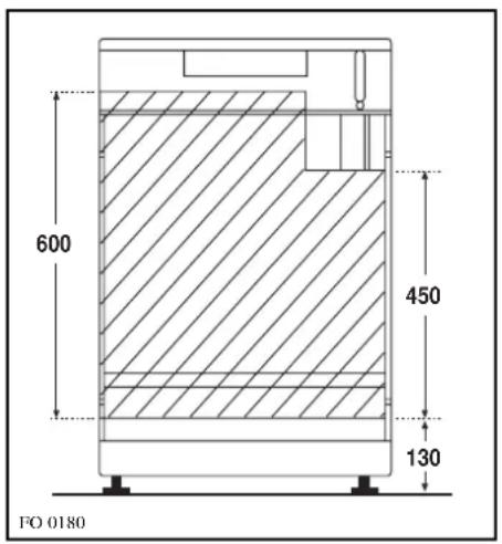
Fig. 3
Electrical connections

Any electrical work required to install this cooker should be carried out by a qualified electrician or competent person, in accordance with the current regulations.
THIS COOKER MUST BE EARTHED.
The manufacturer declines any liability should these safety measures not be observed.
This cooker is designed to be connected to a 230-240V 50Hz AC electrical supply.
Before switching on, make sure the electricity supply voltage is the same as that indicated on the cooker rating plate. The rating plate is located on the oven frame.
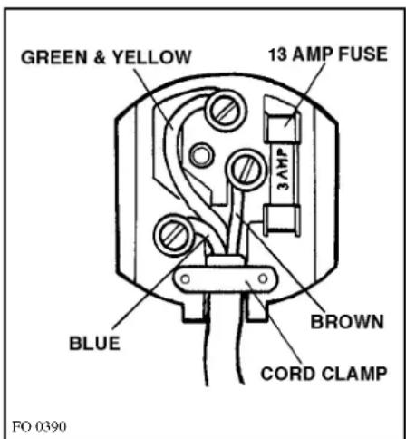
The cooker is supplied with a 3 core flexible supply cord incorporating a 13amp plug fitted. In the event of having to change the fuse, a 13amp ASTA approved (BS 1362) fuse must be used.
Should the plug need to be replaced for any reason, the wires in the mains lead are coloured in accordance with the following code:
Green and Yellow - Earth
Blue - Neutral
Brown - Live

Connect the green and yellow (earth) wire to the terminal in the plug which is marked with the letter 'E' or the earth symbol 12 or coloured green and yellow.
— Connect the blue (neutral) wire to the terminal in the plug which is marked with the letter 'N' or coloured black.
— Connect the brown (live) wire to the terminal in the plug which is marked with the letter 'L' or coloured red.
Upon completion there must be no cut, or stray strands of wire present and the cord clamp must be secure over the outer sheath.

A cut off plug inserted into a 13 amp socket is a serious safety (shock) hazard. Ensure that the cut off plug is disposed of safely.
Permanent Connection
In the case of a permanent connection, it is necessary that you install a double pole switch between the cooker and the electricity supply (mains), with a minimum gap of 3 mm. between the switch contacts and of a type suitable for the required load in compliance with the current electric regulations.
The switch must not break the yellow and green earth cable at any point.

Ensure that the cooker supply cord does not come into contact with surfaces with temperatures higher than 50 deg. C.
Commissioning
When the hob has been fully installed it will be necessary to check the minimum flame setting. To do this, follow the procedure below.
- Turn the gas tap to the MAX position and ignite.
- Set the gas tap to the MIN flame position then turn the control knob from MIN to MAX several times. If the flame is unstable or is extinguished follow the procedure below.
Procedure:

Re-ignite the burner and set to MIN. Remove the control knob.
The adjustment screw is located down the centre of the gas tap control shaft.
To adjust, use a thin bladed screwdriver and turn the adjustment screw until the flame is steady and does not extinguish, when the knob is turned from MIN to MAX. Repeat this procedure for all burners.
Pressure Testing

Remove left hand pan support and front left burner cap and crown.
Fit manometer tube over the injector.
Turn on the burner gas supply and ignite another burner supply.
The pressure reading should be nominally 20mbar and must be between 17 mbar and 25mbar.
Turn off the burner supplies.

a) Minimum adjustment screw b) Tap
Conversion from Natural to LPG Gas
It is important to note that this model is designed for use with natural gas but can be converted for use with butane or propane gas providing the correct injectors are fitted. The gas rate is adjusted to suit.
Method
- Ensure that the gas taps are in the 'OFF' position
- Isolate the hob from the electricity supply
- Remove all pan supports, burner caps, rings, crowns and control knobs.
- With the aid of a 7mm box spanner the burner injectors can then be unscrewed and replaced by the appropriate LPG Gas injectors (see table: page 24).
With the aid of a thin bladed screwdriver completely tighten down the by pass adjustment screw, which is located down the centre of the gas tap control shaft. Upon completion stick the replacement rating plate near the gas supply pipe.
IMPORTANT
The replacement/conversion of the gas hob should only be undertaken by a CORGI registered engineer.

- Installation
- Child Safety
- During Use
- Service
- Environmental Information
- Contents
- For the User
- Guide to Use the instructions
- For the Installer
- Oven Door Protection Device
- Description of the Cooker
- Fitting the Splash back
- Control Panel
- The Oven Cavity
- Accessories
- Operation
- WHEN THE COOKER IS FIRST INSTALLED
- Controls
- Hob burners
- Electric Oven
- Oven Function Control Knob
- Thermostat Control Knob
- hour Clock and Timer
- TO SET THE TIME OF DAY
- TO SET THE MINUTE MINDER
- MANUAL FUNCTION
- TO SET THE TIMER TO SWITCH OFF ONLY
- TO SET THE TIMER TO SWITCH THE OVEN ON AND OFF
- TO CANCEL A PROGRAMME
- Before the First Use of the Cooker
- Using the Oven
- i Hints and Tips
- Condensation and steam
- Cookware
- The effects of dishes on cooking results
- Storage Drawer
- Using the Conventional Oven
- How to Use the
- Conventional Oven
- THINGS TO NOTE
- Hints and Tips
- Cooking Chart
- Using the Fan Oven
- The advantages of cooking with this function are:
- √ Faster Preheating
- √ Lower Temperatures
- √ Even Heating for Baking
- How to Use the Fan Oven
- Roasting Chart
- Defrosting
- How to Use Defrosting
- How to Use the Grill
- Maintenance and Cleaning
- The Hob Top
- Pan Supports
- The Burners
- Cleaning the Oven
- Cleaning materials
- External cleaning
- Oven Cavity
- Oven Shelves
- Oven lamp replacement
- Something Not Working
- Service and Spare Parts
- SERVICE FORCE
- 929929
- CUSTOMER CARE
- Customer Care Department ZANUSSI
- Peace of Mind for 12 Months
- ZANUSSI GUARANTEE CONDITIONS
- Exclusions
- This guarantee does not cover:
- European Guarantee
- Instructions for the Installer
- Technical Data
- Dimensions
- Hob
- Oven
- Important Safety Requirements
- Provision for Ventilation
- Location
- Positioning the Cooker
- Caution:
- Positioning the Appliance (Fig. 1)
- Note A:
- Note B:
- Note C:
- Note D:
- Note E:
- Fitting the Stability Bracket (Not supplied)
- Connecting to Gas
- Note:
- Important:
- Electrical connections
- THIS COOKER MUST BE EARTHED.
- The manufacturer declines any liability should these safety measures not be observed.
- This cooker is designed to be connected to a 230-240V 50Hz AC electrical supply.
- Commissioning
- Procedure:
- Pressure Testing
- Conversion from Natural to LPG Gas
- Method
- IMPORTANT
Brand : ZANUSSI
Model : ZCM620X
Category : Kitchen