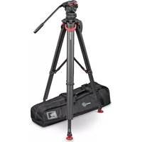
System FSB 10 FT MS - Tripod Sachtler - Free user manual and instructions
Find the device manual for free System FSB 10 FT MS Sachtler in PDF.


| Product Type | Professional Video Tripod with Fluid Head |
| Brand | Sachtler |
| Model | System FSB 10 FT MS |
| Head Type | Fluid Drag System with 3-step counterbalance |
| Payload Capacity | 10 kg (22 lbs) |
| Weight (Head & Tripod) | Approx. 5.5 kg (12.1 lbs) |
| Material | Carbon fiber legs, aluminum head |
| Leg Stages | 3-stage, with quick-release lever locks |
| Height Range | 33 cm (min) to 177 cm (max) |
| Bowl Diameter | 100 mm leveling bowl |
| Spreader | Mid-level spreader (MS) |
| Pan & Tilt Drag | Continuous, adjustable from 0 to max |
| Safety Lock | Tilt lock and pan lock with security mechanism |
| Mounting Plate | Quick-release sliding plate with 1/4" and 3/8" screws |
| Power | Not applicable (manual operation) |
| Maintenance | Clean with a soft cloth; avoid lubricants; check screws periodically |
| Storage | Store in a dry, dust-free environment; transport in provided case |
| Spare Parts | Available via authorized Sachtler service centers |
| Warranty | 2 years if registered online |
| Accessories Included | Tripod legs, fluid head, mid-level spreader, carry bag |
Frequently Asked Questions - System FSB 10 FT MS Sachtler
User questions about System FSB 10 FT MS Sachtler
0 question about this device. Answer the ones you know or ask your own.
Ask a new question about this device
Download the instructions for your Tripod in PDF format for free! Find your manual System FSB 10 FT MS - Sachtler and take your electronic device back in hand. On this page are published all the documents necessary for the use of your device. System FSB 10 FT MS by Sachtler.
USER MANUAL System FSB 10 FT MS Sachtler
natural_image
Black tripod with red clamps and black legs, no visible text or symbolsPart No. S2051-0001
S2052-0001
EN
www.sachtler.com
Copyright © 2018
All rights reserved.
Original Instructions: English
All rights reserved throughout the world. No part of this publication may be stored in a retrieval system, transmitted, copied or reproduced in any way, including, but not limited to, photocopy, photograph, magnetic or other record without the prior agreement and permission in writing of the Vitec Group Plc.
Disclaimer
The information contained in this publication is believed to be correct at the time of printing. Vitec Production Solutions reserves the right to make changes to the information or specifications without obligation to notify any person of such revision or changes. Changes will be incorporated in new versions of the publication.
We are making every effort to ensure that our publications are updated on a regular basis to reflect changes to product specifications and features. Should this publication not contain information on the core functionality of your product, please let us know. You may be able to access the latest revision of this publication from our website.
Vitec Production Solutions Ltd reserves the right to make changes to product design and functionality without notification.
Trademarks
All product trademarks and registered trademarks are the property of The Vitec Group Plc.
All other trademarks and registered trademarks are the property of their respective companies.
Published by:
Vitec Production Solutions
Supports Technical Publications Department
Email: technical.publications@vitecgroup.com


Other languages available DE. For download please visit www.sachtler.com/flowtech
Video tutorials are available, if required please contact support@vitecgroup.com for further details.
Contents
Safety....2
Warning symbols used in these instructions ..... 2
Health and Safety 2
Mounting and Installation 2
About this guide....3
Intended use .... 3
Warranty 3
Extended warranty 3
Operating Elements 4
Optional Accessories....5
Installation....6
Setting up the Tripod 6
Attach Optional Mid-Level Spreader ..... 7
Attach Optional Mid-Level Spreader flowtech 100 8
Operation of Mid-Level Spreader flowtech 100 . . . 8
Attach Optional Ground Spreader flowtech.....10
Operation of Ground Spreader 11
Using Locks When no Spreader Used ..... 14
No Spreader Mode 14
Spreader Mode 14
Opening Tripod Legs. 15
Alternative Locking Method....17
Close Tripod Legs 18
Accessories 18
Fit Supplied Attachment Mount ..... 18
Fit Optional Carry Strap....19
Attach Optional Rubber Feet. 19
Fit Carry Handle (S2051-1057)....20
Maintenance 20
Cleaning 20
Flush the Tripod....20
Hinge Lock Cleaning 21
Checking brake force 22
Adjusting brake force....22
Friction Adjustment 23
Specification 24
Safety
Important information on the safe installation and operation of the product. Read this information before operating the product. For your personal safety, read these instructions. Do not operate the product if you do not understand how to use it safely. Save these instructions for future reference.
Warning symbols used in these instructions
Safety cautions are used in these instructions. These safety instructions must be followed to avoid possible personal injury and possible damage to the product.

WARNING! Where there is a risk of personal injury or injury to others, comments appear supported by the warning triangle symbol.
Where there is a risk of damage to the product, associated equipment, process or surroundings, comments appear supported by the word 'CAUTION'.
Health and Safety

WARNING! Risk of personal injury or injury to others. All personnel must be fully trained and adhere to correct manual handling techniques and Health & Safety regulations. It is the responsibility of the local organisation to enforce safe working practices at all times.
Mounting and Installation

WARNING! Do not exceed the maximum payload capacity.

WARNING! Tripod spike feet can be dangerous, take care when handling. Always place tripod on the ground before releasing quick release levers.

WARNING! Risk of finger entrapment. Avoid trapping fingers when operating the tripod.

WARNING! Trip hazard. Set the tripod footprint to suit the shooting environment.

WARNING! Toppling hazard. Do not leave unattended. Keep out of reach of children.

WARNING! When in use always fully lock the tripod quick release levers to prevent the tripod collapsing.

WARNING! When releasing the quick release levers, be prepared to support the weight of any attached payload. The levers are only sufficiently locked when in the fully closed (down) position.

CAUTION! Always hold the payload securely when making adjustments to the tripod height or footprint.

CAUTION! Do not place your foot or heavy weight onto the spreader.

CAUTION! Always remove the camera before transporting.
About This Guide
About this guide
This user guide is an important part of the product and is aimed at the personnel who operate and maintain the tripod. It contains information about the tripod and its proper use and serves to safeguard users and their equipment.
Intended use
This tripod has been designed for professional use in television studios and outside locations for supporting fluid heads and cameras. Any use above and beyond this purpose is deemed improper and will void the warranty.
Warranty
The product is covered by a one year warranty.
The warranty will be invalidated if:
- The tripod is improperly installed or used in a manner contrary to this user guide.
- The tripod housing is opened by unauthorised personnel.
We reserve the right to make changes to the product based on technological advances.
Extended warranty
Please register at www.sachtler.com for an extended warranty period.
Operating Elements
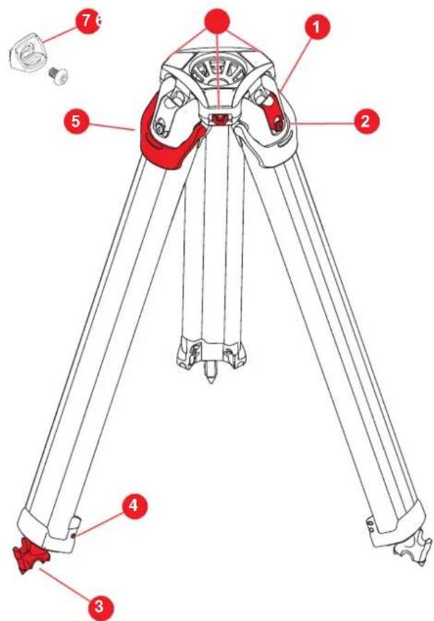
| Pos No. | Description |
| 1 | Hinge Lock Slider |
| 2 | Hinge Lock Button |
| 3 | Double-spiked Foot |
| 4 | Leg Magnetic Clasp |
| 5 | Quick Release Lever |
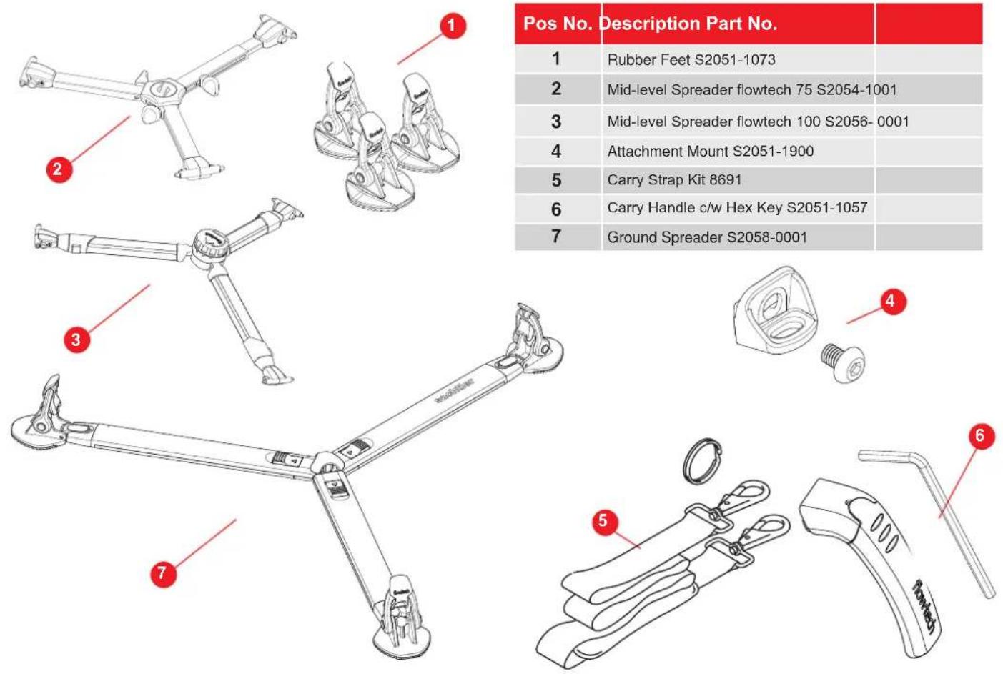
| 6 | Accessory Dock x 3 |
| 7 | Attachment Mount |
Optional Accessories
Installation
Setting up the Tripod
- The legs are secured using magnetic catches. Pull the legs from the bottom to separate. Note! If preferred this step may be performed after step 3.
- Place the tripod on the ground. Lift the quick release levers fully and raise the tripod to the required height.

WARNING! Tripod spiked feet can be dangerous. Always place tripod on the ground before releasing quick release levers.
- With the correct height achieved, lower the quick release levers to lock the legs in position.

WARNING! The legs are only sufficiently locked when the locking levers are in the fully closed (down) position.
1


Installation
Attach Optional Mid-Level Spreader flowtech 75

CAUTION! Ensure the latching pins are fully engaged with the locating holes in the tripod. Failure to attach correctly could result in damage to the equipment

The tripod is delivered with the Hinge Lock in the OFF position for use with a spreader. (See page 10 for lock operation).
- Hold the spreader between thumb and forefinger and squeeze the release buttons on each side.

-
Align the latching pins with the locating holes on the tripod leg.
-
Release the buttons to lock the spreader in place.

- Unlock the spreader arms to allow the arms to extend as required.
- Tighten the spreader locks when the tripod legs are in the correct position.


If the spreader will not lay flat when fitted, check the Hinge Lock is in the OFF (spreader mode) position for use with a spreader. (See page 10 for lock operation).
Installation
Attach Optional Mid-Level Spreader flowtech 100

CAUTION! Ensure the latching pins are fully engaged with the locating holes in the tripod. Failure to attach correctly could result in damage to the equipment

The tripod is delivered with the Hinge Lock in the OFF position for use with a spreader. (See page 10 for lock operation).
- Hold the spreader between thumb and forefinger and squeeze the release buttons on each side.

- Align the latching pins with the locating holes on the tripod leg.
- Release the buttons to lock the spreader in place.

Operation of Mid-Level Spreader flowtech 100
- Press and hold the arm release button (as below).
- Extend the inner arm to the required length and release the button.
Visual Distance Markers

natural_image
Technical illustration of a mechanical device with red components and a magnified inset showing a red rod assembly (no text or symbols)
NOTE! The inner arm should not be pushed back against the ratchet mechanism, always hold the release button down whilst extending or retracting the inner arm.
The inner section has three distance markers (as shown above), this helps to visually set the length of the spreader arms.

If the spreader will not go into the selected position, check the Hinge Lock is in the OFF (spreader mode) position for use with a spreader. (See page 10 for lock operation).
Installation
The spreader has 4 x locking positions 50, 40, 30 and 0°
- Rotate the adjustment cap on top of the spreader, anticlockwise to allow the spreader to open to the selected setting.
- A positive click will be felt as each position is achieved.

Installation
Attach Optional Ground Spreader flowtech 75 / 100

CAUTION! Ensure the ground spreader legs are all the same length before attempting to fold the tripod with the spreader attached. Failure to observe this procedure could lead to damage of the Ground Spreader

The tripod is delivered with the Hinge Lock in the OFF position for use with a spreader. (See page 14 for lock operation).
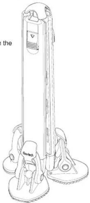
Ground Spreader shown in the stored position
natural_image
Line drawing of a vertical stand with base and legs, no text or symbols present- Place the spreader flat on the floor.

natural_image
Technical line drawing of a three-legged robotic arm with mounting feet (no text or symbols)- Place the tripod foot on the ball of the spreader foot.

natural_image
Illustration of a robotic arm gripping a red object, with no visible text or symbolsInstallation
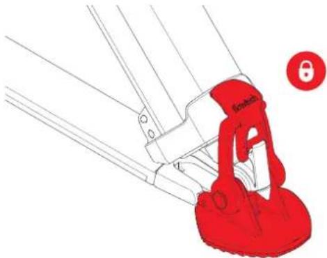
- Bend the rubber strap 1 and engage the bottom edge of the lever in the tripod recess.
- Lift the lever 2 upwards towards the tripod until it locks in place. Repeat for all three legs.

- Tripod spiked foot secured in the Ground Spreader Foot.
natural_image
Illustration of a red 3D-printed object with a circular badge labeled '8' (no text or symbols on the object itself)Operation of Ground Spreader
- When assembled on the tripod, use your foot to press and hold the arm release button (as below).
- Extend the inner arm to the required length and release the button. (There are a total of 12 positions).

NOTE! The inner arm should not be forced back against the mechanism, always hold the release button down whilst extending or retracting the inner arm.
The inner section has distance markers (as shown below), this helps to visually set the length of the spreader arms.


If the spreader will not go into the desired position, check the tripod Hinge Lock is in the OFF (spreader mode) position for use with a spreader. (See page 14 for lock operation).
Installation
Closing Tripod with Ground Spreader Attached
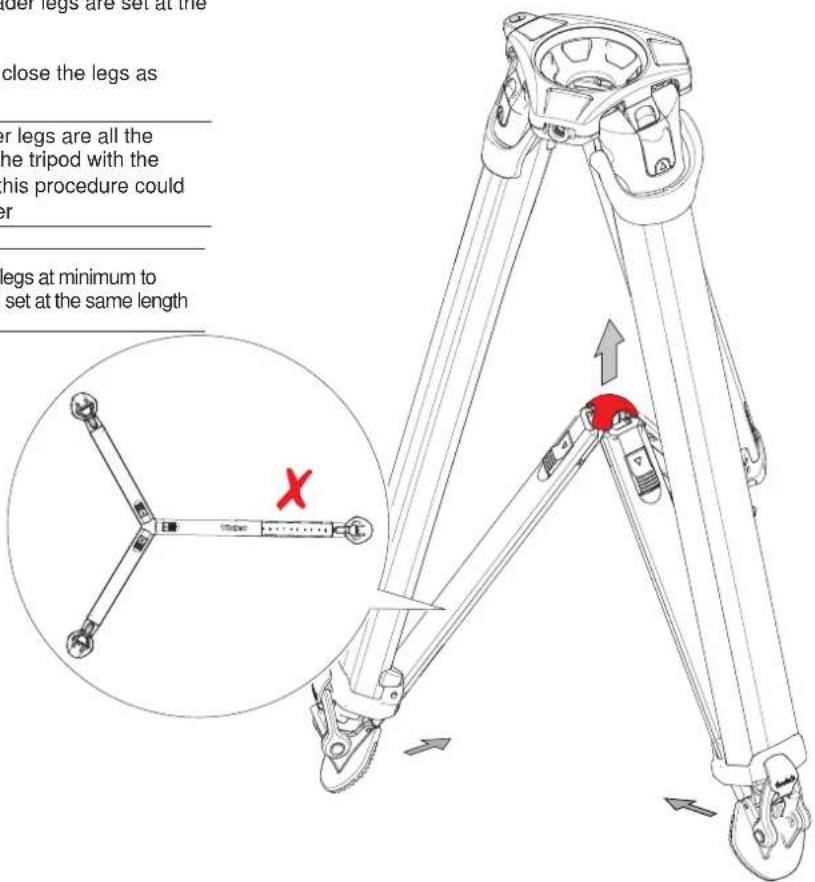
- To close the tripod legs, ensure all the spreader legs are set at the same distance.
- Lift the spreader using the centre knob, then close the legs as normal.

CAUTION! Ensure the ground spreader legs are all the same length before attempting to fold the tripod with the spreader attached. Failure to observe this procedure could lead to damage of the Ground Spreader

The tripod can be closed with the spreader legs at minimum to maximum extension, as long as they are all set at the same length
Installation
Remove Foot from Spreader
- To remove the feet from the spreader, push the foot release button towards the centre of the spreader.
- Lift the foot from the spreader.
- Reverse the procedure to re-attach the feet to the spreader


The spreader can be removed from the feet while they are still attached to the tripod
Cleaning.
After each use, brush off any dirt or debris, if necessary wash down with clean water.
Installation
Using Locks When no Spreader Used

The tripod can be used without a spreader using the three lock positions.
- The tripod has 3 x lock positions 20°, 46° and 72°.


Caution! Risk of damage. Only use the 72° hinge lock setting with the legs in the fully retracted position. Do not apply excessive load. Do not place load on the leg profiles.

Caution! Risk of damage. In No Spreader Mode (Hinge Lock ON) position, ensure that the feet are free to adapt to a new footprint area when raising or lowering the tripod.
No Spreader Mode
- With the lock in the raised position the lock is ON.
Hinge Lock Slider in the engaged (ON) position. (Leg will stop at pre-set positions)

natural_image
Illustration of a hand pressing a red liquid into a container with a small circular icon labeled '8' (no text or symbols on the diagram itself)Spreader Mode
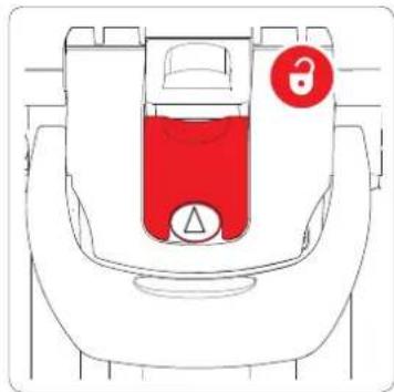
- With the lock in the lower position the lock is OFF.
Hinge Lock Slider in the neutral (OFF) position. (Legs free to move through full movement)
natural_image
Diagram of a car interior with a red liquid container and a warning symbol (no text or labels)
Caution! Risk of damage. When using with a spreader or dolly, ensure the Hinge Lock Slider is in the OFF position.
Installation
Opening Tripod Legs
The first position at 20irc is likely to be the most used position.
- Press the lock button to engage the lock. (No Spreader Mode)
- Pull the leg outward and it will stop at the 20irc lock position.

Repeat for the remaining legs.

The angle of each leg can be adjusted independently of the other two legs.
- To select the 46irc or 72irc position, disengage the lock.
a. As a safeguard against accidental collapse the leg must be moved inwards slightly ① to relieve the tension on the lock.
b. Push the lock slider down ② and pull the leg outwards ③.

Installation
- Move the leg past the 20irc position.
- Engage the Lock Slider by pushing the Hinge Lock Button.

- Continue pulling the leg until it stops at the 46° lock position.

- Repeat procedure for the 72° position.

- Repeat for the remaining legs as required.
Installation
Alternative Locking Method
- An alternative method would be to release the Hinge Lock, and fully open the leg to 90°

- Engage the lock.


WARNING! Risk of finger entrapment. Avoid trapping fingers when operating the tripod.
- Move the leg towards the body. As the leg passes each lock point, an audible click will be heard, the leg is prevented from opening past this point again without disengaging the lock first.

Installation Accessories
Close Tripod Legs
- The legs may be closed with or without the Lock being engaged.
- Ensure the tripod legs are fully collapsed before moving them inward.

WARNING! Risk of finger entrapment. Avoid trapping fingers when closing the tripod.

The tripod is designed to accommodate the Mid-Level Spreader when collapsed.
- Ensure the magnetic clasps have engaged and the legs are securely held.

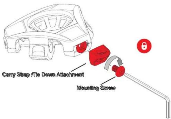
Fit Supplied Attachment Mount
- There are three accessory docks. These can be used to dock the supplied attachment mount, optional handle or a Magic Arm etc..
- Offer the accessory to the docking point on the tripod head.
- Insert the screw and tighten clockwise using a 5.5mm Hex key, tighten firmly.
- Follow the same procedure to attach h optional accessories to the remaining mounting points if required.
Accessories
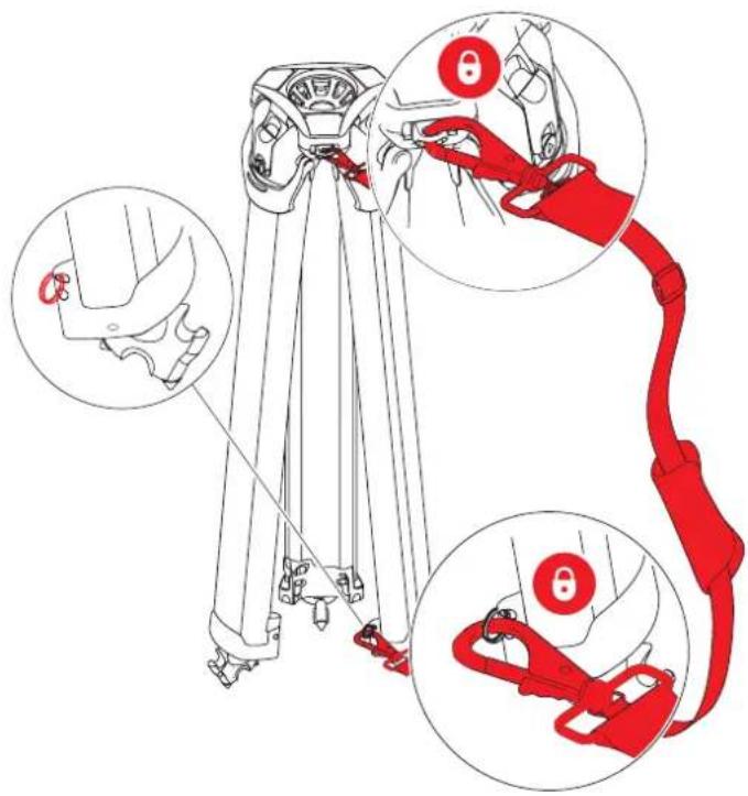
Fit Optional Carry Strap
- Fit the attachment mount as previous section: "Fit Supplied Attachment Mount".
- Fit the split ring to the mounting point at the bottom of the upper section.
- Attach the strap clasps to the mounting points.
Attach Optional Rubber Feet
- Place the rubber foot between the spikes. Check the marking on the foot for the correct orientation. The 'flowtech' marking must face outwards.
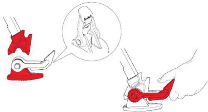
- Bend the rubber strap 1 and engage the bottom edge of the lever in the tripod recess.
- Lift the lever ② upwards towards the tripod until it locks in place.
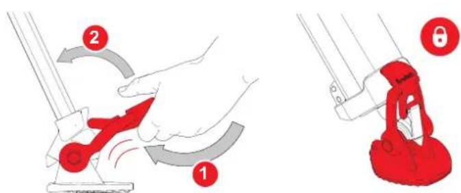
Accessories
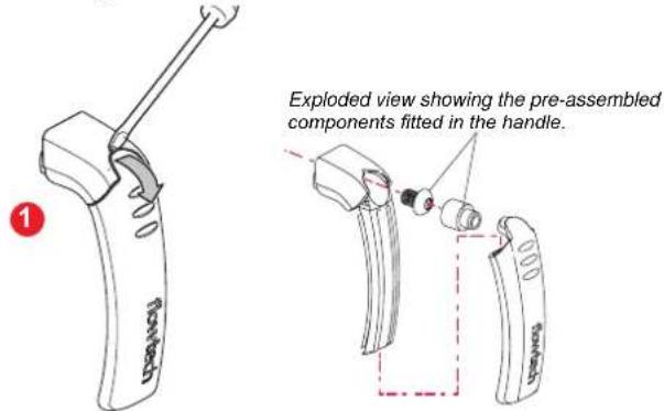
Fit Optional Carry Handle (S2051-1057)
To attach the handle to one of the accessory docks.
- Using a fingernail or small screwdriver, lever the rubber sleeve away from the top of the handle to reveal the (pre installed) mounting screw and spacer.
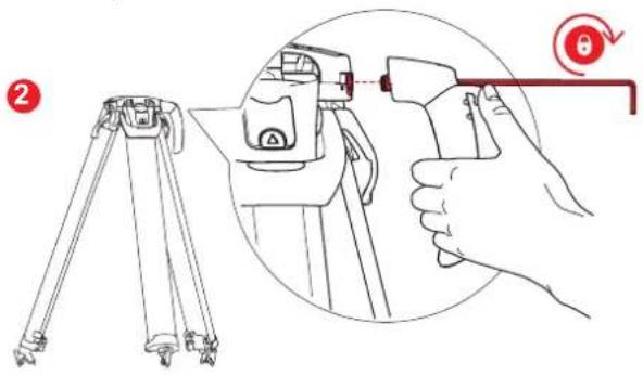
- Insert the supplied Hex key through the spacer, into the hex bolt in the handle, align with the accessory dock and tighten clockwise, ensure the handle is secure.
Maintenance
Cleaning


Video tutorials are available, if required please contact support@vitecgroup.com for further details.

CAUTION! Do not use solvent or oil based cleaners, abrasives or wire brushes to remove accumulations of dirt as these will damage the protective surfaces. Use clean water only.
During normal use the only cleaning required is a periodic wipe-down with a lint-free cloth. Any dirt that accumulates during storage or periods of non-use may be removed with a vacuum cleaner. Particular attention should be paid to the ball base of the tripod.
Use out-of-doors under adverse conditions will require special attention. Salt spray should be washed off with fresh water at the earliest opportunity. Sand and dirt acts as an abrasive and should be removed using a semi-stiff brush or vacuum cleaner.
If exposed to extreme conditions, sand or grit could enter the tripod. This will require flushing to remove any contaminants.
Flush the Tripod
- Place the tripod in a bucket of clean, 30 cm deep water.
- Release the quick release levers and extend tripod fully.
- Keeping the feet in the water, collapse and extend the tripod repeatedly, forcing water through the leg sections until the leg moves freely with no sign of sticking or contamination.
- If required turn the tripod upside down and repeat.
- Wipe down the outer surface with a clean dry cloth.
Maintenance
Hinge Lock Cleaning
The Hinge lock is designed so that sand or other debris may be worked out of the hinge lock mechanism.
Repeatedly operate the button and hinge slider, combined with blowing out the debris until the mechanism operates smoothly.
Should this procedure fail to sufficiently clear the debris, follow the instructions below to disassemble the mechanism for cleaning.
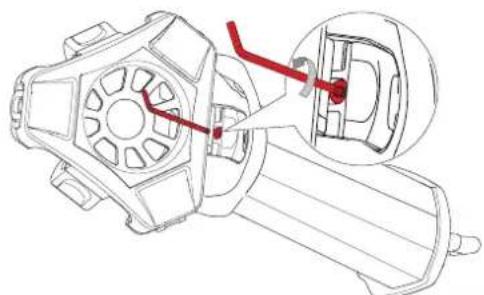
- Pull the leg out to gain access to the M4 lock screw.
- Using a 2.5mm or 332 " ball ended hex key, remove the M4 lock screw by turning anticlockwise.
natural_image
Technical line drawing of a mechanical component with a red tool inserted, showing internal parts and a close-up view (no text or symbols)
Caution! If the screw is dropped in the lock mechanism, do not try to close the leg. Turn the tripod upside down and shake the screw out or retrieve using pliers.
- With the screw removed raise the leg to the horizontal position and push the hinge slider towards the bowl and lift out.

natural_image
Technical line drawing of two car head profiles with red adjustment arrows indicating movement (no text or symbols)- Lift out the hinge lock button.

natural_image
Line drawing of a car interior compartment with a red connector (no text or symbols)- Use compressed air and a soft brush to remove any debris.

WARNING! When using compressed air, wear suitable safety glasses to avoid injury.
- Work the hinge lock up and down using the flat edge of a screw driver pushing on the centre of the lock, debris will work its way out the bottom of the mechanism.

natural_image
Mechanical assembly diagram showing a disassembly of a component into a housing, with a magnified inset highlighting the internal structure (no text or symbols present)- Once the lock is clean assembly is a reversal of steps 2 - 4.

Caution! When replacing the M4 lock screw, offer it to the thread and turn anticlockwise until you hear a click then tighten clockwise. This will prevent the screw from being cross threaded.
Maintenance
Checking brake force
Periodically check the effectiveness of the leg brake force and adjust if necessary.
- Extend the middle and lower sections to 20 cm each.
- Place a rubber mat or similar on a set of scales to prevent damage and skidding. Stand one leg on a set of scales and apply a vertical downward force.

WARNING! Use a non-slip mat to ensure the foot does not slip from the scales when applying downward pressure.
WARNING! Finger entrapment. Take care not to trap fingers.
flowtech 75 flowtech 100
| X | < 20 kg(44 lb) | < 30 kg(66 lb) |
| √ | 20 - 30 kg(44 - 66 lb) | 30 - 40 kg(66 - 88 lb) |
| X | >30 kg(66 lb) | >40 kg(66 lb) |
- With an average downward force of 20 - 30 kg (44 - 66 lb) flowtech 75 or 30 - 40 kg (66 - 88 lb) flowtech 100 applied, the leg should remain extended.
- If the leg starts to collapse before a 20 kg (44 lb) flowtech 75 or 30 kg (66 lb) flowtech 100 force is achieved then adjustment is required. "See Adjusting brake force".


Average slip force
Adjusting brake force
- Lift the quick release lever to clear the adjustment screw. Using a 2.5mm or 332 hex key, turn clockwise to increase the brake force.
- 10 full turns = 2 kg (4.4 lb) of additional brake force.

CAUTION! Do not adjust more than required as this will lead to increased wear and stress on the brake components.

- When the adjustment is made, test the brake force again on the scales, repeat if necessary.
- Repeat the procedure for the remaining two legs.

Should the adjustment range become insufficient to achieve the correct brake force, please contact your local service centre. www.sachtler.com
Maintenance
Leg Friction Adjustment
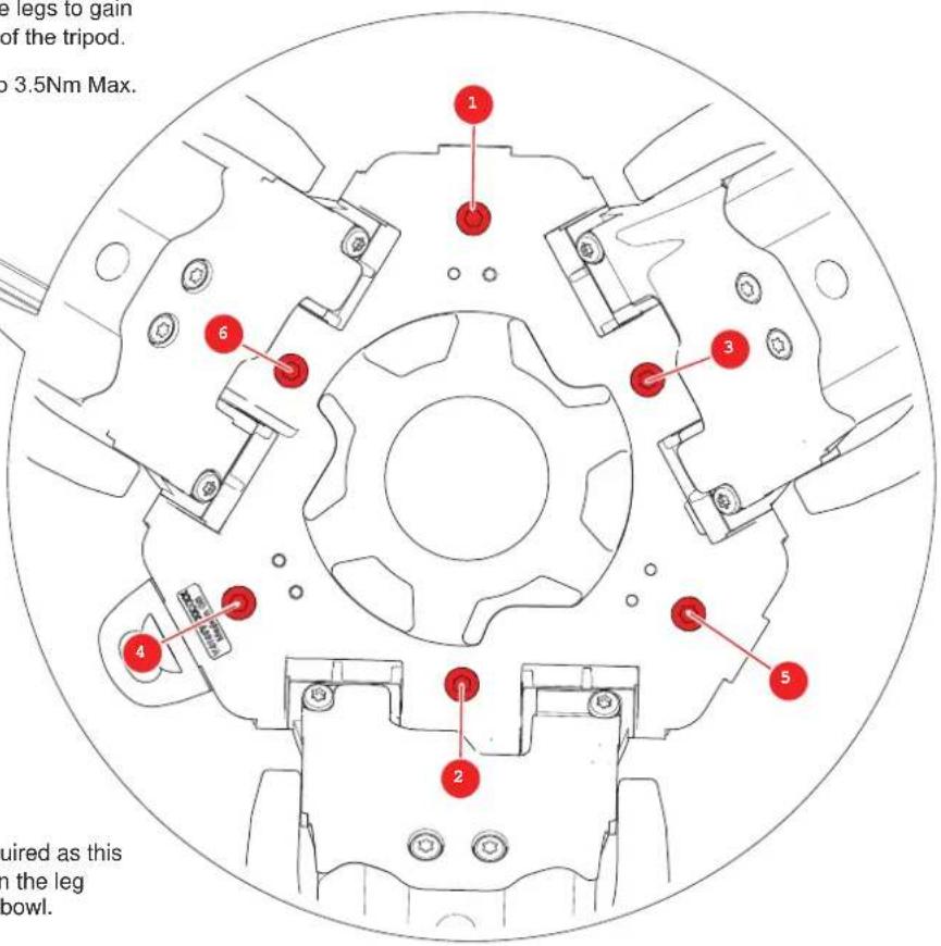
- Should the leg friction require adjustment, open the legs to gain access to the M5 friction screws on the underside of the tripod.
- The correct torque for these M5 screws is 2.5Nm to 3.5Nm Max.

natural_image
Technical line drawing of a tripod-mounted mechanical component (no text or symbols)- Use a torque screwdriver to adjust the M5 screws to the correct torque. (2.5Nm to 3.5Nm Max)
- Always tighten the screws in an opposite pattern following the numbered pattern in the diagram.
- If a torque screwdriver is not available, use a Hex Key; follow the pattern in the diagram, but only tighten the screws by a small amount taking care not to over-tighten.
- Test the legs for correct friction and adjust again if necessary.

CAUTION! Do not adjust more than required as this will lead to increased wear and stress on the leg friction components and damage to the bowl.
Technical Specification
| 75 mm Tripod | 100 mm Tripod | 75 mm Tripod | 100 mm Tripod | |||
| Bowl 75 mm 100mm |  | Maximum Operational HeightOn Mid-Level Spreader | 157 cm(61.81 in.) | 155 cm(61.00 in.) | ||
| Maximum payload | 20 kg(44 lb) | 30 kg(66 lb) |  | Minimum Operational HeightOn Mid-Level Spreader | 63 cm(24.8 in.) | 52 cm(20.5 in.) |
| WeightTripod Only | 2.9 kg(6.39 lbs) | 3.2 kg(7.01 lbs) |  | Maximum Operational HeightOn Ground Spreader | 158 cm(62 in) | 159 cm(63 in) |
| Transport Length | 68 cm(26.7 in.)Excluding rubber foot. | 68 cm(26.7 in.)Excluding rubber foot. |  | Minimum Operational HeightOn Ground Spreader | 41 cm(16.4 in) | 43 cm(16.9 in) |
| Operational Temperature | -40°C to 60°C(-40°F to 140°F) | -40°C to 60°C(-40°F to 140°F) |  | When used without rubber feet the tripod height will decrease by up to 1.8 cm. | ||
| Maximum Operational Height(On Hinge Lock) | 153 cm(60.23 in.) | 153 cm(60.23 in.) |  | Material | Carbon Fibre | Carbon Fibre |
| Minimum Operational Height(On Hinge Lock) | 26 cm(10.23 in.) | 26 cm(10.23 in.) |  | Extensions X2 X2 |
Technical specifications are subject to change without notice.
Publication No. S2051-4983/3


Sachtler
A Vitec Group Brand
www.sachtler.com
- Copyright © 2018
- Disclaimer
- Trademarks
- Published by:
- Contents
- Safety....2
- Operating Elements 4
- Optional Accessories....5
- Installation....6
- Accessories 18
- Maintenance 20
- Specification 24
- Safety
- Warning symbols used in these instructions
- Health and Safety
- Mounting and Installation
- About This Guide
- Intended use
- Warranty
- Extended warranty
- Operating Elements
- Optional Accessories
- Installation
- Setting up the Tripod
- Attach Optional Mid-Level Spreader flowtech 75
- Attach Optional Mid-Level Spreader flowtech 100
- Operation of Mid-Level Spreader flowtech 100
- Attach Optional Ground Spreader flowtech 75 / 100
- Operation of Ground Spreader
- Closing Tripod with Ground Spreader Attached
- Remove Foot from Spreader
- Cleaning.
- Using Locks When no Spreader Used
- No Spreader Mode
- Spreader Mode
- Opening Tripod Legs
- Alternative Locking Method
- Installation Accessories
- Close Tripod Legs
- Fit Supplied Attachment Mount
- Accessories
- Fit Optional Carry Strap
- Attach Optional Rubber Feet
- Fit Optional Carry Handle (S2051-1057)
- Maintenance
- Cleaning
- Flush the Tripod
- Hinge Lock Cleaning
- Checking brake force
- Adjusting brake force
- Leg Friction Adjustment
Brand : Sachtler
Model : System FSB 10 FT MS
Category : Tripod