
U80 - Marine Electronics SIMRAD - Free user manual and instructions
Find the device manual for free U80 SIMRAD in PDF.


| Product Type | Marine autopilot remote control (NF80, FU80, QS80 models) |
| Brand | Simrad |
| Model | U80 (covers NF80, FU80, QS80) |
| Dimensions (H x W x D) | 63 mm x 51 mm x 16 mm (2.46" x 1.98" x 0.63") |
| Weight | NF80/FU80: 0.5 kg (1.10 lbs); QS80: 0.4 kg (0.88 lbs) |
| Display | 2" monochrome, transflective, 128 x 64 pixels |
| Power Supply | Via CAN bus or SimNet backbone (6 m Micro-C drop cable included) |
| Power Consumption | Off: <20 mA (LEN 1); On with max illumination: <110 mA (LEN 3) |
| Operating Temperature | -25°C to +55°C (-13°F to +131°F) |
| Compass Safe Distance | 0.4 m (ref. IEC 60945 sec.11.2) |
| Environmental Protection | IEC 60945 sec. 8.8 exposed, front when desk mounted or bulkhead mounted with optional frame; corresponds to IP X6 |
| Compatible Autopilot Systems | AP70, AP80, AP24, AP28, NSE, NSS, NSO (Simrad multifunction displays) |
| Control Modes (per model) | NF80: NFU, AUTO, NoDrift; FU80: FU, AUTO, NoDrift; QS80: NFU, AUTO, NoDrift, NAV, Wind |
| Key Functions | CMD (take command/activate thrusters), LIGHT (adjust illumination/dim), STBY (standby), MODE (mode toggle) |
| Mounting Options | Panel mount (flush) with gasket and screws; optional bulkhead mounting frame |
| Cable Length | Micro-C drop cable, 6 m (19.7 ft) factory connected |
| Maintenance | Clean with fresh water and mild soap; avoid chemical cleaners and hydrocarbons |
| Warranty | Separate warranty card; refer to brand website |
| Spare Parts / Accessories | Optional bulkhead frame; replacement lever for FU80; gasket and screws included |
| Regulatory Compliance | CE (2004-108 EC EMC Directive), C-Tick, Wheelmark approved (European Marine Equipment Directive 96/98) |
Frequently Asked Questions - U80 SIMRAD
User questions about U80 SIMRAD
0 question about this device. Answer the ones you know or ask your own.
Ask a new question about this device
Download the instructions for your Marine Electronics in PDF format for free! Find your manual U80 - SIMRAD and take your electronic device back in hand. On this page are published all the documents necessary for the use of your device. U80 by SIMRAD.
USER MANUAL U80 SIMRAD
natural_image
Three black SIMRAD remote control devices with digital displays and control knobs (no visible text or symbols on the devices themselves)Preface
As Navico is continuously improving this product, we retain the right to make changes to the product at any time which may not be reflected in this version of the manual. Please contact your nearest distributor if you require any further assistance.
It is the owner's sole responsibility to install and use the equipment in a manner that will not cause accidents, personal injury or property damage. The user of this product is solely responsible for observing safe boating practices.
NAVICO HOLDING AS AND ITS SUBSIDIARIES, BRANCHES AND AFFILIATES DISCLAIM ALL LIABILITY FOR ANY USE OF THIS PRODUCT IN A WAY THAT MAY CAUSE ACCIDENTS, DAMAGE OR THAT MAY VIOLATE THE LAW.
Governing Language: This statement, any instruction manuals, user guides and other information relating to the product (Documentation) may be translated to, or has been translated from, another language (Translation). In the event of any conflict between any Translation of the Documentation, the English language version of the Documentation will be the official version of the Documentation.
This manual represents the product as at the time of printing. Navico Holding AS and its subsidiaries, branches and affiliates reserve the right to make changes to specifications without notice.
Copyright
Copyright © 2011 Navico Holding AS.
Warranty
The warranty card is supplied as a separate document.
In case of any queries, refer to the brand web site of your display or system:
pro.simrad-yachting.com
www.simrad-yachting.com
2 Introduction
2 About this manual
2 Wheelmark approval
3 Parts included
4 Installation
4 Mounting
6 Wiring
7 Operation
7 Basic operation - all remotes
10 Using the NF80
12 Using the FU80
14 Using the QS80
16 Changing commanded rudder direction
16 Alarms
17 Restoring factory settings
17 Maintenance
18 Changing default settings
18 The main menu
19 Specifications
19 Technical specifications
20 Drawings
1
Introduction
About this manual
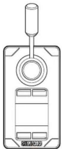
This manual describes how to install and use the FU80, NF80 and the QS80 remotes.
natural_image
Line drawing of a device with a cylindrical top and rectangular base, no text or symbols present
natural_image
Front view of a SIMR20 device casing with a circular button and rectangular panel (no text or symbols)
natural_image
Front view of a SIM R2D device casing with control panel and circular button (no text or symbols)NF80FU80QS80
These remotes can be used to remotely control the AP70, AP80, AP24 and AP28 autopilot systems. They can also be used to remotely operate the autopilot function in NSE, NSS and NSO (Simrad Multifunction Displays).
For detailed description of operational modes, see the Operator manual for you autopilot system or for your NSE/NSO/NSS.
For details about installation of CAN bus or SimNet backbone, see the autopilot System Installation manual.

Wheelmark approval
The remotes are produced and tested in accordance with the European Marine Equipment Directive 96/98 and can be used in a Wheelmark installation according to the certificates.
For details and certificates refer to our websites:
pro.simrad-yachting.com and www.simrad-yachting.com.
Parts included
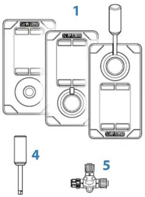
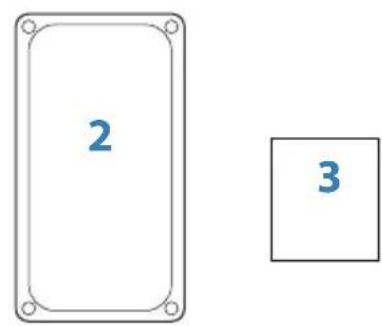

Key Description
| 1 Remote unit, including 6 m (19.7 ft) Micro-C drop cable |
| 2 Gasket for panel sealing |
| 3 Screws and accessories |
| 4 Long type lever (FU80 and NF80) |
| 5 Micro-CT-connector |
| 6 User manual |
| 7 Mounting template |
| 8 Warranty card |
2
Installation
Mounting
The remotes should be mounted with special regard to the units' environmental protection, temperature range and cable length. Refer "Technical specifications" on page 19.
→ Note: If installed outdoors, select a position and a mounting option that prevents water from remaining on the display. It is recommended to cover the units when not in use.
Panel mount
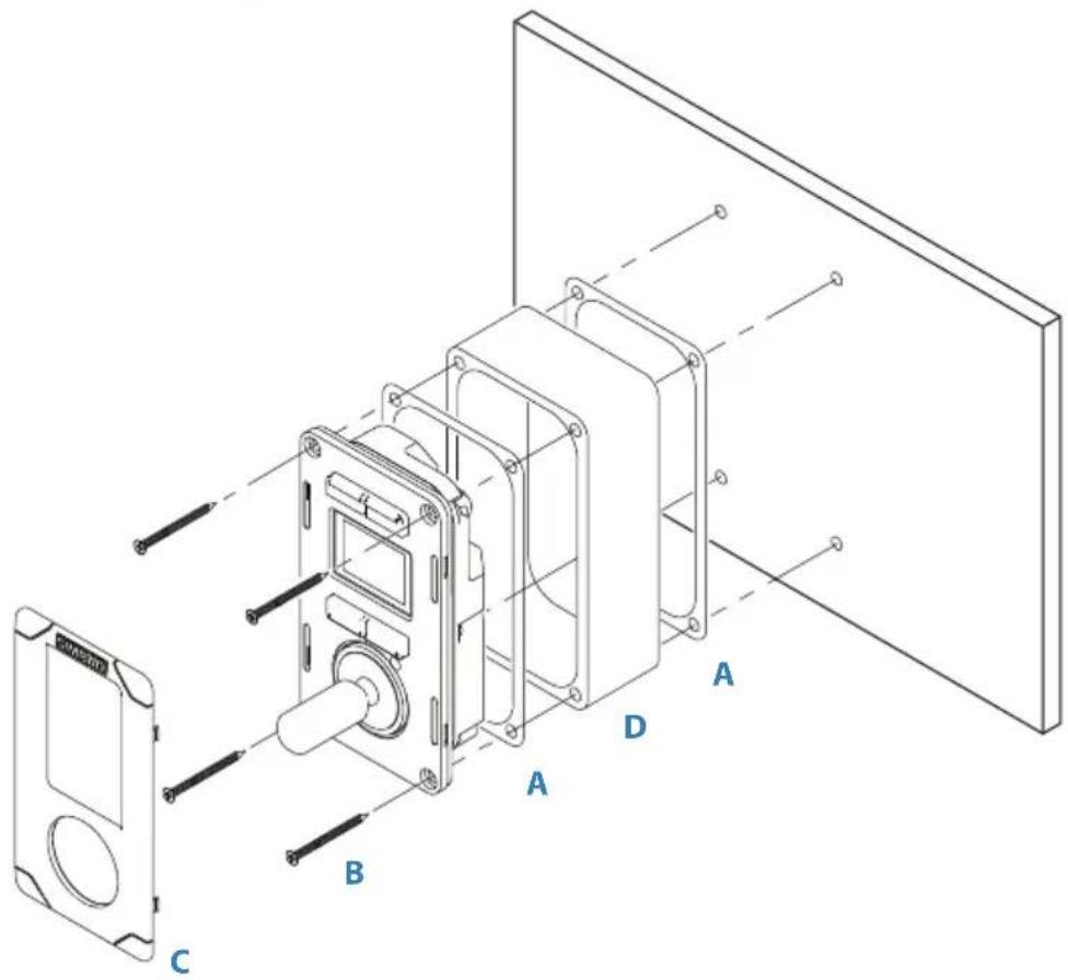
- Attach the mounting template to the selected position
- Drill fastening holes and remove the cut-out
- Peel backing off the gasket (A) and apply it to the remote or to the mounting surface
- Place the remote into the console
- Secure the unit with the 4 screws (B)
- Clip the bezel (C) in place


natural_image
Isometric line drawing of a rectangular enclosure with mounting holes and a small internal component, no text or symbols present.The bulkhead frame
An optional bulkhead frame is available.
For part number, refer to our web sites
(pro.simrad-yachting.com and www.simrad-yachting.com)
-
Attach the mounting template to the selected position
-
Drill fastening holes
-
Drill hole for the cable, or remove the material in the cable entry area on the frame
-
Peel backing off the gaskets (A) and apply one to the remote, and the other to the sealing frame (D)
-
Secure the unit with the 4 screws (B)
-
Clip the bezel (C) in place
The NF80 lever
The lever is not mounted from factory. Screw the lever firmly into the mounting hole.
The FU80 lever
The factory mounted short lever can be replaced by the longer lever included in the package.

The lever can be mounted in a 180° opposite direction as follows:
- Remove the knob's cap (A)
- Remove the screw (B), and carefully remove the knob (C)
- Rotate the knob 180°, install the selected lever, re-install the knob and the cap
Wiring
Note: Don't make sharp bends in the cables, and avoid running cables in a way that allows water to flow down into the connectors. If required, make drip and service loops.
The remotes connect to the CAN bus backbone or SimNet backbone as shown below.

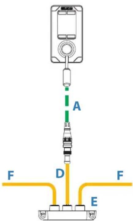
AP70/AP80 system AP24/AP28/NSE/NSS/NSO systems

For part numbers, refer to our web site.
| Item Component | ||
| A Micro-C drop cable. 6 m (19.7 ft) | Included with the unit | |
| B Micro-C T-connector | ||
| C CAN-bus backbone | ||
| D Simnet to Micro-C (female) cable. 0.5 m (1.64 ft) | ||
| E SimNet T-joiner (3p) or SimNet Multijoiner (7p) | ||
| F SimNet backbone | ||
3
Operation
Basic operation - all remotes
The keys
| Key Short press Long press (3 seconds) | ||
 | Take/request command | Activates/de-activates thrusters * |
 | Adjust illumination | Toggles day and night display illumination |
 | Turn the autopilot system to Standby mode | |
 | Toggle between available modes | Displays the Main menu(Standby mode only) |
* Only available in AP70/AP80 systems. The thrusters must be available for autopilot steering in active steering profile. See the AP70/AP80 Operator manuals for more information.
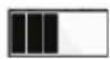
A long press is indicated with a progress bar. Keep the key pressed until all segments are filled.
Softkeys
When the menu is active or when an alarm message is displayed, the small icons below and above the keys indicate the key's function.

| Softkey Key Function | ||
 | [SADH] | OK/Accept/Acknowledge alarm |
| [225Z] |  [80D3] [80D3] | Cancel/Return to previous menu level |
| [20K3] | Mute alarm | |
| [A4BH] |  | Move upwards in menu |
| [84W0] | [G3W5] | Move downwards in menu |
The screen
The upper part of the screen shows information relevant for the autopilot mode as shown below.
| Standby NFU FU | ||
 |  |  |
| - Active heading sensor- Heading (True or Magnetic)- Current heading | - Commanded rudder angle | |
| AUTO NoDrift NAV WIND | |||
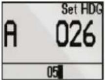 | 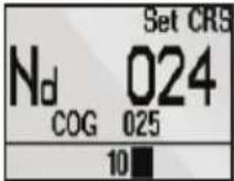 |  |  |
| - Set heading - Set course- Course Over Ground (COG) | - Bearing to next waypoint- Cross track distance (XTD), analog and graphical | - Set wind angle- Current wind angle | |


The bar in the lower part of the screen indicates always current rudder position.
Status icons
The remote's operational state is indicated with icons.
| Icon Status Description | ||
| None Active In operation | ||
 | Passive | The autopilot is operated from another control unit |
 | Locked | The autopilot is operated from another control device and this device is locked |
Switching from automatic to manual steering
Press the STBY key on active remote to switch the system from automatic mode to Standby mode.
If a menu or dialog is open, you must press and hold the STBY key to switch to Standby mode.
Turning the unit on/off
The remote units have no power key, and will be on as long as connected to a powered CAN-bus/SimNet backbone.
If the autopilot system is turned off from an autopilot control unit, the remotes will go to sleep mode. In this mode the display will be black, and it is not possible to use keys or lever. The remotes will remain in sleep mode until the system is powered on from an autopilot control unit.

Light adjustment
A single press on the light key will display the light adjustment dialog. Repeated short presses cycles through the brightness levels (0 - 10). The selection times out after 2 seconds.
A night mode which optimizes the color palette for low light conditions, is included. You switch between day and night illumination by pressing and holding the light key.
White is the default background color on display and keys for day illumination, while red is used for night. Refer “Changing default settings” on page 18.
→ Note: The brightness level is adjusted independently for day and night modes.
Activating/de-activating thrusters
If thrusters are available for autopilot control, you toggle the trusters on and off by pressing and holding the CMD key.

Active thrusters are indicated with thruster icon in the display.
→ Note: Only available in AP70/AP80 systems. The thrusters must be available for autopilot steering in active steering profile.

For more
information about multi stations, see the Operator Manual for your autopilot system.
Taking command
Take command by pressing the CMD key. When command is transferred, the autopilot system will remain in current mode.
In an open system (no command transfer restrictions), you will get immediate control on the remote unit requesting command.
In a multi-station system with active lock function, the command request must be confirmed on the active control unit before you can use the remote.
CMD

flowchart
graph LR
    A["Set HDG<br>A 113"] --> B["CMD Transfer<br>Waiting for accept<br>CMD Retry<br>Cancel"]
    B --> C["CMD transfer<br>Command requested!<br>Accept?"]
    C --> D["Yes No"]
Display on remote, and... on AP70/AP80
natural_image
Diagram of a device with a knob and handle, showing directional arrows (no text or symbols)Using the NF80
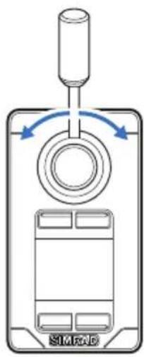
The NF80 lever has a mechanical spring that will return the lever to the mid-position when the lever is released.
You can use the NF80 in NFU, AUTO and NoDrift mode.
You can also get command if the system is in FU, NAV or Wind mode, but you cannot operate these modes from the NF80.
| Initial mode Lever moved / Resulting mode (action) | |
| Standby | NFU (rudder command)NFU |
| FU | |
| AUTO AUTO (heading change) | |
| NoDrift NoDrift (course change) | |
| NAV | No action (warning sound and information dialog) |
| Wind | |
→ Note: The Wind mode is only available if the autopilot system has been set up for sailboat. See the Installation manual for your autopilot system.


Mode selection
You toggle between available modes by repeated pressing the MODE key. The selection times out and triggers the mode shift.
When in any other mode than NFU, the first press on the MODE key will turn the system to NFU mode.
You switch to Standby from any mode by pressing the STBY key.
Non-follow up steering
In this mode you use the lever to move the rudder. The rudder will move in the same direction as the lever, and will move as long as the lever is moved from mid-position.
→ Note: See "Changing commanded rudder direction" on page 16.
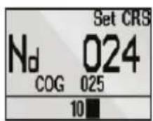
Auto and NoDrift mode
When you select AUTO/NoDrift mode, the system will continue on the heading/course read from the sensors the very moment you selected the mode.
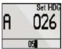
Auto mode NoDrift mode
Changing set heading/set course
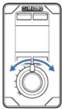
Use the lever to change set heading in AUTO mode and set course in NoDrift mode. The value will change 1° each time the lever is pressed to left or right. If you keep the lever pressed, the value automatically changes at a rate of 5° per second. Each beep indicates a 1° change.
Using the FU80
The FU lever can be rotated 70^ to port and starboard from mid-position. The lever will remain in set position, and the commanded rudder angle/heading change maintained until the lever is returned to mid-position.
You can use the FU80 in FU, AUTO and NoDrift mode.
You can also get command if the system is in NFU, NAV or Wind mode, but you cannot operate these modes from the FU80.
| Initial mode Lever moved / Resulting mode (action) | |
| Standby No action | |
| NFU No action | |
| FU FU (rudder command) | |
| AUTO AUTO (heading change) | |
| NoDrift NoDrift (course change) | |
| NAV | No action |
| Wind | |
→ Note: The Wind mode is only available if the autopilot system has been set up for sailboat. See the Installation manual for your autopilot system.

Mode selection
You toggle between available modes by repeated pressing the MODE key. The selection times out and triggers a mode shift.
When in any other mode than FU, the first press on the MODE key will turn the system to FU mode.
You switch to Standby from any mode by pressing the STBY key.

Follow-up steering
In FU mode you use the lever to set the commanded rudder angle.
⚠ Warning: To avoid unintended rudder movement you should observe the lever position (commanded rudder angle) before activating the FU mode!
To increase resolution on small rudder angle commands, the relation between the lever rotation and the commanded rudder angle is non-linear. When the lever is rotated 20^ from mid-position the rudder will be commanded 5^ to port or starboard. A 65^ lever angle will move the rudder to 40^ . Max lever rotation will give max rudder angle. Refer your autopilot installation manual for how to set max rudder angle.
The rudder will remain in set position until a new rudder angle is commanded.
AUTO and NoDrift mode
When you select AUTO/NoDrift mode, the system will continue on the heading/course read from the sensors the very moment you selected the mode.


Auto mode NoDrift mode
Changing set heading/set course
Use the lever to change set heading in AUTO mode and the set course in NoDrift mode. The value will change in steps defined by lever rotation, starting from 0.5°/second at 3° lever rotation, up to 5°/second at max lever rotation.
natural_image
Top-down schematic of a device casing with directional arrows indicating movement or force (no text or symbols)Using the QS80
The QS80 stick has a mechanical spring that will return it to mid-position when the stick is released.
You can use the QS80 in NFU, AUTO, NoDrift, NAV and Wind mode.
→ Note: The Wind mode is only available if the autopilot system has been set up for sailboat. See the Installation manual for your autopilot system.

Mode selection
You toggle between available modes by repeated pressing the MODE key. The selection times out and triggers a mode shift.
You can also use the stick to change mode as shown in the table.
| Initial mode | Stick movement / Resulting mode (action) Up Down Left/Right | ||
| Standby | AUTO | Standby(center rudder) | NFU (rudder command)NFU |
| FU | Standby | ||
| AUTO | Heading capture Course change | Heading change | |
| NoDrift | |||
| NAV | AUTO | No action | |
| Wind | Adjust relative wind angle | ||

Non-follow up steering
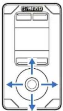
When in Standby or FU mode, press the stick left or right to switch to NFU mode and to give rudder commands. The rudder will move as long as the stick is pressed.

natural_image
Diagram of a mechanical component with a central circular feature and a downward arrow, no text or symbols present.Centering the rudder
A single downwards press on the stick while in Standby or NFU mode will command the rudder to mid-position. A short beep will sound when the rudder is centered.
Auto and NoDrift mode
When you select AUTO/NoDrift mode, the system will continue on the current heading/course the very moment you selected the mode.

Auto mode NoDrift mode

Changing set heading/set course
Use the stick to change set heading in AUTO mode and the set course in NoDrift mode. The value will change 1° each time the stick is pressed to left or right. If you keep the stick pressed, the value automatically changes at a rate of 5° per second. Each beep indicates a 1° heading/course change.

natural_image
Diagram of a mechanical component with a circular head and upward arrow, no text or symbols presentHeading capture
When in AUTO or NoDrift mode, the heading capture feature allows you to automatically cancel the turn you are in by an instant upward press on the stick. The autopilot will cancel the turn to continue on the heading read from the compass the very moment you pressed the stick.
Nav mode
If you request command and the system is in NAV mode, you will get immediate command from QS80.

If you initiate NAV from any other mode, the required heading change must be confirmed before NAV mode is accepted.
If not accepted, the system will remain in current mode.
Wind mode

→ Note: Prior to entering Wind mode the autopilot system should be operating in AUTO, with valid input from the wind transducer.
Changing set relative wind angle
Use the stick to change the set relative wind angle. The value will change 1^ each time the stick is pressed to left or right. If you keep the stick pressed, the value automatically changes at a rate of 5^ per second. Each beep indicates a 1^ heading/course change.
Changing commanded rudder direction
By default, the rudder moves in the same direction as the lever on FU80 and NF80. When you press the lever to port, the rudder is directed to port.
If the lever is rotated 180° on FU80, or if FU80/NF80 are mounted facing aft, the rudder movement can be inverted to maintain a rudder command that coincide with the lever movement.
The direction of the port/starboard commands can be changed from the Main menu. Refer "Changing default settings" on page 18.


Alarms
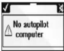
All units, both active and inactive, will notify the user if an alarm situations occurs in the autopilot system.
If the sound is enabled, any alarm message will be followed by a sound.
The CMD and LIGHT keys are used to acknowledge or mute the alarm sound.
→ Note: The alarm can only be acknowledged from an active unit.
If the cause for the alarm situation is removed, the alarm dialog will disappear when you press the CMD key.

If the cause for alarm remains after acknowledged, the alarm dialog will be replaced by an alarm icon.
If the alarm is steering critical (e.g. rudder feedback failure), the lever or stick will not operate as usual when in an alarm situation.
For alarm text, probable faults and corrective actions, refer to your autopilot Operator manual.
Restoring factory settings
You can restore all settings back to factory default from the main menu. Refer "Changing default settings" on page 18.
This is a local reset that will only affect the unit where you select the reset option.

flowchart
graph LR
    A["Main Menu\nLocal settings\nSimnet groups"] --> B["Local settings\nLanguage\nKey beeps\nLocal reset"]
    B --> C["Confirm reset"]
Maintenance
Under normal use, the remotes will require little maintenance.
If the unit requires any form of cleaning, use fresh water and a mild soap solution (not a detergent). It is important to avoid using chemical cleaners and hydrocarbons such as diesel, petrol, etc.
4
Changing default settings
The main menu
The default settings can be changed from the Main menu, activated by pressing and holding the MODE key for 3 seconds.

* Only available on FU80 and NF80.
- Local settings: Gives access to settings that applies to this unit.
• SimNet group: Assigns this unit to a SimNet group.
You remove the menu and return to standard display by pressing and holding the STBY key, or by moving the lever/stick.
→ Note: The main menu is only accessible from Standby mode.
5
Specifications
Technical specifications
→ Note: For updated technical specifications, compliance and certifications, refer to out web sites.
| Display | |
| Display resolution 128 x | 64 (H x W) |
| Display type 2" Monochrome, Bounded, Transflective | |
| Viewing direction NF80: | 12 o'clockFU80/QS80: 6 o'clock |
| Power | |
| Power supply Via CAN bus or SimNet | |
| Current consumption Off: | Network <20mA (NMEA 2000: LEN 1)On with max illumination: Network<110mA (NMEA 2000: LEN 3) |
| Interface | |
| CAN/NMEA 2000 Factory connected drop cable withMicro-C connector. 6 m (19.7 ft) | |
| SimNet Via optional SimNet to Micro-C cable | |
| Technical | |
| Housing Front: Aluminum with black plastic snap-on bezelBack: Plastic cover | |
| Temperature -25°C to +55°C (-13°F to +131°F) | |
| Weight NF80, FU80: 0.5 kg (1,10 lbs)QS80: 0.4 kg (0,88 lbs) | |
| Environmental | |
| Weather IEC 60945 sec. | 8.8, exposed, front whendesk mounted or bulkhead mountedwith optional frame.Corresponds to IP X6 |
| Compass safe distance | 0.4m (ref. IEC 60945 sec.11.2) |
| Notified compliance | CE (2004-108 EC EMC Directive)C-Tick |
Drawings
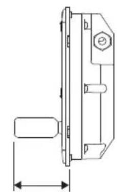
Dimension, Remotes

NF80QS80FU80
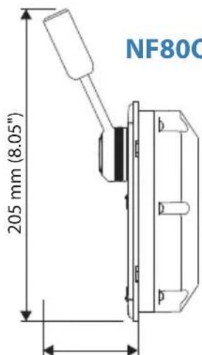
63 mm (2.46")
natural_image
Technical line drawing of a mechanical component with dimension lines (no text or symbols)51 mm (1.98")

16 mm (0.63") 63 mm (2.46")
Dimension, Bulkhead mounting frame
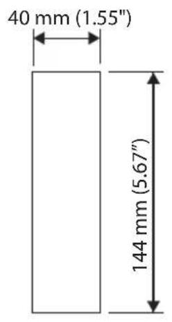
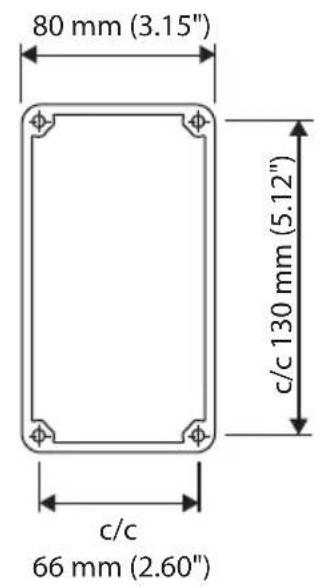
Connector pin-out

natural_image
Pure technical diagram of a mechanical or electrical component without any text, numbers, or symbols
natural_image
Technical diagram of an electronic device showing a connector with pins and wiring (no text or symbols)

Pin Color Function
| 1 Shield | ||
| 2 Red NET-S (Power source +) | ||
| 3 Black NET-C (Power source -) | ||
| 4 White NET-H (CAN high) | ||
| 5 Blue NET-L (CAN low) | ||

SIMRAD
- Preface
- Copyright
- Warranty
- Introduction
- Installation
- Operation
- Changing default settings
- Specifications
- 1
- Introduction
- About this manual
- NF80FU80QS80
- Wheelmark approval
- Parts included
- 2
- Installation
- Mounting
- Panel mount
- The bulkhead frame
- The NF80 lever
- The FU80 lever
- Wiring
- 3
- Operation
- Basic operation - all remotes
- Softkeys
- The screen
- Status icons
- Switching from automatic to manual steering
- Turning the unit on/off
- Light adjustment
- Activating/de-activating thrusters
- Taking command
- Using the NF80
- Mode selection
- Non-follow up steering
- Auto and NoDrift mode
- Changing set heading/set course
- Using the FU80
- Follow-up steering
- Using the QS80
- Centering the rudder
- Heading capture
- Nav mode
- Wind mode
- Changing set relative wind angle
- Changing commanded rudder direction
- Alarms
- Restoring factory settings
- Maintenance
- 4
- Changing default settings
- The main menu
- 5
- Specifications
- Technical specifications
- Drawings
- Dimension, Remotes
- Dimension, Bulkhead mounting frame
- Connector pin-out
- SIMRAD
Brand : SIMRAD
Model : U80
Category : Marine Electronics