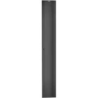
PED12B1 - Porte industrielle Panduit - Free user manual and instructions
Find the device manual for free PED12B1 Panduit in PDF.


| Product Type | Network Patch Cable |
| Brand | Panduit |
| Model | PED12B1 |
| Cable Category | Cat6 |
| Length | 1 ft (0.3 m) |
| Connector Type | RJ45 Male to RJ45 Male |
| Color | Blue |
| Jacket Material | PVC |
| Wiring Standard | T568B |
| Performance | Up to 250 MHz |
| Shielding | U/UTP (Unshielded) |
| Compliance | RoHS, TIA/EIA-568-C.2 |
| Weight | 0.02 kg |
| Operating Temperature | -20°C to 60°C |
| Application | Ethernet networking, data centers |
| Maintenance | Keep connectors clean, avoid sharp bends |
| Safety | Not for outdoor use, handle with care |
| Repairability | Not repairable, replace if damaged |
Frequently Asked Questions - PED12B1 Panduit
User questions about PED12B1 Panduit
0 question about this device. Answer the ones you know or ask your own.
Ask a new question about this device
Download the instructions for your Porte industrielle in PDF format for free! Find your manual PED12B1 - Panduit and take your electronic device back in hand. On this page are published all the documents necessary for the use of your device. PED12B1 by Panduit.
USER MANUAL PED12B1 Panduit
natural_image
Simple line drawing of a door with two handles and a handle (no text or symbols)Installation Instructions-Mounting Door to PEV Manager-7FT Sizes
Step 1: Using a flat object, remove the grommets from the rear of the door. The door brackets can now be installed.
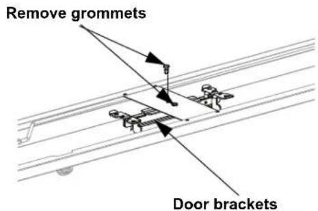
Step 2: Install door brackets to manager as shown using #12-24 screws Tighten screws to 15 in-lbs.
Step 3: Ensure that both handles are in the disengaged position.
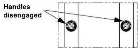
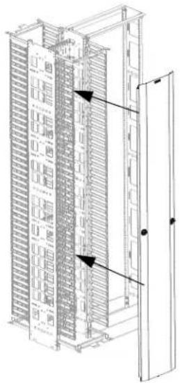
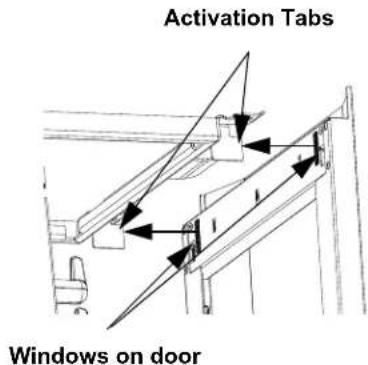
Step 4: Set door onto ends of door bracket located on the bottom of the manager. Then ensure that activation tabs on the door bracket fit into windows on the door.

Step 5: Fit activation tabs located on the top door bracket into the windows located on top of the door.
natural_image
Technical line drawing of a server rack cabinet with ventilation grilles and door (no text or symbols)
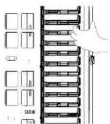
Step 6: Grasp fingers of manager with fingers and apply thumb to door face. Then squeeze together until handles pop into engaged position.
| DoorPart Number | Corresponding Vertical Manager | |
| Single Sided Dual | Sided | |
| PED6B1 PEVF6 PEV6PED8B1 PEVF8 PEV8PED10B1 | PEVF10 PEV10 | |
| PED12B1 PEVF12 PEV12 | ||
natural_image
Diagram of a hand placing a rack-mounted server into a rack, with no visible text or symbols
flowchart
graph TD
    A["Input Node"] --> C["Processing Node"]
    B["Input Node"] --> C["Processing Node"]
    C --> D["Handles engaged"]
FOR TECHNICAL SUPPORT www.panduit.com/resources/install_maintain.asp
Installation Instructions-Mounting Door to PRV Manager-7ft Sizes
Step 1: Using a flat object, remove the grommets from the rear of the door. The door brackets can now be installed.
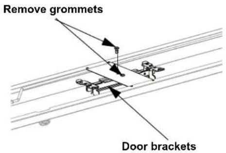
Step 2: Install door brackets to manager as shown using #12-24 screws. Use holes closest to the front of the manager. Tighten screws to 15 in-lbs.


| DoorPart Number | Corresponding Vertical Manager | |
| Single Sided Dual | Sided | |
| PED6B1 PRVF6 PRV6PED8B1 PRVF8 PRV8PED10B1 PRVF10 PRV10PED12B1 PRVF12 PRV12 | ||
Step 3: Ensure that both handles are in the disengaged position.

Step 4: Set door onto ends of door bracket located on the bottom of the manager. Then ensure that activation tabs on the door bracket fit into windows on the door.

Step 5: Fit activation tabs located on the top door bracket into the windows located on top of the door.

Step 6: Grasp fingers of manager with fingers and apply thumb to door face. Then squeeze together until handles pop into engaged position.
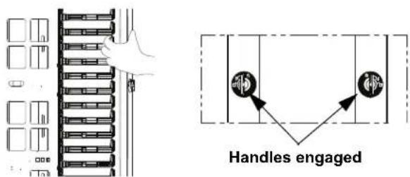
For Technical Support: www.panduit.com/resources/install_maintain.asp
Installation Instructions-Mounting Door to PEV Manager-8ft Sizes
Step 1: Remove all brackets from the door. Identify proper brackets for application and discard others.
Bracket used for mounting to PEV Manager (2 places)
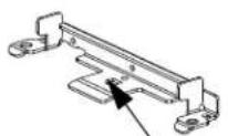
"D" Shape
Common Bracket with "D"
Brackets used for mounting to PRV Manager
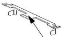
No mark
Top Bracket
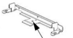
Diam
Bottom bracket
Step 2: Install door brackets to manager as shown using #12-24 screws. Use common brackets with "D" cutout on the tongue. Tighten screws to 15 in-lbs.
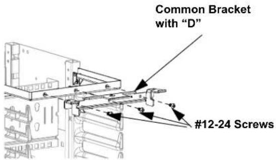
Top of manager

Bottom of manager
| DoorPart Number | Corresponding Vertical Manager | |
| Single Sided Dual | Sided | |
| PED696B1 | PEVF696 PEV696 | |
| PED896B1 | PEVF896 PEV896 | |
| PED1096B1 | PEVF1096 PEV1096 | |
| PED1296B1 | PEVF1296 PEV1296 | |
Common Bracket with "D"
Step 3: Ensure that both handles are in the disengaged position.

Step 4: Set door onto ends of door bracket located on the bottom of the manager. Then ensure that activation tabs on the door bracket fit into windows on the door.

Step 5: Fit activation tabs located on the top door bracket into the windows located on top of the door.

Windows on door
Step 6: Grasp fingers of manager with fingers and apply thumb to door face. Then squeeze together until handles pop into engaged position.

natural_image
Diagram of a server rack with multiple racks and a hand pointing to one (no text or symbols present)
flowchart
graph TD
    A["Input Node 1"] --> B{V}
    B --> C["Output Node 2"]
Handles engaged
Installation Instructions-Mounting Door to PRV Manager-8ft Sizes
Step 1: Identify the top and bottom brackets to be used only for mounting PED*96B1 to PRV managers. The bottom bracket has a diamond on the tongue. See Page 3, Step 1.
Step 3: Ensure that both handles are in the disengaged position.

Step 4: Set door onto ends of door bracket located on the bottom of the manager. Then ensure that activation tabs on the door bracket fit into windows on the door.
Step 2: Install door brackets to manager as shown using #12-24 screws. Use holes closest to the front of the manager. Tighten screws to 15 in-lbs.


Step 5: Fit activation tabs located on the top door bracket into the windows located on top of the door.


Bottom of manager
| DoorPart Number | Corresponding Vertical Manager | |
| Single Sided Dual | Sided | |
| PED696B1 | PRVF696 PRV696 | |
| PED896B1 | PRVF896 PRV896 | |
| PED1096B1 | PRVF1096 PRV1096 | |
| PED1296B1 | PRVF1296 PRV1296 | |
Step 6: Grasp fingers of manager with fingers and apply thumb to door face. Then squeeze together until handles pop into engaged position.

Door Opening Instructions
Opening door to left: Disengage right-hand latch side of door by turning handle in clockwise direction to disengage position, then swing door open to left. Push door to close.
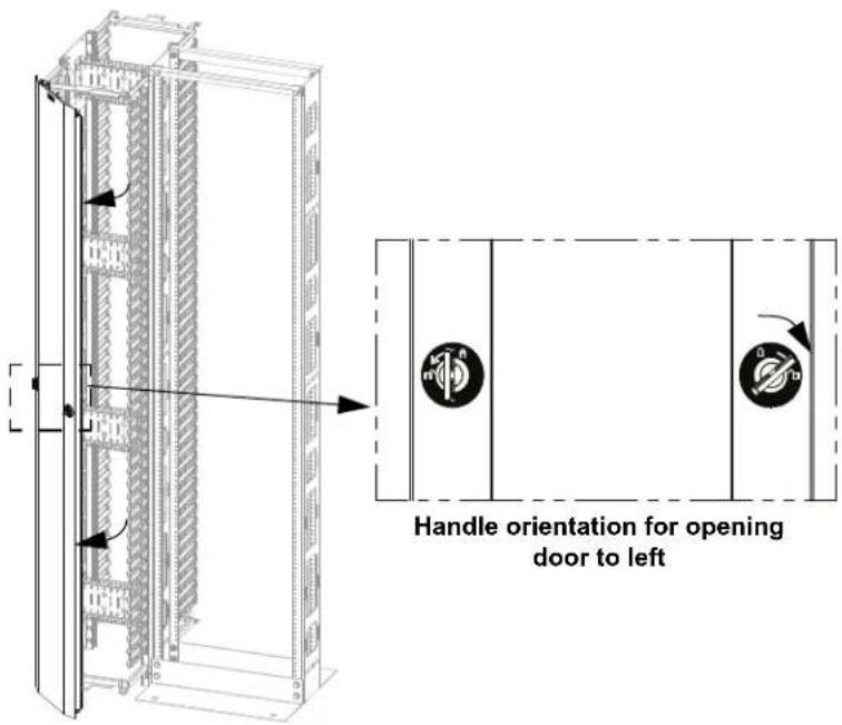
Opening door to right: Disengage left-hand side of door only by turning handle in counterclockwise direction to disengage position, then swing door open to right. Push door to close.

Door Removal Instructions
Removing door: Place both handles in disengage position, then remove door.

Handle orientation for removing door
This page intentionally left blank
- Installation Instructions-Mounting Door to PEV Manager-7FT Sizes
- Installation Instructions-Mounting Door to PRV Manager-7ft Sizes
- Installation Instructions-Mounting Door to PEV Manager-8ft Sizes
- Installation Instructions-Mounting Door to PRV Manager-8ft Sizes
- Door Opening Instructions
- Door Removal Instructions
Brand : Panduit
Model : PED12B1
Category : Porte industrielle