
321216 - Oven Mach - Free user manual and instructions
Find the device manual for free 321216 Mach in PDF.


| Product Type | Electric Rotisserie Oven (Grill Room) |
| Brand | Mach |
| Model | 321216 |
| Available Configurations | S2 (2 spits), S3 (3 spits + warming stove), S5 (5 spits + warming stove), S9 (9 spits), T16 (16 baskets), T24 (24 baskets), T36 (36 baskets) |
| Power Consumption (S5 Example) | 9.5 kW (8 kW heating + 1.5 kW warming stove) |
| Voltage | 230V 50Hz per line (1, 2, or 3 lines + neutral) |
| Heating Control | Electronic thermostat with 4-position power switch (0, low, medium, high) and timer |
| Temperature Rise (No Load) | 160°C in 12 min, 200°C in 22 min |
| Spit Rotation | Separate on/off switch for motor |
| Interior Lighting | On/off switch for light |
| Loading Capacity (S5) | 30 chickens (5 spits x 6 chickens per spit) |
| Material | Stainless steel exterior and interior |
| Installation Clearance | At least 15 cm from walls; avoid flammable objects |
| Safety Features | Fuse protection per line, earthing, glass breakage warning (do not clean hot glass with wet cloth) |
| Maintenance Frequency | Daily: drain grease, wash spits/baskets; Weekly: clean external surfaces, inspect cables |
| Cleaning Method | Warm water and dishwashing liquid for removable parts; damp cloth for exterior; do not wash appliance |
| Grease Trough Water Depth | 2–3 cm to prevent smoke and improve taste |
| Warming Stove (S3, S5, S9) | Lower compartment to keep grilled meat warm |
Frequently Asked Questions - 321216 Mach
User questions about 321216 Mach
0 question about this device. Answer the ones you know or ask your own.
Ask a new question about this device
Download the instructions for your Oven in PDF format for free! Find your manual 321216 - Mach and take your electronic device back in hand. On this page are published all the documents necessary for the use of your device. 321216 by Mach.
USER MANUAL 321216 Mach
CHICKEN GRILL (ELECTRIC)
MODEL: *321.216

natural_image
Exterior view of a stainless steel rotary oven with multiple chicken wings inside (no visible text or labels)INSTRUCTIONS FOR INSTALLATION, USE AND MAINTENANCE
S2 - S3 - S5 - S9
T16 -T24 -T36
ELECTRIC GRILL ROOM
INSTRUCTIONS FOR INSTALLATION, USE AND MAINTENANCE

This equipment must be withdrawn in accordance with Article 11(2) of Directive 2002/96/EC (WEEE)

Read and understand this Manual before operating or servicing this equipment.
1. SAFETY PRECAUTIONS
WARNING: TO PREVENT FIRE OR SHOCK HAZARD DO NOT EXPOSE THIS UNIT TO DRIPPING OR SPLASHING WATER.
The electric power switches do not completely shut off mains power from the unit, but switch operating current on and off.
2. INTRODUCTION
Congratulations on purchasing this SERGAS rotisserie.
We are sure that you will be satisfied of working with it, as it is designed to operate in heavy conditions for many years with the highest efficiency and the lowest maintenance.
As we use to all our products we took very special care for safe and economic operation. This unit is equipped with all devices for safe use of electric power according to EU and international norms. It is designed to operate with the lowest energy consumption and grill you stuff under the best sanitary conditions.
We advice you to spare a few moments to read this brief operator's manual. It may repay you in terms of improved results, or avoidance of costly mistakes.
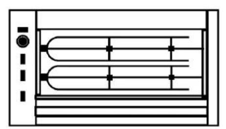
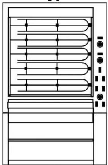
This series of electric rotisseries with spits includes the models S2, S3, S5 and S9. The S3 and S5 are delivered with a stove at the bottom where the user can keep warm the chicken that have already been grilled.
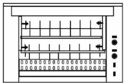
The electric rotisseries with baskets series includes the models T16, T24 and T36.
3. GENERAL DESCRIPTION
The appliance is equipped with baskets or 2, 3, 5, or 9 spits (depended of its type), with this instruction manual, and with a grease-trap tray.
natural_image
Pure technical diagram of a rectangular device with internal channels and control buttons (no text or symbols)S2

natural_image
Pure technical line drawing of a multi-tiered heating or cooling unit with no text, numbers, or symbolsS 3

natural_image
Pure schematic diagram of a heat exchanger or cooling unit with no text, numbers, or symbolsS9
natural_image
Pure technical diagram of a heat exchanger or cooling unit with no text, numbers, or symbolsS 5

natural_image
Technical diagram of a multi-tiered industrial machine with control panel and indicator lights (no text or labels)T 36
natural_image
Pure technical diagram of a vertical structure with internal grid and control elements, no text or symbols present.T 16 - T 24
Ensure that the packing you received includes everything.
4. INSTALLATION
If your appliance is not accompanied with a stove put it on a stiff table with flat surface. If it is supplied in combination with a stove put it on floor with flat surface and adjust its level by turning the adjustable legs. Take care that your appliances are in a distance at least 15cm from the nearest wall.
Special care must be taken that flammable objects (curtains, wooden, decoration etc.) are not near or above the unit.
Before you put in operation for the very first time remove the plastic coating from the stainless steel surfaces.
Electric power supply must be 230V 50 Hz per line.
Be sure that the unit is well earthed.
Our electric grill rooms can be wired with one or two or three lines and neutral. (3L + N or 2L+N or L + N).
Connections must be done according to the diagrams and wires size as they are given in the next page.
Every line supplying your appliances must have its own fuse and switch with contact separation at least 3 mm. This way they can be isolated from mains if required.
Note that all electrical works must be carried out ONLY by a qualified electrician.
4.1 WIRING
THIS WORK MUST BE CARRIED OUT ONLY BY A QUALIFIED ELECTRICIAN.
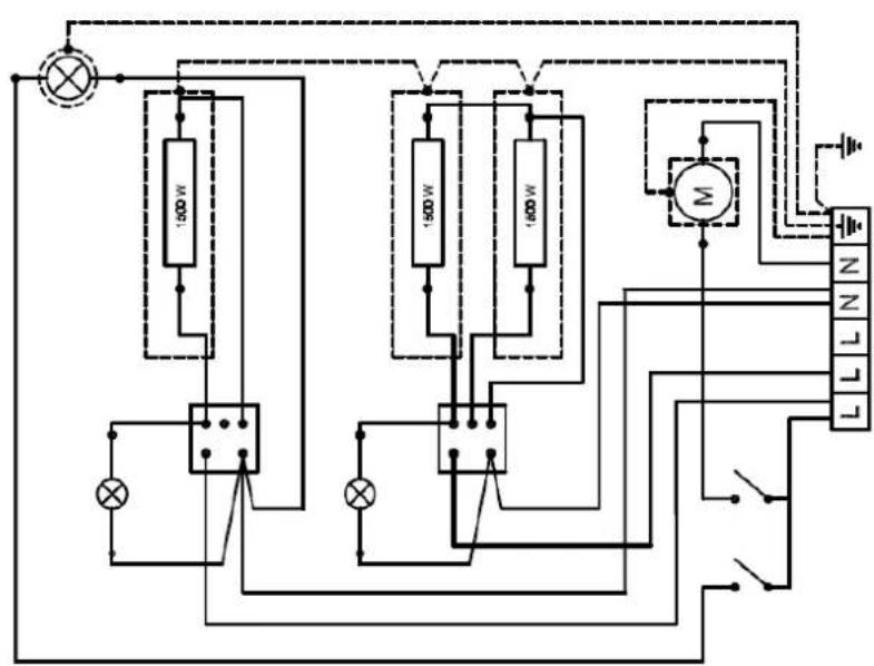
Electrical terminal is located on the bottom of the right panel, behind the switchboard. Remove the cover and connect to one or two or three lines according to the diagrams:
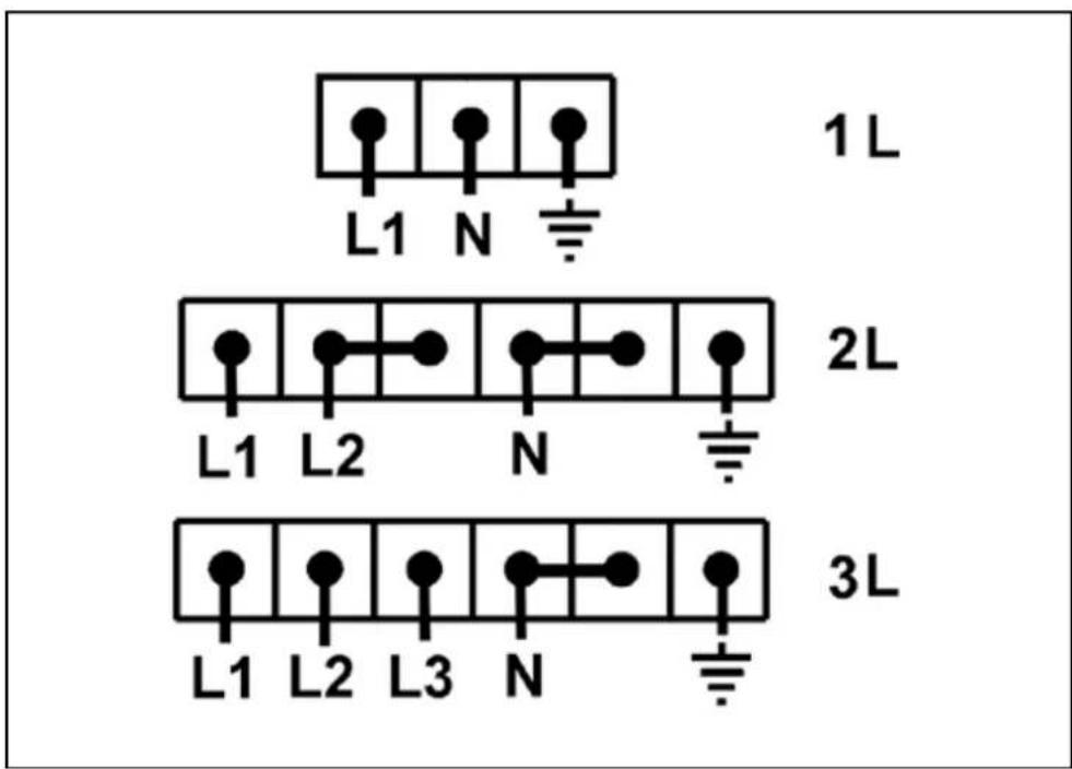
Wire sizes and fuses must be according the following board for the respective model of electric grill room:
| Model Power Lines Fuse (per line) Cable | ||||
| S 2 | 4 kW | 1 | 16 A | RN - F 3G4 |
| S 3 6 + 1,5 kW | 2 | 16 A | RN - F 4G6 | |
| 3 | 16 A | RN - F 5G6 | ||
| S 5 8 + 1,5 kW | 2 | 16 A | RN - F 4G6 | |
| 3 | 16 A | RN - F 5G6 | ||
| S 9 | 10 kW | 2 | 16 A | RN - F 4G6 |
| 3 | 16 A | RN - F 5G6 | ||
| T 16 | 4,5 kW | 1 | 16 A | RN - F 3G4 |
| T 24 | 6 kW | 2 | 16 A | RN - F 4G4 |
| T 36 | 10 kW | 2 | 16 A | RN - F 4G6 |
| 3 | 16 A | RN - F 5G6 | ||

OPERATION
5.1. DESCRIPTION OF CONTROLS
All operations of the appliance are controlled from the switchboard which is placed on the right side of the front panel except S2 where is on the left side.
On the switchboard are the switches for the control of the rotation of the spits or the baskets, the lighting switches, and the power switches controlling the heating units.
Lighting switch
Press to turn on or off the light in the grilling room.
Spit rotation control switch
Controls the operation of the spit's motors. Press to start or stop the spit's rotation.

natural_image
Simple diagram showing a light bulb, a capacitor, and a vertical control panel (no text or symbols)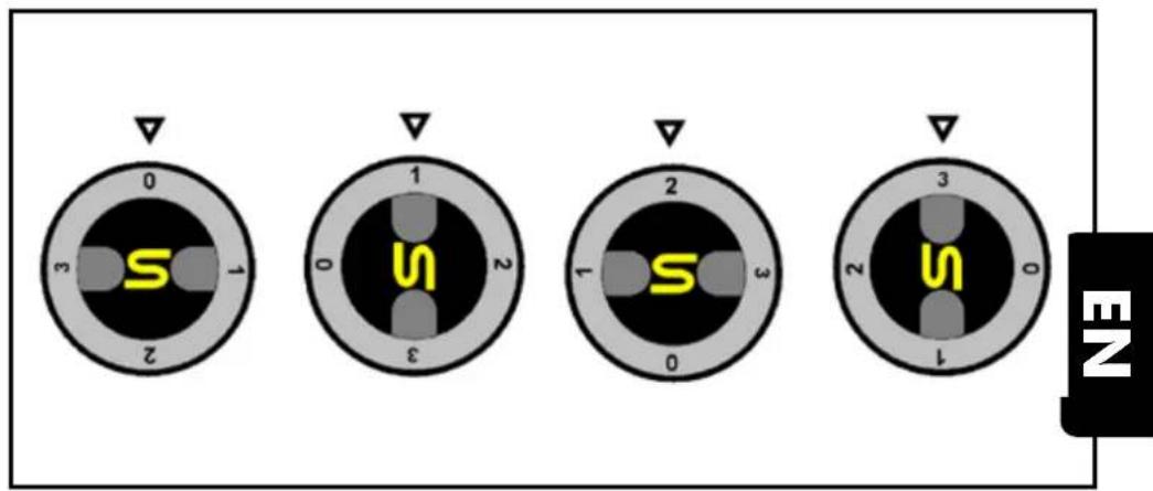
Power switch
It controls the electric power of two or one (the top switch in S5 or in the stoves) heating units and can be turned in four positions:
The position 0 where the switch is closed.
The position 3 where both heating units controlled by this switch are in full operation. The appliance grills medium or big amount of meat - normal grilling operation.
The position 2 where one heating unit in full operation and the other is off. The appliance grills low amount of meat. If the switch controls only one unit that is in full operation.
The position 1 where both heating units are in low power operation. The appliance keeps warm the already grilled meat. If the switch controls only one heating unit then in the position 1 it is off.
If your appliance is equipped with an electronic thermostat, select the desired temperature by pressing the button L1.
First appears the indication 1SP and after 2 sec the selected temperature. To increase it press L2 and to decrease it press L1.
If no button is pressed for a few seconds thermostat returns to the initial indication.


To start the appliance's operation (one circle of operation) press the start button
To define the duration of a circle of operation press the button >> for increasing or the button << for decreasing it.
To operate the appliance with no time limit press for 3 sec the button (manual operation).
To return in timed operation press again the same button for 3 sec.
If no button is pressed for a few seconds timer returns to the initial indication.
At no load condition the appliance rises up to 160irc C in 12 minutes and to 200irc C in 22 minutes.

5.2 LOADING THE SPITS
Put the chicken in the spit according the following sketch. To do it put first three chicken and fix the middle hook. Then put the rest three chickens, fix the outer hook and secure them with the wing screw.

natural_image
Line drawing of a hand operating a mechanical tool with a circular component nearby (no text or symbols)Put the loaded spit in the unit and fix it in its position. To do it fix first the left-hand edge in the bearing and then the right-hand edge to the respective hanger.
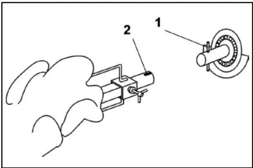
The spit is secured in its position when spit's groove (2) comes inside the holder's pin (1) according to the sketch above. Now the unit is ready to start grilling.

5.3 LOADING THE BASKETS
Put the chicken in the baskets so that the hook comes inside their body according the following sketch. In each basket can be 4 chicken. If you wish to grill less chicken than the available positions share them in all baskets to have a uniform load to the axle.
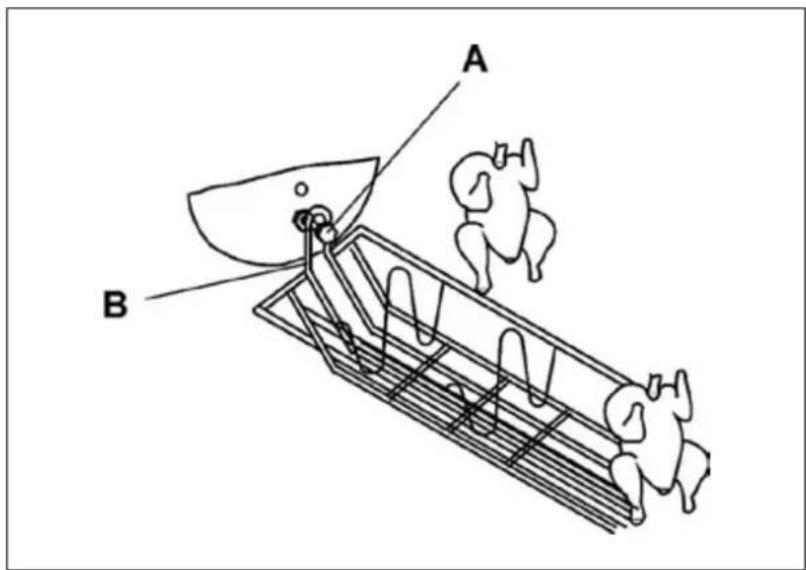
Bring the basket in the unit and hang first one and then the other hooks (A) on the bolts (B). Press the motor's switch to rotate the axle and bring the next loading position.
natural_image
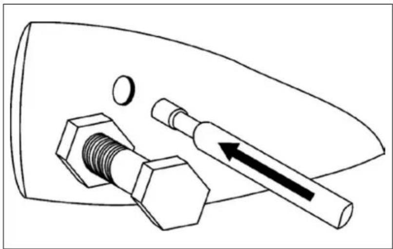
Technical line drawing of a mechanical component with bolts and a shaft, no text or symbols presentThe T16, T24 and T36 are equipped also with a spit (single bar) that you can use to grill your specialties. In the sketch above you can see how to fix it on the disc.
5.4 GRILLING
Pull the sliding grease trough and put in it as much water as is necessary to be covered in a depth of 2 – 3 cm.
This way the grease which falls from the meat, when the grilling starts, does not make smoke in the grilling room and the meat gets better taste.
Close the doors and supply full power to all heaters.
Press the switches controlling the spit rotating motor.
The grilling starts.
Inspect the grilling proceeding and if necessary decrease the heat by switching off the heaters.
If you own the S3, S5 or S9 you can store the grilled meat in the warming room which is in the lower part of the unit, and load it again to grill a second batch of chicken.
Always after serving part of the grilled chicken before you start the spits or baskets rotation again be sure that they are well secured in their hangers.
Always, before you start grilling, be sure that the sliding grease trough is covered with water in a depth of 2 – 3 cm and that is not full of grease that could overflow.
6. MAINTENANCE
Every when you finish grilling switch off the heaters and drain the grease from the grease collecting trough.
Remove the spits or the baskets and wash them with warm water and dishwashing liquid.
After the unit becomes cold disconnect it from mains by turning off the corresponding switch in your installation, and clean with a wet sponge the inner surfaces.
When the unit becomes absolutely cold, clean all the glass surfaces with glass cleaning liquid or warm water and dishwashing liquid.
Be sure that the glasses are absolutely dry before you put the unit in operation again.
Never wash the glasses and never touch them with something wet when they are warm. This could cause their breaking
Remove the grease collecting trough and wash it with warm water and dishwashing liquid.
Dry all parts you've washed before you put them back to their place and leave the unit 10-15 minutes to become dry before you plug it again to mains.
Once a week disconnect the unit from mains and clean with a lightly wet clothe the external surfaces. Leave it 10 – 15 minutes to become absolutely dry before you plug it again to mains and put it in operation.
Never wash the appliance. This could expose the user to electric shock's hazard.
Once a week inspect the cables connecting it to the mains and be sure that they are always in good condition.


flowchart
graph TD
    A["Input"] --> B["Node 1"]
    B --> C["W"]
    C --> D["Node 2"]
    D --> E["W"]
    E --> F["Node 3"]
    F --> G["W"]
    G --> H["Node 4"]
    H --> I["W"]
    I --> J["Node 5"]
    J --> K["W"]
    K --> L["Output"]
    style A fill:#f9f,stroke:#333
    style B fill:#ccf,stroke:#333
    style C fill:#cfc,stroke:#333
    style D fill:#fcc,stroke:#333
    style E fill:#cff,stroke:#333
    style F fill:#ffc,stroke:#333
    style G fill:#cfc,stroke:#333
    style H fill:#fcc,stroke:#333
    style I fill:#ffc,stroke:#333
    style J fill:#cfc,stroke:#333
    style K fill:#fcc,stroke:#333
    style L fill:#ffc,stroke:#333
6S

flowchart
graph TD
    A["Terminal N"] --> B["Motor Control"]
    C["Terminal M"] --> D["Inductor M 2000"]
    E["Terminal M"] --> F["Inductor M 2000"]
    G["Terminal M"] --> H["Inductor M 1"]
    I["Terminal M"] --> J["Inductor M"]
    K["Terminal N"] --> L["Switch"]
    M["Terminal T"] --> N["Switch"]
    O["Terminal T"] --> P["Switch"]
    Q["Terminal T"] --> R["Switch"]
    S["Terminal T"] --> T["Switch"]
    U["Terminal T"] --> V["Switch"]
    W["Terminal T"] --> X["Switch"]
    Y["Terminal T"] --> Z["Switch"]
    AA["Terminal T"] --> AB["Switch"]
    AC["Terminal T"] --> AD["Switch"]
    AE["Terminal T"] --> AF["Switch"]
    AG["Terminal T"] --> AH["Switch"]
    AI["Terminal T"] --> AJ["Switch"]
    AK["Terminal T"] --> AL["Switch"]
    AM["Terminal T"] --> AN["Switch"]
    AO["Terminal T"] --> AP["Switch"]
    AQ["Terminal T"] --> AR["Switch"]
    AS["Terminal T"] --> AT["Switch"]
    AU["Terminal T"] --> AV["Switch"]
    AW["Terminal T"] --> AX["Switch"]
    AY["Power Source"] --> AZ["Ground"]
T36
flowchart
graph TD
    A["Power Source"] --> B["N"]
    B --> C["M"]
    C --> D["Motor 1"]
    C --> E["M"]
    E --> F["Motor 2"]
    E --> G["Motor 3"]
    F --> H["Light Bulb"]
    G --> I["Light Bulb"]
    H --> J["Switch"]
    I --> K["Switch"]
    L["Power Supply"] --> M["W"]
    M --> N["Motor 1"]
    M --> O["Motor 2"]
    M --> P["Motor 3"]
    M --> Q["Motor 4"]
T16-T24
S2 S3 S5

flowchart
graph TD
    A["Power Source"] --> B["Switch"]
    B --> C{Motor Control}
    C --> D["Motor 1"]
    C --> E["Motor 2"]
    C --> F["Motor 3"]
    D --> G["Switch"]
    E --> H["Switch"]
    F --> I["Switch"]
    G --> J["Power Supply"]
    H --> J
    I --> J
    J --> K["Output"]
    style A fill:#f9f,stroke:#333
    style K fill:#ccf,stroke:#333

flowchart
graph TD
    A["Power Source"] --> B["Switch"]
    B --> C{Switch}
    C --> D["Relays"]
    D --> E["M"]
    D --> F["N"]
    E --> G[" meters "]
    F --> H[" meters "]
    G --> I[" 2000 V "]
    H --> J[" 2000 V "]
    I --> K[" 2000 V "]
    J --> L[" 2000 V "]
    K --> M[" 2000 V "]
    L --> N[" 2000 V "]
    M --> O[" 2000 V "]
    N --> P[" 2000 V "]
    O --> Q[" 2000 V "]
    P --> R[" 2000 V "]
    Q --> S[" 2000 V "]
    R --> T[" 2000 V "]
    S --> U[" 2000 V "]
    T --> V[" 2000 V "]
    U --> W[" 2000 V "]
    V --> X[" 2000 V "]
    W --> Y[" 2000 V "]
    X --> Z[" 2000 V "]

flowchart
graph TD
    A["Power Source"] --> B["Switch 1"]
    A --> C["Switch 2"]
    A --> D["Switch 3"]
    A --> E["Switch 4"]
    A --> F["Switch 5"]
    A --> G["Switch 6"]
    A --> H["Switch 7"]
    A --> I["Switch 8"]
    A --> J["Switch 9"]
    A --> K["Switch 10"]
    A --> L["Switch 11"]
    A --> M["Switch 12"]
    A --> N["Switch 13"]
    A --> O["Switch 14"]
    A --> P["Switch 15"]
    A --> Q["Switch 16"]
    A --> R["Switch 17"]
    A --> S["Switch 18"]
    A --> T["Switch 19"]
    A --> U["Switch 20"]
    A --> V["Switch 21"]
    A --> W["Switch 22"]
    A --> X["Switch 23"]
    A --> Y["Switch 24"]
    A --> Z["Switch 25"]
    A --> AA["Switch 26"]
    A --> AB["Switch 27"]
    A --> AC["Switch 28"]
    A --> AD["Switch 29"]
    A --> AE["Switch 30"]
    A --> AF["Switch 31"]
    A --> AG["Switch 32"]
    A --> AH["Switch 33"]
    A --> AI["Switch 34"]
    A --> AJ["Switch 35"]
    A --> AK["Switch 36"]
    A --> AL["Switch 37"]
    A --> AM["Switch 38"]
    A --> AN["Switch 39"]
    A --> AO["Switch 40"]
    A --> AP["Switch 41"]
    A --> AQ["Switch 42"]
    A --> AR["Switch 43"]
    A --> AS["Switch 44"]
    A --> AT["Switch 45"]
    A --> AU["Switch 46"]
    A --> AV["Switch 47"]
    A --> AW["Switch 48"]
    A --> AX["Switch 49"]
    A --> AY["Switch 50"]
    A --> AZ["Switch 51"]
    A --> BA["Switch 52"]
    A --> BB["Switch 53"]
    A --> BC["Switch 54"]
    A --> BD["Switch 55"]
    A --> BE["Switch 56"]
    A --> BF["Switch 57"]
    A --> BG["Switch 58"]
    A --> BH["Switch 59"]
    A --> BI["Switch 60"]
    A --> BJ["Switch 61"]
    A --> BK["Switch 62"]
    A --> BL["Switch 63"]
    A --> BM["Switch 64"]
    A --> BN["Switch 65"]
    A --> BO["Switch 66"]
    A --> BP["Switch 67"]
    A --> BQ["Switch 68"]
    A --> BR["Switch 69"]
    A --> BS["Switch 70"]
    A --> BT["Switch 71"]
    A --> BU["Switch 72"]
    A --> BV["Switch 73"]
    A --> BW["Switch 74"]
    A --> BX["Switch 75"]
    A --> BY["Switch 76"]
    A --> BZ["Switch 77"]
    A --> CA["Switch 78"]
    A --> CB["Switch 79"]
    A --> CC["Switch 80"]
    A --> CD["Switch 81"]
    A --> CE["Switch 82"]
    A --> CF["Switch 83"]
    A --> CG["Switch 84"]
    A --> CH["Switch 85"]
    A --> CI["Switch 86"]
    A --> CJ["Switch 87"]
    A --> CK["Switch 88"]
    A --> CL["Switch 89"]
    A --> CM["Switch 90"]
    A --> CN["Switch 91"]
    A --> CO["Switch 92"]
    A --> CP["Switch 93"]
    A --> CQ["Switch 94"]
    A --> CR["Switch 95"]
    A --> CS["Switch 96"]
    A --> CT["Switch 97"]
    A --> CU["Switch 98"]
    A --> CV["Switch 99"]
    A --> CW["Switch 100"]


- CHICKEN GRILL (ELECTRIC)
- INSTRUCTIONS FOR INSTALLATION, USE AND MAINTENANCE
- S2 - S3 - S5 - S9
- T16 -T24 -T36
- ELECTRIC GRILL ROOM
- SAFETY PRECAUTIONS
- INTRODUCTION
- GENERAL DESCRIPTION
- INSTALLATION
- WIRING
- OPERATION
- DESCRIPTION OF CONTROLS
- Lighting switch
- Spit rotation control switch
- Power switch
- LOADING THE SPITS
- LOADING THE BASKETS
- GRILLING
- MAINTENANCE
Brand : Mach
Model : 321216
Category : Oven