
5D40 - Conditionneur de fréquence Daytronic - Free user manual and instructions
Find the device manual for free 5D40 Daytronic in PDF.


| Product Type | Signal Conditioner Module (Frequency-to-Voltage Converter) |
| Model | 5D40 (0-5 VDC output) / 5D40V (0-10 VDC output) |
| Dimensions | Compact extruded aluminum case (see manual Fig. 1) |
| Weight | Approximately 200 g |
| Power Supply | 24 VDC ±10%, 140 mA typical, 160 mA max |
| Input Signal | AC or unipolar pulse (sine, square, irregular, TTL); 50 mV to 250 V RMS |
| Input Ranges (Nominal Full-Scale) | 200 Hz to 400 kHz (selectable via RNG command) |
| Analog Output | 0-5 VDC (5D40) or 0-10 VDC (5D40V); filtered; two outputs (A continuous, B switchable on 5D40) |
| Accuracy | ±0.04% of full scale (0.1% to 36% range); ±0.02% above 36% |
| Cycle-by-Cycle Tracking | Automatic for fast frequency changes; adjustable tracking window width (1.0% to 9.9% of full scale) |
| Calibration | Absolute (software-based) and Two-Point (deadweight) calibration; midscale linearity correction |
| Isolation | 1500 VAC between input and output; 1500 VAC between I/O and power/communications |
| ESD Protection | Up to 4 kV on all connections |
| Input Overvoltage Protection | Up to 240 VAC RMS on signal and excitation lines |
| Operating Temperature | -10°C to 70°C (14°F to 158°F) |
| Operating Humidity | 5% to 95% noncondensing |
| Mounting | Panel, DIN rail (35 mm), or motherboard (Daytronic 5DMB series) |
| Connectors | DB25 (5D40) or screw-terminal (5D40V/5D40S); separate transducer connector |
| Software | 5D Configurator (Windows); RS232 communication (19,200 baud, 8N1) |
| Status Indicator | Green (normal), Yellow (overrange), Red (fault), flashing for communications active |
| Maintenance | Clean with dry cloth; no internal user-serviceable parts; periodic calibration recommended |
| Safety | Designed with isolation and protection to safe limits; follow manual for proper grounding |
| Spare Parts & Repairability | Contact Daytronic or authorized service center for spare parts and repair |
Frequently Asked Questions - 5D40 Daytronic
User questions about 5D40 Daytronic
0 question about this device. Answer the ones you know or ask your own.
Ask a new question about this device
Download the instructions for your Conditionneur de fréquence in PDF format for free! Find your manual 5D40 - Daytronic and take your electronic device back in hand. On this page are published all the documents necessary for the use of your device. 5D40 by Daytronic.
USER MANUAL 5D40 Daytronic
VERSION SB.1 MANUAL PART NO. 92327
Copyright © 2002, 2005, Daytronic Corporation. All rights reserved.
No part of this document may be reprinted, reproduced, or used in any form or by any electronic, mechanical, or other means, including photocopying and recording, or in any information storage and retrieval system, without permission in writing from Daytronic Corporation.
All specifications are subject to change without notice.
TABLE OF CONTENTS
1 INTRODUCTION
1.A General Description and Specifications 5D40(V) - 1.1
1.B Mounting the Model 5D40(V) 5D40(V) - 1.4
1.c Installing and Running the 5D Configurator Software 5D40(V) - 1.4
2 CONNECTIONS
2.A Introduction 5D40(V) - 2.1
2.B Power and Ground Connections 5D40(V) - 2.2
2.c Serial Communications Connections 5D40(V) - 2.3
2.D Transducer Connections 5D40(V) - 2.4
2.E Analog Output Connections 5D40(V) - 2.7
2.F Logic Input Connection 5D40(V) - 2.8
3 CONFIGURATION AND CALIBRATION
3.A Using the 5D Configurator 5D40(V) - 3.1
3.B Summary of Configurator Menus 5D40(V) - 3.2
3.c Overview of the Configuration Process 5D40(V) - 3.3
3.D 5D40(V) Calibration 5D40(V) - 3.5
4 OPERATING CONSIDERATIONS
4.A Sending a Command to the 5D40(V) 5D40(V) - 4.1
5 TROUBLESHOOTING
5.A Interpreting the Status Indicator Light 5D40(V) - 5.1
5.B Interpreting the Module Diagnostic Code 5D40(V) - 5.1
APPENDIX A SUMMARY OF 5D40(V) MNEMONIC COMMANDS
A.1 Command and Response Syntax 5D40(V) - A.1
A.2 5D40(V) Setup and Interrogation Commands 5D40(V) - A.2
A.3 5D40(V) Imperative Commands .... 5D40(V) - A.4
APPENDIX B 5D40(V) ABSOLUTE CALIBRATION CALCULATIONS
5D40(V) - B.1
ILLUSTRATIONS
Fig. 1 5D Dimensions .... 5D40(V) - 1.3
Fig. 2 5D Mounting Features 5D40(V) - 1.4
Fig. 3 5D Power, Configuration, Logic, and Analog Output Connections
Fig. 3.a Standard DB25 Connector (Model 5D40) 5D40(V) - 2.1
Fig. 3.b Alternative Screw-Terminal Connection (Models 5D40V and 5D40S) .... 5D40(V) - 2.1
Fig. 4 General 5D Network Connections 5D40(V) - 2.2
Fig. 5 5D Power / Serial Communications Connections 5D40(V) - 2.3
Fig. 6 Model 5D40(V) Transducer Connections
Fig. 6.a Input from Magnetic Pickup, Using Twisted-Pair Cable 5D40(V) - 2.4
Fig. 6.b Input from Magnetic Pickup, Using Coaxial Cable 5D40(V) - 2.5
Fig. 6.c Input from Generic TTL Device 5D40(V) - 2.5
Fig. 6.d Input from Zero-Velocity Sensor with 5-Volt Excitation 5D40(V) - 2.6
Fig. 7 5D Analog Output Connections 5D40(V) - 2.7
Fig. 8 Model 5D40 Logic Input Connections
Fig. 8.a Switch Closure, No External Supply 5D40(V) - 2.8
Fig. 8.b Active TTL Logic 5D40(V) - 2.8
Fig. 9 Absolute Calibration Page for the Model 5D40(V) 5D40(V) - 3.7
Fig. 10 Linearity Correction in the Positive Domain 5D40(V) - 3.9
Fig. 11 Two-Point Calibration Page for the Model 5D40(V) 5D40(V) - 3.10
TABLES
Table 1 Model 5D40(V) Ranges (Nominal) 5D40(V) - 1.2
Table 2 “Practical” 5D40(V) Range (RNG) Settings .... 5D40(V) - B.1
1. INTRODUCTION
1.A GENERAL DESCRIPTION AND SPECIFICATIONS
A prime member of Daytronic's family of pluggable SIGNAL CONDITIONER MODULES, the Model 5D40(V) is used with conventional frequency-generating transducers, such as tachometer pickups, turbine flowmeters, transistor or logic-circuit drivers, and "zero-velocity" (true digital output) sensors.
The 5D40 delivers filtered analog output of 0 - 5 VDC, while the 5D40V produces 0 - 10 VDC. Both models accept sine, square, and irregular waveform inputs, plus TTL. Exceptional signal stability and accuracy over an unusually wide dynamic range—down to 0.1% of full scale—are achieved through
- adjustable "cycle-by-cycle" tracking
- selectable input threshold levels
- capacitive coupling for magnetic pickup inputs
- "absolute" software-based calibration
• effective signal isolation & ESD protection
Each compact 5D40(V) module is a self-contained, easily configurable, physically hardened instrument. With pluggable screw-terminal connectors for easy installation and I/O field wiring, it can be used as an individual or "in-line" signal conditioner, or can reside in a host device to complete an effective, economical front-end solution. Connecting directly to its source sensor via simple pinout, the module powers, conditions, isolates, filters, and scales its sensor's frequency signal to a standardized 5-V or 10-V level, making it usable as input to a PC, PLC, or other device for further processing, display, recording, etc. High output accuracy over a wide temperature range guarantees repeatable sensor signal integrity.
The 5D40(V)'s extruded-aluminum case has guides for insertion into a housing. It also provides an edge screw boss for securing the unit independently to a fixture or clipping it to a DIN rail. Or it can be plugged into a "motherboard" backplane for multiplexing into an analog input device, via the Analog Output / Power / Communications Connector described in Section 2.A. ^1
1 See the Model 5DMB Instruction Manual for a complete description of the Daytronic Model 5DMB-8 and Model 5DMB-16 cabinet-mountable motherboards.
^2 A larger 10- F coupling is also provided (if required) for removal of relatively large amounts of ± DC offset.
3 The effective trigger levels are automatically adjusted to 75% and 25% of the peak-to-peak input voltage on a "cycle-by-cycle" basis. Reliable triggering is therefore obtained for wave-shapes that cross those regions once per cycle. A differential input amplifier with selectable gain precedes the Schmitt trigger.
In addition to its standardized pulse-averaging circuit, the Model 5D40(V) incorporates a new frequency-to-voltage conversion strategy that results in vastly superior overall dynamic response to changes in input frequency.
For inputs greater than 36% of the module's nominal full-scale frequency setting—and which are relatively constant or only slowly changing—the pulse-averaging filter is sufficient for accurate, stable measurement. "Cycle-by-cycle" tracking. however, is automatically invoked on detection of any cycle period that indicates a change in frequency that is greater than a user-specified "tracking window width" (expressed as percent of full scale). It also switches on automatically when the input level drops below 36% of full scale, where the traditional pulse-averaging method normally yields increasingly "noisier" answers.
When the tracking window is in operation, a special circuit generates a "period reciprocal" output voltage (proportional to "1/t"), and a special comparator then determines whether, with respect to the present "1/t" value, each incoming pulse arrives within the current tracking window. If such is the case, no output adjustment is made. However, if a pulse comes too early (before the window "opens"), the present output is updated to approximate the "1/t" value at the pulse's time of arrival. If the expected pulse has not yet arrived when the window period has elapsed, the output is made to track the "1/t" voltage until the pulse is detected.
When the determination of average frequency is of prime concern, the user can specify a relatively wide tracking window, thereby ignoring any input variations that are smaller than that width. To ignore extraneous dynamic components (not intrinsic to the measured process) in higher-level frequency measurements, cycle-by-cycle tracking may even be turned off altogether. In this case, the tracking window is effectively infinite. If, on the other hand, there is no significant input variation, the window width can be reduced to a minimum to produce even quicker response.
Capacitive shunting (or "coupling") of 0.1 microfarads is provided for magnetic pickup inputs, to eliminate false triggering by signal noise. ^2 For waveform inputs from approximately 2 Hz to 200 kHz, a "Smart Schmitt" trigger—in conjunction with a variable-sensitivity amplifier—adapts to signal amplitudes from 50 mV to 250 V, thus ensuring reliable triggering when the input is at the low end of the voltage range. ^3
For both the Model 5D40V and the Model 5D40S (the "S" Option version of the Model 5D40), a 10-pin header for a Phoenix Style screw-terminal connector replaces
1. INTRODUCTION
the Model 5D40's standard DB25 connector for the module's power, configuration, logic, and output wiring—see Fig. 3.b. Ensuring secure cable connections to individual 5D modules, these versions are intended primarily for single-point or single-mount module applications. Since the logic "enable" line is not provided in this case, both analog outputs are continuously available for both the 5D40V and the 5D40S.
Internal "ABSOLUTE" CALIBRATION ensures high accuracies, without elaborate trial and error procedures. Thus, to calibrate a 5D40(V), no "deadweighting" is required; as explained in Section 3.D, you need only use the configuration software provided with the unit to specify the desired output in Hz or RPM to correspond to the module's full-scale 5-VDC or 10-VDC output (for RPM, the pulses per revolution must also be entered). A zero offset term may be specified, expressed either in Hz (RPM) or millivolts.
Conventional TWO-POINT (DEADWEIGHT) CALIBRATION may be applied, if desired, to improve on the "absolute" calculations, when there are at least two
independently and accurately known calibration points ("ZERO" and "SPAN"). An additional internal midscale linearity correction can also be made.
Guaranteed "absolute" calibration accuracy for a properly configured 5D40(V) is given in the Specifications, below. By virtue of the unusually high stability of the 5D40(V) instrument, even higher accuracies can be achieved with additional high-precision two-point calibration.
Employing the run-time version of Microsoft® Access 2000, the 5D CONFIGURATOR software supplied with the Model 5D40(V) makes short work of module setup. Communicating via RS232 link, the Configurator lets you define, store, edit, download, upload, and manage any number of "configurations" for a connected array of one to 16 independent 5D modules. It also lets you perform selected run-time operations, including both "absolute" and two-point (deadweight) calibration, plus the sending of standard mnemonic commands to a specific module.
MODEL 5D40(V) SPECIFICATIONS
Housing: Extruded aluminum casing; mountable to panel, fixture, or DIN-rail
Dimensions: See Fig. 1, below
Power Requirements: 24 VDC ± 10%; 140 mA nom.; 160 mA max.
Input Overvoltage Protection: Up to 240 VAC rms on all Signal and Excitation lines ^1
ESD Protection: Up to 4 kV on all connections
Isolation: 1500 VAC between input and output terminals; 1500 VAC between I/O terminals and power supply / communications terminals
Operating Temperature Range: -10^ C to 70^ C ( 14^ F to 158^ F)
Operating Relative Humidity: 5% to 95%, noncondensing
Table 1 Model 5D40(V) Ranges (Nominal) ^3
| Range Range(Hz, full-scale) (Hz, full-scale) |
| 200 10000 |
| 300 15000 |
| 400 20000 |
| 500 30000 |
| 750 40000 |
| 1000 60000 |
| 1500 80000 |
| 2000 100000 |
| 3000 150000 |
| 4000 200000 |
| 6000 300000 |
| 8000 400000 |
Frequency Input:
Type: Any AC or unipolar pulse signal, grounded or floating, regardless of waveform
Sensitivity: "Smart Schmitt" trigger and differential amplifier with four selectable gains accommodate signals from 50 mV to 250 V
Ranges (Nominal, Full-Scale): See table; selectable when the 5D40(V) is configured (NOTE: the highest range selection accommodates actual inputs as high as 600 kHz ^2 )
Excitation: 10 VDC (= ±5 VDC) ± 2% @ up to 70 mA
Accuracy: (as % of full scale overall expected maximum error, following calibration):
From approximately 0.1% to 36% of input range: ±0.04% Above 36% of input range: ±0.02%
Differential Amplifier:
Input Impedance: Greater than 200 kΩ on all ranges
TTL Input: Internally pulled up to +5 V through 22 kΩ; overvoltage protection to +20 V
Offset: Initial: ±0.02% of full scale; vs. temperature: ±25 ppm/°C; vs. time: ±10 ppm/month
Gain Accuracy: ±0.02% of full scale typical, following calibration
(cont'd)
1 Except for the two "capacitive coupling" lines.
2 See Table 2 in Appendix B for the "practical" ranges that apply to the 5D40(V) RANGE (RNG) setting.
3 Every range above 3000 Hz is derived from either the 2000-Hz or 3000-Hz ("source") range via division of the input signal. For this reason, the ripple frequency and speed of output response for any range above 3000 Hz will be determined by the pulse-averaging filter employed by the source range.
1. INTRODUCTION
Gain Stability: vs. temperature: ±25 ppm/°C; vs. time: ±10 ppm/month
Analog Filters: 0.2, 2, 20, 200, or 2000 Hz, independently selectable for each output*
Analog Outputs: Filtered 0 to 5 VDC (for the Model 5D40) or 0 to 10 VDC (for the Model 5D40V), with linearity maintained for 20% overrange. For the Model 5D40, Output A is continuous and Output B is switchable via logic "Enable" line (see Section 2.F). The "Enable" line is not available for the Model 5D40V or the Model 5D40 with "S" Option; for these models, both outputs are continuously available.
Logic Input (Enable) for Model 5D40 (only): Nominal 0 - 5 V, where 5 V = Logic 1 ("true"); ±25 V without damage; noise immunity 1 V; internal pull-up nom. 5 kΩ; input assumes Logic 1 state in the absence of connection
Status Indicator Light: Green/Yellow/Red; indicates module input and communications status (see Section 5.A)
* See note (3) on the previous page.

Fig. 1 5D Dimensions
Power, Configuration, Logic, and Analog Output Connector* (see Figs. 4, 5, 7, and 8)
* Standard DB25 connector shown; "single-point" screw-terminal connection is provided with Model 5D40V or 5D40S (see Fig. 3.b).
1. INTRODUCTION
1.B MOUNTING THE MODEL 5D40(V)
In most applications, a Model 5D40(V) unit will be either individually mounted to a fixture, clipped to a European DIN standard 35-mm rail, or plugged into a "mother-board" backplane assembly (such as a Daytronic "5DMB") to be part of an interconnected array of up to 16 "5D" modules. See the Model 5DMB Instruction Manual for installing 5D modules on a Daytronic Model 5DMB-8 or 5DMB-16 cabinet-mountable motherboard.
As shown in Fig. 2, mounting holes are provided on the side of the unit for securing it to the user's fixture or for attaching a conventional DIN clip.*
The 5D40(V)'s captive mounting screws are normally used only when its DB25 connector is plugged into a Daytronic "5DMB" or other host backplane / instrument that provides suitable guide rails (see the Model 5DMB Instruction Manual).
* The holes are spaced to accommodate the standard JIT Component "JSDA" clip (available from Daytronic).
Fig. 2
5D Mounting Features

1.C INSTALLING AND RUNNING THE 5D CONFIGURATOR SOFTWARE
PLEASE NOTE: This software requires an operating system of Windows 95 or higher which takes approximately 3.5 MB of hard-drive space.
For more information on "Using the 5D Configurator," see Section 3.A of this manual.
To INSTALL the 5D Configurator Software,
- Make sure to close all applications before starting the installation. Use Windows Explorer to access programs.
-
Insert the CD supplied with your 5D40(V) or you can download the zip file by registering a the www.daytronic.com web site, under Software Downloads -5D Windows Configurator - 5DCONFIG-W.
-
With the software copied over to your designated folder, Unzip the contents - there will be three files extracted - CONFIG5D, SETUP and SETUP.LST. Double-click on the application file SETUP to begin the installation process.
-
Acknowledge to begin installation or Exit back to main screen.
-
Begin the installation process by Double-clicking on the computer icon box as shown below. If desired, you can designate a different file location for the 5D Configuration program or exit the process
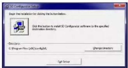
- Once enabled, the program will install in the designated file directly. When completed, a popup will appear indicating completion. Acknowledge by clicking OK. This will return the computer display to your original Windows Explorer screen.
- Verify the program loaded by selecting the Main Start Menu of the computer and locating the "5D Configurator" icon.
(cont'd)
1. INTRODUCTION
- To RUN the Configurator, go to your Windows popup Start menu, select Programs, and click 5D Configurator. The follow screen will appear

File Menu
New - Starts blank configuration
Open.... - Retrieves stored configuration
- Clears existing configurationClose
Save - Stores ".fiv" configuration file
Save as.. - Stores renamed ".fiv" file
Exit - Exit configuration program
Serial Communications Menu
Initialize Port - Selects COM port to use
Terminal - Used for direct command and response setup and queries to the 5D(s)
Upload 5D Module(s)
- Retrieves all connected module's configuration information to begin setup changes and calibration
- To UNINSTALL the 5D Configurator Software,
a. Go to the Windows popup Start menu, select Settings, and then select Control Panel. Then double-click on the button called Add/Remove... (or Add or Remove Programs).
b. Select "5D Configurator" from the list of programs, and click the appropriate button to remove it.
c. When asked whether you're sure you want to completely remove the 5D Configurator and all its components, answer Yes to uninstall (or No to abort).
d. NOTE: This procedure will NOT delete any "*.fiv" 5D CONFIGURATION FILES currently in your Configurator installation directory which were created through the Configurator software. In fact, if you have created any such files, you will be told that the directory itself cannot be removed (click Ok to exit this message).
2. CONNECTIONS
2.A INTRODUCTION
Pin assignments for the 5D40's standard DB25 POWER, CONFIGURATION, LOGIC, AND ANALOG OUTPUT CONNECTOR are shown in Fig. 3.a, below.
Fig. 3.b gives pinout for these same functions for the screw-terminal connection provided by the Models 5D40V (±10-volt output) and 5D40S ("S" Option). The only difference is that the ENABLE logic lines are not available with these modules.
Fig. 4 is a generalized diagram of a "network" of one to sixteen individual Daytronic 5D modules, including the
PC being used for module configuration and the network power supply. The proper connections required for Power and Ground, RS232 Communications, Transducer I/O, Analog Outputs, and Logic Inputs are treated separately in the sections and figures that follow.
NOTE: When a network of 5D modules is installed in a Daytronic "5DMB" backplane unit, all module interconnections are automatically established (see the Model 5DMB Instruction Manual for full details).
Fig. 3 5D Power, Configuration, Logic, and Analog Output Connections
Fig. 3.a Standard DB25 Connector (Model 5D40)
ALL PINS NOT LISTED ARE CURRENTLY UNUSED.
Pin Line Number(s) Function
1 5-V ANALOG OUTPUT A (CONTINUOUS)
2 5-V ANALOG OUTPUT B (SWITCHABLE)
3, 14 ANALOG COMMON
10 TRANSMIT (RS232 OUTPUT)
11 RECEIVE (RS232 INPUT)
12 24 VDC POWER INPUT
13 POWER COMMON
16 ENABLE (LOGIC INPUT; REFERENCED TO ANALOG COMMON)
22 ENABLE (LOGIC INPUT; REFERENCED TO POWER COMMON)
25 CHASSIS GROUND
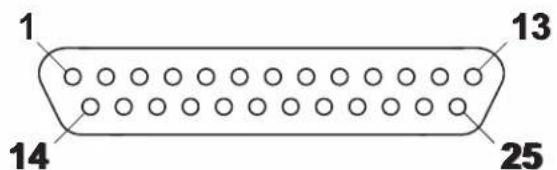
Fig. 3.b
Alternative Screw-Terminal Connection (Models 5D40V and 5D40S)

2. CONNECTIONS

flowchart
graph TD
    A["Configuration PC"] --> B["RS232 Serial Communications (see Fig. 5)"]
    B --> C["Chassis Ground*"]
    C --> D["Transducer Interconnections (see Fig. 6)"]
    D --> E["Analog Outputs (see Fig. 7)"]
    E --> F["Logic Inputs (see Fig. 8)"]
    F --> G["Power and RS232 Serial Communications (see Fig. 5)"]
    G --> H["Power and RS232 Serial Communications (see Fig. 5)"]
    H --> I["* See Section 2.B."]
    J["24 VDC POWER SUPPLY"] --> B
    style A fill:#f9f,stroke:#333
    style B fill:#ccf,stroke:#333
    style C fill:#cfc,stroke:#333
    style D fill:#fcc,stroke:#333
    style E fill:#cff,stroke:#333
    style F fill:#ffc,stroke:#333
    style G fill:#cfc,stroke:#333
    style H fill:#cfc,stroke:#333
    style I fill:#cfc,stroke:#333
2.B POWER AND GROUND CONNECTIONS
The 5D40(V) requires a user-supplied external source of 24 VDC, regulated to ±10%. Nominal consumption is 100 mA; maximum is 150 mA. Fig. 5 on the next page shows how the positive and negative power leads are tied, respectively, to the +24 VDC and POWER COMMON terminals of the 5D40's standard DB25 connector (the Models 5D40V and 5D40S use the corresponding screw-terminal connections—see Fig. 3.b).
In a network of more than one 5D module, you can power the entire chain by connecting the supply to any given module—although it is recommended that it be connected to the first one, as shown. The +24 VDC terminals of adjacent modules are then tied pin-to-pin, as shown in Fig. 5. The +24 VDC line between adjacent modules may be paired with the RECEIVE line in the cable shield (as shown), or it may be shielded separately. The cable shield is tied to POWER COMMON.
When the 5D40(V) is properly powered, the module's indicator light will be GREEN—unless there is presently an input overrange of 20% or more, an incoming CARRIAGE RETURN, or a serious hardware/software malfunction (see Section 5.A).
CABLE SHIELDING
Proper shielding of cable wires or twisted pairs—as shown in Figs. 5 through 8—is strongly recommended to minimize the production of unwanted electrical noise from capacitive and inductive effects.
In the I/O cabling diagrams (Figs. 6 through 8), only the "connector end" of each cable shield is shown, as represented by a gray circle surrounding either a single wire or a TWISTED PAIR of wires within the cable. Unless otherwise stated, every shield should be grounded to the appropriate common or ground terminal only at the connector end. The drain wire tying the connector end of the shield to common/ground should be as short as possible.
MODULE GROUNDING
For optimum ESD/EMI immunity, every 5D module should be LOCALLY GROUNDED. Use a single drain wire to connect the module's CHASSIS GROUND terminal (No. 25) to local earth ground (see Fig. 5). The drain wire should be as short as possible.
2. CONNECTIONS

flowchart
graph TD
    A["5D MODULE"] --> B["DB25 CONNECTOR"]
    B --> C["SHIELD SHIELD"]
    C --> D["5D MODULE"]
    E["TRANSMIT"] --> F["10"]
    G["RECEIVE"] --> H["11"]
    I["+24 VDC"] --> J["12"]
    K["POWER COM."] --> L["13"]
    M["CHASSIS GRND."] --> N["25"]
    O["CONFIGURATION PC"] --> P["COM PORT"]
    Q["RECEIVE"] --> R["SHIELD*"]
    S["TRANSMIT"] --> T["SHIELD*"]
    U["COMMON"] --> V["SHIELD*"]
    W["24 VDC POWER SUPPLY"] --> X["SHIELD*"]
    Y["Figure 5 5D Power / Serial Communications Connections"] --> Z["DB25 CONNECTOR"]
    AA["The following POWER SUPPLIES are available from Daytronic: Model 5DPS1 (DIN-mount, 7.5 W, for 1 module)"]
    AB["Model 5DPS3 (DIN-mount, 15 W, for up to 3 module)"]
    AC["Model 5DPS6 (DIN-mount, 30 W, for up to 6 module)"]
    AD["Model 5DPS10 (DIN-mount, 50 W, for up to 10 mod)"]
    AE["Model 5DPS16 (DIN-mount, 100 W, for up to 16 mod)"]
    AF["Model 5DPW4 (wall-mount, 18 W, for up to 4 module)"]
    AG["The following SINGLE-MODULE CONNECTOR ASSEMBL is available from Daytronic: Model 5DMC1 (25-to-9-pin adaptor with screw-term)"]
    AH["The following COMPUTER INTERFACE CABLES are available from Daytronic: Model 5DIC232 (DB9-to-DB9, for use with 5DMC1 and "5DMB" motherboards)"]
    AI["Model 5DSIC232 (Screw-Terminal-to-DB9, for use with 5D Series "V" and "S" models)"]
2.C SERIAL COMMUNICATIONS CONNECTIONS
As shown in Fig. 5, simple two-wire RS232 cabling is employed for communications between the 5D40(V) module and an external PC.* The RS232 interface observes a fixed protocol of 19,200 baud, 8 data bits, 1 stop bit, and NO parity—with no software or hardware "handshake." The Configurator software will automatically set to this protocol the computer COM PORT selected for communications with the 5D network.
Separate shielding of the RECEIVE and TRANSMIT lines is highly recommended, to prevent electrical noise from causing "break" signals and other communications errors. If desired, the RECEIVE line may be paired with the +24 VDC line in the cable shield (as shown). The cable shield is tied to POWER COMMON. Separate RECEIVE and TRANSMIT shielding is also recommend-
ed for the cable connecting the 5D module to the PC COM PORT, if that cable is over 3 feet in length.
As with power connections (above), you can establish communications with all members of a network of more than one 5D module by connecting the PC COM PORT to any given module—although it is recommended that it be connected to the first one, as shown.** The RECEIVE and TRANSMIT terminals of adjacent modules are then tied pin-to-pin, as shown in Fig. 5.
* For corresponding screw-terminals of the Models 5D40V and 5D40S, see Fig. 3.b.
While 5D / PC serial communications will usually take place through the 5D CONFIGURATOR software described in Section 3, a "terminal emulation" program (either conventional or customized) can also be used to issue standard mnemonic commands to one or more 5D modules, and to receive module responses.
** Unless you are using the 5D Configurator software, it is first necessary to issue an OPEN (OPN) command in order to initiate single-point communications between the computer issuing the command and a specific 5D module (see Section 4.A).
2. CONNECTIONS
2.D TRANSDUCER CONNECTIONS
Each wire or jumper of the transducer cable is to be firmly secured to the appropriate screw terminal of the terminal block that plugs into the 5D40(V)'s 10-pin TRANSDUCER CONNECTOR.
As shown in Figs. 6.a and 6.b, below, the Model 5D40(V)'s differential inputs (+SIGNAL and -SIGNAL) are normally used when connecting the module to a magnetic pickup for conventional tachometric applications. When the ±SIGNAL lines are used for direct sensor connections, note that
- The TTL SIGNAL input (Terminal 7) must be tied to -EXCITATION (Terminal 6).
- It is strongly recommended that the -SIGNAL line be tied to the module's 0.1 μF COUPLING terminal (as shown in Figs. 6.a and 6.b). This serves to suppress unwanted signal noise, especially at the low-frequency input range.*
Fig. 6.a gives the wiring for a pickup connection via shielded twisted-pair cable, while Fig. 6.b gives the wiring for a pickup connection via coaxial cable. With coaxial cabling, the shield connection is not required, and the -SIGNAL line should be tied to EXCITATION COMMON (Terminal 10), which then connects directly to the sensor (as shown).
The Model 5D40(V)'s TTL input should be used when connecting the module to any generic TTL device (Fig.
6.c) or to a "zero-velocity" (true digital output) sensor requiring 5-V excitation (Fig. 6.d). When the TTL SIGNAL is directly connected to the sensor, the +SIGNAL and -SIGNAL inputs must be tied to EXCITATION COMMON (Terminal 10) and -EXCITATION (Terminal 6), respectively.
ALSO NOTE: The general TTL connections shown in Fig. 6.c should always be used when the input frequency is greater than 200 KHz or less than 2 Hz.
An additional wire is shown in Fig. 6.d connecting the zero-velocity sensor's -EXCITATION pin and the 5D40(V)'s EXCITATION COMMON (Terminal 10). This wire is recommended when the cable resistance is greater than 20 ohms. When used, the additional wire and the +EXCITATION line should make a separate shielded twisted pair, as shown. The +SIGNAL and main -EXCITATION lines should always be paired and shielded.
For general information on CABLE SHIELDING, see Section 2.B.
* The larger 10 μF COUPLING (Terminal 4) is for removal of relatively large amounts of ± DC offset, and is not normally required. Contact the factory for connection details.
Fig. 6
Model 5D40(V)
Transducer Connections
Fig. 6.a Input from Magnetic Pickup, Using Twisted-Pair Cable
![MAGNETIC PICKUP SHIELDED TWISTED PAIR SCREW TERMINAL BLOCK PLUGGED INTO TRANSDUCER CONNECTOR 10 10 9 8 8 7 6 5 4 3 2 1 5D40(V) EXC. COMMON +SIGNAL -SIGNAL TTL SIGNAL -EXCITATION 0.10 µF COUPLING 10 µF COUPLING +EXCITATION [FOR FUTURE USE] SHIELD* *(NOT ISOLATED; connects internally to CHASSIS GROUND)](/content/2026/05/1077520/images/5af554b39724066fa6eb35d069acdf3ec3705c2fd1ff57293703690b8712161a.jpg)
2. CONNECTIONS
Fig. 6.b Input from Magnetic Pickup, Using Coaxial Cable
![MAGNETIC PICKUP COAXIAL CABLE SCREW TERMINAL BLOCK PLUGGED INTO TRANSDUCER CONNECTOR 10 10 9 8 7 6 5 4 3 2 1 5D40(V) EXC. COMMON +SIGNAL -SIGNAL TTL SIGNAL -EXCITATION 0.10 µF COUPLING 10 µF COUPLING +EXCITATION [FOR FUTURE USE] SHIELD](/content/2026/05/1077520/images/290dfa533af0d7b599f3591fe00b7f1a8537f2a5f86148d0b19db0749727ecaf.jpg)
Fig. 6.c Input from Generic TTL Device
![SCREW TERMINAL BLOCK PLUGGED INTO TRANSDUCER CONNECTOR TTL DEVICE SIGNAL COMMON SHIELDED TWISTED PAIR (NOT ISOLATED; connects internally to CHASSIS GROUND) 5D40(V) 10 10 9 8 7 6 5 4 3 2 1 EXC. COMMON +SIGNAL -SIGNAL TTL SIGNAL -EXCITATION 0.10 µF COUPLING 10 µF COUPLING +EXCITATION [FOR FUTURE USE] SHIELD*](/content/2026/05/1077520/images/2916bba77268b3ec1a274ab0f01538b4f585d9fd9483b3a999e27b1f73969fa5.jpg)
1. INTRODUCTION
Fig. 6.d Input from Zero-Velocity Sensor with 5-Volt Excitation

flowchart
graph TD
    A["ZERO-VELOCITY SENSOR"] --> B["SHIELDED TWISTED PAIR"]
    B --> C["Recommended for cable resistance > 20 ohms"]
    C --> D["+SIGNAL"]
    C --> E["+EXCITATION"]
    D --> F["SCREW TERMINAL BLOCK PLUGGED INTO TRANSDUCER CONNECTOR"]
    E --> F
    F --> G["10 V 5D40 exc. common + signal - signal TTL signal - excitation 0.10 μF coupling 10 μF coupling + excitation FOR future use SHIELD*"]
    style A fill:#f9f,stroke:#333
    style G fill:#ccf,stroke:#333
Fig. 6.e
Input from General Frequency Source
![COAXIAL CABLE FREQUENCY SOURCE SCREW TERMINAL BLOCK PLUGGED INTO TRANSDUCER CONNECTOR 10 10 9 8 7 6 5 4 3 2 1 5D40(V) EXC. COMMON +SIGNAL -SIGNAL TTL SIGNAL -EXCITATION 0.10 μF COUPLING 10 μF COUPLING +EXCITATION [FOR FUTURE USE] SHIELD](/content/2026/05/1077520/images/9888deb91931ef228cef136466b8c333f9a8801f92acfcf0f1078d5efe901ebb.jpg)
2. CONNECTIONS
2.E ANALOG OUTPUT CONNECTIONS
Fig. 7 shows how an A/D Card, datalogger, recorder, or other external device connects to one of the Model 5D40's two 5-V ANALOG OUTPUTS, using the standard DB25 connector shown in Fig. 3.a.* The 5D40V's two 10-V outputs and the 5D40S's two 5-V outputs are similarly connected, using the corresponding screw terminals shown in Fig. 3.b. Each output is single-ended, and returns to ANALOG COMMON. The cable shield should also be tied to ANALOG COMMON.
* Outputs A and B are independently filtered. For the standard Model 5D40, Output A is continuously available, while Output B may be switched on and off via the logic "ENABLE" line (see Section 2.F, below). For the Models 5D40V and 5D40S ("S" Option), the "ENABLE" function is not provided, and both analog outputs are continuously available.
NOTE: When a network of 5D modules is installed in a Daytronic "5DMB" backplane unit, each module's Analog Output A is accessible from a terminal block on the board (Output B is also available when the eight-module Model 5DMB-8 is used; see the the Model 5DMB Instruction Manual for full details).
Fig. 7
5D Analog Output Connections

flowchart
graph LR
    A["ANALOG OUTPUT A"] --> B["ANALOG OUTPUT B *"]
    B --> C["ANALOG COMMON"]
    D["CHASSIS GRND."] --> E["DB25 CONNECTOR"]
    E --> F["SHIELD"]
    F --> G["EXTERNAL DEVICE"]
    G --> H["+"]
    G --> I["-"]
    F --> J["EXTERNAL DEVICE"]
* Active when "Enable" is at LOGIC 1, which is the default state (i.e., in the absence of any connection to the ENABLE input terminal). See Fig. 8.
2. CONNECTIONS
2.F LOGIC INPUT CONNECTION
The standard DB25 connector of the Model 5D40 (shown in Fig. 3.a) has a terminal for a single "positive-true" logic-level input (not available on the screw-terminal connector of the Model 5D40V or Model 5D40S (Fig. 3.b))*:
- ENABLE — used to switch the module's ANALOG OUTPUT B**
Fig. 8.a shows how this command input can be applied to a 5D40's DB25 connector, without the need of an external logic reference supply. You may also use active TTL logic, as illustrated in Fig. 8.b, to produce the "ENABLE ANALOG OUTPUT B" condition for the 5D40.
* For this input, the Logic 1 state is represented by nominal 5 VDC, and is the "true" state (indicated by the name of the input); the Logic 0 state is represented by nominal 0 VDC, and is the "false" state. Thus, when the "Enable" input is at Logic 1, Analog Output B is enabled. The logic input may be generated directly from dry contacts (switches, relays, etc.), as in Fig. 8.a, or from solid-state logic systems, as in Fig. 8.b. It will assume the Logic 1 state in the absence of any connection.
** If the logic signal for control of a Model 5D40's Analog Output B is referred to the same common as the analog outputs (i.e., ANALOG COMMON), Terminal No. 16 is available for connection of that signal. Note too that a logic input connected to Terminal No. 22 (only) may also be used in the Initialization routine of certain Daytronic "5DMB" backplane units (see the Model 5DMB Instruction Manual and the description of the MODULE IDENTIFICATION (MID) command in Appendix A).
Since "ENABLE" is not provided for the Models 5D40V and 5D40S, both analog outputs are continuously available for these modules.
Fig. 8
Model 5D40 Logic Input Connection
Fig. 8.a Switch Closure, No External Supply

Fig. 8.b Active TTL Logic

3. CONFIGURATION AND CALIBRATION
3.A USING THE 5D CONFIGURATOR
WHAT IS THE 5D CONFIGURATOR?
Employing the 5D Configurator software lets you define, store, edit, download, upload, and manage any number of "configurations" for a connected array of one to sixteen independent Daytronic "5D" Signal Conditioner Modules.
Every "5D configuration" actually consists of a numbered set of individual module configurations (or "setups"), one for each module in the connected network, along with general information pertaining to the complete collection of individual module setups.
Every real-world application of a particular 5D module requires its own unique configuration. A module "configuration" is a set of operating parameters that instruct the signal conditioner precisely how it is to process sensor-based measurement data. The information contained in a 5D module configuration includes module-specific setup parameters and calibration data.
Specifically, the 5D Configurator lets you
- set up and test serial communications between the PC running the Configurator software and each and every connected 5D module
- enter identifying and descriptive information for each connected 5D module, tag name, engineering units, optional description strings, and optional transducer model/serial number
- define module-specific setup values, including each module's analog filter cutoff frequencies.
- define or view general parameters relating to the entire set of individual module configurations, including file path and size, configuration description, calibration info., comments, etc.
• perform selected run-time operations, including
— both "absolute" and two-point (deadweight) calibration of a specific module
— sending one or more standard mnemonic commands to a specific module
— applying a positive or negative calibration shunt to a specific DC Strain Gage Module
- download an individual module configuration to a specific module
- download an entire 5D configuration to a network of modules
- upload the current configuration(s) of all connected modules to a new configuration file, for storage and/or editing
- upload an individual module configuration (to be appended to the presently open configuration file)
- "update" an existing module configuration based on the active setup values of the corresponding connected module
STARTING THE 5D CONFIGURATOR
Instructions for installing and running the Configurator software were given in Section 1.C.
After the Configurator starts up, you can do one of three things:
- OPEN AN EXISTING 5D CONFIGURATION by selecting Open... from the File menu
- CREATE A NEW 5D CONFIGURATION by selecting New... from the File menu
- UPLOAD A 5D CONFIGURATION by polling the connected module array to a New Configuration using the Serial Communications entry tab.
An overview of the procedure for creating a new module configuration via the New... command is given in Section 3.C, below.
FILE MENU
New...
Select to create a new configuration
Open...
Select to open an existing configuration
Close
Select to close the open configuration
Save
Select to close the open configuration
Save As...
Select to save the open configuration using a new file name
Exit
Select to exit the Configurator program
3. CONFIGURATION AND CALIBRATION
3.B SUMMARY OF CONFIGURATOR MENUS
SERIAL COMMUNICATION MENU
Initialize Port
Selects the computer's communication port to be utilized - Com Port Definition
Terminal
Sends direct command and response syntax statements to the 5D modules. See section A.2
Upload 5D Module(s)
When selected, will upload all connected 5D modules.... up to 16 modules can be uploaded using the 5D configurator software.
In general, you will take the steps listed below to develop a new configuration for an array of one to sixteen connected 5D Signal Conditioner Modules (although the exact sequence of steps may vary, depending on your own preference). Alternatively, you may initially wish to upload the existing configuration of each connected 5D module to form a new 5D configuration, which you may then proceed to modify as desired. In this case, you need not perform the "To Create a New 5D configuration" as listed in section 3.C
The numbering of individual modules within a total 5D configuration is initially determined by the order in which they have been sequentially added to that configuration, or by the order of the list of serial numbers used by the Configurator to upload one or more individual configurations from the connected module array. Thus, any given Module Number within a total configuration need not necessarily reflect the physical placement of that module on the external 5D network. You can always rearrange the sequence of module setups so that they do in fact correspond to the external module arrangement. Modules can also be added or removed from the open configuration, as desired.
The Module Setup Parameters page displays in tabular form the most important setup parameters for all currently defined modules.
Once a given 5D module's setup configuration (Fig 5) has been completely entered (including all required calibration information), it may then be individually downloaded to that module. Or the entire "5D configuration" may be downloaded to the connected network, in which case each individual module setup within the collective configuration will be downloaded to its respective module.
HOME PAGE - SERIAL COMMUNICATIONS TAB

Fig. 1
NEW CONFIGURATION PAGE w/ default modules
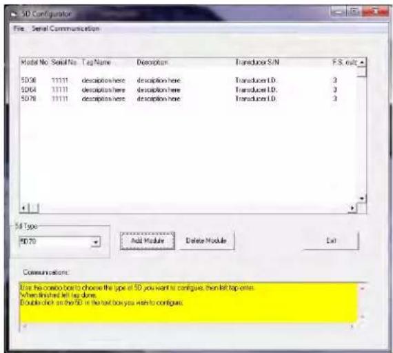
Fig. 2
3. CONFIGURATION AND CALIBRATION
3.C OVERVIEW OF THE CONFIGURATION PROCESS
To Create a New 5D configuration - OFF LINE
- Using the New... menu command, open to a new (blank) configuration. A list of all available 5D Series Conditioner Modules appear in the pull down selection box on the left side of the menu. Select the Module type that you wish to add to the configuration. Click the Add Module button on the Module Setup page (Fig 2) to add the first module to the configuration. Continue to add module types as needed. Once completed, double click on the first Module Model No. in the worksheet area to begin configuration.
- With the first Module selected, the Module Type Absolute Menu page (Fig 3) will be displayed allowing the user to configure the specific module's parameters as needed. Once the specific module parameters are entered, Click on the "Next 5D" to sequence to the next module in your configuration. Enter the specific parameters and continue through the complete configuration. When completed "Exit" the Absolute Configuration Page and save to file.
- When the "New" configuration is downloaded to a connected 5D array, the program will query the modules and allow for proper serial number assignment and configuration. Each module configuration will be assigned it unique serial number, replacing the "11111" default ID. Save the configuration as needed on "Exit" of the Summary Configuration Page (Fig 4) or proceed to the "two point" calibration process for each module as describe in 3.D.
To Upload a connected 5D configuration - ON LINE
- Using the Upload 5D Module(s)... command. Under the "Serial Communications" tab on the Home page. Click on the "serial communications" tab and click on the "Upload 5D modules" tab. Selecting this tab will initiate an uploading of the connected 5D modules configuration setups. Once completed the specific parameters are displayed on the Summary workspace screen. Double click on the specific module to review or change. Through the Model Type Absolute Menu page the user can access the "two point" or "dead-weight" calibration of the specific module.
- The Module Type Absolute Menu Page is used to review, alter or process through the Module's parameters for a specific 5D that was uploaded, or created as "new". It is called "absolute" due to the module's calibration parameters being entered with known documented values such as sensitivity, full scale value, zero offset, expected load, etc. - which are downloaded to the module prior to a "two point" calibration verification. Menu through the parameters to configure the module for the application. Once a field value has been changed, the "Download" button will be enabled to allow the configuration to be sent the specific 5D module. Note when completed the "Calculated Parameters" (which is the result of the entered menu values) will be the same as the "Current Parameters" (which are the values stored into the 5D module).
ABSOLUTE CONFIGURATION PAGE w/ default module

Fig. 3
SUMMARY CONFIGURATION PAGE w/ uploaded modules

Fig. 4
ABSOLUTE CONFIGURATION PAGE w/ uploaded module

Fig. 5
3. CONFIGURATION AND CALIBRATION
ABSOLUTE CONFIGURATION PAGE parameter information
Changable user parameters -
Description - User entered description (up to 32 characters) scratch pad field for general module information
Tag Name - Short name field (16 characters) for ID information.
Transducer Model / Serial Number - User information for tracable connection of module to the sensor
Engineering Units - User information field for transducer measurement value
Transducer Rated Full Scale Load - Specification information of the transducer's rated capacity. Affects gain calculation.
Maximum Expected Transducer Load - Application information of the transducer's working capacity. Optimizes gain level.
Transducer sensitivity - Entery of the transducer's electrical characteristic, typically obtain from calibration document of the sensor
Zero Offset Compensation 5D Input - Select Offset value in Engineering Units or is Electrical Units
Tracking Window Width - Enables cycle to cycle average tracking width of the frequency input
Offset value - Zero offset of the sensor (range is +/- 20% of full scale value)
Full Scale Negative Transducer Input - Used to calculate the symmetry compensation value level.
Excitation Frequency or Level - Module specific parameter for power to the sensor connected to the module.
"A" Output Analog Filter - Selects 3 db corner response on the analog output signal
"B" Output Analog Filter - Selects 3 db corner response on the analog output signal
Information parameters -
Module Type - 5D Module Model Identification
5D Maximum Output - Identifies the module's full scale output level.... 5V or 10V unit.
Serial Number - ID number of the Module used to address the unit for upload-download parameters
Download - WIII initiate downloading of configuration parameters to the identified module
Cancel Changes - Clears changes to the module's calculated parameters
Exit- Returns user to Summary page or queries for a "save configuration" if needed.
Save - Queries user for file information to save the configuration.
Two Point Calibration - When enable via changes, will enter into the "Two-Point" menu page for on-line calibration process
Next 5D - Sequences to the next active 5D module in the current configuration
Last 5D - Sequences to the last active 5D module in the current configuration
Calculated Parameters - Absolute calibration calculated command parameters to be sent to the module for update Current
Parameters - Actual command parameters that are present in the module which affect calibration.
Date Last Calibrated - Recorded date of last calibration of the module.
3. CONFIGURATION AND CALIBRATION
CALIBRATION OVERVIEW
To calibrate a 5D40(V), the first step is to enter the User Configured parameters within the Absolute Menu Page as decribed in section 3.C. Specific parameters which affect calibration are:
- Maximum Expected Frequency Input
- Offset value (Zero)
-
Input signal sensitivity
-
Once the Absloute Calibration information has been downloaded to the specific module. The "Two Point" button will be enabled. Once the download is complete, Click on the "Two Point" button. Once this action has been acknowledged, the "Two Point" page will be displayed.
-
Two Point calibration is used to "fine" tune the analog output of the module to reflect the actual values specific to the sensor's input to the module. Sometimes referred to as "dead weight calibration"; where the input is stimulated via a known voltage value or sensor output calibration value
-
With the analog output for the specific module under calibration - being measured (recommend a 5 digit voltmeter or similar device), begin the two point process by measuring the analog output of the Module at "Zero" sensor input. Click on the "Start Calibration" button. This will hi-light the "Zero Calibration" area. Select the "Count by" value needed for the adjustment. With a known Zero value, increment or decrement the Zero Calibration field to achieve the expected Zero analog output result. Range adjustment for Zero is +/-20.00% of full scale. Note when changing this value, it is done on-line with the module and a short delay will occur between the program action and the response of the analog output result.
-
Once the "Zero" parameter has been established, Click "Continue" to proceed to the "Span Calibration Point". This field is used to adjust for any Gain or Span changes needed. With a known frequency or sensor input, increment or decrement the Span Calibration value for the appropriate analog output value. Typically this is done at the nominal working level of the sensor, which may or may not be full scale.
-
Click "Continue" to proceed to the Linearity adjustment. The 5D40(V) module has mid-scale analog correction to compensate for any linearity errors at the mid-range area of the sensor input. If needed, Load the sensor or provide a known frequency value to its positive mid-point full scale value and increment or decrement the value (+/- 2.00 %) to provide correction to the positive analog output value.
TWO POINT CALIBRATION PAGE
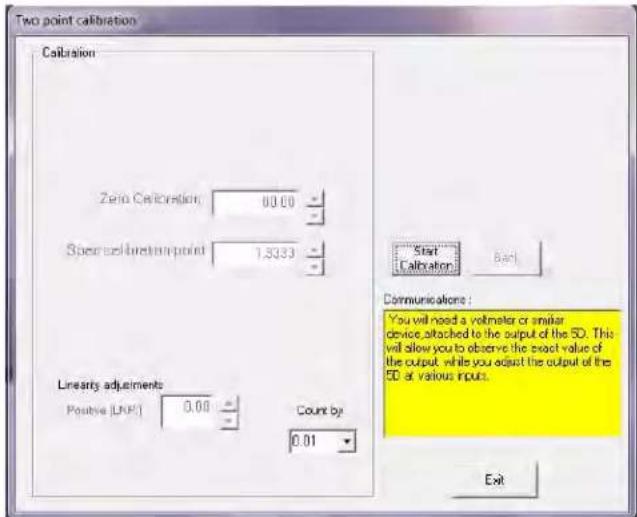
- When completed, Click on the "Continue" button until it is no longer hi-lighted. Click on "Exit" to save the changes to the module. When completed downloading - a menu to save the new configuration file will appear. Once completed the Absolute Calibration Page will display overviewing the calibrated module.
* Note: Due to analog adjustment of the module, step 3 & 4 should be re-checked. Gain adjustment will affect the "zero" setting. Utilize the "Back" button for this purpose.
3. CONFIGURATION AND CALIBRATION
Midscale Linearity Correction
The Configurator's LINEARITY POSITIVE (LNP) field is for entry of a midscale linearity correction in the positive domain. The linearity improvement furnished here is useful in cases where the output linearity error increases and decreases smoothly (with no inflections) with increasing values of input.
You may wish to determine through standard error-plot analysis the approximate correction that needs to be applied to the output midway between zero and full scale, as a plus or minus percent of the actual output reading at that point (it cannot exceed ±2.00% of mid-
scale output). You would then enter this number directly in the LNP field, after which you should observe the actual midscale output reading to see if further adjustment is necessary (if so, you may use the corresponding UP / DOWN ARROW buttons). Fig. 10, below, illustrates a typical nonlinearity in need of positive mid-scale correction.
NOTE: A positive LNP value moves the positive-domain midpoint upwards (yielding a larger positive reading at that point), while a negative LNP value moves it downwards (yielding a smaller positive reading).
Fig. 10 Linearity Correction in the Positive Domain

line
| Midpoint (50% of full scale, Positive) | Actual (Uncorrected) Midscale Output | Uncorrected "Nonlinear" Output | Ideal "Linear" Output | | -------------------------------------- | ------------------------------------- | ------------------------------ | --------------------- | | y_d | y_d | y_d | y_d | | Δy | Δy | Δy | Δy |To correct for positive-directed non-linearity in the positive domain, enter a POSITIVE LINEARITY (LNP) command of
$$ \mathrm{LNP} = - (\Delta \mathrm{y} / \mathrm{y} _ {\mathrm{d}} * 1 0 0) $$
A negative LNP value is entered because the midpoint of the actual output curve needs to be pushed downward (in the negative direction).
NOTE: For purposes of illustration, the magnitude of nonlinear deviation ( y ) has been exaggerated in this figure.
4. OPERATING CONSIDERATIONS
4.A SENDING A COMMAND TO THE 5D40(V)
The 5D Configurator software lets you send standard mnemonic commands to a specific connected 5D module, one command at a time, while viewing the module's exact response to each command as it is sent. This feature can be used not only to perform run-time adjustments to the module setup, but also to review the module's current configuration status and to issue run-time "imperative" commands as desired.
For use of the Configurator's Terminal... window, see page 3.2 in the 5D Configurator Home Page
* When using a terminal program (such as Windows HyperTerminal), remember that every 5D module's RS232 communications interface employs a fixed protocol of 19,200 baud, 8 data bits, 1 stop bit, and No parity—with no software or hardware "hand-shake."
**The QUERY MODULE ID (QID) command may be used to obtain the serial number of each 5D module in a connected array, without having to "open" any specific module(s). See the description of QID in Appendix A.
A “terminal emulation” program (either conventional or customized) can also be used to issue standard mnemonic commands to one or more 5D modules, and to receive module responses.*
When using a terminal program, it is first necessary to issue an OPEN (OPN) command of the form
OPN=xxxx [CR]
* Note: OPN command is Case sensitive
in order to initiate single-point communications between the computer issuing the command and the single 5D module bearing SERIAL NUMBER "xxxx." The addressed module (only) will respond to a valid OPN command with "ACK."**
When a given 5D module is "open" for RS232 communications, its indicator light will flash (see Section 5.A).
For a discussion of 5D Series command and response syntax, plus a description of all 5D setup, interrogation, and imperative commands, see Appendix A.
5. TROUBLESHOOTING
5.A INTERPRETING THE STATUS INDICATOR LIGHT
Shown in Fig. 1, the 5D40(V)'s status indicator light serves to monitor the module's power, input, communications, and general health condition. The condition(s) represented by the light's three possible colors and color combinations are given below.
If the indicator light is flashing a single color, or is alternating between YELLOW and GREEN, it means that the module is currently "open" for RS232 communications (see Section 4.A, above). If the indicator is alternating between RED and GREEN, the module may or may not be "open." Obviously, if the indicator is lit with any color or color combination, it indicates that power is ON.
GREEN
Input signal is OK
YELLOW
Input signal is over 20% out of range
* This need not be a syntactically valid command (see Appendix A); it could, in fact, be any ASCII string terminated by a carriage return.
RED
Serious input condition detected (e.g., excessive current, overvoltage); could indicate transducer short or faulty cabling
YELLOW / GREEN
The module has received a mnemonic command* through its RS232 port (the yellow light will continue for about a second after receipt of the command-terminating carriage return)
RED / GREEN
Significant internal software error detected; contact the Daytronic Service Department
5.B INTERPRETING THE MODULE DIAGNOSTIC CODE
The last four characters of a 5D module's response to a MODULE IDENTIFICATION (MID) interrogation will always represent the module's current ERROR (or DIAGNOSTIC) CODE. Intended primarily as a programming tool, this code will help identify the nature of syntax and communications errors when they occur (when, for example, the computer receives a response of "NAK" instead of an expected "ACK").*
The first of the four code characters is an alphanumeric character (0 through 9, A through J, or Z). The next three characters are hexadecimal digits (0 through 9, A through F). Note that syntax and communication errors will combine additively to generate the respective digit. For example, a combination of serial communication errors "4" and "8" will yield a fourth character of "c" (= decimal 12).
* After a mnemonic command has been sent to a given 5D module via the Configurator's Send Command... window (see Section 4.A), the module will be immediately and automatically queried for its current diagnostic code. The response will be displayed in the lower right-hand corner of the window. If an erroneous command has been sent, the code will help identify the precise nature of the error.
The diagnostic code characters (X_1, X_2, X_3, X_4) are as follows:
FIRST CHARACTER ( X_1 )
Indicates the three-letter MNEMONIC CODE of the previously received command:
| X_1 | MNEMONIC X | 1 | MNEMONIC |
| 0 [NONE] C RNG | |||
| 1 AFL | D RSM | ||
| 2 EXC | E | SEN | |
| 3 EXF | F SHN | ||
| 4 FAZ | G | SHP | |
| 5 MID | H SHS | ||
| 6 MIO | J | SYM | |
| 7 MOO | P | LNP | |
| 8 MP_ | N | LNN | |
| 9 MSF | R | TWW | |
| A | OPN | Z | UNKNOWN |
| B | QID | ||
| (cont'd) | |||
5. TROUBLESHOOTING
SECOND CHARACTER (X_2)
Indicates SYNTAX OR VALUE error:
| X_2 | Error | |||
| 0 | N | O | N | E |
1 Syntax Error
2 Numeric Range Error
4 [NOT USED]
8 [NOT USED]
THIRD CHARACTER ( X_3 )
Indicates OTHER COMMUNICATION error:
| X_3 | Error | ||||
| 0 | N | O | N | E | |
1 Unknown Mnemonic
2 Illegal Character in Mnemonic Field
4 [NOT USED]
8 [NOT USED]
FOURTH CHARACTER ( X_4 )
Indicates SERIAL COMMUNICATION error:
| X_4 | Error |
| 0 | N | O | N | E |
1 Break, UART Framing or Overrun Error
2 Receive Buffer Overrun
4 Insufficient Characters for Command
8 Received Before ACK/NAK (i.e., before a previous command had been answered)
SUMMARY OF 5D40(V) MNEMONIC COMMANDS
PLEASE NOTE: This appendix treats only those 5D Series mnemonic commands that are applicable to the Model 5D40 or 5D40V Frequency Conditioner. Valid commands that only apply to other 5D models (and NOT to the 5D40(V)) will evoke a response of NAK when issued to a 5D40(V) module.
A.1 COMMAND AND RESPONSE SYNTAX
When issuing one or more commands to a 5D module by some means other than the 5D CONFIGURATOR software, please note the following:
- You must apply the OPEN (OPN) command to establish RS-232 communications with that module, as explained in Section 4.A ("Sending a Command to the 5D40(V)"). The QUERY MODULE ID (QID) command may be used to obtain the serial number of every connected module, prior to application of the OPN command to any specific module.
- SPACE CHARACTERS SHOULD NOT BE INCLUDED IN ANY COMMAND EXPRESSION.*
- ALL COMMANDS ISSUED TO A 5D MODULE ARE TO BE TERMINATED BY A SINGLE CARRIAGE RETURN ([CR]).** ALL RESPONSES BY THE 5D MODULE ARE ALSO TERMINATED BY A CARRIAGE RETURN ([CR]). This standard termination is not shown in the specific commands and responses listed below.
- After a command has been issued, no further characters should be sent until receipt of a response to that command (ACK, NAK, or ANSWER), or until at least 0.25 second has elapsed without response (indicating that no module is currently "open").
A setup (or "write") command instructs the module to store a particular setup value in EEPROM memory, and has the general form
[MNEMONIC]=[value][CR]
* The only exception to this rule are the following MODULE PARAMETER ("MP") commands: MP0, MP1, MP2, MP3, MP4, MP5, MP8, and MP9. Spaces may be included in the character string being entered via the "write" form of any of these commands (the MP6, MP7, MPA, MPB, MPC, and MPD commands should never include spaces). See below for the allowed syntax of each "MP" command.
** Commands are never to be terminated by CARRIAGE RETURN, LINE FEED ([CR][LF]).
Upon receipt of a setup command, the module will issue a response of either "ACKNOWLEDGED" or "NOT ACKNOWLEDGED"—i.e., of either
ACK[CR] or NAK[CR]
NOTE: The ACK[CR] message will be issued only after the received setup value has been successfully stored in the 5D module's EEPROM memory.
A response of NAK[CR] means that the module did not recognize the received ASCII string as a valid mnemonic command. If, for example, you were to issue a command of RNG=6[CR], you would receive a response of NAK[CR] because there is a space following the equals sign (for space inclusion, see above); if you issued a command of LMP=0.05[CR], you would receive NAK[CR] because there is no "LMP" command; if you issued a command of LNP=+0.05[CR], you would receive NAK[CR] because the module does not recognize a plus sign in the LNP command.
An interrogation (or "read") command normally asks the module for the current value of a stored setup parameter, and has the general form
[MNEMONIC][CR]
Upon receipt of a valid interrogation command, the module will issue a response of
[value][CR]
If the interrogation command is invalid, the only response will be NAK[CR].
An imperative command does not store or request information, but rather tells the module to do something (for example, OPN=xxxx[CR] opens single-point communications with the module of serial number "xxxx"). The general form of an imperative command will usually resemble that of an interrogation command, being usually a single three-character mnemonic, although—as in the case of OPN—it can sometimes resemble a setup command. Upon receipt of an imperative command, the module will issue a response of either
APPENDIX A: 5D40(V) COMMANDS
ACK[CR] or NAK[CR], depending on whether or not the command has been recognized as valid.
NOTE: The ACK[CR] message will be issued only after the action specified by the imperative command has been successfully performed.
A.2 5D40(V) SETUP AND INTERROGATION COMMANDS
AFL ANALOG FILTER
AFL=f_A,f_B
Sets the analog output filter constant for the module's Output A (continuous output) to the number f_A (1 through 5) and for Output B (switched output for 5D40; continuous for 5D40V) to the number f_B (1 through 5). Actual cutoff frequencies corresponding to filter constants are module-specific; for the Model 5D40(V), they are as follows:
$$ f _ {A} / f _ {B} = 1: 0. 2 \mathrm{Hz} $$
$$ f _ {A} / f _ {B} = 2: 2 \mathrm{Hz} $$
$$ f _ {A} / f _ {B} = 3: 2 0 \mathrm{Hz} $$
$$ f _ {A} / f _ {B} = 4: 2 0 0 \mathrm{Hz} $$
$$ f _ {A} / f _ {B} = 5: 2 0 0 0 \mathrm{Hz} $$
Note that if a low filter setting (0.2, 2, or 20 Hz) is selected for BOTH f_A and f_B , the settings must be the same.
AFL Reads current filter-constant values; returns f_A, f_B .
LNP POSITIVE LINEARITY
LNP=m Sets the module's positive linearity adjustment to the value m (% of actual midscale output reading), where -2 ≤ m ≤ 2. Apositive LNP value moves the positive-domain midpoint upwards (yielding a larger positive reading at that point), while a negative LNP value moves it downwards (yielding a smaller positive reading). NOTE: The LNP value must be expressed in the format of X.XX (%), with or without minus sign (e.g., LNP=0.00, LNP=1.40, and LNP=-0.60 are acceptable; LNP=0 and LNP=+0.60 are not).
LNP Reads current positive linearity adjustment value; returns m.
MID MODULE IDENTIFICATION
MID Reads the module's current ID and diagnostic information string. Returns 5Dnn,xxxx,hhhh (where "5Dnn" is the Model Number, "xxxx" is the 4-charac-
ter alphanumeric Serial Number, and "hhhh" is the 4-character hexadecimal-ASCII ERROR CODE—see Section 5.B).
NOTE: There is no "write" form of the MID command.
ALSO NOTE: When the MID command is issued within 5 seconds of powerup to a module with the "ENABLE" line at the Logic 1 state, a MID response will be returned even though that module has not been specifically "opened" by means of the OPEN (OPN) command (see below). This feature is used in the initialization routine of certain Daytronic "5DMB" motherboard backplane units, where the installed modules are sequentially enabled in order to determine their respective connector "locations" (as well as their respective model and serial numbers)—see the Model 5DMB Instruction Manual. Unless you are sure that no more than one 5D module of the connected network is presently "enabled," do not issue a MID command within 5 seconds of network powerup.
MOO MODULE OUTPUT OFFSET
MOO=m
Sets the post-amplified (analog output) offset to the value m (% of full-scale output), where -20 ≤ m ≤ 20 . NOTE: The MOO value must be expressed in the format of XX.XX (% of full-scale output), with or without minus sign (e.g., MOO=01.33 and MOO=-14.50 are acceptable; MOO=1.33, MOO=-14.5, and MOO=+14.50 are not).
MOO
Reads current module output offset value; returns m.
(cont'd)
APPENDIX A: 5D40(V) COMMANDS
MP1 through MPD MODULE PARAMETER
Used by the 5D CONFIGURATOR software to write and read miscellaneous module configuration information, as follows (each MPn string \$ can have up to 16 ASCII characters; spaces may be included as desired or required in all but the MP6, MP7, MPA, MPB, MPC, and MPD strings):
MP0=\\ = Module Tag Name
NOTE: Do not enter more than eight (8) characters for the tag name; no more than eight characters will be uploaded by the 5D Configurator software.
MP1=\\ = Module Description (first 16 characters)
NOTE: The MP1, MP2, and/or MP3 string may be NULL (no characters), if desired.
MP2=\\ = Module Description (next 16 characters)
MP3=\\ = Module Description (final 16 characters)
MP4=\\ = Last Download Date/Time
NOTE: The 5D Configurator software requires an MP4 format of "(M)M/(D)D/YY (H)H:MM A" or "(M)M/(D)D/YY (H)H:MM P," depending on whether the time is "AM" or "PM," respectively; digits in parentheses are optional
MP5=\\ = Engineering Units
NOTE: The MP5 string may be NULL (no characters), if desired.
MP6=\\ = CAL1,CAL2
NOTE: The 5D Configurator software requires an MP6 format of "[number],[number]."
MP7=\\ = CAL3,CAL4
NOTE: The 5D Configurator software requires an MP7 format of "[number],[number]."
MP8=\\ = Last Calibration Date/Time
NOTE: The 5D Configurator software requires an MP8 format of "(M)M/(D)D/YY (H)H:MM A" or "(M)M/(D)D/YY (H)H:MM P," depending on whether the time is "AM" or "PM," respectively; digits in parentheses are optional
MP9=\\ = Transducer Model/Serial Number
NOTE: The MP9 string may be NULL (no characters), if desired.
MPA=\\ = Calibration Mode, Sensitivity Mode, CAL4 (Zero Offset) Mode
NOTE: The Calibration Mode is applicable where two or more forms of absolute calibration are possible for a given 5D module; the Sensitivity Mode is applicable for modules that offer a "TRANSDUCER" absolute calibration mode; the CAL4 Mode selects between a calibration zero offset expressed in engineering UNITS or in raw MILLIVOLTS (see Section 3.D). Allowed Calibration and Sensitivity Mode strings are model-specific; if not applicable to a model, the Calibration and Sensitivity Modes should be NULL (no characters). The CAL4 Mode string—immediately following the second comma in the MPA expression—is always a single character: either U (for UNITS) or V (for MILLIVOLTS).
MPB=\\ = ZERO,SPAN
NOTE: The 5D Configurator software requires an MPB format of "[number],[number]."
MPC=\\ = Two-Point Calibration Mode
NOTE: This string is always a single character: either U (for UNITS) or V (for VOLTS).
MPD=\\ = CAL5 (Not used by Model 5D40(V))
NOTE: The 5D Configurator software requires an MPD format of “[number].”
MP0 Reads the current MP0 string; returns \$
MP1 Reads the current MP1 string; returns \$
Etc.
MSF MODULE SCALE FACTOR
MSF=m Sets the module gain (scale factor) to the value m, where 1.0000 ≤ m ≤ 1.5999 (for the Model 5D40(V)); m is used as a multiplier for the full-scale input range (see RNG, below), and must be expressed in the format of 1.XXXX.
MSF Reads the current module scale factor value; returns m.
(cont'd)
APPENDIX A: 5D40(V) COMMANDS
RNG RANGE
| RNG=r Sets the module's range code to the alphanumeric character r. Allowed full-scale input ranges are module-specific; for the Model 5D40(V), they are as follows (see Table 2, Appendix B, for the associated "practical" ranges):r=0:200 Hz r=C:10 kHzr=1:300 Hz r=D:15 kHzr=2:400 Hz r=E:20 kHzr=3:500 Hz r=F:30 kHzr=4:750 Hz r=G:40 kHzr=5:1 kHz r=H:60 kHzr=6:1.5 kHz r=I:80 kHzr=7:2 kHz r=J:100 kHzr=8:3 kHz r=K:150 kHzr=9:4 kHz r=L:200 kHzr=A:6 kHz r=M:300 kHzr=B:8 kHz r=N:400 kHz | |
| RNG | Reads current module range code; returns r. |
SEN
trigger according to the desired input sensitivity (signal-amplitude) range "v", as follows:
$$ \mathbf {v} = \mathbf {0}: 5 0 \mathrm{mV} \text { to } 2 \mathrm{V} $$
$$ \mathbf {v} = 1: 0. 2 5 \mathrm{V} \text { to } 1 0 \mathrm{V} $$
$$ \mathbf {v} = 2: 1 \mathrm{V} \text { to } 4 0 \mathrm{V} $$
$$ \mathbf {v} = 3: 5 \mathrm{V} \text { to } 2 5 0 \mathrm{V} $$
TWW TRACKING WINDOW WIDTH
| TWW=m | Sets the width of the module's cycle-by-cycle tracking window to m (% of full scale), where 1.0 ≤ m ≤ 9.9. The TWW value must be expressed in the format of X.X (% of full scale). |
| TWW=OFF | Turns off the module's cycle-by-cycle pulse tracking. |
| TWW | Reads current tracking window width; returns m or "OFF." |
SEN INPUT SENSITIVITY
SEN=v Sets the gain of the differential amplifier preceding the 5D40(V)'s Schmitt
A.3 5D40(V) IMPERATIVE COMMANDS
OPN OPEN
OPN=xxxx
Opens single-point communications between the computer or other device issuing the command and the single 5D module bearing Serial Number "xxxx" (see the MID command, above). The addressed module (only) will respond to a valid OPN command with "ACK." NOTE: Issuing any OPN command—valid or invalid—will automatically cancel any previous OPN command.
NOTE: This command cannot be sent via the Configurator's Send Command... window.
QID QUERY MODULE ID
QID
Reiteration of this command allows the creation of a list of the Serial Numbers of all modules in a connected array. Upon each issuance of QID, one and only one module in the array will
respond with its 4-character alphanumeric serial number (see the MID command, above), after which that module is placed in a "mute" mode, so that it will not respond to subsequent QID interrogations. After all modules in the array have delivered their respective serial numbers and have been "muted," the issuance of QID will yield no response, which signals that the interrogation session is complete. Each module may then be specifically "opened" (via the OPN command) and queried for complete ID information (via the MID command). NOTE: The first issuance of QID places all modules in the "QID MODE," in which state they will remain until an OPN command (valid or invalid) is issued.
NOTE: This command cannot be sent via the Configurator's Send Command... window.
APPENDIX B: ABSOLUTE CALCULATIONS
5D40(V) ABSOLUTE CALIBRATION CALCULATIONS
A range value with respect to transducer electrical units ( R_e ) is first calculated. This value depends on the ABSOLUTE CALIBRATION MODE to which the module is currently set (see Section 3.D):
- if the 5D40(V) is in FREQUENCY calibration mode,
$$ R _ {\theta} = \text { CAL3 } $$
• if the 5D40(V) is in RPM calibration mode,
$$ R _ {e} = (C A L 3 \cdot C A L 2) / 6 0 $$
where in either case the allowed limits of R_e (for the Model 5D40(V)) are 200 to 639960 (Hz).* For an explanation of the "CAL1," "CAL2," "CAL3," and "CAL4" values, see Section 3.D.
Using the calculated R_e as a “practical range” value, an appropriate module full-scale input RANGE (RNG) setting is determined by means of the following table**:
Table 2
"Practical" 5D40(V)
Range (RNG) Settings
If the Actual "Practical" Full-Scale Range Nominal Range (in Hz) to Select "RNG" Lies Between... (in Hz) Setting
| 200 and 311.9999 200 0 | ||
| 312 and 415.9999 300 1 | ||
| 416 and 519.9999 400 2 | ||
| 520 and 779.9999 500 3 | ||
| 780 and 1039.9999 750 | 4 | |
| 1040 and 1559.9999 | 1000 | 5 |
| 1560 and 2079.9999 | 1500 | 6 |
| 2080 and 3119.9999 | 2000 | 7 |
| 3120 and 4159.9999 | 3000 | 8 |
| 4160 and 6239.9999 | 4000 | 9 |
| 6240 and 8319.9999 | 6000 | A |
| 8320 and 10399.9999 8000 | B | |
| 10400 and 15599.9999 | 10000 | C |
| 15600 and 20799.9999 | 15000 | D |
| 20800 and 31199.9999 | 20000 | E |
| 31200 and 41599.9999 | 30000 | F |
| 41600 and 62399.9999 | 40000 | G |
| 62400 and 83199.9999 | 60000 | H |
| 83200 and 103999.9999 | 80000 | I |
| 104000 and 155999.9999 | 100000 | J |
| 156000 and 207999.9999 | 150000 | K |
| 208000 and 311999.9999 | 200000 | L |
| 312000 and 415999.9999 | 300000 | M |
| 416000 and 639960 | 400000 | N |
The MSF gain factor is then calculated by
$$ \mathrm{MSF} = \mathrm{R} _ {\mathrm{e}} / \mathrm{RNG} $$
where RNG is the mV/V value corresponding to the module's current RANGE (RNG) setting (as given in Table 2). To be accepted by the 5D40(V) module, the MSF value must be expressed in the format of 1.XXXX; it cannot be less than 1.0000 or greater than 1.5999.
If the CAL4 value has been entered in engineering units, the MOO offset term (as a percentage of full-scale output) is calculated by
$$ \mathrm{MOO} = (\mathrm{CAL4/CAL3}) \cdot 1 0 0 $$
If CAL4 has been entered in millivolts, MOO is either
$$ \mathrm{MOO} = (\mathrm{CAL4/5000}) \cdot 1 0 0 $$
$$ \text { or } $$
$$ \mathrm{MOO} = (\text { CAL4 / 10000 }) \cdot 1 0 0 $$
depending on whether it is a Model 5D40 or 5D40V, respectively.
The MOO value must be expressed in the format of XX.XX (%), with or without minus sign; its absolute value cannot be greater than 20 (since the offset cannot be greater than 20% of the full-scale output).
The 5D40(V) is then calibrated "absolutely" upon receipt of the appropriate RANGE (RNG), SENSITIVITY (SEN), MODULE SCALE FACTOR (MSF), and MODULE OUTPUT OFFSET (MOO) setup commands (for command syntax, see Appendix A).
* These limits are defined for the product (MSF·RNG), which must lie between the low limit of "200" (= 1.0000 x 200, for the lowest RNG of 200 Hz) and the high limit of "639960" (= 1.5999 x 400000, for the highest RNG of 400000 Hz).
** This table takes into account the effective 4% overlap that has been built into the 5D40(V) scaling structure. As can be seen from the table, if the actual full-scale range lies close to a given nominal range value, it is most “practical” to select the range just below that nominal value. For example, if your actual transducer full-scale range is 10 kHz, it is most practical to select a nominal range of 8 kHz (and NOT 10 kHz), since 10000 lies between 8320 and 10399.9999.
Page Left Blank

DAYTRONIC
Daytronic Corporation
- TABLE OF CONTENTS
- INTRODUCTION
- CONNECTIONS
- CONFIGURATION AND CALIBRATION
- OPERATING CONSIDERATIONS
- TROUBLESHOOTING
- APPENDIX A SUMMARY OF 5D40(V) MNEMONIC COMMANDS
- APPENDIX B 5D40(V) ABSOLUTE CALIBRATION CALCULATIONS
- ILLUSTRATIONS
- TABLES
- INTRODUCTION
- 1.A GENERAL DESCRIPTION AND SPECIFICATIONS
- MODEL 5D40(V) SPECIFICATIONS
- Frequency Input:
- Accuracy: (as % of full scale overall expected maximum error, following calibration):
- Differential Amplifier:
- 1.B MOUNTING THE MODEL 5D40(V)
- 1.C INSTALLING AND RUNNING THE 5D CONFIGURATOR SOFTWARE
- File Menu
- Serial Communications Menu
- CONNECTIONS
- 2.A INTRODUCTION
- 2.B POWER AND GROUND CONNECTIONS
- CABLE SHIELDING
- MODULE GROUNDING
- 2.C SERIAL COMMUNICATIONS CONNECTIONS
- 2.D TRANSDUCER CONNECTIONS
- 2.E ANALOG OUTPUT CONNECTIONS
- 2.F LOGIC INPUT CONNECTION
- CONFIGURATION AND CALIBRATION
- 3.A USING THE 5D CONFIGURATOR
- WHAT IS THE 5D CONFIGURATOR?
- STARTING THE 5D CONFIGURATOR
- 3.B SUMMARY OF CONFIGURATOR MENUS
- SERIAL COMMUNICATION MENU
- Initialize Port
- Terminal
- Upload 5D Module(s)
- 3.C OVERVIEW OF THE CONFIGURATION PROCESS
- To Create a New 5D configuration - OFF LINE
- To Upload a connected 5D configuration - ON LINE
- ABSOLUTE CONFIGURATION PAGE parameter information
- Changable user parameters -
- Information parameters -
- CALIBRATION OVERVIEW
- Midscale Linearity Correction
- OPERATING CONSIDERATIONS
- 4.A SENDING A COMMAND TO THE 5D40(V)
- OPN=xxxx [CR]
- TROUBLESHOOTING
- 5.A INTERPRETING THE STATUS INDICATOR LIGHT
- GREEN
- YELLOW
- RED
- YELLOW / GREEN
- RED / GREEN
- 5.B INTERPRETING THE MODULE DIAGNOSTIC CODE
- FIRST CHARACTER ( X_1 )
- SECOND CHARACTER (X_2)
- THIRD CHARACTER ( X_3 )
- FOURTH CHARACTER ( X_4 )
- SUMMARY OF 5D40(V) MNEMONIC COMMANDS
- A.1 COMMAND AND RESPONSE SYNTAX
- [MNEMONIC]=[value][CR]
- ACK[CR] or NAK[CR]
- [MNEMONIC][CR]
- [value][CR]
- APPENDIX A: 5D40(V) COMMANDS
- A.2 5D40(V) SETUP AND INTERROGATION COMMANDS
- AFL ANALOG FILTER
- LNP POSITIVE LINEARITY
- MID MODULE IDENTIFICATION
- MOO MODULE OUTPUT OFFSET
- MP1 through MPD MODULE PARAMETER
- MSF MODULE SCALE FACTOR
- SEN INPUT SENSITIVITY
- A.3 5D40(V) IMPERATIVE COMMANDS
- OPN OPEN
- QID QUERY MODULE ID
- APPENDIX B: ABSOLUTE CALCULATIONS
- 5D40(V) ABSOLUTE CALIBRATION CALCULATIONS
- Page Left Blank
- DAYTRONIC
Brand : Daytronic
Model : 5D40
Category : Conditionneur de fréquence