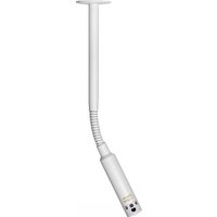
M40W6S - Microphone Audix - Free user manual and instructions
Find the device manual for free M40W6S Audix in PDF.


| Product Type | Dynamic Microphone |
| Brand | Audix |
| Model | M40W6S |
| Frequency Response | 50 Hz - 16 kHz |
| Polar Pattern | Cardioid |
| Impedance | 250 ohms |
| Sensitivity | -54 dBV/Pa |
| Connector Type | 3-pin XLR |
| Dimensions (Height x Diameter) | 165 mm x 52 mm |
| Weight | 300 g |
| Power Source | No external power required (dynamic) |
| Housing Material | Die-cast zinc alloy |
| Finish | Black matte |
| Application | Live vocals, speech, instrument miking |
| Included Accessories | Mic clip, carrying pouch, user manual |
| Maintenance | Clean grille with mild soap and water; avoid moisture |
| Safety | Keep away from water and extreme temperatures |
| Spare Parts | Replacement grilles and capsules available |
| Repairability | Replaceable capsule and cable |
Frequently Asked Questions - M40W6S Audix
User questions about M40W6S Audix
0 question about this device. Answer the ones you know or ask your own.
Ask a new question about this device
Download the instructions for your Microphone in PDF format for free! Find your manual M40W6S - Audix and take your electronic device back in hand. On this page are published all the documents necessary for the use of your device. M40W6S by Audix.
USER MANUAL M40W6S Audix
natural_image
3D rendering of two medical or industrial devices labeled 'AUDIX M50' and 'AUDIX M51', with a mesh-patterned ceiling fixture in the background (no text or symbols on the devices themselves)AUDIX M40 INSTALLATION GUIDE
Thank you for choosing Audix! Our products are designed to provide you with many years of reliable service. Please read this manual before using the system for optimal installation and operation.
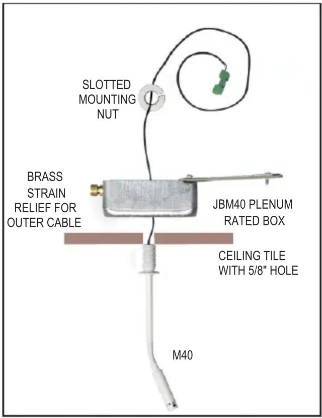
M40 JUNCTION BOX ASSEMBLY

natural_image
3D diagram of a simple mechanical device with a curved pipe and rectangular housing, labeled 'BOTTOM VIEW OF JUNCTION BOX' (no other text or symbols)• DRILL 5/8 INCH HOLE IN THE CEILING TILE.
• OPEN JMB40 BOX LID AND PLACE BOX ON TOP OF 5/8 INCH HOLE IN THE CEILING TILE. (SEE #1)
- PLACE JBM40 BOX OVER THE CEILING TILE 5/8 INCH HOLE.
• INSERT M40 THREADED CEILING MOUNT THROUGH CEILING TILE AND INTO THE JBM40 BOX
• SECURELY TIGHTEN THE KNURLED NUT. (SEE #2)
- INSERT PLENUM WIRE (BELDEN 9451P OR 82761 OR EQUIVALENT THROUGH STRAIN RELIEF (SEE #3) AND TERMINATE TO MATING PHOENIX CONNECTOR. (SEE #4 AND #5)
• TIGHTEN PLENUM CABLE STRAIN RELIEF AND CLOSE LID OF JMB40 BOX. (SEE #5)
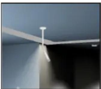
• POSITION MICROPHONE TO DESIRED ANGLE.
INSTALLATION AND WIRING INSTRUCTIONS FOR AUDIX M40 CEILING MICROPHONES
1

natural_image
Close-up of a white rectangular electronic enclosure with a central hole and attached circuit breakers (no visible text or symbols)Open lid of JBM40 box and place on top of ceiling tile drilled hole.
2

natural_image
Interior view of an open electrical enclosure with a central component and a red arrow pointing to it (no visible text or symbols)Insert ceiling mount through ceiling tile hole, and into JBM40 box then tighten the knurled nut.
3

natural_image
Close-up of an open electronic device casing with wires and a green connector, no visible text or symbolsInsert plenum wire through strain relief nut, then connect to the Phoenix terminal.
Recommended cable: Belden 9451P - .124" O.D. or Belden 82761 - .116" O.D.
4
natural_image
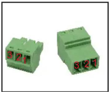
Two green electronic component blocks with red numbers 3 and 2, no visible text or symbols on the blocks themselves.Wiring:
1 = Ground
2 = Blue (+)
3 = Yellow (-)
5

natural_image
Close-up of an open electrical enclosure with a green connector and wiring (no visible text or symbols)Connect Phoenix terminals.
6

natural_image
Close-up of a hand holding a wire coil mounted on a metal enclosure, with a green component inserted (no visible text or symbols)Tighten the strain relief nut. Arrange excess wire in box and fasten lid.
7
natural_image
Close-up of a ceiling-mounted lampshade with a white adjustable shade and light beam (no text or symbols visible)Position microphone to desired angle.
For further information contact
Audix at 503.682.6933
www.audixusa.com
SEISMIC RESTRAINT INSTRUCTIONS
CABLE EXPLODED VIEW:

Wrap the cable around a beam, eyebolt or hanger. Next, slip the cable through the top of cable stay barrel pulling excess cable until taut.
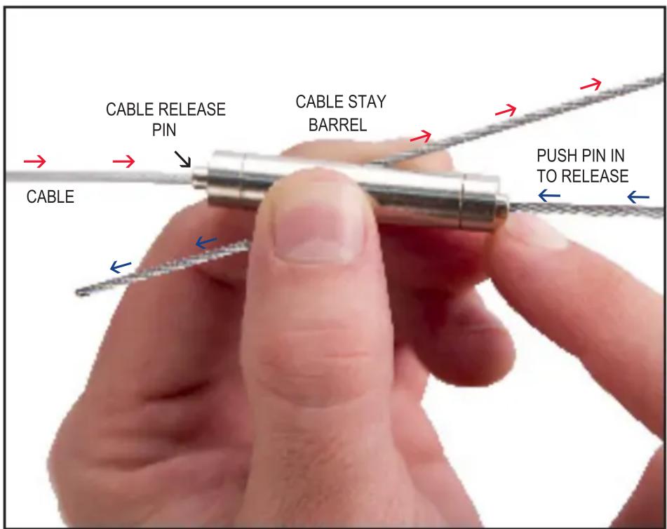
To release cable, depress the cable release pin on top, to release the loop, or on bottom, to extend cable length.
Brand : Audix
Model : M40W6S
Category : Microphone