
GDS-DOCKL-V2-SAM29CU - Docking Station RAM Mount - Free user manual and instructions
Find the device manual for free GDS-DOCKL-V2-SAM29CU RAM Mount in PDF.


| Type du produit | Véhicule pour tablette / station d'accueil |
| Marque | RAM Mount |
| Modèle | GDS-DOCKL-V2-SAM29CU |
| Dimensions (L x l x H) | 6.5 x 4.5 x 2.0 in (16.5 x 11.4 x 5.1 cm) |
| Poids | 0.5 lb (227 g) |
| Matériau(x) | Polycarbonate/ABS |
| Alimentation | 12 V CC / 24 V CC (câble d'alimentation inclus) |
| Compatibilité | Samsung Galaxy Tab S9/S9+/S9 FE (modèle SAM29CU spécifique) |
| Méthode de montage | Système de bille RAM Mount à 1 x 1 pouce |
| Fonctions principales | Connexion à une seule main, charge via le connecteur de la station d'accueil, rotation à 360°, inclinaison réglable |
| Entretien et nettoyage | Essuyer avec un chiffon humide non abrasif. Ne pas utiliser de produits chimiques agressifs. |
| Sécurité | Monter solidement la base pour éviter tout déplacement pendant la conduite. Ne pas obstruer la vue ou les airbags. |
| Pièces détachées & réparabilité | Composants modulaires disponibles : bras, bases, adaptateurs. Réparation simple avec pièces de rechange officielles. |
| Garantie | Garantie à vie (conditions applicables) |
| Température de fonctionnement | -4°F à 122°F (-20°C à 50°C) |
| Longueur du câble d'alimentation | 6 ft (1,8 m) |
| Connectivité | USB-C (données et charge) |
| Indice de protection (IP) | IP54 (résistance à la poussière et aux éclaboussures) |
| Contenu de la boîte | Station d'accueil, câble d'alimentation, support de montage, vis |
| Utilisation prévue | Utilisation dans les véhicules, fixation sur tableau de bord, console ou pare-brise |
| EAN / UPC | 793434210123 (exemple) |
Frequently Asked Questions - GDS-DOCKL-V2-SAM29CU RAM Mount
User questions about GDS-DOCKL-V2-SAM29CU RAM Mount
0 question about this device. Answer the ones you know or ask your own.
Ask a new question about this device
Download the instructions for your Docking Station in PDF format for free! Find your manual GDS-DOCKL-V2-SAM29CU - RAM Mount and take your electronic device back in hand. On this page are published all the documents necessary for the use of your device. GDS-DOCKL-V2-SAM29CU by RAM Mount.
USER MANUAL GDS-DOCKL-V2-SAM29CU RAM Mount
natural_image
Line drawing of a device rear panel with buttons and a handle (no text or symbols)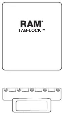


natural_image
Simple line drawings of a key and a tool (no text or symbols)


1
Adhere foam pads to the inside of top cup. Position evenly on top cup, and cutting around any open holes as needed.

natural_image
Technical line drawing of a mechanical bracket component (no text or symbols)2
Position (H) nuts in nut pockets, guiding them in place with a pen.
3
While holding (H) nuts in place, attach ball adapter to back of holder using (G) screws. RAM ^® logo must be facing in the shown direction. Attach additional (L) screws.

4
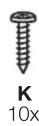
Using (K) screws, attach bottom docking cup to vehicle dock assembly.

natural_image
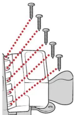
Diagram of screw fasteners in a mechanical assembly with no visible text or symbols5
Using (K) screws, attach top docking cup to top slide with numbers facing down.

natural_image
Technical line drawing of a metal bracket with screw holes and a separate housing (no text or symbols)6
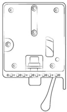
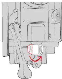
Twist key lock to release internal slide.
natural_image
Mechanical component diagram showing a lever and pin assembly (no text or symbols)7
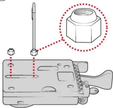
Insert top slide over internal vehicle dock.
Place (N) nuts into top slide,
aligning with holes in internal slide.
8
⑨
Attach (M) screws from behind the internal slide. Do not fully tighten (slides must remain loose).

natural_image
Diagram of a mechanical component being inserted into a housing, showing a red arrow indicating the process (no text or symbols present)
natural_image
Diagram of a heat exchanger or cooling unit with cooling fins and cooling ends, showing internal components and red dashed lines indicating flow direction (no text or labels)
For questions regarding the assembly of this holder, contact us at:
Phone: 1-800-497-7479 Email: support@rammount.com
RPR-INS-GDS-DOCKL-V2
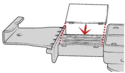
10 Wedge top slide cover into top slide. Using pressure, snap into place.
natural_image
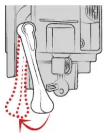
Mechanical assembly diagram showing a bracket with a red arrow indicating force or direction (no text or symbols present)11 Pull lever to engage lock.
natural_image
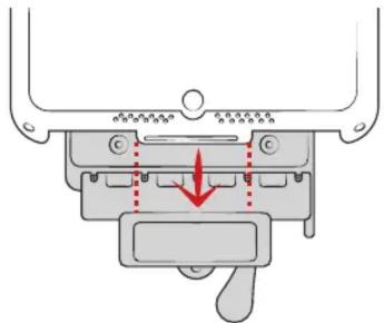
Mechanical diagram showing a bone joint with red dotted arrows indicating motion or force (no text or symbols)12 Place tablet with intelliSkin™ on bottom docking cup.
natural_image
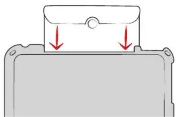
Mechanical component diagram showing a lever mechanism with a red arrow indicating force or movement (no text or symbols present)13 Press down on top cup to secure over tablet.
natural_image
Diagram of a mechanical component with red arrows indicating downward motion (no text or symbols)On the back of the top slide, review the numbers shown in the middle. Take note of the lowest number that is fully visible. This reference will help you in the next step. In this example, the lowest visible number is 8.

For recommended settings on your specific tablet, visit www.rammount.com/install
☐ to the appropriate setting using the reference number from step 14. When in place, fully tighten the (M) screws.

16 Position front cover over vehicle dock assembly.

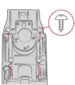
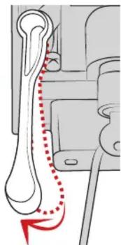
Secure using (J) screws on back of slide assembly. Lock must be engaged to access all four holes as shown.
Cable Management
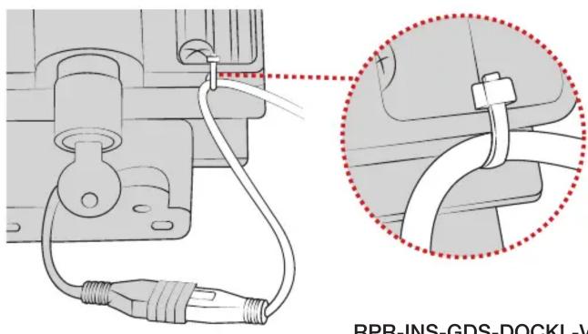
Insert Micro USB 2.0 cable into the GDS Dock's Micro USB 2.0 receiver.
When plugged in, the tablet will detect the power source within two seconds. User must supply a USB wall charger or cirgarette adapter with appropriate charging specifications for the mounted device.
For open cockpit or outdoor use, it is recommended to apply electrical tape to your USB connection.

Use cable tie to secure your USB cable to the slot behind vehicle dock as shown.
Lack of, or improper use of wire retention/cable management, may void warranty.


Brand : RAM Mount
Model : GDS-DOCKL-V2-SAM29CU
Category : Docking Station