DX-5330 - Tripod Magnus - Free user manual and instructions
Find the device manual for free DX-5330 Magnus in PDF.


| Product Type | Tripod |
| Brand | Magnus |
| Model | DX-5330 |
| Maximum Height | 165 cm (65 in) |
| Minimum Height | 50 cm (20 in) |
| Folded Length | 55 cm (22 in) |
| Weight | 2.5 kg (5.5 lbs) |
| Load Capacity | 8 kg (17.6 lbs) |
| Material | Aluminum alloy |
| Leg Sections | 4 |
| Leg Lock Type | Flip lock |
| Head Type | Fluid pan/tilt |
| Quick Release Plate | Yes, standard |
| Bubble Level | Yes |
| Rubber Feet | Yes, with retractable spikes |
| Center Column | Geared, with hook for stabilizing weight |
| Included Accessories | Carrying bag, tool kit |
| Cleaning | Wipe with dry cloth; avoid solvents |
| Safety | Do not exceed load capacity; tighten locks before use |
Frequently Asked Questions - DX-5330 Magnus
User questions about DX-5330 Magnus
0 question about this device. Answer the ones you know or ask your own.
Ask a new question about this device
Download the instructions for your Tripod in PDF format for free! Find your manual DX-5330 - Magnus and take your electronic device back in hand. On this page are published all the documents necessary for the use of your device. DX-5330 by Magnus.
USER MANUAL DX-5330 Magnus
Thank you for choosing Magnus.
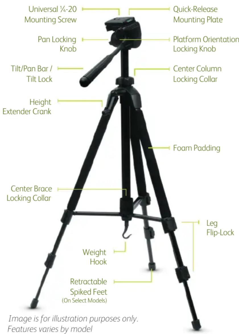
Congratulations on the purchase of your new Magnus tripod. This tripod features an adjustable center column for smooth and precise camera height adjustment, and telescoping legs with flip-locks for fast and easy leg adjustments. The three-way pan & tilt head gives you total control over camera positioning, and the quick-release plate features a 1/4"-20 male thread for universal camera mounting. There is also a bubble level to ensure that your shot is properly aligned.
Please read and follow these instructions, and keep this manual in a safe place.
Photo Tripod Components
Opening the Tripod
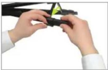
1 Always extend the legs from the top flip-locks first. Pull out on each flip-lock and extend the legs to the desired height. Relock each leg (Fig. A-B)
natural_image
Close-up of hands assembling a black plastic component with a yellow triangular tag (no text or symbols visible)Figure A Figure B

natural_image
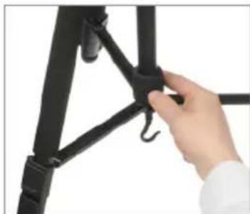
Close-up of hands assembling a black mechanical component with a green arrow indicating motion (no text or symbols visible)2 Rotate the locking collar counterclockwise to release the center brace, and gently pull the legs out. Push down on the center brace, and then rotate the locking collar clockwise to lock the legs in place (Fig. C)
natural_image
Close-up of a hand adjusting a black metal bracket with a hook (no text or symbols visible)Figure C
Mounting the Quick-Release Plate to the Camera
1 To remove the quick-release plate from the tripod head, pull and hold the plate locking lever and remove the quick-release plate (Fig. D)

natural_image
Close-up of hands adjusting a black camera clip on a tripod (no text or symbols visible)Figure D
2 Line up the quick-release plate lengthwise with the bottom of the camera. Match the quick-release plate screw to the camera's mounting thread, and mount the plate to the camera by rotating the screw clockwise until snug (Fig. E)

natural_image
Close-up of hands holding a black camera module (no visible text or symbols)Figure E
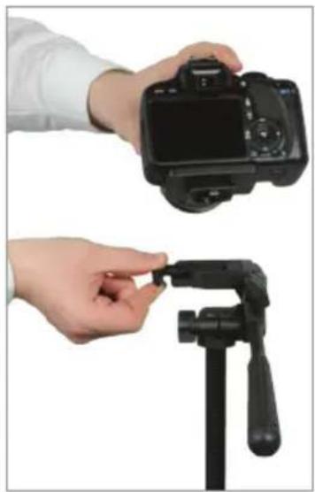
3 Make sure the screwhead handle is flat against the bottom of the quick-release plate. Mount the camera/quick-release plate assembly to the tripod head by pulling and holding back on the plate locking lever. Insert the camera/quick-release plate assembly and push the plate locking lever to lock it in place (Fig. F)
natural_image
Two hands holding a DSLR camera and a black tripod stand, both without any visible text or symbols.Figure F
Utilizing the Pan & Tilt Head
To utilize the tilt feature, loosen the pan & tilt bar by rotating it counterclockwise. Tilt the tripod head to the desired angle, and then rotate the pan & tilt bar clockwise to lock the new position (Fig. G)

natural_image
Hand holding a black tripod-mounted camera with a green motion arrow indicating rotation (no text or symbols)Figure G
2 To utilize the 360° panning feature, loosen the panning locking knob by rotating it counterclockwise. Pan as necessary, and then rotate the panning locking knob clockwise to lock the new position (Fig. H)

natural_image
Hand adjusting a black tripod mount on a white shirt (no text or symbols visible)Figure H
3 To change the camera orientation from horizontal to vertical position, loosen the platform locking
knob by rotating it counterclockwise. Rotate the platform 90°, and then rotate the platform locking knob clockwise to lock the new position (Fig. I)

natural_image
Hand holding a black tripod-mounted camera mount, no visible text or symbolsFigure 1
Adjusting the Center Column Height
1 To raise or lower the center column, loosen the center column collar by rotating it counterclockwise (Fig. 1)

natural_image
Close-up of hands adjusting a black camera tripod mount (no text or symbols visible)Figure 1
2 Wind the crank clockwise to raise the center column to the desired height, or counterclockwise to lower it. Rotate the center column collar clockwise to lock the new position (Fig. K)

natural_image
Close-up of hands adjusting a black tripod-mounted device with a green accent (no text or symbols visible)Figure K
All images are for illustration purposes only. Features varies by model
User Cautions
- Never set up or pull down a tripod while a camera is mounted
- Do not move the tripod or adjust the legs while a camera is mounted
- Do not exceed the maximum weight capacity of the tripod
- Never leave a camera unattended on the tripod
- The camera should be securely fastened to the quick-release mounting plate before mounting onto the tripod
- Never mount a camera to the tripod until all tripod legs are locked and stabilized
- Do not stand on, rest on, or hang anything from the mid-level spreader
- Do not attempt to remove the mid-level spreader
- Do not lift or move the tripod by the head
- Keep hands clear of the inside of the legs, to avoid trapping fingers
- The safe operation of the tripod is the responsibility of the user
ONE (1) YEAR LIMITED WARRANTY
This Magnus product is warranted to the original purchaser to be free from defects in materials and workmanship under normal consumer use for a period of one (1) year from the original purchase date or thirty (30) days after replacement, whichever occurs later. The warranty provider's responsibility with respect to this limited warranty shall be limited solely to repair or replacement, at the provider's discretion, of any product that fails during normal use of this product in its intended manner and in its intended environment. Inoperability of the product or part(s) shall be determined by the warranty provider. If the product has been discontinued, the warranty provider reserves the right to replace it with a model of equivalent quality and function. This warranty does not cover damage or defect caused by misuse, neglect, accident, alteration, abuse, improper installation or maintenance. EXCEPT AS PROVIDED HEREIN, THE WARRANTY PROVIDER MAKES NEITHER ANY EXPRESS WARRANTIES NOR ANY IMPLIED WARRANTIES, INCLUDING BUT NOT LIMITED TO ANY IMPLIED WARRANTY OF MERCHANTABILITY OR FITNESS FOR A PARTICULAR PURPOSE. This warranty provides you with specific legal rights, and you may also have additional rights that vary from state to state. To obtain warranty coverage, contact the Magnus Customer Service Department to obtain a return merchandise authorization ("RMA") number, and return the defective product to Magnus along with the RMA number and proof of purchase. Shipment of the defective product is at the purchaser's own risk and expense.
For more information or to arrange service, visit www.magnustripods.com or call Customer Service at 212-594-2353.
Brand : Magnus
Model : DX-5330
Category : Tripod