
PT-A-604 - Camera accessory Havis - Free user manual and instructions
Find the device manual for free PT-A-604 Havis in PDF.


| Product Type | Camera Accessory for Prisoner Transport Video System |
| Compatible Models | PT-A-601, PT-A-602, PT-A-603, PT-A-604, PT-A-607, PT-A-608 |
| Main Components | Panavise monitor mount bracket, Voyager 7" LCD Monitor, interior/exterior color cameras, camera mounting brackets, 6" Round 1/4" Lexan covers, 25 ft. camera cables, hardware kit |
| Power Supply | 12V DC (vehicle power) |
| Camera Type | Color camera with night vision LED (requires dome lights for proper operation) |
| Monitor Size | 7 inches LCD |
| Cable Length | 25 ft. per camera extension cable |
| Material | Metal brackets, polycarbonate dome covers |
| Installation Tools Required | Powered drills (3/8" & 1/2"), wire crimping tool, 4 1/2" hole saw or jig saw, standard socket set, drill bit set, ratcheting wrench, wire stripping tool |
| Hardware Included | #10 x 1/2" flat head machine screws, #10 keps nuts, #10 x 3/4" flat head sheet metal screws, 10-32 x 1/2" machine screws |
| Safety Precautions | Use rear compartment dome lights during operation; avoid drilling into wires; ensure polycarbonate dome cover fits properly before drilling |
| Water Resistance | Exterior camera is weather-resistant (installed on roof) |
| Warranty | Refer to Voyager instructions for warranty details |
| Technical Support | Havis, Inc. 1-800-524-9900 (USA) |
| Dimensions (approx.) | Monitor: 7" screen; Camera housing: ~3" diameter; Bracket: varies |
| Weight (approx.) | System weight: ~5-10 lbs depending on configuration |
| Operating Temperature | Standard vehicle interior operation |
| Spare Parts Availability | Yes, through Havis (part numbers provided in manual) |
| Repairability | Modular components; cables and cameras replaceable |
Frequently Asked Questions - PT-A-604 Havis
User questions about PT-A-604 Havis
0 question about this device. Answer the ones you know or ask your own.
Ask a new question about this device
Download the instructions for your Camera accessory in PDF format for free! Find your manual PT-A-604 - Havis and take your electronic device back in hand. On this page are published all the documents necessary for the use of your device. PT-A-604 by Havis.
USER MANUAL PT-A-604 Havis
INSTALLATION INSTRUCTIONS
PT-A-601, 602, 603, 604, 607 and 608
PRISONER TRANSPORT VIDEO SYSTEM EQUIPMENT
** Camera systems must be used with rear compartment dome lights ON. **
TOOLS REQUIRED:
| Powered Drills (3/8" & 1/2") | Wire Crimping Tool | 4 1⁄2" Hole Saw or Jig Saw Standard |
| Socket Set | Drill bit Set | Ratcheting Wrench |
| Wire Stripping Tool |
HARDWARE and parts for PT-A-601/602/603/604
| QTY | DESCRIPTION | PART # |
| 2/4/6/6 | #10 x 1/2" Flat head machine screw | GSM33380 |
| 4/8/12/12 | #10 Keps nut | GSM30028 |
| 3/6/9/9 | #10 x 3/4" Flat head sheet metal screw | GSM33151 |
| 2/4/6/6 | 10-32 x 1/2" Machine screw | GSM34447 |
Only on PT-A-604 (for exterior camera bracket mounting)
| QTY | DESCRIPTION | PART # |
| 2 | #10 X 3/4" Pan Head Sheet metal screw SS | GSM34170 |
MAIN VIDEO SYSTEM COMPONENTS
| QTY | DESCRIPTION | PART# |
| 1 | Panavise Monitor mount bracket | GSM70040 |
| 1 | Voyager 7" LCD Monitor with two (2) harnesses | GSM70003 |
| 1/2/3/3 | 6" Round 1/4" Lexan cover | PRM97353 |
| 1/2/3/3 | Camera mounting bracket | KKM007933 |
| 2/2/3/4 | Voyager 25 ft. Camera cable | GSM70021 |
| 1/2/3/4 | Interior/ Exterior Color Camera | GSM70033 |
PT-A-607 Clear Polycarbonate guard/Camera mount kit (Option only used for Customer Supplied Camera System) Not needed for PT-A-601, 602, 603 and 604 kits because parts are already included.
| QTY | DESCRIPTION | PART# |
| 3 | Camera mounting bracket | KKM007933 |
| 3 | Clear Polycarbonate dome covers | PRM97353 |
| 12 | 10-32 Keps nut | GSM30028 |
| 9 | #10 x 3/4" Flat head sheet metal screw | GSM33151 |
| 6 | 10-32 x 1/2" Flat head sheet metal screw | GSM33380 |
| 2 | #10 x 3/4" Sheet metal screw | GSM34170 |
| 6 | 10-32 x 3/8" Machine screw | GSM34447 |
PT-A-608 Digital Video Recorder kit (Optional)
| QTY | DESCRIPTION | PART# |
| 1 | Diesel Boss DVR with standard parts and cables | GSM70004 |
| 1 | Samsung 860 EVO 2.5 Inch SATA III Internal SSD 1 TB | GSM70005 (installed in DVR) |
| 4 | 4-PIN Female to RCA Female adaptor cable | GSM70025 |
| 1 | Voyager Male to RCA Female adaptor cable | GSM70026 |
| 1 | 4-PIN Male to RCA Male adaptor cable | GSM70029 |
| 4 | Voyager Female to RCA Male adaptor cable | GSM70034 |
| 4 | Voyager “Y” Dual Male to Single Female Splitter cable | GSM70035 |
| 1 | Equipment bracket for Havis Console | C-EB30-DB4-1P |

Determine mounting location for camera and mark hole. Be sure to make sure the polycarbonate dome cover fits properly before drilling 4 1/2 " hole. Take caution not to drill into any wires.
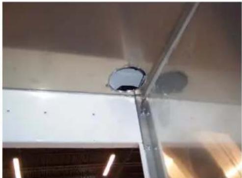
Once hole is drilled, deburr the metal. Reach through the opening and pull the camera cable through the opening.
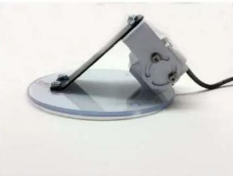
Attach camera to the Camera mounting bracket using two (2) 10-32 x 1/2" bolts and 10-32 keps nuts. Attach the bracket to the cover with two (2) 10-32 flat head screws and keps nuts.
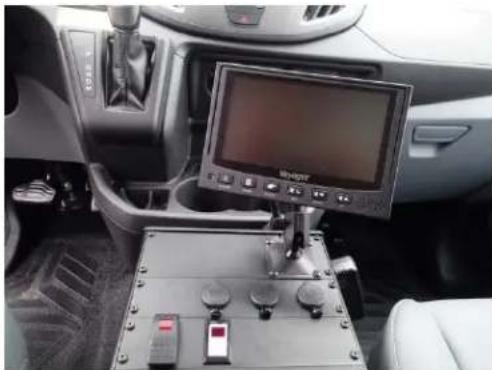
Wire system according to manufacture recommendations included within video system component boxes and the wire diagram supplied in this instruction

Plug camera cable into one of the camera assemblies. Turn on system. Position the camera to obtain optimal visibility within the compartment. You will need two people for this step.

Mark holes on the ceiling and pre-drill with 1/8" drill bit. Reposition camera assembly and mount using #10 x 3/4" Flat head sheet metal screws.
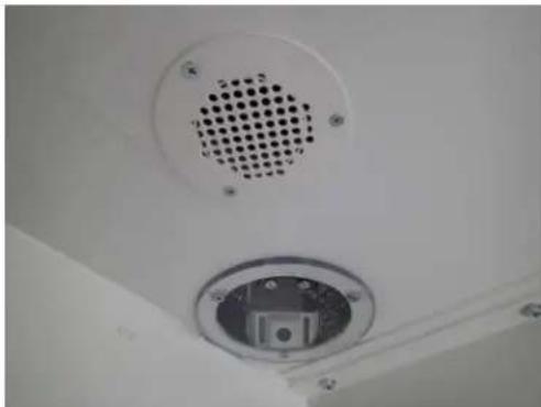
Repeat steps for remaining cameras.

Note: Cameras come standard with night vision LED lighting. However the night vision LED does not work correctly because of reflection off of the ceiling mounted vandal proof guard. Using rear dome lights when cameras are in use is always recommended to solve this issue.
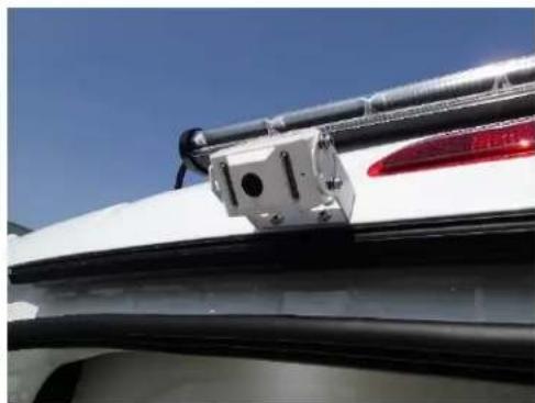
Mount external camera in desired location. If being used for viewing when backing up install camera on backside of roof as close to center as possible. The "U" shape bracket included with camera should work in most applications.
VOM74WP
Typical System Connection
See Voyager instructions included with monitor for operation and additional details
Also see Voyager instructions for warranty details and Tech Support information.
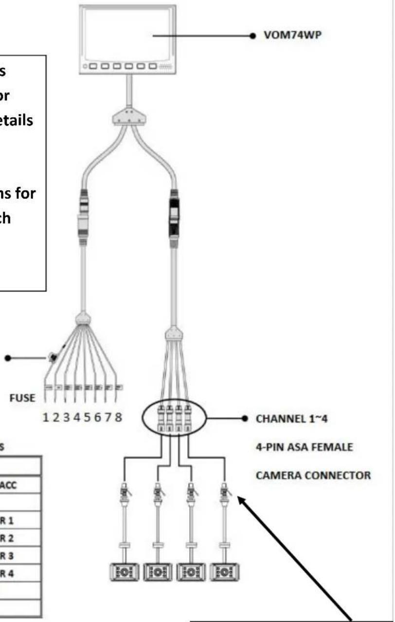
25 ft. Camera extension cables are installed here. One (1) per camera
POWER/TRIGGER WIRE FUNCTIONS
| REF # | WIRE COLOR | DESCRIPTION |
| 1 | RED | POWER 12V. (+) ACC |
| 2 | BLACK | GND |
| 3 | BLUE | CAMERA TRIGGER 1 |
| 4 | BROWN | CAMERA TRIGGER 2 |
| 5 | GREEN | CAMERA TRIGGER 3 |
| 6 | ORANGE | CAMERA TRIGGER 4 |
| 7 | WHITE | AUDIO TRIGGER |
| 8 | YELLOW | SPLIT TRIGGER |
PT-A-608 Digital Video Recorder - Helpful Notes and Details
- Download MDVR player software onto Windows computer. (included on thumb drive)
- User and Hardware manuals included on thumb drive. Printed copies also supplied.
- Use the remote and mouse to enter menu mode and change settings if desired.
- Remote and mouse are temporarily used for programming only.
- Remote requires two (2) AAA batteries. (not included)
- Record up to 600 hours for three cameras / 400 hours for four cameras on 1TB hard drive. Video will record continuously before over writing from the beginning.
- Remove Hard Drive for downloading video files with supplied SATA-USB cable.
- Additional RCA video extension cable (not included) may be needed depending on desired monitor & DVR locations. (goes between GSM70026 and GSM70029 cables)
- Connecting DVR trigger wires are optional connections. It is up to end user to determine if they require these for automatic record features.
- PT-A-608 kit includes parts for connecting up to four (4) Voyager cameras.
- DVR wiring includes cable adaptor for 5 thru 8 cameras. This cable is not used.
- It is necessary to access DVR menu to change from eight (8) to four (4) camera views. With DVR menu showing on monitor, right click mouse to open Multiview choices and select four camera (quad) view. See DVR User's manual for more details. (Only needed when viewing on monitor for programming or live playback)
- Refer to page (7) & (8) on these instructions for details on how to view DVR menu and change programming if desired.
- Voyager Camera system has a separate settings menu. See Voyager instruction manual included in kit for details.
- For additional support from Havis, Inc. call 1-800-524-9900
PT-A-608 Digital Video Recorder kit
Wire schematic for Voyager monitor and camera interface
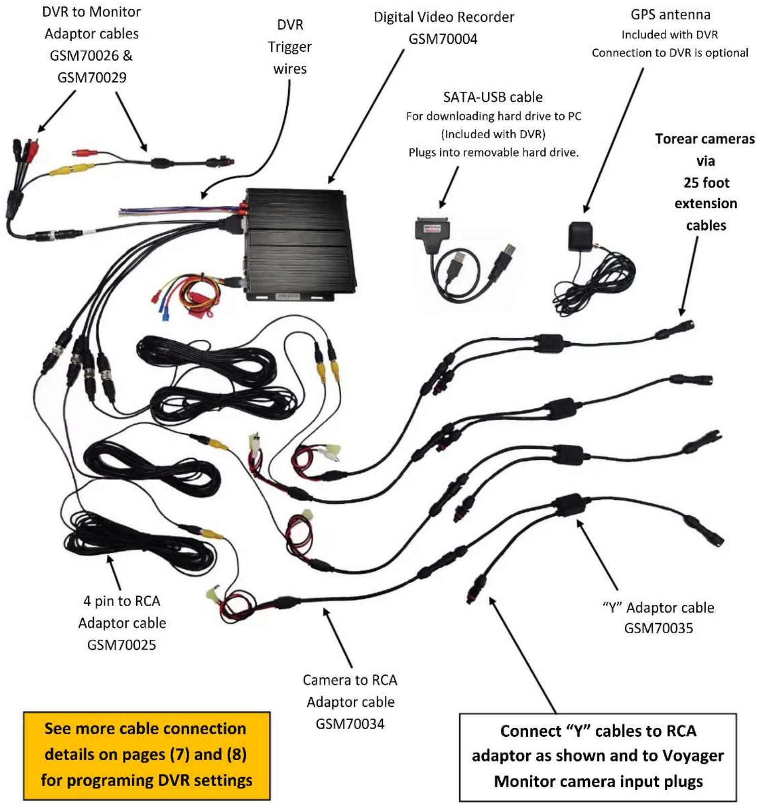

GSM70004 DVR
Shown with C-EB30-DB4-1P equipment bracket for mounting in Havis console.

GSM70025
4-PIN Female to RCA Female adaptor Four (4) Included with DVR kit

GSM70026
Voyager Male to RCA Female adaptor For DVR (AV out) to Monitor

GSM70029
4-PIN Male to RCA Male adaptor For DVR (AV out) to Monitor

GSM70034
Voyager Female to RCA Male adaptor NOTE: Red and Black power wires and White RCA cable not used with this video system.

GSM70035
Voyager "Y" Dual Male to Single Female Splitter adaptor
DVR Menu viewing Method 1
Without optional GSM70006 monitor
Note 1:
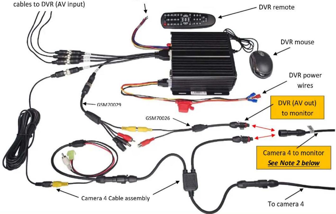
If you are using a 1, 2, or 3 camera system. The AV out of the DVR will stay connected to the monitor. This will allow the menu to be accessed and programmed without changing plug connections. Remote and mouse will still be needed for programing
Cameras 1, 2 and 3 from monitor / camera "Y" cables to DVR (AV input)
Trigger wires
Havis, Inc.
75 Jacksonville Road
Warminster, PA 18974
T 800-524-9900 F 215-957-0729
www.havis.com

View of Voyager monitor with DVR menu. Use DVR instructions along with remote and mouse for changing DVR settings.
Note 2:
If you have a four (4) camera system (Without optional GSM70006 monitor) the DVR menu settings are only able to be viewed and programmed by following the above cable routing because the Voyager monitor only has four (4) video inputs.
Using one of the camera inputs to the monitor, temporarily connect the AV out of the DVR to a monitor camera input.
You will only be able to view DVR menu when AV out is temporarily connected to monitor camera input.
Plug camera cable back into monitor when done programing.
This method of changing settings has proved to be very successful in eliminating video tampering.
DVR Menu viewing Method 2
With optional GSM70006 monitor
Used for viewing menu and reprogramming the DVR standard default settings instead of using Voyager monitor shown in method 1.
It is recommended to use this for programing only and to unplug / remove from vehicle when done.

Cameras 1, 2, 3 and 4 from monitor / camera "Y" cables to DVR (AV input)

GSM70006 Optional Mini monitor


- INSTALLATION INSTRUCTIONS
- PT-A-601, 602, 603, 604, 607 AND 608
- PRISONER TRANSPORT VIDEO SYSTEM EQUIPMENT
- VOM74WP
- TYPICAL SYSTEM CONNECTION
- PT-A-608 DIGITAL VIDEO RECORDER - HELPFUL NOTES AND DETAILS
- PT-A-608 DIGITAL VIDEO RECORDER KIT
- WIRE SCHEMATIC FOR VOYAGER MONITOR AND CAMERA INTERFACE
- DVR MENU VIEWING METHOD 1
- NOTE 1
- NOTE 2
- DVR MENU VIEWING METHOD 2
Brand : Havis
Model : PT-A-604
Category : Camera accessory