
BCD-1000DG - Post Display SAMSUNG - Free user manual and instructions
Find the device manual for free BCD-1000DG SAMSUNG in PDF.


| Product Type | Pole Display |
| Model Number | BCD-1000DG |
| Display Technology | LED or VFD (estimated) |
| Character Format | 2 lines x 20 characters (estimated) |
| Dimensions (W x H x D) | 143 mm x 80 mm x 50 mm (estimated) |
| Weight | 0.5 kg (estimated) |
| Power Supply | 5V DC via USB or RJ45 (estimated) |
| Communication Interface | RS-232 Serial (estimated) |
| Brightness | Adjustable (estimated) |
| Viewing Angle | 120° horizontal, 60° vertical (estimated) |
| Operating Temperature | 0°C to 40°C (estimated) |
| Mounting Type | Pole mount (VESA compatible, estimated) |
| Customer Display Functions | Scroll, blink, and custom character support |
| Compatible Systems | Windows, Linux, and most POS systems |
| Included Accessories | Pole mount bracket, power adapter (optional), serial cable |
| Maintenance | Wipe with dry cloth; avoid liquids |
| Safety | CE, FCC certified (estimated) |
| Repairability | Modular design; replaceable display module and control board |
Frequently Asked Questions - BCD-1000DG SAMSUNG
User questions about BCD-1000DG SAMSUNG
0 question about this device. Answer the ones you know or ask your own.
Ask a new question about this device
Download the instructions for your Post Display in PDF format for free! Find your manual BCD-1000DG - SAMSUNG and take your electronic device back in hand. On this page are published all the documents necessary for the use of your device. BCD-1000DG by SAMSUNG.
USER MANUAL BCD-1000DG SAMSUNG
User's Manual BCD-1000 Series
Customer Display Rev. 1.04
natural_image
Technical line drawing of four different electronic device mounting brackets (no text or symbols)■ Safety Precautions
In using the present appliance, please keep the following safety regulations in order to prevent any hazard or material damage.

WARNING
Violating following instructions can cause serious injury or death.
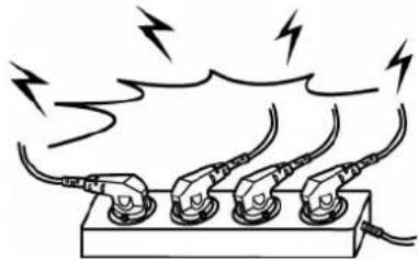
Do not plug several products in one multi-outlet.
• This can provoke over-heating and a fire.
- If the plug is wet or dirty, dry or wipe it before usage.
- If the plug does not fit perfectly with the outlet, do not plug in.
- Be sure to use only standardized multi-outlets.
PROHIBITED

natural_image
Diagram of three electrical insulators connected to a power outlet, with lightning bolts indicating current flow (no text or symbols)You must use only the supplied adapter.
- It is dangerous to use other adapters.
PROHIBITED


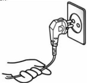
Do not pull the cable to unplug.
- This can damage the cable, which is the origin of a fire or a breakdown of the printer.
PROHIBITED

natural_image
Line drawing of a hand holding a cable connected to a wall socket (no text or symbols)Keep the plastic bag out of children's reach.
• If not, a child may put the bag on his head.
PROHIBITED


natural_image
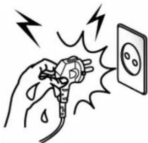
Cartoon illustration of a baby wearing a cap and holding a sheet of paper (no text or symbols)Do not plug in or unplug with your hands wet.
- You can be electrocuted.
PROHIBITED

natural_image
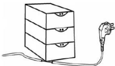
Illustration of a hand using a power plug to test electrical shock, with lightning bolts indicating electrical hazard (no text or symbols)Do not bend the cable by force or leave it under any heavy object.
• A damaged cable can cause a fire.
PROHIBITED

natural_image
Simple line drawing of a three-tiered storage cabinet connected to an electric plug (no text or symbols)
CAUTION
Violating following instructions can cause slight wound or damage the appliance.
If you observe a strange smoke, odor or noise from the Display, unplug it before taking following measures.
- Switch off the Display and unplug the set from the mains.
• After the disappearance of the smoke, call your dealer to repair it.
TO UNPLUG


Keep the desiccant out of children's reach.
- If not, they may eat it.
PROHIBITED


natural_image
Cartoon illustration of a baby wearing a cap and holding a small object (no text or symbols)Install the printer on the stable surface.
- If the Display falls down, it can be broken and you can hurt yourself.
PROHIBITED


Use only approved accessories and do not try to disassemble, repair or remodel it for yourself.
- Call your dealer when you need these services.
DISASSEMBLING
PROHIBITED


Do not let water or other foreign objects in the Display.
- If this happened, switch off and unplug the Display before calling your dealer.
PROHIBITED



Table of Contents
1. Complete Product Configuration....6
2. Unpacking .... 7
2-1 BCD-1000D TYPE 7
2-2 BCD-1000DN TYPE 7
2-3 BCD-1000W TYPE 8
2-4 BCD-1000WN TYPE 8
3. Defaults & Options by Product Type....9
3-1 SERIAL TYPE....9
3-1-1 Direct Type : Direct connection with the VFD, bypassing the Board....9
3-1-2 Pass through Type.... 10
4. Connection Type & Size.... 11
4-1 BCD-1000D TYPE 11
4-2 SIZE 12
4-2-1 Desk Top Type 12
4-2-2 Wall Mount Type 12
4-2-3 Etc. 12
5. Function....13
5-1 ROTATION.... 13
5-2 ANGLING 14
6. Connection .... 15
6-1 DIRECT TYPE PIN CONNECTION.... 15
6-1-1 Interface Specification 15
6-1-2 Connector Signal Assignments.... 16
6-1-3 Installation Instructions 17
6-1-4 Signal Assignments (Cable-end DSUB).... 17
6-1-5 DC Power Jack.... 17
6-2 SERIAL PIN CONNECTION 18
6-2-1 Host interface connector.... 18
6-2-2 Host interface connector signal assignments .... 18
6-2-3 Printer interface connector....19
6-2-4 Printer interface connector signal assignments 19
7. Switches ...... 20
7-1 DISPLAY SWITCH....20
7-2 DIP SWITCHES 20
7-3 MEMORY SWITCHES 21
8. Power Control 22
8-1 SERIAL BOARD 23
8-1-1 Jumper1....23
8-1-2 Jumper2....23
9. Appendix ...... 24
9-1 SPECIFICATIONS....24
9-2 CERTIFICATION 24
9-3 LABEL TYPES 25
1. Complete Product Configuration
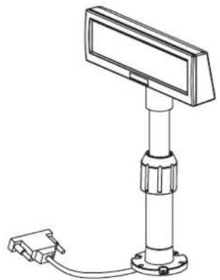
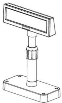
The display types offered include the following :
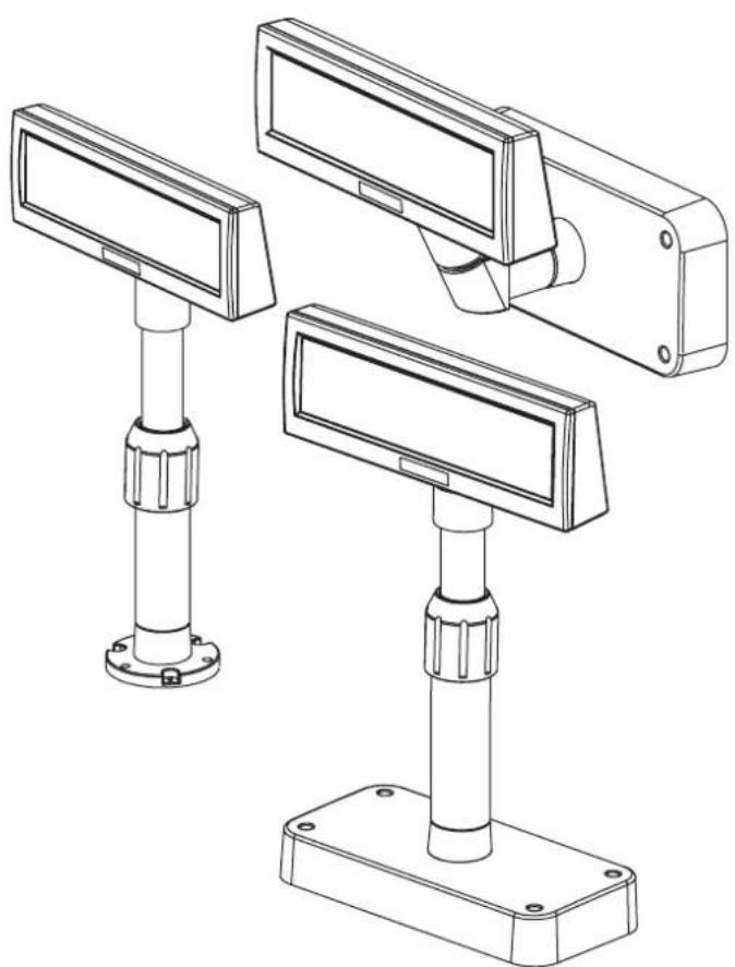
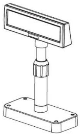
- Desk-Top Type (BCD-1000D)
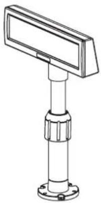
- Desk-Top Fix Type (BCD-1000DN),
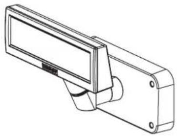
- Wall Mount Types (BCD-1000W/WN)..
natural_image
Technical line drawing of a mounted electronic device with a vertical column and base, connected to a small connector (no text or symbols present)BCD-1000DN
natural_image
Technical line drawing of a mechanical support device with a rectangular top and base (no text or symbols)BCD-1000D

natural_image
Line drawing of a rectangular security camera with mounting bracket (no text or symbols)BCD-1000WN

natural_image
Technical line drawing of a mechanical device with a rectangular housing and mounting feet (no text or symbols)BCD-1000W
NOTES
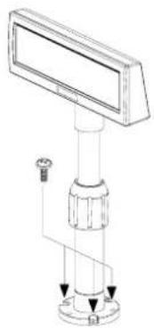
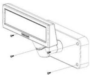
For the wall-mounting and table installation, please use an electric screwdriver.
natural_image
Technical line drawing of a mechanical device with a central shaft and mounting base (no text or symbols)BCD-1000DN / WN
natural_image
Technical line drawing of a mechanical device with mounting flanges and a screen (no text or symbols)BCD-1000D / W
2. Unpacking
2-1 BCD-1000D Type
natural_image
Technical line drawing of a mechanical support device with a rectangular panel and cylindrical base (no text or symbols)Display Set

Manual

Install CD
2-2 BCD-1000DN Type
natural_image
Technical line drawing of a mechanical sensor or gauge component (no text or symbols)Display Set

Manual

Install CD

natural_image
Four identical screw fasteners arranged in a 2x2 grid (no text or symbols visible)Screw
(M3*10) Tapping
2-3 BCD-1000W Type
natural_image
Technical line drawing of a mechanical device with a rectangular housing and mounting bracket (no text or symbols)Display Set

Manual

Install CD
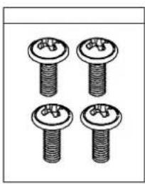
natural_image
Four identical screw fasteners arranged in a 2x2 grid (no text or symbols visible)Screw (M3*10) Tapping
2-4 BCD-1000WN Type
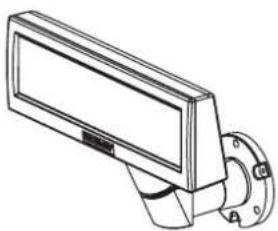
natural_image
Line drawing of a rectangular security camera with a mounted lens and mounting bracket (no text or symbols)Display Set

Manual

Install CD
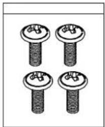
natural_image
Four identical screw fasteners arranged in a 2x2 grid, no text or symbols visibleScrew (M3*10) Tapping
3. Defaults & Options by Product Type
3-1 Serial Type
3-1-1 Direct Type : Direct connection with the VFD, bypassing the Board
| Item VFD- | Serial Etc | |
| Set Default |  | |
| Connection | Connection of Serial Jack via separate SMPSUsage Voltage: 5~24V(2pin)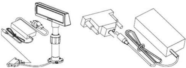 | |
| Power Default |  12V (K410-00004C,D,E,F,H,I) 12V (K410-00004C,D,E,F,H,I) |
3-1-2 Pass through Type
Host (PC) → VFD → Printer
| Item VFD- | Serial Etc | |
| Set Default |  | |
| Board Default | 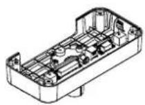 | |
| Power Option |    24V, 2.5A : 24V, 1.5A : 12V, 1.25A:K404-00007A K402-00008B K410-00004C,D,E,F,H,I 24V, 2.5A : 24V, 1.5A : 12V, 1.25A:K404-00007A K402-00008B K410-00004C,D,E,F,H,I | |
| Cable Option |  9PM.25PF (K604-00086A)Power Cable 3P/3P 1.8M (K610-00005B)Power Cable 3P/2P 1.8M (K610-00005G) 9PM.25PF (K604-00086A)Power Cable 3P/3P 1.8M (K610-00005B)Power Cable 3P/2P 1.8M (K610-00005G) |
4. Connection Type & Size
4-1 BCD-1000D Type
| Basic Units | 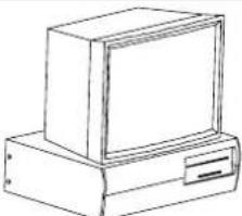 | 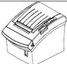 | 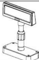 |  |
| Interface |   | 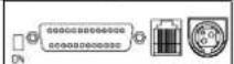 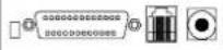 |  | |
| Power Connection Method 1 VFD Separate Power Supply |  | 5~24V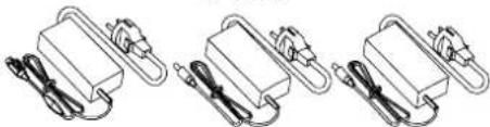 | ||
| Power Connection Method 2 SMPS→VFD →Pinter | 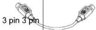 | 24V | ||
| Power Connection Method 3 SMPS→VFD →Pinter |  2 pin 3 pin 2 pin 3 pin | 24V | ||
| Cable Connection Method 1 Host→VFD →Printer |  | |||
| Cable Connection Method 2 |  | |||
| Etc | A: Power Supply Connector (Out DC 24V, 3pin)B: Host Interface Connector (D-SUB 25pin, Female)C: Power Supply Connector (In DC 5~24V, 2pin)D: Display Unit ConnectorE: Printer Interface Connector (D-SUB 9pin, Male)F: Power Supply Connector (In DC 24V, 3pin) | |||
4-2 Size
4-2-1 Desk Top Type
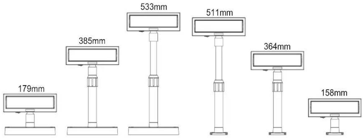
bar
| Dimension | Value (mm) | |---|---| | Top Left | 179 | | Top Right | 385 | | Top Center | 533 | | Top Right | 511 | | Top Center | 364 | | Top Right | 158 |4-2-2 Wall Mount Type
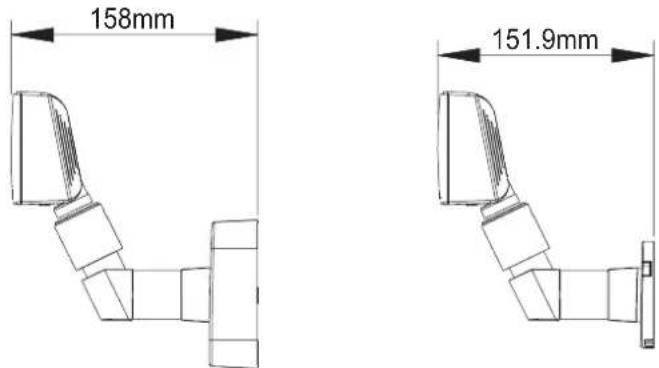
4-2-3 Etc.
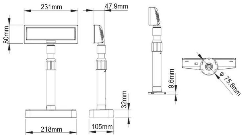
5. Function
5-1 Rotation
This product allows display rotation to any position or angle desired by the user. Please adhere to the following instructions during installation to prevent possible product damage and/or malfunction.
Following assembly, follow the sequence below to fix the DISPLAY in the desired position.

(a) Lower the DISPLAY UNIT in the direction of the arrow. Rotate the NUT-FIX to allow for lowering. (Please refer to the product OPEN/CLOSE label.)
(b) Rotate the DISPLAY UNIT to the desired angle.

Do not rotate the DISPLAY UNIT in any direction for more that one full revolution. (Beware as the DISPLAY UNIT can be rotated continuously.)
(C) After setting the DISPLAY to the desired position, secure the NUT-FIX. (When raising the DISPLAY UNIT, lateral movement is prevented.) Make sure to tighten the NUT-FIX after raising the DISPLAY UNIT to the desired height.

As excessive tightening of the NUT-FIX can result in product damage and/or malfunction, secure only to the extent that the DISPLAY UNIT is fixed and does not move.

As shown in figure (A), make sure to fully lower the DISPLAY UNIT before rotating. Rotation of the DISPLAY UNIT when it is not fully lowered will produce a clicking sound. This sound does not indicate any product breakage and is a result of the friction between the POLE-MAIN RIB and the rotation section within the POLE-ADJUST. If the DISPLAY UNIT is fully lowered, this sound will not be produced.
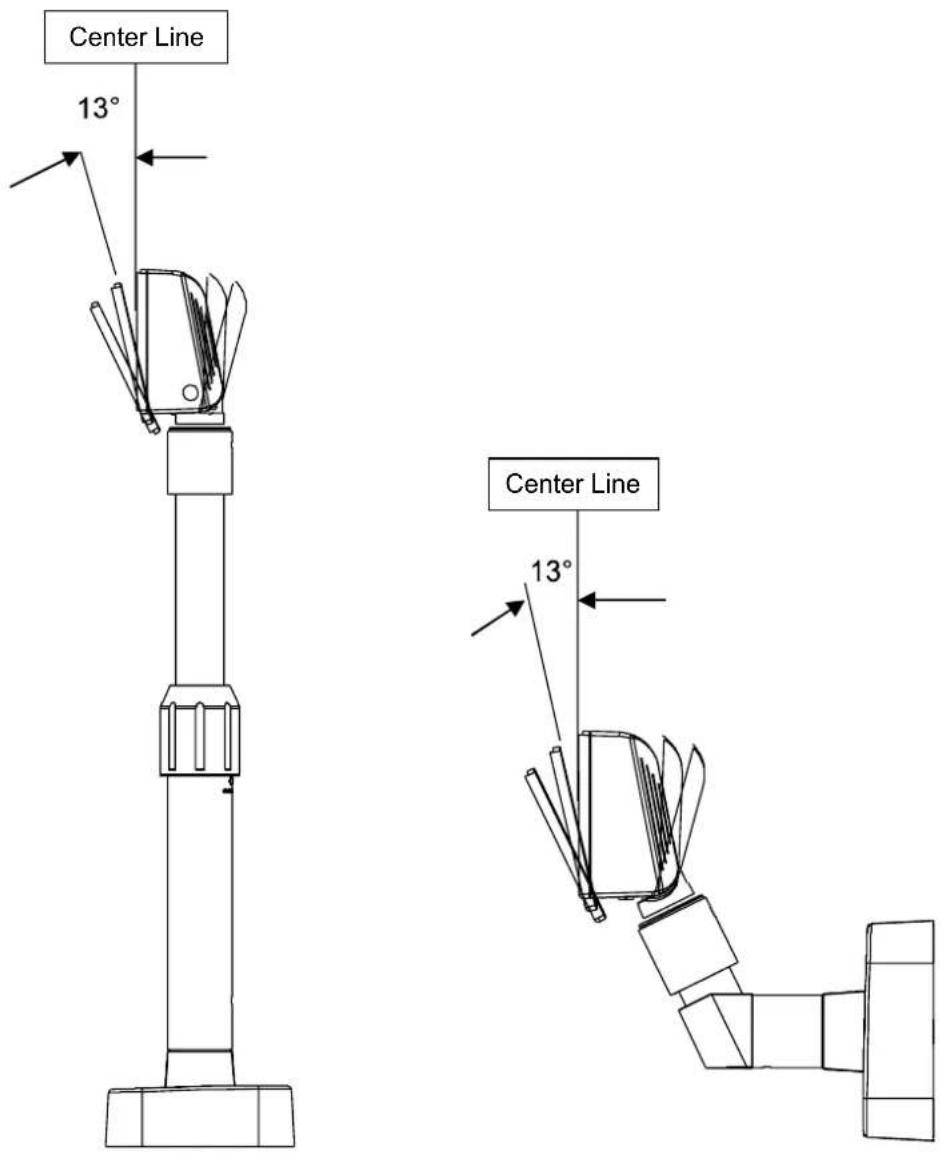
5-2 Angling
This product allows display tilting to any angle desired by the user. Please adhere to the following instructions during installation to prevent possible product damage and/or malfunction.
TILT ANGLE : The display can be angled left and right from the Center Line in 13° angle intervals for a total of 4 steps, 5 positions. (Angling: 52°max.)
6. Connection
6-1 Direct Type Pin Connection
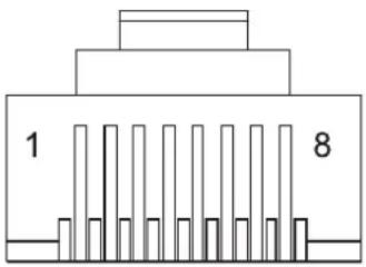
6-1-1 Interface Specification
| Signal specifications | |
| Data transmission Serial | |
| Synchronization | Synchronous |
| Handshaking (*) DTR/DSR control | |
| Signal levels MARK = -3 to -15 Vlogic = “1” OFFSPACE = +3 to +15 V logic = “0” ON | |
| Baud Rate (*) 1200, 2400, 4800, 9600, 19200, 38400, 57600, 115200 bps(bps : bits per second) | |
| Data word length (*) 7 bits, 8 bits | |
| Parity (*) None, odd, even | |
| Stop bits 1 or more | |
| (*) Selected by the DIP switches. | |
6-1-2 Connector Signal Assignments
| Pin NO | Signal Name | Signal Direction | Function |
| 1 | FG | - | Frame ground |
| 2 | TXD | Output | 1) When the BDC-1000 is connected with the data pass through(*1): Transmit data to the printer2) When the BDC-1000 is connected in a stand-alone: Transmit data to the host |
| 3 | RXD | Input | Receive data from the printer |
| 4 | DSR | Input | This indicates whether the printer is ready to receive data.1) When the BCD-1000 is connected with a data pass through(*1):[MARK]: The printer is not ready to receive data[SPACE]: The printer is ready to receive data2) When the BDC-1000 is connected in a stand-alone:[MARK]: The host is not ready to receive data[SPACE]: The host is ready to receive data |
| 5 | DTR | Output | This indicates whether the display is ready to receive data (*2).[SPACE] The display can receive data.[MARK] The display cannot receive data.[DTR MARK]DTR goes to MARK under the following conditions :1 The period from when the power is turned on to when the display first becomes ready to receive data.2 When the self-test is executed.3 When the remaining space in the receive buffer becomes 40bytes or less (buffer-full state).4 When [DSR MARK] is on, if the printer is selected by a peripheral device command. (When the BCD-1000 is connected with the data pass through.)(*1)[DTR SPACE]DTR goes to SPACE under the following conditions :1 When the display first becomes ready to receive data after power-on.2 When the self-test has ended.3 When the remaining space in the receive buffer becomes 50bytes or more after it became 40bytes or less once. |
| 6 | SG | - | Signal GND |
| 7 PS - Power supply terminal | |||
| 8 | PG | - Flyback line for power supply | |
NOTES
(*1) For the data pass through and the stand alone, refer to SVC Manual connection methods for detail.
(*2) [DTR MARK] can be set by the US v command. This case differs from the above-mentioned.[DTR MARK] Refer to the US v command in section 4, Command Description.
6-1-3 Installation Instructions
STEP1. Turn the computer system power off.
STEP2. Connect the Display Cable to the RS-232 Port of the Computer.
STEP3. Connect the DC Power source by the appropriate DC Power adapter.
STEP4. Turn on the computer and the power supply unit, the display will be on and ready for receiving data.
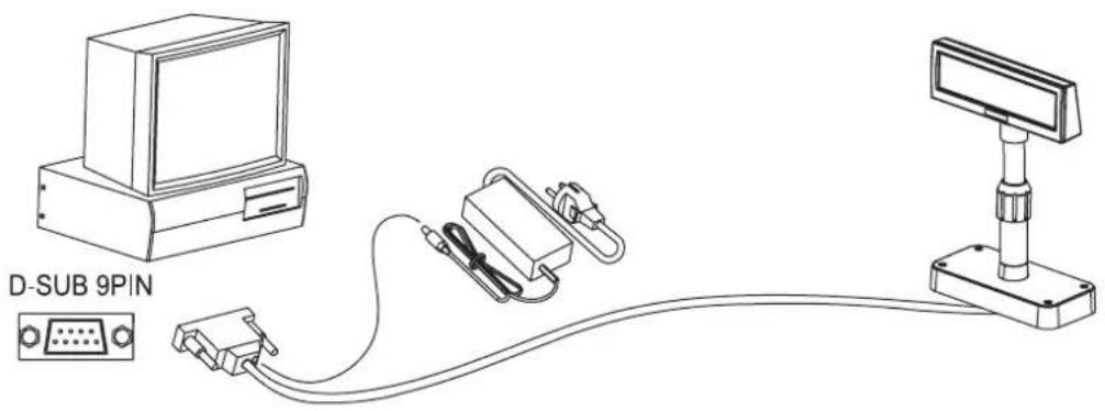
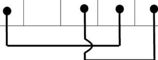
6-1-4 Signal Assignments (Cable-end DSUB)

| 1 | 2 | 3 | 4 | 5 | 6 | 7 | 8 | 9 | |
| pin Name NC RXD | TXD DTR GND | DSR RTS CTS NC | |||||||
| Short Connection | |||||||||
natural_image
Pure electrical circuit lines without any symbols6-1-5 DC Power Jack
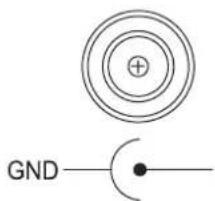
MAX 300 \~ 1350mA. +12VDC \~ +24VDC.
6-2 Serial pin Connection
6-2-1 Host interface connector
The option stand provides the host interface connector (D-SUB 25 pin Female type).
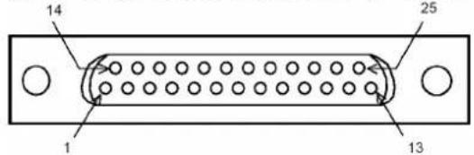
6-2-2 Host interface connector signal assignments
| PinNO | Signal Name | Signal Direction | Function |
| 1 | FG | - | Frame ground |
| 2 | TXD | Output | 1) When the BDC-1000 is connected when a passthrough connection :Transmit data to the host from the printer2) When the BDC-1000 is connected as a stand-alone :Transmit data to the host from the DM |
| 3 RXD Input | Receive data from the host (host → DM) | ||
| 4(*1) RTS Output Same as DTR | |||
| 6(*2) | DSR | Input | Indicates whether the host is ready to receive data.[SPACE] The host is ready to receive data.[MARK] The host is not ready to receive data. |
| 7 | GND | - | Signal ground |
| 20(*1) | DTR | Output | This indicates whether the display is ready to receive data.[SPACE] The display can receive data.[MARK] The display cannot receive data.[DTR MARK]DTR goes to MARK under the following conditions:1 The period from when the power is turned on to when the display first becomes ready to receive data.2 When the self-test is executed.3 When the remaining space in the receive buffer becomes 40bytes or less (buffer-full state).4 When [DSR MARK] is on, if the printer is selected by a peripheral device command.[DTR SPACE]DTR goes to SPACE under the following conditions:1 When the display first becomes ready to receive data after power-on.2 When the self-test has ended.3 when the remaining space in the receive buffer becomes 50bytes or more after it became 40bytes or less once. |
NOTES
(*1) Make sure to use either one of the RTS or the DTR terminal. Otherwise, the built-in RS-232 driver IC may be broken.
6-2-3 Printer interface connector
The option stand provides the printer interface connector (D-SUB 9 pin Male type).
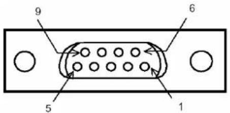
6-2-4 Printer interface connector signal assignments
| PinNO | SignalName | SignalDirection | Function |
| 2 | RXD | Input | Receive data from the printer (printer → host) |
| 3 TXD Output Transmit data to the printer (DM → Printer) | |||
| 4 DTR Output Indicates whether the host is ready to receive data.[SPACE] The host is ready to receive data.[MARK] The host is not ready to receive data. | |||
| 5 | GND | - | Signal |
| 6 DSR Input This indicates whether the display is ready to receive data from the printer.[SPACE] The printer can receive data. When the printer becomes ready to receive data the SPACE is output.[MARK] The printer cannot receive data.Even if the printer becomes readyto receive data, the MARK is not output. | |||
| 9 | RESET | Output | Reset signal to the printer (host → printer) |
7. Switches
7-1 Display Switch
7-1-1 Feature : A Display Switch is located on the bottom of the display panel.
7-1-2 Function : Turns the power supply on/off.
7-2 DIP switches
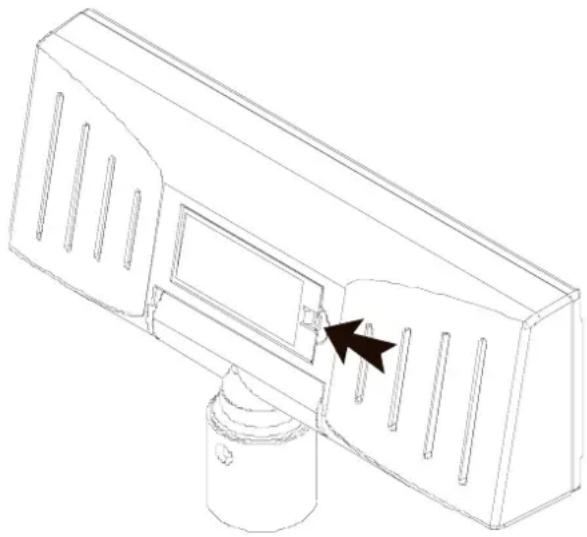
7-2-1 Feature : Two DIP switches are located on the back of the display panel. You can remove the DIP switch cover by pushing the hook.
natural_image
Technical line drawing of a mechanical component with a black arrow pointing to a specific part (no text or symbols present)※ CAUTION
Make sure if the dip switch cover is closed prior to power on
7-2-2 Functions : The DIP switch settings are read only when the power is turned on. Therefore, changing the settings while the power is on has no effect.
7-2-3 DIP S/W #1 Function (RS-232 Serial Input Setting)
| No. | Function Switch OFF | Switch ON | |||||||||
| 1 | Default Setting DIP Switch Values EEP-ROM Data Leading | ||||||||||
| 2 | N.C (No Connection) Reserved for Future Using Reserved for Future Using | ||||||||||
| 3 | Display Viewing Side Customer Side Operator Side | ||||||||||
| 4 | Self-test Execution Does not execute Executes | ||||||||||
| 5~8 | Command Emulation | Command Emulation | |||||||||
| 5 | 6 | 7 | 8 | Command Emulation | 5 | 6 | 7 | 8 | Command Emulation | ||
| 0 | 0 | 0 | 0 | Samsung VFD | 1 | 0 | 0 | 0 | NCR Real POS | ||
| 0 | 0 | 0 | 1 | Epson ESC/POS | 1 | 0 | 0 | 1 | PD6000 | ||
| 0 | 0 | 1 | 0 | ADM787/788 | 1 | 0 | 1 | 0 | ICD2002 | ||
| 0 | 0 | 1 | 1 | DSP800 | 1 | 0 | 1 | 1 | Reserved | ||
| 0 | 1 | 0 | 0 | AEDEX | 1 | 1 | 0 | 0 | Reserved | ||
| 0 | 1 | 0 | 1 | UTC Standard | 1 | 1 | 0 | 1 | Reserved | ||
| 0 | 1 | 1 | 0 | UTC Enhance | 1 | 1 | 1 | 0 | Reserved | ||
| 0 | 1 | 1 | 1 | CD5220 | 1 | 1 | 1 | 1 | Reserved | ||
| ("0": S/W OFF, "1": S/W ON) | |||||||||||
7-2-4 DIP S/W #2 Function (Command Emulation Mode and Self Test Setting)
| No. | Function Switch OFF | Switch ON | |||||||
| 1 | Data Length | 8 bits | 7 bits | ||||||
| 2 | Parity using | Non parity | Parity | ||||||
| 3 | Parity Selection | Odd | Even | ||||||
| 4~6 | Baud-rateSelection | 4 | 5 | 6 | Baud-rate | 4 | 5 | 6 | Baud-rate |
| 0 | 0 | 0 | 9,600 bps | 1 | 0 | 0 | 115,200 bps | ||
| 0 | 0 | 0 | 4,800 bps | 1 | 0 | 1 | 57,600 bps | ||
| 0 | 1 | 1 | 2,400 bps | 1 | 1 | 0 | 38,400 bps | ||
| 0 | 1 | 0 | 1,200 bps | 1 | 1 | 1 | 19,200 bps | ||
| (“0”: S/W OFF, “1”: S/W ON) | |||||||||
| 7~8 | N.C (No Connection) | Reserved for Future Using | Reserved for Future Using | ||||||
7-3 Memory Switches
The following settings other than the DIP switch can be changed by software. These settings become effective after the power is turned on or initialization is executed by a command.
| No. | Function | Default | Content to be set | Range to be set |
| Msw 10 | Character code table section | n=0 | Page 0 is selected | 0-5, 16-19, 254, 255 |
| Msw 11 | International character set selection | n=0 | U.S.A is selected | 0-13 |
| Msw 12 | Brightness adjustment | n=4 | 100% | 1-4 |
| Msw 13 | Selection of the peripheral devices | n=2 | Display is selected | 1-3 |
| Msw 14 | Cursor display | Selected | Selected | 0, 1, 48, 49 |
8. Power Control
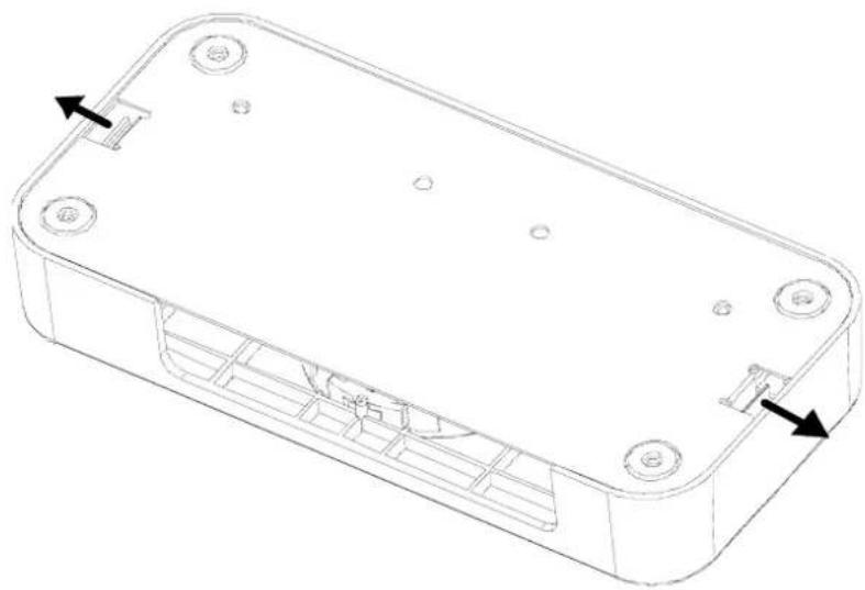
A Control board is located on the inside of the base unit. You can remove the cover PCB by pushing the hook of base unit.
natural_image
Technical line drawing of a rectangular electronic enclosure with mounting holes and internal compartments (no text or symbols)※ CAUTION
Make sure if the cover PCB is closed prior to power on
8-1 Serial Board
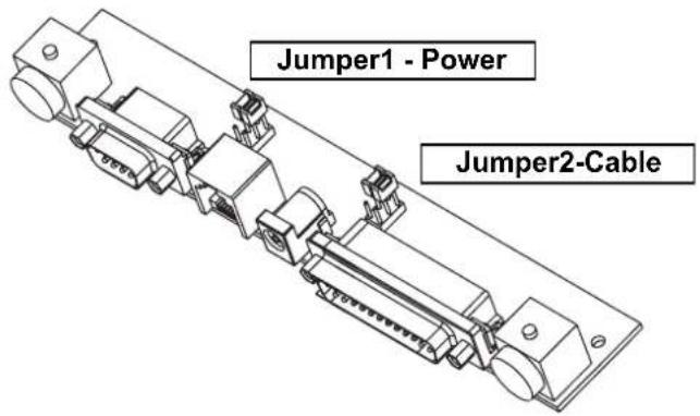

8-1-1 Jumper1
| Connection type JP1 Jack Type | |||
| Input Power (5~24VDC) 1-2 |  | Location J1 | |
| Input Power (24VDC) 2-3 |  | Location CN1 | |
| N/C | 4-5 | ||
| Out power to print(24VDC)(Pass through Type) | 5-6 |  | Location CN2 |
8-1-2 Jumper2
Some functions depend on the device's connection to the BCD-1000, such as whether a printer is connected or not with a data pass through connection, or stand alone connection.
| Connection type JP2 JP2 Function | |||
| Data pass though (default setting) | 1-2 | 4-5 | Can connect a printer which does not support the ESC = command. |
| Only SERIAL 2-3 | 5-6 No | printer is connected. | |
9. Appendix
9-1 Specifications
| Item Description | ||
| Display | Display Method VFD | |
| Brightness | 800~1000 [cd/m2] | |
| Character Size 5 x 7 [dot] | ||
| Number of Columns 20 character, 2 line | ||
| Operating Temperature | 0~45 °C | |
| Operating Humidity 10~80 % | ||
| Reliability | VFD 20,000 [hour] | |
9-2 Certification
1) EMC & Safety Standards
• Europe: CE EMC, TUV GS: EN60950-1: 2001
• North America: FCC Part 15 Subpart B
• Safety Standards: CB-scheme: IEC60950-1: 2001
WARNING
Use of an unprotected interface cable with this device conflicts with EMC standards. Users should only use cables approved by BIXOLON.
2) CE Mark
• EMC Directive 89/336/EEC
EN 55022:1994 +A1:1995 +A2:1997
EN 61000-3-2:2000
EN 61000-3-3:1995 +A1:2001
EN 55024:1998 +A1:2001
EN 61000-4-2:1995 +A1:1998 +A2:2001
EN 61000-4-3:1996 +A1:1998 +A2:2001
EN 61000-4-4:2004
EN 61000-4-5:1995 +A1:2001
EN 61000-4-6:1996 +A1:2001
EN 61000-4-11:1994 +A1:2001
- Low Voltage Directive 73/23/EEC Safety: EN60950-1:2001
3) WEEE (Waste Electrical and Electric Equipment)

This marking shown on the product or its literature, indicates that is should not be disposed with other household wastes at the end of its working life. To prevent possible harm to the environment or human health from uncontrolled waste disposal, please separate this from other types of wastes and recycle it responsibly to promote the sustainable reuse of material resources. Household users should contact either the retailer where they purchased this product, or their local government office, for details of where and how they can take this item for environmentally safe recycling. Business users should contact their supplier and check the terms and conditions of the purchase contract. This product should not be mixed with other commercial wastes for disposal.
9-3 Label Types
The label types used with this printer is as follows.
• BIXOLON Logo Labels: PET
- Rating Labels: PP
- Other Labels: PET
- User's Manual BCD-1000 Series
- ■ Safety Precautions
- WARNING
- Do not plug several products in one multi-outlet.
- You must use only the supplied adapter.
- Do not pull the cable to unplug.
- Keep the plastic bag out of children's reach.
- Do not plug in or unplug with your hands wet.
- Do not bend the cable by force or leave it under any heavy object.
- CAUTION
- Install the printer on the stable surface.
- Do not let water or other foreign objects in the Display.
- Table of Contents
- Complete Product Configuration....6
- Unpacking .... 7
- Defaults & Options by Product Type....9
- Connection Type & Size.... 11
- Function....13
- Connection .... 15
- Switches ...... 20
- Power Control 22
- Appendix ...... 24
- Complete Product Configuration
- NOTES
- Unpacking
- 2-2 BCD-1000DN Type
- 2-3 BCD-1000W Type
- 2-4 BCD-1000WN Type
- Defaults & Options by Product Type
- 3-1 Serial Type
- 3-1-2 Pass through Type
- Connection Type & Size
- 4-1 BCD-1000D Type
- 4-2 Size
- 4-2-1 Desk Top Type
- 4-2-2 Wall Mount Type
- 4-2-3 Etc.
- Function
- 5-1 Rotation
- 5-2 Angling
- Connection
- 6-1 Direct Type Pin Connection
- 6-1-1 Interface Specification
- 6-1-3 Installation Instructions
- 6-1-4 Signal Assignments (Cable-end DSUB)
- 6-1-5 DC Power Jack
- 6-2 Serial pin Connection
- 6-2-1 Host interface connector
- 6-2-2 Host interface connector signal assignments
- 6-2-3 Printer interface connector
- 6-2-4 Printer interface connector signal assignments
- Switches
- 7-1 Display Switch
- 7-2 DIP switches
- ※ CAUTION
- 7-3 Memory Switches
- Power Control
- 8-1 Serial Board
- 8-1-1 Jumper1
- 8-1-2 Jumper2
- Appendix
- 9-1 Specifications
- 9-2 Certification
- 3) WEEE (Waste Electrical and Electric Equipment)
- 9-3 Label Types
Brand : SAMSUNG
Model : BCD-1000DG
Category : Post Display