
SNMP Card for PDU RC-16A - Network card PowerPlus - Free user manual and instructions
Find the device manual for free SNMP Card for PDU RC-16A PowerPlus in PDF.


| Product Type | Network Card for PDU |
| Brand | PowerPlus |
| Model | SNMP Card for PDU RC-16A |
| Ethernet Interface | 10/100Base-T (RJ-45) |
| Supported Protocols | TCP/IP, UDP, SNMP, SMTP, SNTP, HTTP |
| Management Features | Embedded web server, SNMP MIB, PDUTracker software support |
| Monitoring | Real-time PDU data (input, output, environmental), event and data logs |
| Environmental Monitoring | Supports optional EMD (temperature and humidity sensor) |
| Logging | Event log and data log with export to CSV; daily reports |
| Installation | Slides into intelligent slot of compatible PDU, secured with screws |
| Default IP Address | 192.168.102.230 (DHCP auto or manual) |
| Default Password | 12345678 (administrator) |
| Sensor Port | For connecting environmental monitoring device |
| Power Source | Powered via PDU slot (no external power supply needed) |
| LED Indicators | Ethernet port status LEDs |
| Weight | Approx. 100 g |
| Dimensions | Approx. 100 x 70 x 20 mm |
Frequently Asked Questions - SNMP Card for PDU RC-16A PowerPlus
User questions about SNMP Card for PDU RC-16A PowerPlus
0 question about this device. Answer the ones you know or ask your own.
Ask a new question about this device
Download the instructions for your Network card in PDF format for free! Find your manual SNMP Card for PDU RC-16A - PowerPlus and take your electronic device back in hand. On this page are published all the documents necessary for the use of your device. SNMP Card for PDU RC-16A by PowerPlus.
USER MANUAL SNMP Card for PDU RC-16A PowerPlus
Management Software for Power Distribution Unit
Table of Contents
1. Overview.... 1
1.1 Introduction ...... 1
1.2 Features .... 1
1.3 Overlook.... 1
1.4 Installation and Connection .... 1
1.5 Configuration.... 2
1.6 Monitoring 3
2. PDU web card GUI 5
3. Function Menu 6
3.1 Information....6
3.2 PDU setting....6
3.3 Control 7
3.4. System configuration....9
3.5. Log 13
3.6. Help....14
1. Overview
1.1 Introduction
This PDU Web card can provide web server to monitor and manage multiple PDUs in a networked environment including LAN and INTERNET. It can detect temperature and humidity of the environment via connected EMD (Environmental Monitoring Device).
Integrated with PDUTracker software, it can monitor and remotely access to all distributed PDU web cards in a LAN or INTERNET. For the detailed operations, please check the user manual of PDUTracker.
1.2 Features
➢ Embedded web server via web browser
➢ Offer SNMP MIB to monitor PDU status.
➢ Support 10M/100M Fast Ethernet auto-detect function
Support protocols such as TCP/IP, UDP, SNMP, SMTP, SNTP, HTTP and so on.
➢ Support event log record and export, including PDU warnings, faults and EMD warnings.
➢ Support data log record and export.
➢ Support daily reports for event log and data log.
1.3 Overlook

① Ethernet port (10/100Base-T)
② Sensor port
③ Golden finger: connects to PDU slot
④ Ethernet port status LEDs
1.4 Installation and Connection
Installation
When using SNMP card, please follow the installation steps below first:
Step 1: Remove the cover of intelligent slot on the panel of PDU and retain the screws
Step 2: Slide the card into the slot and fix it with the screws from step 1. (See Chart 1-1)
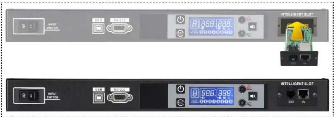
Chart 1-1
For system diagram of PDU web card, please refer to chart 1-2.
Plug the Ethernet cable to the Ethernet port (RJ-45) on the SNMP card. Use another Ethernet cable to connect to the sensor port on the SNMP card and the other end to the optional environmental monitoring device.
![graph TD A["Connects to Environmental Monitoring Device"] --> B["Router"] B --> C["SNMP"] D["User 1"] -->|LAN| B E["User 2"] -->|LAN| B F["User 3"] -->|LAN| B G["User 4"] -->|LAN| B H["User 5"] -->|LAN| B I["User 6"] -->|LAN| B J["User 7"] -->|LAN| B K["User 8"] -->|LAN| B L["User 9"] -->|LAN| B M["…](/content/2026/05/1074918/images/ad93182c99b09e5d334d7e1c163897238310b8746fcb5a8c4b3af3904e910fbd.jpg)
Chart 1-2
1.5 Configuration
a) Please install SNMP web manager in your PC. After software is installed successfully, a shortcut icon of the Installer will appear on your desktop as shown in Chart 1.4.
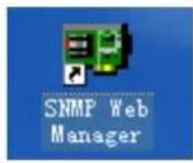
Chart 1-4
b) Enter specific IP address to search all of the SNMP devices in the LAN. The SNMP web manager will automatically collect the IP addresses from sever in default via a DHCP server. If there is no DHCP server, it will apply default IP address as 192.168.102.230, default subnet mask as 255.255.255.0 and default gateway 0.0.0.0.

Chart 1-5
c) User can modify IP setting, online upgrade, password management, and static trap address setting in SNMP Web Manager interface. It is necessary to enter password for any modifications. The default password is 12345678.
Please check SNMP Web Manager User Manual for detailed configuration.
1.6 Monitoring
There are two ways to monitor the device:
a) Double click the selected device from the device list (refer to Chart 1-5) and it will pop up screen as Chart 1-6.

Chart 1-6
b) Install PDUTracker software to monitor SNMP web card. Refer to Chart 1-7.
Please check PDUTracker User Manual for detailed operation.

Chart 1-7
2. PDU web card GUI
PDU web card GUI includes the function menu, login section and main screen. Refer to Chart 2-1:

Chart 2-1
A. PDU web card version
B. Function Menu
It offers complete tool-set for navigation and setting of the GUI.
C. Main Screen
It will display information and/or control alternatives according to the selected function menu.
D. Login section
It shows the current user type that logs in. The default passwords for administrator is "12345678".
3. Function Menu
3.1 Information
3.1.1. Status
Select Information >> Status. Please refer to Chart 3-1. It shows real-time monitored PDU data including input, output and environmental information in table format.

Chart 3-1
3.1.2. Basic information
Select Information>>Basic information. It includes PDU basic information and PDU rated information. Please refer to Chart 3-2.

Chart 3-2
3.2 PDU setting
3.2.1 Parameters setting
Some PDU parameters can be configured with PDU Web Server. Configurable parameter setting includes outlet setting, voltage and current range setting,
shutdown imminent time and Delay between turning on outlet. Select PDU setting >> Parameters setting. Please refer to Chart 3-4.

Chart 3-4
Step 1. Click "Apply" button to save the settings. Each function setting is saved by clicking "Apply" button in each section.
Step 2. Click "Default" button to recover the default setting.
Note: Any functions which are not supported by PDU will not be able to access.
➢ Maximum current ( A ): Setting maximum output current in Amp for each outlet. If output current is higher than this setting, PDU will alarm overload warning.
OFF at power on: When selected, there is no output on this outlet after PDU is turned on. If unclicked, it will have output on this outlet after PDU is turned on.
➢ Automatic disconnection: When selected, if overload warning happens, it will cut off power on selected outlet in one minute.
ON / OFF from the panel: When selected, it's allowed to manually turn on/off the selected outlet. When unclicked, it's not allowed to manually turn on/off the selected outlet.
Low input warning voltage: Setting low input warning voltage. When input voltage is lower than this setting point, it will buzz to remind users.
➢ High input warning voltage: Setting high input warning voltage. When input voltage is higher than this setting point, it will buzz to remind users.
Max. input voltage: Setting acceptable maximum input voltage point. When input voltage is higher than this setting point, it will buzz and
then shut down all outlets immediately.
Low input current: Setting acceptable low input current point. When input current is lower than this setting point, it will buzz to remind users
➢ High input current: Setting acceptable high input current point. When input current is higher than this setting point, it will buzz to remind users.
➢ Delay time to turn on outlet: Setting delay time for activating output outlet.
3.3 Control
3.3.1. Real-time control
Select Control >> Real-time control. Please refer to Chart 3-5.

Chart 3-5
You can real-time control the PDU by executing the following operations:
➢ PDU test: Before operation, please apply this test to check if all the panel LEDs and the buzzer are working well.
➢ Pre-alarm time before shutdown: Set pre-alarm time before shutting down the selected outlet.
Shut down # no. outlet in x minute(s): The selected outlets will be shut down in x minute(s).
Shut down # no. outlet in x minute(s) and restore in x minute(s): the selected outlets will be shut down in x minutes and turned on in x minute(s).
➢ Cancel shutdown # no. outlet: If the selected outlet is counting down for shutdown, this action will cancel the shutdown immediately.
3.4. System configuration
3.4.1. Web user
It configures the authority to access to SNMP web card. Please enter access ID and password in each column. There is no any limitation to access control in default setting. Please refer to Chart 3-6.
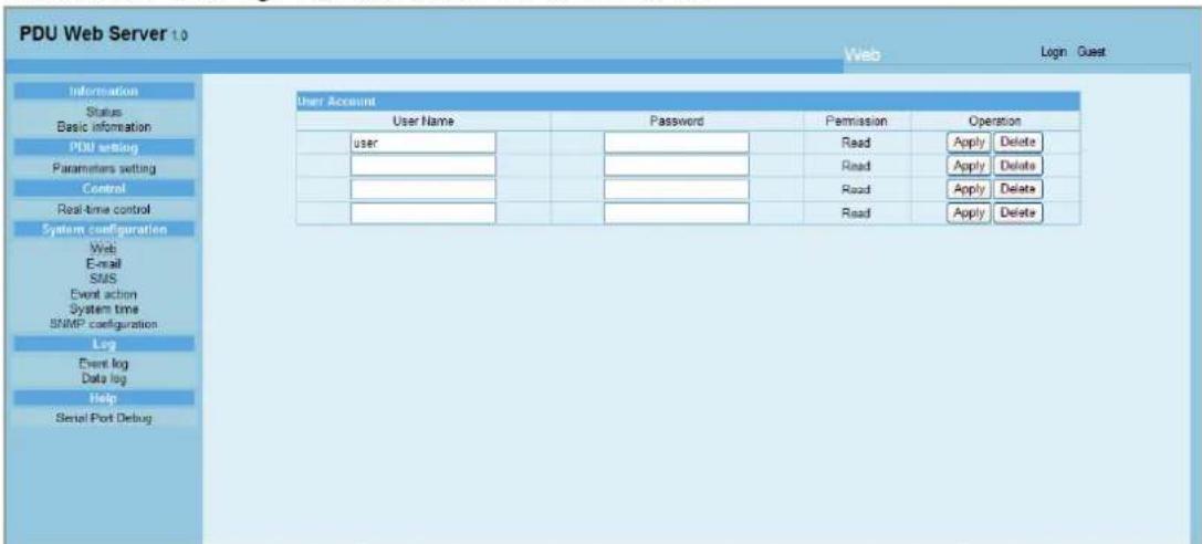
Chart 3-6
3.4.2. E-mail
It's allowed to send alarm mail from SMTP server. To use this function, the e-mail service must be correctly configured. All values in this function page are empty in default. This action can't be executed without the SMTP information, e-mail account and password. Besides, the sender account should be permitted for SMTP/POP3 forwarding.
Select System Configuration >> E-mail. Please refer to Chart 3-7

Chart 3-7
-
Enter SMTP server, SMTP port, sender's E-mail address, user name and password. Click the checkbox "Need Auth" for password verification.
-
Enter correct e-mail accounts in Receiver list. Then, click "Apply" to add them into receivers list. Click "Delete" button to delete them.
-
Click "Apply" to save the changes. The "Test" button can be used to send a test e-mail to all receivers to confirm the correct operation. When the test e-mails are successfully sent to the specific recipients, a successful dialog will pop up on the operated PC. Otherwise, a failure dialog will pop up to indicate there is an error for parameter setting.
-
You may decide who will receive daily report e-mail at designate duration. Please enter recipient's Email Address and timer into the corresponding columns. Then, click "Apply" button to set up this action. You also can configure who will receive the alarm e-mail when event log exceeds 100 or data log exceeds 50 records. Please click checkbox for selection.
3.4.3. SMS
It's required to have a service software such as ViewPower Pro to execute the function. If an alarm occurring, a message of the PDU status will be sent to the specified users via mobile phone. Please refer to Chart 3-8.

Chart 3-8
3.4.4. Event action
This function is available only integrated with Shutdown Wizard. Please also check the user manual of Shutdown Wizard for the details.
Select System Configuration >> Event action. Please refer to Chart 3-9.
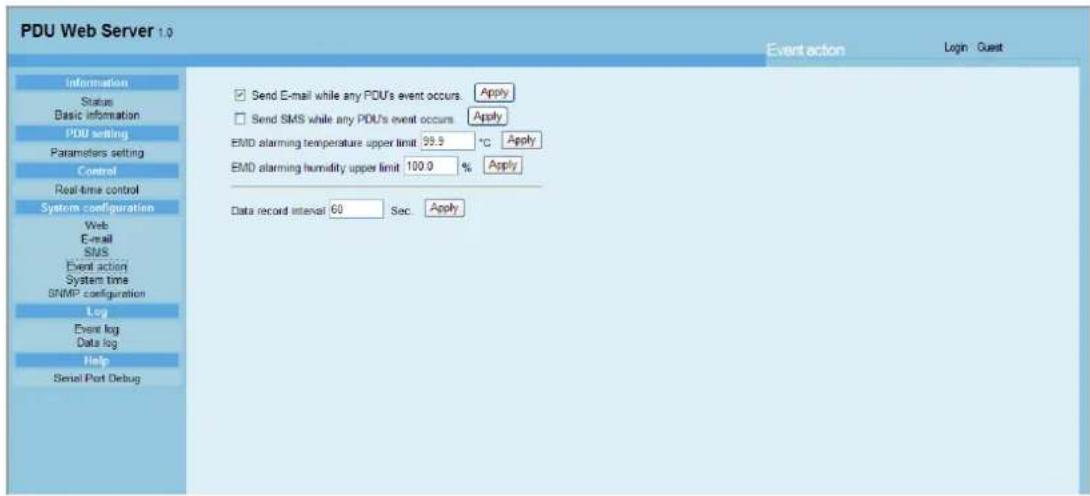
Chart 3-9
- Send an e-mail notification while any PDU event occurs: When clicking this checkbox, it will send an e-mail alarm when any event occurs on the local PDU.
- Send an SMS while any PDU event occurs: When clicking this checkbox, if an alarm occurs, a message of PDU status will be sent to the specified users via mobile phone.
- EMD alarms if temperature is over upper limit: Set up alarm for high temperature point. If detected temperature is beyond setting value, an alarm message will be sent.
- EMD alarms if humidity is over upper limit: Set up alarm for high humidity point. If detected humidity is beyond setting value, an alarm message will be sent.
● Data record interval xx sec: The data will be recorded in Data log per xx sec.
3.4.5. System time
Select System Configuration >> System time. Please refer to Chart 3-10.
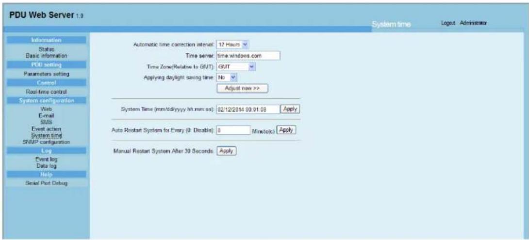
Chart 3-10
● Automatic time correction interval
● Time server: The SNTP server IP address or domain name.
● Time Zone (Relative to GMT)
- Applying daylight saving time
- System Time (mm/dd/yyyy hh:mm:ss): It is to set up SNMP web local host time
● Auto Restart system for Every (0: Disable): XX Minute(s)
- Manual Restart system after 30 Seconds: When click "Apply" button, SNMP will restart after 30 seconds.
3.4.6. SNMP configuration
Setting SNMP web card basic information such as set IP address, passwords, trap IP address, SNMP UDP port and restore to the default settings.
Note: It's normal to reboot after some operations are executed.
Select System Configuration >> SNMP configuration. Please refer to Chart 3-11.


Chart 3-11
● IP address: There are two methods to obtain IP address
- Automatically obtain IP address (DHCP, default)
- Manually configure IP address
The system will automatically obtain IP addresses in default. If there is no this kind of service provided in LAN, the default IP will display as "192.168.102.230", Net mask as "255.255.255.0" and default gateway as "0.0.0.0".
- Password: Modify the password. The required length of password is 8\~15 digits.
● Trap IP address: It provides 4 static trap addresses in the SNMP device.
● SNMP UDP port: You may change SNMP port and trap port. - Restore to the default settings
Note: The system will automatically obtain IP addresses in default and the default password is 12345678.
3.5. Log
3.5.1. Event log
In the Event Log window, history events are listed and can be saved as .csv file. The event log includes PDU warnings, fault info and EMD warnings. Please refer to Chart 3-12.
Select Log >> Event log.

Chart 3-12
3.5.2. Data Log
In the Data Log window, all history logs will be listed and can be save as .csv file. Please refer to Chart 3-13.
Select Log >> Data log.

Chart 3-13
3.6. Help
3.6.1. Serial Port Debug
It's to test communication condition between SNMP card and device.
Select Log >> Event log. Refer to Chart 3-14.

Chart 3-15
- TABLE OF CONTENTS
- OVERVIEW.... 1
- PDU WEB CARD GUI 5
- FUNCTION MENU 6
- OVERVIEW
- 1.1 INTRODUCTION
- 1.2 FEATURES
- 1.3 OVERLOOK
- 1.4 INSTALLATION AND CONNECTION
- INSTALLATION
- CHART 1-1
- 1.5 CONFIGURATION
- 1.6 MONITORING
- PDU WEB CARD GUI
- FUNCTION MENU
- 3.1 INFORMATION
- STATUS
- BASIC INFORMATION
- 3.2 PDU SETTING
- 3.2.1 PARAMETERS SETTING
- CHART 3-4
- 3.3 CONTROL
- REAL-TIME CONTROL
- CHART 3-5
- SYSTEM CONFIGURATION
- WEB USER
- SMS
- EVENT ACTION
- CHART 3-9
- SYSTEM TIME
- SNMP CONFIGURATION
- LOG
- EVENT LOG
- DATA LOG
- HELP
- SERIAL PORT DEBUG
Brand : PowerPlus
Model : SNMP Card for PDU RC-16A
Category : Network card