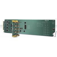
OG-3G-AM - Audio/video converter AJA - Free user manual and instructions
Find the device manual for free OG-3G-AM AJA in PDF.


| Product Type | Audio/Video Converter (3G-SDI Audio Embedder/Disembedder) |
| Model | OG-3G-AM |
| Brand | AJA |
| Video Input | 1 x 3G-SDI BNC (SMPTE-259/292/424) |
| Video Output | 1 x 3G-SDI BNC (SMPTE-259/292/424) |
| Audio Input | 4 x BNC (AES3, up to 8 channels) |
| Audio Output | 4 x BNC (AES3, up to 8 channels) |
| Supported Video Formats | 3G-SDI (Level A & B), HD-SDI, SD-SDI; up to 2048x1080p60 |
| Embedded Audio Channels | Up to 16 channels (24-bit, 48 kHz) |
| Audio Resolution | 24-bit |
| Embed Latency | 1500 µs (SRC ON), 400 µs (SRC OFF) |
| Disembed Latency | 210 µs |
| Control Interface | DIP switches (8-position) or USB via AJA Mini-Config software (PC/Mac) |
| Hot-Swap Capable | Yes |
| Compatibility | openGear frames DFR-8321 and OG3 |
| Power Consumption | 5.0 W max (per card) |
| Weight | 0.5 lb (227 g) |
| Operating Temperature | 0°C to 40°C (32°F to 104°F) |
| Storage Temperature | -40°C to 60°C (-40°F to 140°F) |
| Humidity | 10-90% non-condensing |
| Warranty | 5 years international |
| Safety Standards | FCC Class A, CE, ICES-003, etc. |
| Card Form Factor | openGear standard, occupies 2 slots |
| Rear Card Included | OG-10-BNC-Rear (10 x BNC) |
Frequently Asked Questions - OG-3G-AM AJA
User questions about OG-3G-AM AJA
0 question about this device. Answer the ones you know or ask your own.
Ask a new question about this device
Download the instructions for your Audio/video converter in PDF format for free! Find your manual OG-3G-AM - AJA and take your electronic device back in hand. On this page are published all the documents necessary for the use of your device. OG-3G-AM by AJA.
USER MANUAL OG-3G-AM AJA
Installation & Operation Guide
Version 1.0
Published: April 11, 2016

natural_image
Green printed circuit board with multiple electronic components and a yellow connector panel (no visible text or symbols)Table of Contents
Notices....4
Trademarks 4
Copyright 4
Contacting Support 4
Chapter 1: OG-3G-AM ....5
Card Overview 5
Features 5
OG-3G-AM Simplified Block Diagram 6
Connectors for
OG-3G-AM 6
Indicators....6
User Controls....7
DIP Switches 7
openGear and AJA 7
Parts Lists....7
Installation....7
Summary 7
Unpacking 8
Rear BNC Card Installation.... 8
Front Card Installation.... 8
Cabling 9
Chapter 2: Operation....10
Default Operational Settings.... 10
DIP Switches 10
DIP Switch Settings 11
Switch 6 Embedded Channel Mapping 12
Switch 7 Disembedding Channel Mapping.... 13
USB Control and Setup—Using AJA Mini-Config.... 13
Acquiring Mini-Config.... 13
Mini-Converter Documentation 13
Installing Mini-Config 14
PC Installation 14
Mac Installation.... 15
Running Mini-Config 15
PC Startup.... 16
Mac Startup 16
Saving Setups 16
Operating Mini-Config 16
Running Multiple Mini-Converters.... 17
Tabbed Screens.... 18
Audio-1 Screen.... 18
Audio-2 Screen....19
Update Screen 21
Software Update Procedure.... 21
Info Screen 22
Appendix A: Specifications .....23
Video Input 23
Input Formats.... 23
Video Output 23
Output Formats.... 23
Audio Inputs and Outputs 24
User Controls.... 24
Physical 24
Appendix B: Safety and Compliance....25
Federal Communications Commission (FCC) Compliance Notices 25
Class A Interference Statement 25
FCC Caution 25
Canadian ICES Statement.... 25
European Union and European Free Trade Association (EFTA)
Regulatory Compliance.... 26
Declaration of Conformity.... 26
Recycling Notice 27
Korean KCC Compliance Statement 27
Taiwan Compliance Statement 27
Japanese Compliance Statement 27
Translated Warning and Caution Messages.... 28
Before Operation Please Read These Instructions 28
Warranty Information....36
Limited Warranty.... 36
Index....37
Trademarks
AJA® , Io® , Ki Pro ® , KONA ® , KUMO ® , T-TAP ® , Because it matters. ® and ROI ® are registered trademarks of AJA Video Systems, Inc. in the United States. AJA and Ki Pro are trademarks of AJA Video Systems, Inc. registered in other countries. AJA Control Room™, CION™, Corvid Ultra™, FiDO™, Science of the Beautiful™, TruScale™, TruZoom™, V2Analog™ and V2Digital™ are trademarks of AJA Video Systems, Inc.
AirPort, Apple, Apple logo, AppleShare, AppleTalk, FireWire, iPod, iPod touch, Mac and Macintosh are registered trademarks of Apple Inc. FinalCut Pro, QuickTime and QuickTime logo are trademarks of Apple Inc.
Avid, Avid DNxHD and Media Composer are registered trademarks of Avid Technology, Inc.
HDMI, the HDMI logo and High-Definition Multimedia Interface are trademarks or registered trademarks of HDMI Licensing, LLC.
DVI is a registered trademark of DDWG.
TASCAM is a registered trademark of TEAC Corporation.
Dolby ® and the double-D Dolby logo are registered trademarks of Dolby Laboratories Licensing Corporation.
openGear ® Ross, ROSS, ROSS ® , and MLE are registered trademarks of Ross Video.
Dashboard Control System™ is a trademark of Ross Video.
All other trademarks are the property of their respective holders.
Copyright
Copyright © 2015 AJA Video Systems, Inc. All rights reserved. All information in this manual is subject to change without notice. No part of the document may be reproduced or transmitted in any form, or by any means, electronic or mechanical, including photocopying or recording, without the express written permission of AJA Video Systems, Inc.
Contacting Support
When calling for support, have all information at hand prior to calling.
To contact AJA for sales or support, use any of the following methods:
Telephone: +1.530.271.3190
FAX:+1.530.271.3140
Web: http://www.aja.com
Support Email: support@aja.com
Sales Email: sales@aja.com
Chapter 1: OG-3G-AM

Card Overview
The OG-3G-AM is a triple rate 8 channel AES audio embedder/disembedder. AES audio can be embedded and disembedded simultaneously. The embedder is user selectable, on a channel pair basis, to either "pass" existing SDI input audio or embed AES input audio through the back panel. The ability to pass incoming ancillary data makes it possible to embed up to 16 channels of audio by cascading two units. Horizontal ancillary data (HANC) packets in compliance with SMPTE 291M can also be dropped at the input.
The OG-3G-AM automatically detects and configures to the input video standard. 3G-SDI formats up to and including 2048x1080p 60 YCbCr 4:2:2 are supported (see "Appendix A: Specifications on page 23" for a complete listing). The SDI output has minimal video latency and supports up to 16 channels of embedded audio.
NOTE: 2048x1080p/psf 29.97 and 30 formats support a maximum of 8 channels embedded audio.
Using the Mini-Config application, you can configure data packets to be passed from the AES inputs to embedded ancillary packets un-altered. This, along with minimized embed/disembed latency, ensures 100 percent compatibility with Dolby® bitstreams and other non-PCM data.
Features
- Triple rate 3G, HD, and SD-SDI embedder/disembedder
• 8 Channel AESI/O - 1 x BNC 3G-SDI input
- 1 x BNC 3G-SDI output
- 4 x BNC AES input
- 4 x BNCAES output
-
Setup via DIP switch or PC/Mac using USB port and supplied USB cable (Mini-Config configuration software application available via download from AJA website)
-
Hot-swap capable
- Compatible with DFR-8321 and OG3 openGear frames
- Five-year international warranty with unlimited technical support
NOTE: OG-3G-AM cards do not communicate with the Dashboard Control System.
OG-3G-AM Simplified Block Diagram
Figure 1. OG-3G-AM Block Diagram

flowchart
graph TD
    A["3G-SDI In"] --> B["EQ"]
    B --> C["Embed and Pass-through Packet Processor"]
    C --> D["Cable Driver"]
    D --> E["3G-SDI Out"]
    F["AES Input 1/2"] --> G["SRC"]
    H["AES Input 3/4"] --> I["SRC"]
    J["AES Input 5/6"] --> K["SRC"]
    L["AES Input 7/8"] --> M["SRC"]
    N["USB Port (connect to PC or Mac)"] --> O["MiniConfig"]
    P["DIP Switch User Interface"] --> Q["Control"]
    G --> R["Dis-Embedder"]
    I --> R
    K --> R
    M --> R
    R --> S["AES Output 1/2"]
    R --> T["AES Output 3/4"]
    R --> U["AES Output 5/6"]
    R --> V["AES Output 7/8"]
Connectors for OG-3G-AM
Figure 2. Rear View of OG-3G-AM Card Connectors

Indicators
LEDs on the front (near door) of the card indicate the presence of power and the type of signal detected on the SDI input as follows (from top to bottom):
- PWRLED illuminates green if DC power is detected.
- HD LOCK LED illuminates green if the input is 1.483Gbps or 1.485Gbps SDI.
- SD LOCK LED illuminates green if the input is 270Mbps SDI.
- Both HD LOCK and SD LOCK LEDs illuminate green if the input is 2.966Gbps or 2.970Gbps SDI.
User Controls
DIP Switches
The OG-3G-AM has an 8 position DIP switch accessible on the card. The DIP switches are used to configure the unit's audio embedding and disembedding, and control ancillary data.
Figure 3. OG-3G-AM DIP Switches

Factory default switch settings are all in the leftmost position.
The exact functions of the DIP switches are described in "Operation" on page 10.
openGear and AJA
openGear is an open-architecture, modular frame system designed by Ross Video and supported by a diverse range of terminal equipment manufacturers, including AJA. Ross Video manufactures the frames, power supplies and network cards for openGear.
AJA Video is a leading manufacturer of video interface technologies, converters, digital video recording solutions and professional cameras, bringing high-quality, cost-effective products to the professional, broadcast and post-production markets. AJA products, including openGear cards, are designed and manufactured at our facilities in Grass Valley, California.
Parts Lists
| Quantity Description | |
| 1 OG-3G-AM | Front Card in ESD bag |
| 1 BNC Rear Card | |
Installation
Summary
Installing an OG-3G-AM card into a DFR-8321 or OG3 openGear frame consists of the following steps:
• Install the Rear BNC Card into the frame,
- insert the Front DA Card in the right (even numbered) slot of the pair,
- connect the BNC cabling.

ESD Susceptibility - Static discharge can cause serious damage to sensitive semiconductor devices. Avoid handling circuit boards in high static environments such as carpeted areas, and when wearing synthetic fiber clothing. Always exercise proper grounding precautions when working on circuit boards and related equipment.
Unpacking
Unpack each openGear product you received from the shipping container and ensure that all items are included. If any items are missing or damaged, contact your sales representative or AJA directly.
Rear BNC Card Installation
- Power down the openGear frame.
- Ensure that the frame is properly installed.
- Locate the card frame slot on the rear of the openGear frame into which you wish to install the openGear card.
NOTE: An OG-3G-AM card occupies two slots in the frame.
- Using a Phillips screwdriver, unscrew the top screw from the desired blank rear plate and remove the rear plate.
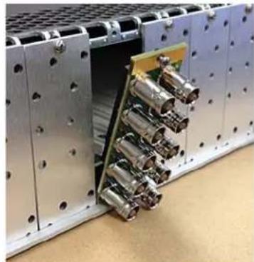
- Seat the bottom of the Rear Card in the seating slot at the base of the frame back plane (Figure 4).
Figure 4. Rear Card Inserted Into Frame Seating Slot
natural_image
Interior view of an electronic device module with metallic components and a green circuit board (no visible text or symbols)- Align the top screw of the Rear Card with the screw hole on the top edge of the frame back plane.
- Ensure the Rear Card aligns with the desired card slot before tightening the screw.
- Using a Phillips screwdriver, fasten the Rear Card to the frame back plane. Do not over tighten.
- Ensure proper frame cooling and ventilation by having all rear frame slots covered with rear modules or blank metal plates if plates are not pre-installed.
Front Card Installation
- Open the openGear frame door as follows:
A. Gently pull the side door tabs towards the center of the door, releasing the door from the frame.
B. Using both hands, pull the door towards you. The door extender arms prevent the door from falling.
-
Locate the Rear Card you installed as described above. The interior slot number is dependent on the slot combinations into which you installed the Rear Card. This allows adequate spacing to avoid damaging the card, the cards installed in the neighboring slots, or both.
-
Hold the card by the edges and carefully align the card edges with the rails inside the frame. The slots are numbered starting from the left-most slot when facing the fame front.
NOTE: OG-3G-AM cards are installed into the right (even numbered) slot of the pair.
- Fully insert the card into the frame until the card is properly seated in the Rear Card. (Figure 5).
Figure 5. Front Card Inserted Into Slot

natural_image
Interior view of a server rack with metal racks and a green panel, no visible text or symbols- Close the frame door as follows:
A. Slide the door into the frame.
B. Pull and release the door tabs to ensure the frame door is securely locked to the frame.
Cabling
Refer to Figure 2 on page 6 to identify the input and output signal connectors.
Chapter 2: Operation
Default Operational Settings
The OG-3G-AM ships from the factory with the following configuration:
- Local (DIP switch) control.
- Input AES audio channel pairs 1/2, 3/4, 5/6, 7/8 are embedded to SDI output channel pairs 1/2, 3/4, 5/6, 7/8, overwriting any existing embedded audio.
- Input SDI embedded audio channel pairs 1/2, 3/4, 5/6, 7/8 are disembedded to AES audio output channels 1/2, 3/4, 5/6, 7/8.
- All HANC packets pass from SDI input to output, except for embedded output audio channels 1/2, 3/4, 5/6, 7/8.
If these settings apply to your requirements, you can simply connect the video and audio input and output signal cables and power up the unit.
For other applications, you can configure the card using its DIP switch settings, or by using the Mini-Config application and a PC or Mac via USB.
DIP Switches
The OG-3G-AM DIP switches configure the audio embedding and disembedding functions, and control ancillary data.
Figure 4. OG-3G-AM DIP Switches

DIP Switch Settings
DIP switch settings used to configure various functions are described below.
Table 3. OG-3G-AM DIP Switch Setting Descriptions
| SWITCH | FUNCTION | DIP Set LEFT (default) | DIP Set RIGHT |
| 1 | Control | Selects Local (DIP), and blocks Mini-Config control. | Selects Remote (Mini-Config), and disables DIP switches 2-8. |
| 2 Audio Embedding for Channels 1/2 (EMBD 1/2) | (ON) Overwrite or embed new channel 1/2 packets. | (OFF) If AUX (SW 8) is ON: Pass any channel 1/2 packets from input SDI.If AUX (SW 8) is OFF: Delete all packets from input SDI. | |
| 3 Audio Embedding for Channels 3/4 (EMDB 3/4) | (ON) Overwrite or embed new channel 3/4 packets. | (OFF) If AUX (SW 8) is ON: Pass any channel 3/4 packets from input SDI.If AUX (SW 8) is OFF: Delete all packets from input SDI. | |
| 4 Audio Embedding for Channels 5/6 (EMDB 5/6) | (ON) Overwrite or embed new channel 5/6 packets. | (OFF) If AUX (SW 8) is ON: Pass any channel 5/6 packets from input SDI.If AUX (SW 8) is OFF: Delete all packets from input SDI. | |
| 5 Audio Embedding for Channels 7/8 (EMDB 7/8) | (ON) Overwrite or embed new channel 7/8 packets. | (OFF) If AUX (SW 8) is ON: Pass any channel 7/8 packets from input SDI.If AUX (SW 8) is OFF: Delete all packets from input SDI. | |
| 6 Channel | Mapping For Embedded Groups (EMBD GRP) | Embed to Groups 1/2 as specified in 272M and 299M | Embed to Groups 3/4 as specified in 272M and 299M |
| Refer to Table 4, "DIP SW 6 Embedded Channel Mapping," on page 12 | |||
| 7 Channel | Mapping For Disembedding Groups (DISEMBD GRP) | Disembed from Groups 1/2 as specified in 272M and 299M) | Disembed from Groups 3/4 as specified in 272M and 299M |
| Refer to Table 5, "DIP SW 7 Disembedded Input Channel Mapping," on page 13 | |||
| 8 Pass or Drop HANC input packets. (PASS HANC) | (ON) All incoming HANC packets are passed unless the embedder settings above require all or part of them to be over-written. | (OFF) All incoming HANC packets are dropped before embedding any new audio packets.Embedder settings above determine all embedded audio output.Disembedding is not affected. | |
NOTE: 2048x1080p/psf 29.97 and 30 formats support a maximum of 8 channels of embedded audio. When one of these formats is present and embedding is turned on, the PASS HANC DIP switch will be ignored and all incoming packets will be dropped before embedding any new audio packets.
Switch 6 Embedded Channel Mapping
The following table shows how switch 6 affects embedded channel mapping.
Table 4. DIP SW 6 Embedded Channel Mapping
| DIP SW 6EMBD GRP | AES Input Channel | SDI Embedded Group | SDI Embedded Output Channel |
| Left (1/2) 1 —> 1 | 1 | ||
| 2 —> 2 | |||
| 3 —> 3 | |||
| 4 —> 4 | |||
| 5 —> 2 5 | |||
| 6 —> 6 | |||
| 7 —> 7 | |||
| 8 —> 8 | |||
| Right (3/4) 1 —> 3 9 | |||
Switch 7 Disembedding Channel Mapping
The following table shows how switch 7 affects disembedding channel mapping.
Table 5. DIP SW 7 Disembedded Input Channel Mapping
| DIP SW 7 DISEMBD GRP | SDI Embedded Input Group | SDI Embedded Input Channel | AES Output Channel |
| Left (1/2) 1 1 —> 1 | |||
| 2 —> 2 | |||
| 3 —> 3 | |||
| 4 —> 4 | |||
| 2 5 —> 5 | |||
| 6 —> 6 | |||
| 7 —> 7 | |||
| 8 —> 8 | |||
| Right (3/4) 3 9 —> 1 | |||
| 10 —> 2 | |||
| 11 —> 3 | |||
| 12 —> 4 | |||
| 4 13 —> 5 | |||
| 14 —> 6 | |||
| 15 —> 7 | |||
| 16 —> 8 |
USB Control and Setup—Using AJA Mini-Config
Your AJA openGear card can be used with its default configuration settings for some applications since it is designed to recognize inputs and perform standard actions automatically by default. However, to use its full capability, you must use AJA's Mini-Config software application for PCs and Macs. This same application can be used to update to new Mini-Converter software released by AJA.
NOTE: DIP switch 1 must be ON (Remote, Right) to permit Mini-Config control of the unit.
Connecting the USB Cable to the USB Port on the OG-3G-AM Card
Connect the USB cable to the USB port located on the front of the OG-3G-AM card, as shown in "Figure 5. OG-3G-AM USB Port on page 14".
Figure 5. OG-3G-AM USB Port

Acquiring Mini-Config
AJA's Mini-Config application is available for download from the AJA website.
To download the latest Mini-Config package, which includes the Mini-Config application, Mini-Converter firmware, and documentation, go to:
https://www.aja.com/en/products/mini-converters/mini-config-software
Select either the Windows or Mac icon to download the desired version.
Mini-Converter Documentation
Included with the Mini-Config package is a complete set of documentation for all Mini-Converters supported by Mini-Config. A .PDF of the Installation and Operation Guide for the currently connected Mini-Converter can be accessed from the Mini-Config UI via the Help/Manual drop-down menu.
Documentation for all AJA Mini-Converters that use Mini-Config can also be accessed directly in the Mini-Config download package Documentation folder, and via the Documentation icon available on the Mac installer.
Documentation (and firmware) included with the Mini-Config application are the versions available at the time of distribution. However, Mini-Converter software, firmware and documentation are updated regularly, so newer versions may exist.
To download the latest documentation for an individual Mini-Converter, go to:
https://www.aja.com/en/category/mini-converters
and navigate to the Support webpage of that Mini-Converter.
Installing Mini-Config
PC Installation To install Mini-Config on a Windows PC:
- Download the application from the AJA website (select the Windows icon on the Mini-Config Support webpage).
- Open the AJA_MiniConfig.zip file
- Double-click on the MiniInstaller.msi file.
- A Setup Wizard will guide you through the installation.
Figure 6. Mini-Config PC Setup Wizard

- Click Next to begin. Answer the questions in the subsequent dialogues. When finished, an AJA Mini-Config shortcut will be installed on the desktop, and you will be able to locate the Mini-Config application in the AJA folder in the Programs listing.
NOTE: If the Mini-Config application already exists on the PC, a different Setup Wizard appears.
Figure 7. Mini-Config Setup Wizard, Reinstallation
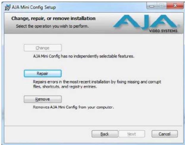
With this screen you can Repair (reinstall) or Remove (uninstall) Mini-Config on the PC.
Mac Installation To install the application on a Mac:
NOTE: Macintosh computers must be Intel-based (G5, G4 and earlier models will not work with Mini-Config).
- Download the application from the AJA website (select the Apple icon on the Mini-Config Support webpage).
- Open the AJA_MiniConfig folder.
- Double-click on the AJAMiniConfig.dmg file.
- Answer the prompt and a utility program will be launched.
Figure 8. Mini-Config Mac Installer

- To complete the installation drag the "MiniConfig.app" icon to the Applications folder.
Running Mini- Config
Connect the Mini-Converter to the PC or Mac via the supplied USB cable. Connect the external power supply (supplied) to the Mini-Converter.
PC Startup
To run Mini-Config on a PC, double-click on the AJA Mini-Config icon on your desktop, or open the AJA folder in the program list and click on the AJA Mini-Config application located inside the Mini-Config folder.

Mac Startup
To run Mini-Config on a Mac, open the Applications folder and locate the AJA Mini-Config application. Double-click the application to launch it.
Saving Setups
A File drop down menu on the Mini-Config application bar allows you to save the current state of the Mini-Converter to a preset file for later recall.
| MiniConfig | File | Edit | Help |
| Open Preset... | %O | ||
| Save Preset As... | %S | ||
| Revert to Factory Settings | |||
| Refresh | %R | ||
Using this feature you can set up the converter for different applications, storing each configuration (Save Preset As...) with a unique name for easy recall (Open Preset...).
A Revert to Factory Settings menu item similarly allows you to change the settings back to AJA's factory defaults.
Operating Mini- Config
The Mini-Config application provides a graphic interface for viewing settings and updating software. It consists of an information area at the top that shows the available Mini-Converters attached to the computer via USB, with a graphical rendering of the selected Mini-Converter showing all the connectors and their current state.
Colored text next to the connectors indicates the signal type and what the MiniConverter is doing:
- Blue text indicates the values automatically selected
- Black text indicates values that you have manually selected
- Red text indicates the Mini-Converter is not detecting a signal, or cannot operate with the current user settings.
NOTE: Even if no output device is detected, the SDI connector text still shows the signal it is outputting.
NOTE: Configuration settings in red will change based on the attached output device as well as input signals. For improved accuracy and reliability, you should configure the Mini-Converter only when the target output device is attached and input signals are supplied at the inputs.
Screens are virtually the same on both PC and Mac, with subtle differences that reflect the general look of the platform environment.
Running Multiple Mini-Converters
Mini-Config can manage multiple AJA Mini-Converters connected via USB—even when they are of differing types. However it only connects to one at a time. You can choose which Mini-Converter you wish to control using the pulldown menu in the upper right hand corner. If you want to configure multiple Mini-Converters in parallel, you can do it by running multiple instances of the Mini-Config application and have each control a different Mini-Converter.
NOTE: During a Mini-Converter firmware update, only one Mini-Converter should be connected to the computer via USB.
NOTE: The version 1.0 Mini-Config user interface displays an image of the 3G-AM Mini-Coverter, which has the same feature set as the OG-3G-AM card.
Figure 9. Example Mini-Config Screen

flowchart
graph TD
    A["Select a USB port and an attached Mini-Converter (name in parentheses)"] --> B["Port:1 (OG-3G-AM)"]
    B --> C["1080i29.97 Grp1 Grp2 Grp3 Grp4"]
    C --> D["HD/SD"]
    D --> E["Embed and Passthrough Packet Processor"]
    E --> F["1080i29.97 Grp1 Grp2 Grp3 Grp4"]
    D --> G["AES In Ch1/2"]
    D --> H["AES In Ch3/4"]
    D --> I["AES In Ch5/6"]
    D --> J["AES In Ch7/8"]
    E --> K["DIS-Embedder"]
    K --> L["AES Out Ch1/2"]
    K --> M["AES Out Ch3/4"]
    K --> N["AES Out Ch5/6"]
    K --> O["AES Out Ch7/8"]
    P["The input and output are labeled with the signals currently detected or manually selected."] --> Q["USB"]
    Q --> R["Controller"]
    R --> S["OTA"]
    S --> T["Audio-1 Audio-2 Update Info"]
    T --> U["Serial Number"]
    V["Firmware version"] --> W["OG-3G-AM"]
    W --> X["Tabbed screens"]
    X --> Y["AES Audio Inputs Embed to: Groups 1/2"]
    X --> Z["Ch 1/2 Embed: On"]
    X --> AA["Ch 3/4 Embed: On"]
    X --> AB["Ch 5/6 Embed: On"]
    X --> AC["Ch 7/8 Embed: On"]
    AD["Message Showing Status"] --> AE["Connected to module"]
Selecting a Mini-Converter with the pulldown menu causes this application to connect to the selected converter. The graphic of Mini-Converter and text below it provides:
- Type of converter
- Firmware version
- Serial number of the unit.
A status field at the bottom of the screen shows if your application is connected and communicating with the Mini-Converter.
When configuring the Mini-Converter, select it from the top pulldown, view the current settings and change any values. Making a change communicates that new value to the Mini-Converter's non-volatile memory.
Tabbed Screens
The Tabs delineate control screens with groups of controls for each type of task to be performed.
The controls for the actual configuration parameters are specific to each Mini-Converter type. When you Click on any of the tab buttons, the pane below the tabs will change to match your tab selection. Any changes you make are immediately applied and will be saved, overwriting previous settings.
Audio-1 Screen

flowchart
graph TD
    A["1080i29.97 Grp1 Grp2 Grp3 Grp4"] --> B["HD SD"]
    B --> C["Embed and Passthrough Packet Processor"]
    C --> D["Dis-Embedder"]
    E["AES In Ch1/2"] --> F["SRC: Auto"]
    G["AES In Ch3/4"] --> H["SRC: Auto"]
    I["AES In Ch5/6"] --> J["SRC: Auto"]
    K["AES In Ch7/8"] --> L["SRC: Auto"]
    M["USB"] --> N["Controller"]
    O["1080i29.97 Grp1 Grp2 Grp3 Grp4"] --> P["AES Out Ch1/2"]
    Q["AES Out Ch3/4"] --> R["AES Out Ch5/6"]
    S["AES Out Ch7/8"] --> T["AES Out Ch7/8"]
Click on the Audio-1 tab to view and make changes to the audio embedding and disembedding settings.
AES Audio Inputs
Embed to: Choose which SDI embedded audio groups will embed incoming AES audio: • Groups 1/2 (Ch 1-8), or Groups 3/4 (Ch 9-16).
Ch1-2 Embed: On embeds AES audio Ch 1/2 pair in the first two channels of the Groups selected above.
Ch 3-4 Embed: On embeds AES audio Ch 3/4 pair in the next two channels of the Groups selected above.
Ch 5-6 Embed: On embeds AES audio Ch 5/6 pair in the next two channels of the Groups selected above.
Ch 7-8 Embed: On embeds AES audio Ch 7/8 pair in the last two channels of the Groups selected above.
AES Audio Outputs
Disembed from: Choose which SDI embedded audio group will disembed its audio and send it to the four AES audio outputs:
• Group 1/2 (Ch 1-8), Group 3/4 (Ch 9-16).
Audio-2 Screen
flowchart
graph TD
    A["1080i29.97 Grp1 Grp2 Grp3 Grp4"] --> B["HD SD"]
    B --> C["Embed and Passthrough Packet Processor"]
    C --> D["Dis-Embedder"]
    D --> E["AES Out Ch1/2"]
    D --> F["AES Out Ch3/4"]
    D --> G["AES Out Ch5/6"]
    D --> H["AES Out Ch7/8"]
    I["AES In Ch1/2"] --> J["SRC: Auto"]
    K["AES In Ch3/4"] --> L["SRC: Auto"]
    M["AES In Ch5/6"] --> N["SRC: Auto"]
    O["AES In Ch7/8"] --> P["SRC: Auto"]
    Q["Controller"] --> R["USB"]
    S["Packet Processing Control"] --> T["HANC Data: Pass"]
    U["3G-SDI Level B: Stream A"] --> V["Sync SRC Ch1/2: Auto"]
    V --> W["Sync SRC Ch3/4: Auto"]
    W --> X["Sync SRC Ch5/6: Auto"]
    X --> Y["Sync SRC Ch7/8: Auto"]
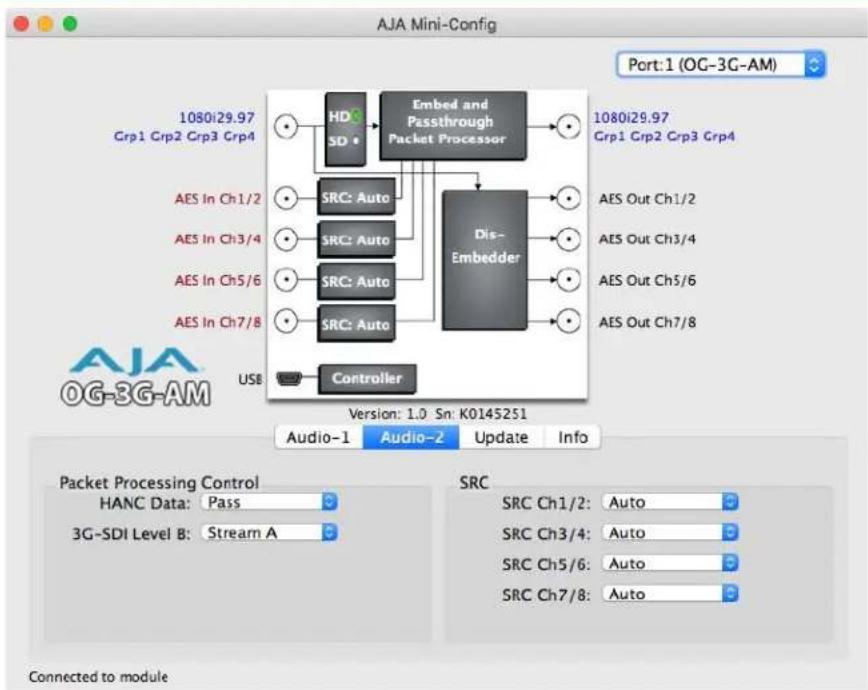
Click on the Audio-2 tab to view and make changes to the packet processing and audio level settings.
Packet Processing Control
HANC Data: When Pass is selected, all incoming HANC packets are passed unless the embedder settings require all or part of them to be over-written.
When Remove is selected, all incoming HANC packets are dropped before embedding any new audio packets. The embedder settings determine all embedded audio output. Disembedding is not affected.
NOTE: 2048x1080p/psf 29.97 and 30 formats support a maximum of 8 channels of embedded audio. When one of these formats is present and embedding is turned on, the PASS HANC setting will be ignored and all incoming packets will be dropped before embedding any new audio packets.
3G-SDI Level B: For 3G Level B signals, this control selects either the 16 audio channels of input Stream A or the 16 channels of input Stream B for disembedding. This setting also controls whether output Stream A or output Stream B will receive embedded audio. This control has no effect if a 3G Level B signal is not detected.
SRC This setting determines whether AES audio inputs are passed through the sample rate converter before embedding. Turn this setting Off for compatibility with non-PCM bitstreams such as Dolby-E or Dolby-B.
Choose Auto, On, or Off for each of the indicated input channel pairs: (Ch 1/2, Ch 3/4, Ch 5/6, Ch 7/8).
- Auto - Automatically selects whether incoming AES audio is sample rate converted. If channel status bits are detected that indicate the audio is PCM (normal digital audio), the audio will be passed through the sample rate converter. If compressed audio (such
as Dolby) bits are detected, the sample rate converter is bypassed (it would corrupt the compressed data).
- On - Pass all input AES audio through the sample rate converter before embedding (for example, for use with PCM audio). AES inputs are sample rate converted to a 48KHz rate synchronous to the video input.
- Off - Do not pass any input AES audio through the sample rate converter before embedding (for example, for use with Dolby® Digital from a synchronous source).
NOTE: For proper operation with SRC Off, the AES input timing must be externally synchronized to the input SDI.
About SRC Settings
48KHz synchronous ancillary packets are disembedded and passed unaltered to the AES outputs regardless of the SRC setting. With the SRC setting Off, data packets are passed from the AES inputs to embedded ancillary packets un-altered, according to SMPTE 337M. All AES3-2003 defined channel status bits are passed through unaltered in both the embed and dis-embed directions—except for the sample rate field, which is always set to 48KHz. The channel status CRC is re-calculated and inserted into the bitstream. This ability, along with a very small audio embed/disembed latency, ensures 100 percent compatibility with Dolby® bitstreams.
Update Screen

flowchart
graph TD
    A["1080i29.97 Grp1 Grp2 Grp3 Grp4"] --> B["HD SD"]
    B --> C["Embed and Passthrough Packet Processor"]
    C --> D["Dis-Embedder"]
    E["AES In Ch1/2"] --> F["SRC: Auto"]
    G["AES In Ch3/4"] --> H["SRC: Auto"]
    I["AES In Ch5/6"] --> J["SRC: Auto"]
    K["AES In Ch7/8"] --> L["SRC: Auto"]
    M["USB"] --> N["Controller"]
    O["1080i29.97 Grp1 Grp2 Grp3 Grp4"] --> P["AES Out Ch1/2"]
    Q["AES Out Ch3/4"] --> R["AES Out Ch5/6"]
    S["AES Out Ch7/8"] --> T["AES Out Ch7/8"]
Use this Update screen to view the software version currently installed on the converter or install new software.
NOTE: When discussing Mini-Converters, "Firmware" is software that will be stored in the Mini-Converter's non-volatile memory and used when it is powered up. This is something different than the Mini-Config application software. The version numbers shown in the Update screen refer only to the firmware.
The following fields and control are present in this screen:
Installed: This field shows the version of the firmware currently installed inside the Mini-Converter.
Desired: This field shows the version of firmware embedded in the Mini-Config application which you can install into the Mini-Converter by clicking the Update button.
Update This button initiates a software update operation loading the "Desired" version of firmware into the Mini-Converter's non-volatile memory.
Progress: This indicator bar shows the progress of software being installed.
Software Update Procedure
- Check the AJA website for new Mini-Config software for your Mini-Converter. If new software is found, download it and uncompress the file archive (zip). Here is the URL to use when checking:
http://www.aja.com/en/products/mini-converters/mini-config-software
-
Connect the Mini-Converter to a Mac or PC via a USB port on the computer and run the new Mini-Config software just downloaded.
-
Click on the Update tab screen.
-
Check the Installed version level against the Desired version level. If the Desired is newer, then click the Update button to download the new firmware to the MiniConverter; progress will be shown via the "Progress" thermometer bar.
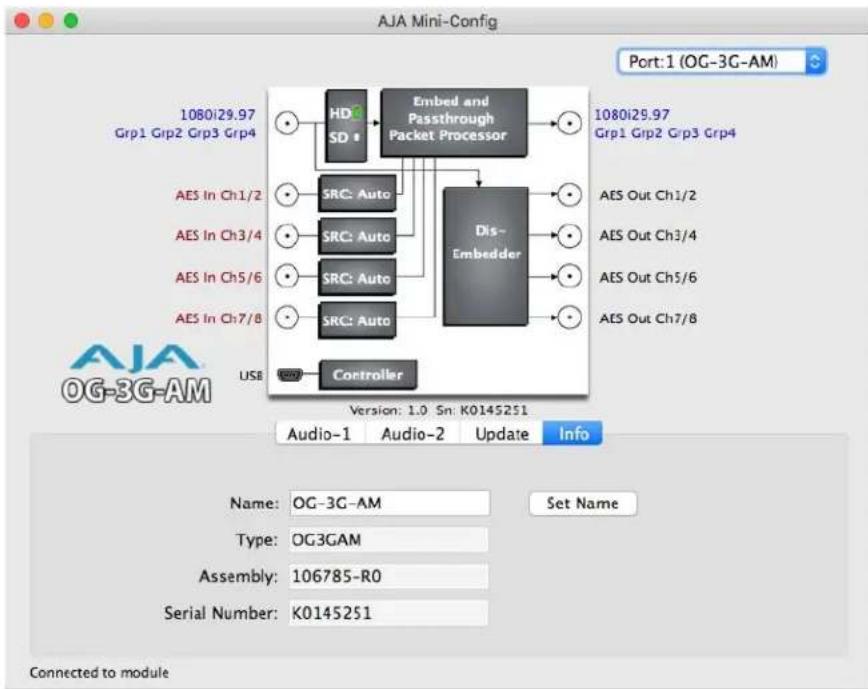
Info Screen
flowchart
graph TD
    A["1080i29.97 Grp1 Grp2 Grp3 Grp4"] --> B["HDG SD"]
    B --> C["Embed and Passthrough Packet Processor"]
    C --> D["Dis-Embedder"]
    E["AES In Ch1/2"] --> F["SRC: Auto"]
    G["AES In Ch3/4"] --> H["SRC: Auto"]
    I["AES In Ch5/6"] --> J["SRC: Auto"]
    K["AES In Ch7/8"] --> L["SRC: Auto"]
    M["USB"] --> N["Controller"]
    O["1080i29.97 Grp1 Grp2 Grp3 Grp4"] --> P["AES Out Ch1/2"]
    Q["AES Out Ch3/4"] --> R["AES Out Ch3/4"]
    S["AES Out Ch5/6"] --> T["AES Out Ch5/6"]
    U["AES Out Ch7/8"] --> V["AES Out Ch7/8"]
This screen provides basic information about the Mini-Converter. This information is mostly useful when calling AJA Support for service or technical support.
Name This field allows you to give your Mini-Converter a name. This may be useful if you have several Mini-Converters attached to a Mac/PC via USB so you can distinguish one of them easily (especially if they're the same model).
Type: This is the factory set model name of the Mini-Converter (OG-3G-AM).
Assembly: This is the factory assembly number.
Serial Number: This is the factory set unique serial number of your OG-3G-AM. If you ever call AJA Support for service, you may be asked for this number.
Appendix A: Specifications
Video Formats
1 x 3 Gb SDI (level A or • (2K) 2048 x 1080p 23.98, 24, 25, 29.97, 30, 50, 59.94, 60
B) • (2K) 2048 x 1080PsF 23.98, 24, 25, 29.97, 30
• (HD) 1920 x 1080p 23.98, 24, 25, 29.97, 30, 50, 59.94, 60
• (HD) 1920 x 1080PsF 23.98, 24, 25, 29.97, 30
• (HD) 1920 x 1080i 25, 29.97, 30
• (HD) 1280 x 720p 50, 59.94, 60
1 x 1.5 Gb SDI · (2K) 2048 x 1080p 23.98, 24, 25, 29.97, 30
• (2K) 2048 x 1080PsF 23.98, 24, 25, 29.97, 30
• (HD) 1920 x 1080p 23.98, 24, 25, 29.97, 30
• (HD) 1920 x 1080PsF 23.98, 24, 25, 29.97, 30
• (HD) 1920 x 1080i 25, 29.97, 30
• (HD) 1280 x 720p 23.98, 24, 25, 29.97, 30, 50, 59.94, 60
1 x 270 Mb SDI · (SD) 525i
• (SD) 625i
Video Input Digital · 1 x 3G-SDI BNC, SMPTE-259/292/424
Video Output • 1 x 3G-SDI BNC, SMPTE-259/292/424 Digital
Audio Input Digital · 4 x BNC
Audio Data Formats · AES3 2003
• S M P T E S T 3 3 7
Digital Audio Converters • 24-bit
Embedded Audio • SDI embedded audio, 24-bit, 16-Channel*
- SMPTE ST 272 (SD): 20-bit, 48 KHz synchronous
• SMPTE ST 299 (3G/HD): 24-bit, 48 KHz synchronous
- Incoming embedded audio can be passed, removed, or overridden
*NOTE: 2048 x 1080p/PsF 29.97 and 30 formats support a maximum of 8-Channels embedded audio
Audio Output Digital
• SDI embedded audio, 24-bit, 8-channel
• 4 x B N C
Embed Path Audio Latency
(Time measured between audio input and video output connector):
• 1500 usec (SRC ON)
• 400 usec (SRCOFF)
Disembed Path Audio Latency
(Time measured between video input and audio output connector):
• 210 usec
User Interface · AJA Mini-Config software (via USB on front panel)
Slots · Two slots required for each card
Size · openGear standard form-factor, front slot and rear card
• Rear Card: OG-10-BNC-Rear
• 10 x BNC, SMPTE-259/292/424
Weight·0.5 lb
Power · openGear frame compatible, 5.0 watts max per card
Environment · Operating Temperature: 0C to 40C (32F to 104F)
- Storage Temperature: -40C to 60C (-40F to 140F)
- Operating Relative Humidity: 10-90% non-condensing
- Operating Altitude: <3,000m (<10,000ft)
Appendix B: Safety and Compliance
Federal Communications Commission (FCC) Compliance Notices
Class A Interference Statement
This equipment has been tested and found to comply with the limits for a Class A digital device, pursuant to Part 15, Subpart B of the FCC Rules. These limits are designed to provide reasonable protection against harmful interference in a residential installation.
This equipment generates, uses, and can radiate radio frequency energy and, if not installed and used in accordance with the instructions, may cause harmful interference to radio communications. However, there is no guarantee that interference will not occur in a particular installation. If this equipment does cause harmful interference to radio or television reception, which can be determined by turning the equipment off and on, the user is encouraged to try to correct the interference by one or more of the following measures:
- Reorient or relocate the receiving antenna.
- Increase the separation between the equipment and receiver.
- Connect the equipment into an outlet on a circuit different from that to which the receiver is connected.
- Consult the dealer or an experienced radio/TV technician for help.
FCC Caution
This device complies with Part 15 of the FCC Rules. Operation is subject to the following two conditions: (1) This device may not cause harmful interference, and (2) this device must accept any interference received, including interference that may cause undesired operation.
Canadian ICES Statement
Canadian Department of Communications Radio Interference Regulations
This digital apparatus does not exceed the Class A limits for radio-noise emissions from a digital apparatus as set out in the Radio Interference Regulations of the Canadian Department of Communications. This Class A digital apparatus complies with Canadian ICES-003.
European Union and European Free Trade Association (EFTA) Regulatory Compliance
This equipment may be operated in the countries that comprise the member countries of the European Union and the European Free Trade Association. These countries, listed in the following paragraph, are referred to as The European Community throughout this document:
AUSTRIA, BELGIUM, BULGARIA, CYPRUS, CZECH REPUBLIC, DENMARK, ESTONIA, FINLAND, FRANCE, GERMANY, GREECE, HUNGARY, IRELAND, ITALY, LATVIA, LITHUANIA, LUXEMBOURG, MALTA, NETHERLANDS, POLAND, PORTUGAL, ROMANIA, SLOVAKIA, SLOVENIA, SPAIN, SWEDEN, UNITED KINGDOM, ICELAND, LICHTENSTEIN, NORWAY, SWITZERLAND
Declaration of Conformity
Marking by this symbol indicates compliance with the Essential Requirements of the EMC Directive of the European Union 2004/108/EC.

This equipment meets the following conformance standards:
Safety: EN 60065: 2002 + A1: 2006 + A11: 2008 + A2: 2010 + A12: 2011 (Bauart License)
IEC 60065: 2001 + A1: 2005 + A2: 2010 (CB Scheme Report/Certificate)
Additional licenses issued for specific countries available on request.
Emissions: EN 55032: 2012, CISPR 22: 2008, EN 55022: 2010, EN 61000-3-2: 2009, EN 61000-3-3:2008
Immunity: EN 55103-2: 2009, EN 61000-4-2:2009, EN 61000-4-3:2010, EN 61000-4-4:2010, EN 61000-4-5:2005, EN 61000-4-6:2009, EN 61000-4-11:2004
Environments: E2, E3 and E4
The product is also licensed for additional country specific standards as required for the International Marketplace.

Warning!
This is a Class A product. In a domestic environment, this product may cause radio interference, in which case, the user may be required to take appropriate measures.
This symbol on the product or its packaging indicates that this product must not be disposed of with your other household waste. Instead, it is your responsibility to dispose of your waste equipment by handing it over to a designated collection point for the recycling of waste electrical and electronic equipment. The separate collection and recycling of your waste equipment at the time of disposal will help conserve natural resources and ensure that it is recycled in a manner that protects human health and the environment. For more information about where you can drop off your waste for recycling, please contact your local authority, or where you purchased your product.
Korean KCC Compliance Statement
A급 기기 (업무용 방송통신기자재)
Class A (Broadcasting Communication Equipment for Office Use)
As an electromagnetic wave equipment for office use (Class A), this equipment is intended to use in other than home area. Sellers or users need to take note of this.
Taiwan Compliance Statement
警告使用者:
This is a Class A product based on the standard of the Bureau of Standards, Metrology and Inspection (BSMI) CNS 13438, Class A. In a domestic environment this product may cause radio interference in which case the user may be required to take adequate measures.
Japanese Compliance Statement
1. Class A | TE
This is a Class A product based on the standard of the VCCI Council (VCCI V-3/2015.04). If this equipment is used in a domestic environment, radio interference may occur, in which case, the user may be required to take corrective actions.
Translated Warning and Caution Messages
The following caution statements, warning conventions, and warning messages apply to this product and manual

Warning Symbol

Hazard Symbol

Caution Symbol
Before Operation Please Read These Instructions

Warning!
Read and follow all warning notices and instructions marked on the product or included in the documentation.
Do not use this device near water and clean only with a dry cloth.
Do not block any ventilation openings. Install in accordance with the manufacturer's instructions.
Do not install near any heat sources such as radiators, heat registers, stoves, or other apparatus (including amplifiers) that produce heat.
Refer all servicing to qualified service personnel. Servicing is required when the device has been damaged in any way, such as power-supply cord or plug is damaged, liquid has been spilled or objects have fallen into the device, the device has been exposed to rain or moisture, does not operate normally, or has been dropped.
Disconnect the external AC power supply line cord(s) from the mains power before moving the unit.
High Voltage. This situation or condition can cause injury due to electric shock.
Only use attachments and accessories specified and/or sold by the manufacturer.
Do not defeat the safety purpose of the polarized or grounding-type plug. A polarized plug has two blades with one wider than the other. A grounding type plug has two blades and a third grounding prong. The wide blade or the third prong are provided for your safety. If the provided plug does not fit into your outlet, consult an electrician for replacement of the obsolete outlet.
Since the Mains plug is used as the disconnection for the device, it must remain readily accessible and operable.
Protect the power cord from being walked on or pinched particularly at plugs, convenience receptacles, and the point where they exit from the device.
Unplug this device during lightning storms or when unused for long periods of time.
Ensure Mains Power is disconnected before installing the OG-3-FR modules into the frame, or installing and removing options. If a Mains switch is not provided, the power cord(s) of this equipment provide the means of disconnection. The socket outlet must be installed near the equipment and must be easily accessible.
Dual Power Cord Notice-please read this. To reduce the risk of electrical shock, disconnect both power cords before servicing equipment.
The OG-3-FR front fan door is heavy. Remove with Caution.
AJA Video Systems, Inc. (AJA Video) warrants that this product will be free from defects in materials and workmanship for a period of five years from the date of purchase. If a product proves to be defective during this warranty period, AJA Video, at its option, will either repair the defective product without charge for parts and labor, or will provide a replacement in exchange for the defective product.
In order to obtain service under this warranty, you the Customer, must notify AJA Video of the defect before the expiration of the warranty period and make suitable arrangements for the performance of service. The Customer shall be responsible for packaging and shipping the defective product to a designated service center nominated by AJA Video, with shipping charges prepaid. AJA Video shall pay for the return of the product to the Customer if the shipment is to a location within the country in which the AJA Video service center is located. Customer shall be responsible for paying all shipping charges, insurance, duties, taxes, and any other charges for products returned to any other locations.
This warranty shall not apply to any defect, failure or damage caused by improper use or improper or inadequate maintenance and care. AJA Video shall not be obligated to furnish service under this warranty a) to repair damage resulting from attempts by personnel other than AJA Video representatives to install, repair or service the product, b) to repair damage resulting from improper use or connection to incompatible equipment, c) to repair any damage or malfunction caused by the use of non-AJA Video parts or supplies, or d) to service a product that has been modified or integrated with other products when the effect of such a modification or integration increases the time or difficulty of servicing the product.
THIS WARRANTY IS GIVEN BY AJA VIDEO IN LIEU OF ANY OTHER WARRANTIES, EXPRESS OR IMPLIED. AJA VIDEO AND ITS VENDORS DISCLAIM ANY IMPLIED WARRANTIES OF MERCHANTABILITY OR FITNESS FOR A PARTICULAR PURPOSE. AJA VIDEO'S RESPONSIBILITY TO REPAIR OR REPLACE DEFECTIVE PRODUCTS IS THE WHOLE AND EXCLUSIVE REMEDY PROVIDED TO THE CUSTOMER FOR ANY INDIRECT, SPECIAL, INCIDENTAL OR CONSEQUENTIAL DAMAGES IRRESPECTIVE OF WHETHER AJA VIDEO OR THE VENDOR HAS ADVANCE NOTICE OF THE POSSIBILITY OF SUCH DAMAGES.
C
Card Overview 5
Compliance Statements 25
D
Dashboard Control System 6
Documentation
Downloading 14
Mini-Converter 13
I
Info Screen 22
M
Mini-Config
Acquiring 13
Installation on Mac 15
Installation on PC 14
Operation 16
Running Multiple Converters 17
Screen Description 17
Startup 15
Mini-Converter Documentation 13
0
Overview
Card 5
S
Safety Statements 25
Software Update Procedure 21
Specifications 23
U
Update Tab Screen 21
W
Warnings
Safety 25

- Installation & Operation Guide
- Table of Contents
- Notices....4
- Chapter 1: OG-3G-AM ....5
- Chapter 2: Operation....10
- Appendix A: Specifications .....23
- Appendix B: Safety and Compliance....25
- Warranty Information....36
- Trademarks
- Copyright
- Contacting Support
- Chapter 1: OG-3G-AM
- Card Overview
- Features
- OG-3G-AM Simplified Block Diagram
- Connectors for OG-3G-AM
- Indicators
- User Controls
- DIP Switches
- openGear and AJA
- Parts Lists
- Installation
- Summary
- Unpacking
- Rear BNC Card Installation
- Front Card Installation
- Cabling
- Chapter 2: Operation
- Default Operational Settings
- DIP Switch Settings
- Switch 6 Embedded Channel Mapping
- Switch 7 Disembedding Channel Mapping
- USB Control and Setup—Using AJA Mini-Config
- Connecting the USB Cable to the USB Port on the OG-3G-AM Card
- Acquiring Mini-Config
- Mini-Converter Documentation
- Installing Mini-Config
- Running Mini- Config
- PC Startup
- Mac Startup
- Saving Setups
- Operating Mini- Config
- Running Multiple Mini-Converters
- Tabbed Screens
- Audio-1 Screen
- AES Audio Inputs
- AES Audio Outputs
- Audio-2 Screen
- Packet Processing Control
- About SRC Settings
- Update Screen
- Software Update Procedure
- Info Screen
- Appendix A: Specifications
- Video Formats
- Audio Output Digital
- Embed Path Audio Latency
- Disembed Path Audio Latency
- Appendix B: Safety and Compliance
- Federal Communications Commission (FCC) Compliance Notices
- Class A Interference Statement
- FCC Caution
- Canadian ICES Statement
- European Union and European Free Trade Association (EFTA) Regulatory Compliance
- Declaration of Conformity
- Warning!
- Korean KCC Compliance Statement
- Taiwan Compliance Statement
- 警告使用者:
- Japanese Compliance Statement
- Class A | TE
- Translated Warning and Caution Messages
- Before Operation Please Read These Instructions
- C
- D
- I
- M
- 0
- S
- U
- W
Brand : AJA
Model : OG-3G-AM
Category : Audio/video converter