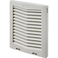
HG1000404 - Fan Hoffman - Free user manual and instructions
Find the device manual for free HG1000404 Hoffman in PDF.


| Product Type | Uncategorized Device |
| Brand | Hoffman |
| Model | HG1000404 |
| Dimensions (W x H x D) | 30 cm x 20 cm x 15 cm |
| Weight | 1.5 kg |
| Power Supply | AC 220-240V, 50/60Hz |
| Power Consumption | 100 W |
| Main Functions | On/Off, adjustable settings, indicator light |
| Materials | Plastic body, metal components |
| Color | White/Black (typical) |
| Operating Temperature | 0°C to 40°C |
| Storage Temperature | -20°C to 60°C |
| Cleaning Instructions | Wipe with a damp cloth; do not immerse in water |
| Safety Precautions | Disconnect from power before cleaning; keep away from children |
| Spare Parts Availability | Contact Hoffman customer service |
| Repair Information | Refer to manual or authorized service center |
| Certifications | CE, RoHS |
| Package Contents | Device, power cord, user manual |
Frequently Asked Questions - HG1000404 Hoffman
User questions about HG1000404 Hoffman
0 question about this device. Answer the ones you know or ask your own.
Ask a new question about this device
Download the instructions for your Fan in PDF format for free! Find your manual HG1000404 - Hoffman and take your electronic device back in hand. On this page are published all the documents necessary for the use of your device. HG1000404 by Hoffman.
USER MANUAL HG1000404 Hoffman
natural_image
Collection of black and white air vent grilles with ventilation slots, no visible text or symbolsSide-Mount Filter Fans and Grilles
HF/HG Models
INSTRUCTION MANUAL
TABLE OF CONTENTS
Installation Instructions....3
Wire Diagrams....5
How to Read Model Numbers......6
Filter Cleaning / Replacement....6
Replacement Parts 7
Warranty 7

CAUTION
Before cutting holes in the sides of the enclosure, verify all internal components are clear of the cutting tool to avoid damaging installed components.
INSTALLATION INSTRUCTIONS
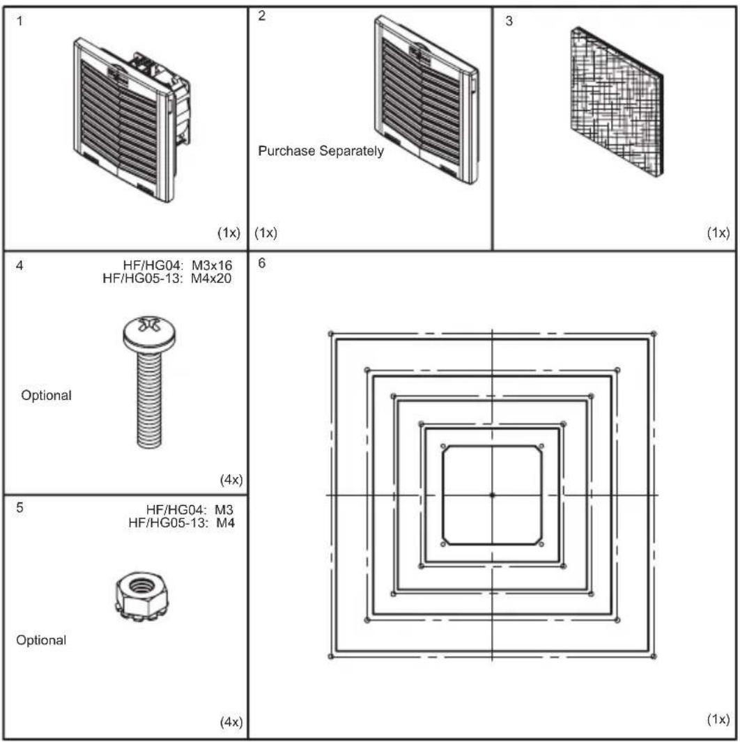
- Apply cutout template to the side of the enclosure located as desired. See Figure 1
- Cutout hole in enclosure using the appropriate cutout size for the model you purchased.
- Deburr the cutting edge.
- Insert fan or grille and push into opening until all four corners are snapped and locked. See Figure 2.
- Mounting fasteners are not required for panel or enclosure material thickness less than .10 (2.5 mm). For panel or enclosure material thickness between .10 (2.5 mm) and .14 (3.5 mm), mounting fasteners are recommended. For panel or enclosure material thickness greater than .14 (3.5 mm), mounting fasteners are required in order to maintain the IP / Type 12 rating.
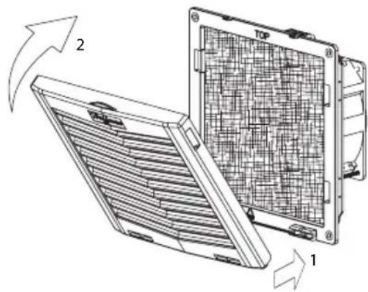
- In order to install the mounting fasteners, removal of the grille is required. Remove the grille by pulling from the top of the grille to 45^ maximum as shown in Figure 3 on page 4. Then pull from the bottom as shown in Figure 4 on page 4. NOTE: The orientation "Top" directs the louvers downward. This is for reference only; the assembly can be installed to orient louvers in any direction.
- It may be necessary to drill out the mounting holes in the filter housing. For model HF04, use a 1/8 (3 mm) drill bit. For models HF05, HF09, HF10 and HF13, use a 5/32 (4 mm) drill bit.
- Torque fasteners to 20-25 in-lbs (2.3-2.8 Nm). See Figure 5 on page 4.
- Install the grille as shown in Figure 2
- Verify the location of the enclosure with installed filter fan has a minimum clearance of 7.00 (178 mm). See Figure 7 on page 4
- Wire the filter fan following the Wire Diagrams on page 5 for the appropriate model being installed.

natural_image
Technical line drawing of a rectangular enclosure with a circular pattern on the side panel, labeled with number 6 (no text or symbols beyond label)Figure 1

Figure 2
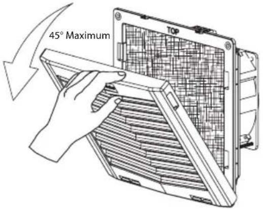
Figure 3
![20-25 in-lbs [2.3-2.8 Nm] ⑤ ④](/content/2026/05/1074431/images/360a113f2d6e9feb044c43128a249fc229c6035548417fea9be02092d4aff667.jpg)
Figure 5

natural_image
Technical line drawing of a device with a lid and fan blade, showing internal structure and a directional arrow (no text or symbols)Figure 4
natural_image
Diagram of a solar panel with labeled components and directional arrows indicating rotation (no text or symbols present)Figure 6
![7.0in MIN [178mm MIN]](/content/2026/05/1074431/images/794b2378e4a1939a4603fbc68086220d75ecb2ce4dfd066fbbb6d4a748c814f9.jpg)
Figure 7
WIRE DIAGRAMS

WIRING DIAGRAM HF04, HF05, HF09, HF10 AC POWERED
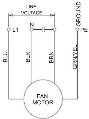
WIRING DIAGRAM HF13 AC POWERED
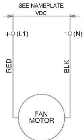
WIRING DIAGRAM HF04, HF05, HF09, HF10 DC POWERED

WIRING DIAGRAM HF13 - FULL SPEED DC POWERED

WIRING DIAGRAM HF13 - VARIABLE SPEED DC POWERED
HOW TO READ MODEL NUMBERS
| HF 04 16 | 4 0 4 | ||||
| 1 2 3 4 5 | 6 |
- Filter fan / Grille
- Size
- Voltage: 16 = AC 115/50/60/1
$$ 2 6 = \mathrm{AC} 2 3 0 / 5 0 / 6 0 / 1 $$
$$ 2 4 = \mathrm{DC} 2 4 \mathrm{V} $$
$$ 4 8 = \mathrm{DC} 4 8 \mathrm{V} $$
- IP Rating: 4 = IP54
$$ 5 = \mathrm{IP} 5 5 $$
- Version
- Color: 3 = RAL9011 Black
$$ 4 = \text { RAL } = \text { RAL7035 Light Gray } $$
FILTER CLEANING / REPLACEMENT
| Replacement Filter Part Numbers | ||
| Fan/Grille Models | IP54 / Type 12(≈ .50 [14 mm] thick) | IP55 / Type 12(≈ .75 [20 mm] thick) |
| HF/HG04 8913442 | 3R -- | |
| HF/HG05 8913442 | 4R 89136408R | |
| HF/HG09 8913442 | 5R 89136409R | |
| HF/HG10 8913442 | 6R 89136410R | |
| HF/HG13 8913442 | 7R* 89136411R | |
*Note: HF/HG13 replacement filters are not approved for IP54; only Type 12.
- Open louvered grille.
- Wash filter in warm water. Use mild detergent if necessary.
- For greasy matter, wash in warm water containing a grease solvent.
- Do not wring the filter.


REPLACEMENT PARTS
| Model | RAL7035 Light Gray RAL9011 Black | |||
| Grille Housing | Grille Housing | |||
| HF04 89123 | 894SP 89133137 | SP 89131499SP | 89133137SP | |
| HF05 89122 | 973SP 89133138 | SP 89131495SP | 89133138SP | |
| HF09 89122 | 907SP 89133139 | SP 89131484SP | 89133139SP | |
| HF10 89123 | 456SP 89133140 | SP 89131496SP | 89133140SP | |
| HF13 89124 | 454SP HG13004 | 04 89131502SP | HG1300403 | |
| HG04 89123 | 894SP HG04004 | 04 89131499SP | HG0400403 | |
| HG05 89122 | 973SP HG05004 | 04 89131495SP | HG0500403 | |
| HG09 89122 | 907SP HG09004 | 04 89131484SP | HG0900403 | |
| HG10 89123 | 456SP HG10004 | 04 89131496SP | HG1000403 | |
| HG13 89124 | 454SP HG13004 | 04 89131502SP | HG1300403 | |
WARRANTY
Please register your product and reference the Hoffman Cooling Product Warranty located here: https://hoffman.nvent.com/en/hoffman/warranty-information
nVent
nVent
2100 Hoffman Way
Anoka, MN 55303 USA
+1.763.422.2211
+1.763.576.3200
nVent.com
Brand : Hoffman
Model : HG1000404
Category : Fan