
PAC527FW - Wall socket Chief - Free user manual and instructions
Find the device manual for free PAC527FW Chief in PDF.


| Product Type | Wall Socket |
| Model | PAC527FW |
| Brand | Chief |
| Voltage Rating | 125 V AC |
| Current Rating | 15 A |
| Outlet Configuration | NEMA 5-15R |
| Number of Outlets | 1 |
| Color | White |
| Material | Thermoplastic |
| Dimensions (W x H x D) | 4.5 x 2.75 x 1.5 inches |
| Weight | 0.5 lbs |
| Safety Certifications | UL Listed, Tamper Resistant |
| Operating Temperature | -40°F to 140°F |
| Flame Retardant | Yes, UL 94 V-0 rated |
| Installation | Flush mount, standard single gang box |
| Wiring | Side or back wiring, 14-10 AWG |
| Grounding | Self-grounding clip |
| Includes | Outlet, mounting screws, wall plate |
Frequently Asked Questions - PAC527FW Chief
User questions about PAC527FW Chief
0 question about this device. Answer the ones you know or ask your own.
Ask a new question about this device
Download the instructions for your Wall socket in PDF format for free! Find your manual PAC527FW - Chief and take your electronic device back in hand. On this page are published all the documents necessary for the use of your device. PAC527FW by Chief.
USER MANUAL PAC527FW Chief
INSTALLATION INSTRUCTIONS
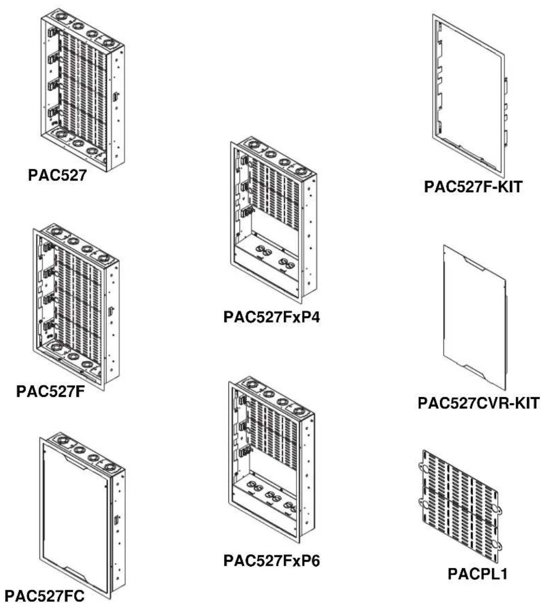
In-Wall Box and Accessories
DISCLAIMER
Milestone AV Technologies and its affiliated corporations and subsidiaries (collectively "Milestone"), intend to make this manual accurate and complete. However, Milestone makes no claim that the information contained herein covers all details, conditions or variations, nor does it provide for every possible contingency in connection with the installation or use of this product. The information contained in this document is subject to change without notice or obligation of any kind. Milestone makes no representation of warranty, expressed or implied, regarding the information contained herein. Milestone assumes no responsibility for accuracy, completeness or sufficiency of the information contained in this document.
Chief® is a registered trademark of Milestone AV Technologies. All rights reserved.
DEFINITIONS
MOUNTING SYSTEM: A MOUNTING SYSTEM is the primary Chief product to which an accessory and/or component is attached.
ACCESSORY: AN ACCESSORY is the secondary Chief product which is attached to a primary Chief product, and may have a component attached or setting on it.
COMPONENT: A COMPONENT is an audiovisual item designed to be attached or resting on an accessory or mounting system such as a video camera, CPU, screen, display, projector, etc.

WARNING: A WARNING alerts you to the possibility of serious injury or death if you do not follow the instructions.

CAUTION: A CAUTION alerts you to the possibility of damage or destruction of equipment if you do not follow the corresponding instructions.

IMPORTANT SAFETY INSTRUCTIONS

WARNING: Failure to read, thoroughly understand, and follow all instructions can result in serious personal injury, damage to equipment, or voiding of factory warranty! It is the installer's responsibility to make sure all accessories are properly assembled and installed using the instructions provided.

WARNING: Failure to provide adequate structural strength for this accessory can result in serious personal injury or damage to equipment! It is the installer's responsibility to make sure the structure to which this accessory is attached can support five times the combined weight of all equipment. Reinforce the structure as required before installing the accessory.

WARNING: Exceeding the weight capacity can result in serious personal injury or damage to equipment! It is the installer's responsibility to make sure the combined weight of all components located in the accessory does not exceed 40 lbs (18.1 kg).
• Each PAC527 may hold up to 4 individual backplanes (2 complete) and each individual backplane may hold a maximum weight of 10 lbs (4.5 kg)
- A half backplane (after separation) may hold a maximum weight of 5 lbs (2.3 kg).

WARNING: Use this accessory only for its intended use as described in these instructions. Do not use attachments not recommended by the manufacturer.

WARNING: Never operate this accessory if it is damaged. Return the accessory to a service center for examination and repair.

WARNING: For indoor use only.
IMPORTANT ! : The PAC527 accessory is designed to be mounted to either a 2" x 3" or 2" x 4" wood stud wall 16" on center, or a 2" x 3"-25ga (minimum) or 2" x 4"-25ga (minimum) steel studs wall.
NOTE: Spacings - Minimum spacings between the 120 Vac power components and the A/V components shall be maintained for safe operation of the equipment when installed in accordance with the National Electric Code, ANSI/NFPA 70.
NOTE: When selecting a Listed 120 Vac Receptacle for use as the main power source for the PAC series boxes (to power the A/V equipment), make sure that AC Receptacle is rated at least 15A and it is used in the building's AC branch circuit that is connected to a circuit breaker rated at least 15A. Do not connect more than 12A from the Receptacle.
In the U.S., the equipment shall be installed per the applicable requirements of the National Electrical Code, CSA C22.1.
In Canada, the equipment shall be installed per the applicable requirements of the National Electrical Code, ANS/NFPA 70.
NOTE: It is the installer's responsibility to ensure that the enclosure is bonded to the ground in the switch box, in accordance with the National Electric Code, ANSI/NFPA 70 or Canadian Electrical Code, CSA C22.1. A green grounding screw is provided in the enclosure for the purpose, if required.
IMPORTANT ! : The PAC527 mounts are designed to accommodate the following Chief power kits ONLY:
- PAC527P4-KIT
- PAC527P6-KIT
--SAVE THESE INSTRUCTIONS--
DIMENSION DRAWINGS are located at the end of these Installation Instructions.
ADDITIONAL SAFETY INSTRUCTIONS SPECIFIC TO PAC527FxP4 / PAC527FxP6
READ ALL INSTRUCTIONS BEFORE USING THIS PRODUCT!!!!

DANGER: TO REDUCE THE RISK OF
ELECTRIC SHOCK:
- Always turn off power at source before installing the outlet.

WARNING: TO REDUCE THE RISK OF
BURNS, FIRE, ELECTRIC SHOCK, OR INJURY TO PERSONS:
• Always turn off power at source before servicing or removing the outlet.
- Do not use outdoors - For indoor use only.
- Route cables as shown in these installation instructions.
• To disconnect, turn off power at source.

WARNING: RISK OF ELECTRIC SHOCK!
Make sure the outlet is properly grounded. See grounding instructions.

CAUTION: This equipment must be installed
and assembled by qualified service personnel in accordance with local building and electrical codes.
NOTE: Knockouts are provided for ease of installation. Any unused knockouts that have been punched are to be closed up with a metal plug.
Ambient Temperature - The manufacturer's maximum ambient temperature is 104°F (40°C) and minimum ambient temperature is 30°F (-1°C) so that the installer is able to determine acceptability of use of Accessories and components.
--SAVE THESE INSTRUCTIONS--
IMPORTANT ! : DIMENSION DRAWINGS are located at the end of these Installation Instructions.
TABLE OF CONTENTS
| DISCLAIMER | 2 |
| DEFINITIONS | 2 |
| IMPORTANT SAFETY INSTRUCTIONS | 2 |
| ADDITIONAL SAFETY INSTRUCTIONS(PAC527FxP4 / PAC527FxP6) | 3 |
| TABLE OF CONTENTS | 3 |
| LEGEND | 4 |
| TOOLS REQUIRED FOR INSTALLATION | 5 |
| PARTS INCLUDED | 5 |
| OPTIONAL PARTS (for custom configuration). | 7 |
| ADDITIONAL INFORMATION | 7 |
| ASSEMBLY AND INSTALLATION | 7 |
| Locating PAC527 | 7 |
| Instructions for PAC527FxP4/PAC527FxP6Only | 8 |
| Isolated Ground Receptacle | 8 |
| References | 8 |
| Prepare for Wiring | 8 |
| Outlet Box Use | 9 |
PAC527 Site Preparation.... 10
PAC527 Box Preparation and Installation.....10
Installing Backplanes (PACPL1)....12
Adding Template/Temporary Cover.....12
PAC527F-KIT....13
PAC527CVR-KIT....13
Dimensions - PAC527....14
Dimensions - PAC527F....15
Dimensions - PAC527FC....16
Dimensions - PAC527FxP4....17
Dimensions - PAC527FxP6.... 17
Dimensions - PAC527FxPx....17
Dimensions - PAC527F-KIT....18
Dimensions - PAC527CVR-KIT.... 18
Dimensions - PACPL1.... 19
LEGEND
 | Tighten Fastener |  | Pencil Mark |
| Apretar elemento de fijación | Marcar con lápiz | ||
| Befestigungsteil festziehen | Stiftmarkierung | ||
| Apertar fixador | Marcar com lápis | ||
| Serrare il fissaggio | Segno a matita | ||
| Bevestiging vastdraaien | Potloodmerkteken | ||
| Serrez les fixations | Marquage au crayon | ||
 | Loosen Fastener |  | Drill Hole |
| Aflojar elemento de fijación | Perforar | ||
| Befestigungsteil lösen | Bohrloch | ||
| Desapertar fixador | Fazer furo | ||
| Allentare il fissaggio | Praticare un foro | ||
| Bevestiging losdraaien | Gat boren | ||
| Desserrez les fixations | Percez un trou | ||
 | Phillips Screwdriver |  | Adjust |
| Destornillador Phillips | Ajustar | ||
| Kreuzschlitzschraubendreher | Einstellen | ||
| Chave de fendas Phillips | Ajustar | ||
| Cacciavite a stella | Regolare | ||
| Kruiskopschroevendraaier | Afstellen | ||
| Tournevis à pointe cruciforme | Ajuster | ||
 | Open-Ended Wrench |  | Remove |
| Llave de boca | Quitar | ||
| Gabelschlüssel | Entfernen | ||
| Chave de bocas | Remover | ||
| Chiave a punte aperte | Rimuovere | ||
| Steeksleutel | Verwijderen | ||
| Clé à fourche | Retirez | ||
 | By Hand |  | Optional |
| A mano | Opcional | ||
| Von Hand | Optional | ||
| Com a mão | Opcional | ||
| A mano | Opzionale | ||
| Met de hand | Optie | ||
| À la main | En option | ||
 | Hex-Head Wrench |  | Security Wrench |
| Llave de cabeza hexagonal | Llave de seguridad | ||
| Sechskantschlüssel | Sicherheitsschlüssel | ||
| Chave de cabeça sextavada | Chave de segurança | ||
| Chiave esagonale | Chiave di sicurezza | ||
| Zeskantsleutel | Veiligheidssleutel | ||
| Clé à tête hexagonale | Clé de sécurité |
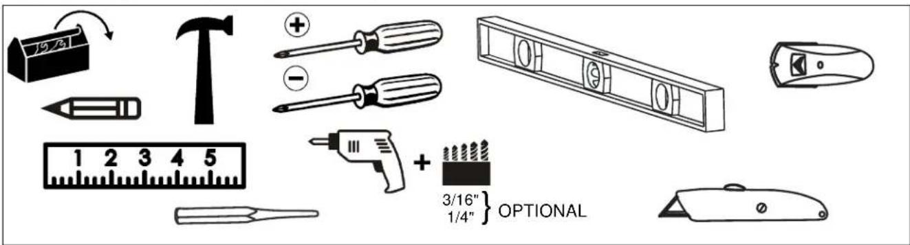
TOOLS REQUIRED FOR INSTALLATION
PARTS INCLUDED
![PAC527 E (1) [PAC527] F (1) [Template/ Temporary Cover] A (4) 1/4 x 2-1/2" B (8) 06-32" C (8) 06 x 3/8" D (4) 3/8" PAC527F G (1) [PAC527F] F (1) [Template/ Temporary Cover] A (4) 1/4 x 2-1/2" B (8) 06-32" C (8) 06 x 3/8" D (4) 3/8" PAC527FC H (1) [PAC527FC] F (1) [Template/ Temporary Cover] A (4) 1/4 x 2-1/2" B (8) 06-32" C (8) 06 x 3/8" D (4) 3/8"](/content/2026/05/1074158/images/9e2733f23bf1980ebe3161a900bcdaa2e668cee72240982e945c7eca88ca2fb8.jpg)
PARTS - continued

OPTIONAL PARTS PER CUSTOM CONFIGURATION (NOT INCLUDED)

natural_image
Technical line drawings of three mechanical components: a cylindrical housing, a flanged housing with a bolt, and a separate cylindrical component (no text or symbols present)Conduit connectors

Conduit pipe 1/2", 1" or 1-1/4"

natural_image
Line drawing of an electrical enclosure with mounting flanges and internal cavities (no text or symbols)3" x 2" Steel Old
Work Switch Box
(2" deep)
Raco #420 or
equivalent

Electrical
outlet

Narrow Handy Box
Cover, Duplex
Raco #864 or
equivalent
ADDITIONAL INFORMATION
NOTE: Grounding screw installed at factory in PAC527, PAC527F, PAC527FC, PAC527FxP4, and PAC527FxP6 in-wall boxes. Grounding screw is located on one side of the PAC527 box.
10-32
grounding screw


Earthing symbol IEC 60418 No. 5019
affixed adjacent to grounding terminal
ASSEMBLY AND INSTALLATION
IMPORTANT ! : In the following instructions, the reference to PAC527 includes the following models:
- PAC527
- PAC527F
- PAC527FC
- PAC527FxP4
- PAC527FxP6
The PAC527 is intended for use in both installations where an existing finished drywall wall is present, and where the wall surface has not been finished and the structural studs are exposed. The wall then must be finished around the opening of the box after the box has been installed.


WARNING: All wiring should be performed by a licensed electrician following all local codes and ordinances.
Locating PAC527
- Identify a suitable wall location for the accessory.
- Locate and mark studs using a stud sensor.
- Identify possible structural conflicts (electrical wiring, plumbing, gas lines, HVAC).

WARNING: ELECTRICAL SHOCK HAZARD! CUTTING OR DRILLING INTO ELECTRICAL WIRES OR CABLES CAN CAUSE DEATH OR SERIOUS PERSONAL INJURY! ALWAYS make certain area behind mounting surfaces is free of electrical wires and cables before cutting, drilling or installing fasteners.

WARNING: EXPLOSION AND FIRE HAZARD! CUTTING OR DRILLING INTO GAS PLUMBING CAN CAUSE DEATH OR SERIOUS PERSONAL INJURY. ALWAYS make certain area behind mounting surfaces is free of gas, water, waste or any other plumbing before cutting, drilling or installing fasteners.
-
Determine all additional/optional components required:
-
Conduit pipe
- Conduit connectors (both large and small)
• Electrical box(es) (3" x 2")
• Steel electrical box cover(s)
• Electrical outlet(s)
INSTRUCTIONS FOR PAC527FxP4 / PAC527FxP6 Only
Isolated Ground Receptacle
This product incorporates an isolated ground receptacle, identified by the orange triangle on its face. This feature may be useful to reduce common noise in the connected equipment. Its intended use is to reduce electrical noise (electromagnetic interference) by purposely insulating the grounding circuit from any metallic wiring system. The ground pin of the receptacle is connected to the green/yellow wire and is isolated from the metal mounting yoke of the receptacle. The accessible metal of the product is connected to the green wire. If it is not desired to use this feature, connect the green/yellow and green wires together.
References
Application Guide for Isolated Ground Wiring Devices 2007, National Electrical Manufacturers Association (NEMA)
IEEE Std 1100™-2005, "IEEE Recommended Practice for Powering and Grounding Electronic Equipment" (Emerald Book), Section 8.5.3.2.
IEEE Std 142™-2007, "IEEE Recommended Practice for Grounding of Industrial and Commercial Power Systems" (Green Book), Sections 5.5.1, 5.5.2
NFPA-70, "National Electrical Code", Article 250.146 Connecting Receptacle Grounding Terminal to Box.
• (D) Isolated Ground Receptacles. Where installed for the reduction of electrical noise (electromagnetic interference) on the grounding circuit, a receptacle in which the grounding terminal is purposefully insulated from the receptacle mounting means shall be permitted. The receptacle grounding terminal shall be connected to an insulated equipment grounding conductor run with the circuit conductors. This equipment grounding conductor shall be permitted to pass through one or more panel boards without a connection to the panel board grounding terminal bar as permitted in 408.40, Exception, so as to terminate within the same building or structure directly at an equipment grounding conductor terminal of the applicable derived system or service. Where installed in accordance with the provisions of this section, this equipment grounding conductor shall also be permitted to pass through boxes, wire ways, or other enclosures without being connected to such enclosures.
- Informational Note: Use of an isolated equipment grounding conductor does not relieve the requirement for grounding the raceway system and outlet box.
C22.2 No. 1, "Canadian Electrical Code, Part 1", Rule 10-906 Bonding conductor connection to circuits and equipment.
• (6) A bonding jumper shall be installed to connect the bonding conductor to the grounding terminal of a receptacle and in such a manner that disconnection or removal of the receptacle will not interfere with, or interrupt grounding continuity.
• (7) In the case of metallically enclosed systems where the grounding path is provided by the metal enclosure, a bonding jumper shall be installed to bond the grounding terminal of the receptacle to the enclosure.
• (8) Notwithstanding Sub-rules (6) and (7), the bonding jumper, in the case of receptacles having grounding terminals isolated from the mounting strap required for special equipment, shall be permitted to be extended directly back to the distribution panel.

WARNING: IMPROPER INSTALLATION CAN RESULT IN ATH OR SERIOUS PERSONAL INJURY! This enclosure could be installed by qualified personnel.
NOTE: The PAC527FxP4 and PAC527FxP6 must be connected to a 15 Amp branch circuit.
Prepare for Wiring
-
Remove and save three Phillips head screws holding power kit within box. (See Figure 1)
-
Remove the power kit from the in-wall box. (See Figure 1)

Figure 1
- Wire the outlet box(es) as required. Refer to Table 1 and Table 2 for input and output specifications. (See Figure 2)
Table 1: Input Specifications
| Input | |
| Input voltage, frequency | 125 V AC, 60 Hz |
| Input connection type | 4x14 AWG stranded, UL Style1015, CSA TEW |
| Input Wire colors | Black - LineWhite - NeutralGreen - Box GroundGreen/Yellow - Isolated Ground |
| Input wire length (ft.) | 1 (with a 3/4" stripped end) |
Table 2: Output Specifications
| Output | |
| Output | 15 A, 1875 W |
| Power consumption | <0.5 watt |
| Fuses | Thermal current interrupting circuits are in MOVs |
| Quantity/Type | Duplex NEMA 5-15R Isolated Ground Receptacle |
| Color/Markings | Grey with protection symbol (Orange triangle) |

CAUTION: Isolated ground-mounting means NOT grounded. Grounding wire connection required.
IMPORTANT ! : If a separate isolated green/yellow ground wire is installed in the building wiring, attach it separately to the green/yellow isolated ground wire on box. If there is no separate green/yellow isolated ground wire, connect green ground wire to both green/yellow isolated ground wire and green box ground wire on box.
NOTE: The grounding conductors serving this outlet are to be connected to earth ground at the service equipment or other acceptable building earth ground such as the building frame in the case of a high-rise steel-frame structure. Connections should be made with minimum AWG 14 copper wire intended for use on a 15 Amp circuit. The conductors used to connect the outlet to the line or bus and ground shall not be any longer than necessary and shall avoid unnecessary bends.
NOTE: An insulated grounding conductor that is identical in size and insulation material and thickness to the grounded and ungrounded circuit supply conductors, except that it is green with or without one or more yellow stripes, is to be installed as part of the circuit that supplies the outlet. Refer to Table 250-122 of the National Electrical Code regarding the appropriate size of the grounding conductor.
NOTE: Pressure terminal or pressure splicing connectors and soldering lugs used in the installation of the outlet shall be identified as being suitable for the material of the conductors. Conductors of dissimilar metals shall not be intermixed in a terminal or splicing connector where physical contact occurs between dissimilar conductors unless the device is identified for the purpose and conditions of use.

Figure 2
- Replace the power kit in the PAC527, fitting the two slots in the power kit lower tab around two fasteners in the PAC527. (See Figure 1) and (See Figure 2)
- Tighten three Phillips screws to secure power kit in the PAC527. (See Figure 2)
Outlet Box Use
NOTE: The "PROTECTED" light indicates that the surge protection circuitry is active and operational.
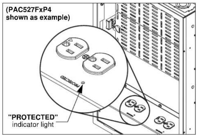
Figure 3
PAC527 Site Preparation
- Using a level, draw a horizontal line at the lower edge of the install site. (See Figure 4)
- Create an exploratory hole to confirm edge of the studs.
- Using the line drawn in Step 1 as lower edge and placing between studs, use the enclosed template (F) to draw lines around corners of template, and connect lines on bottom, top and sides. (See Figure 4)
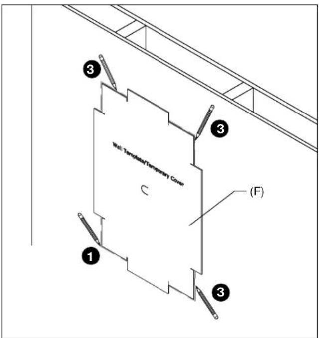
Figure 4
- Cut along outside edge of line using a utility knife and remove drywall.
- Check stud depth within the wall.
- If 3-1/2" or greater, proceed to PAC527 Box Preparation and Installation.
- If less than 3-1/2" deep, proceed to Step 6.
- If present, remove box flange by loosening screws. (See Figure 5)

CAUTION: Injury may occur on sharp edges. Carefully discard the removable tabs. Avoid sharp edges.
- Snap off removable tabs at perforations provided.
- Reinstall box flange.
- Fasten flange in place by tightening screws loosened in Step 6.

Figure 5
PAC527 Box Preparation and Installation
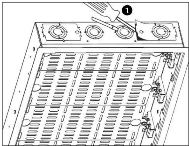
- Remove knock-outs as determined in Step 4 of Locating PAC527 section. (See Figure 6)
natural_image
Technical diagram of a device's internal structure with a tool and numbered component (no text or symbols)Figure 6
- Loosely attach required conduit and conduit connectors, switch boxes, outlets, etc (not included) to PAC527 to enable fitting into the wall opening. (See Figure 7)

Figure 7
- Feed conduit attached to PAC527 through cut-out in wall and insert PAC527 into wall opening. Tighten component connections.
- Drill pilot holes (at least 2 on each side of PAC527) into studs through mounting holes in PAC527.
• Wood studs: use 3/16" drill bit
• Steel studs: use 1/4" drill bit
- Install PAC527 to studs using four 1/4 x 2-1/2" Phillips flat head screws (A) and four 3/8" flat washers (D) through PAC527 and pilot holes. (See Figure 8)

Figure 8
NOTE: If installing in a stud wall BEFORE the drywall is installed, remove outer flange from PAC527 before installing the PAC527. (See Figure 9)

natural_image
Technical diagram of an open industrial rack cabinet with internal components and directional arrows indicating movement (no text or symbols present)Figure 9
Installing Backplanes (PACPL1)
IMPORTANT ! : The backplanes ship installed in the PAC527 / PAC527F / PAC527FC / PAC527FxP4 / PAC527FxP6 and may be removed, re-sized or rearranged as necessary. A backplane kit (PACPL1) is also available.
- FOR BACKPLANES SHIPPED IN PAC527 BOXES ONLY: Loosen screws (leaving them in the backplanes) holding the backplanes in the PAC527 box, and remove backplanes from box. (See Figure 10)
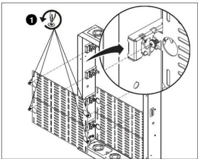
Figure 10
- If required, break the backplanes along the scored mid-line. (See Figure 11)

flowchart
graph TD
    A["Top Block"] --> B["Mid-line"]
    B --> C["(V) × 2"]
    C --> D["Bottom Block"]
    D --> E["Bottom Block"]
    style A fill:#f9f,stroke:#333
    style B fill:#ccf,stroke:#333
    style C fill:#cfc,stroke:#333
    style D fill:#fcc,stroke:#333
    style E fill:#cff,stroke:#333
Figure 11
-
Attach components to backplanes following component manufacturer's instructions.
-
PACPL1 ONLY: Loosely install two 10-24 x 3/8" Phillips external tooth screws (V) into each backplane half. (See Figure 11)
-
Reinstall backplanes directly under tabs located at any of the three levels in the PAC527.
-
Fasten in place using Phillips screws loosened in Step 1; OR Phillips screws (V) installed in Step 4. (See Figure 11)
NOTE: Each individual section of backplane must be fastened at each end with one of the Phillips screws.

Figure 12
Adding Template/Temporary Cover
NOTE: OPTIONAL: Install template (F), if necessary, as a temporary cover to protect interior of PAC527 box from debris.
- Fold tabs of template (F) in and insert into PAC527 opening. (See Figure 13)

Figure 13
PAC527F-KIT
- Loosely install eight 10-24 x 1/4" Phillips head screws with external teeth (M) into holes in PAC527 sides. (See Figure 14)
NOTE: If the outer edge of the PAC527 needs to be removed, use the inner hole for flange attachment. (See Figure 14)

Figure 14
- Slide flange (L) into PAC527 over installed screws, and tighten screws. (See Figure 15)

Figure 15
PAC527CVR-KIT
- Break away the tab(s) on the cover (N) to allow wire exit from the PAC527, and to meet ventilation needs of the components. (See Figure 16)

Figure 16
- Gather all wires and route through the cover opening(s). (See Figure 17)
- Install cover (N) and fasten with two #6 x 1-1/4" Phillips self-tapping screws (P) [#6 x 1-1/2" button head self-tapping screws (Q) for security], two spacers (S) and two #6 lock washers (T). (See Figure 17)

Figure 17
DIMENSIONS

DIMENSIONS - continued

DIMENSIONS - continued

DIMENSIONS - continued
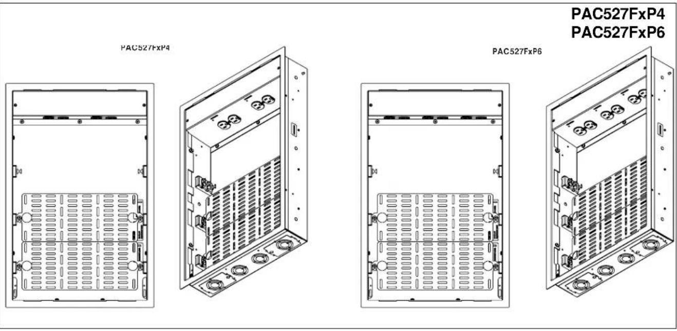
![PAC527FxPx *SEE PAC527F FOR ADDITIONAL BOX DIMENSIONS* AC LINE POWER CONDITIONER 125 V~, 60 Hz, 15 A 4x14 AWG STRANDED WIRE W/ ISOLATED GROUND SURGE PROTECTION EMI/RFI FILTERING POWER CONSUMPTION: <0.5 WATT USEABLE STORAGE SPACE 18.20 [462.3] 13.90 [353.0] 23.26 [590.9] 0.09 [2.4] 22.18 [563.4] 3.88 [98.4] DIMENSIONS: INCHES [MILLIMETERS]](/content/2026/05/1074158/images/705d55720b7713875751fe7819803d94be3e49cd0c32991ae6d31667e0d3623e.jpg)
DIMENSIONS - continued

![PAC527CVR-KIT 13.38 [339.7] 1.50 [38.0] 21.75 [552.5] 0.69 [17.5] 3.63 [92.1] 5.00 [127.0] 13.81 [350.8] DIMENSIONS: INCHES [MILLIMETERS]](/content/2026/05/1074158/images/e136418870762faadd4962515f2a3a3dc483c398236f8d3bf4e93c86e3c85cc8.jpg)
DIMENSIONS - continued
![PACPL1 0.50 [12.7] TYPICAL 1.50 [38.1] TYPICAL 0.95 [24.2] 0.20 [5.2] Ø 1.00 [25.4] FINGER HOLD BREAK-OFF LINE 10.00 [254.0] 1.25 [31.8] TYPICAL 5.00 [127.0] 12.00 [304.8] 13.21 [335.6] NOTE: SCREWS ARE THREADED TO THE BACKPLANE1. PACPL1 KIT INCLUDES TWO BACK PLANE PIECES AS2. SHOWN ABOVE DIMENSIONS: INCHES [MILLIMETERS]](/content/2026/05/1074158/images/6fa01440fb96f5c50377458e911d037f99843d92c634ce23081b56d35d406318.jpg)
PAC527 Series
Installation Instructions

- INSTALLATION INSTRUCTIONS
- In-Wall Box and Accessories
- DISCLAIMER
- DEFINITIONS
- IMPORTANT SAFETY INSTRUCTIONS
- --SAVE THESE INSTRUCTIONS--
- ADDITIONAL SAFETY INSTRUCTIONS SPECIFIC TO PAC527FxP4 / PAC527FxP6
- READ ALL INSTRUCTIONS BEFORE USING THIS PRODUCT!!!!
- DANGER: TO REDUCE THE RISK OF
- WARNING: TO REDUCE THE RISK OF
- WARNING: RISK OF ELECTRIC SHOCK!
- CAUTION: This equipment must be installed
- OPTIONAL PARTS PER CUSTOM CONFIGURATION (NOT INCLUDED)
- ADDITIONAL INFORMATION
- ASSEMBLY AND INSTALLATION
- Locating PAC527
- INSTRUCTIONS FOR PAC527FxP4 / PAC527FxP6 Only
- Isolated Ground Receptacle
- References
- Prepare for Wiring
- Outlet Box Use
- PAC527 Site Preparation
- PAC527 Box Preparation and Installation
- Installing Backplanes (PACPL1)
- Adding Template/Temporary Cover
- PAC527F-KIT
- PAC527CVR-KIT
Brand : Chief
Model : PAC527FW
Category : Wall socket