
AP7152B - Electric meter APC - Free user manual and instructions
Find the device manual for free AP7152B APC in PDF.


| Product Type | Electric Meter / Current Meter |
| Brand | APC by Schneider Electric |
| Model | AP7152B |
| Compatible Models | AP7155B, AP7175B |
| Mounting Options | Roof or vertical mounting rail inside enclosure |
| Included Mounting Hardware | 2 vertical mounting brackets, 4 pan head screws, 3 cable retention trays with 12 flat head screws and 24 wire ties |
| Display | Digital display showing current per phase (3-phase), cycles every 3 seconds |
| Control Button | Press to change displayed reading; press and hold for IP address, orientation settings |
| Phase Indicator LED | Green (normal), Yellow (warning), Red (alarm) |
| Network Interface | Ethernet port (RJ-45) for LAN connection |
| Serial Port | RJ-11 modular port for internal menu access |
| Status LED | Off (no power), Solid green (valid TCP/IP), Flashing green (invalid TCP/IP), Solid orange (hardware failure), Flashing orange (BOOTP requests) |
| Link LED | Indicates network activity |
| Power Supply | Power over Ethernet (PoE) |
| Reset Button | Resets the Current Meter without affecting attached devices |
| Warranty | 2-year factory warranty |
| Safety Warnings | Hazard of electric shock, explosion, or arc flash; use only supplied hardware |
| Additional Resources | User guide available at www.apc.com |
| Regulatory Compliance | Designed for use in IT environments |
Frequently Asked Questions - AP7152B APC
User questions about AP7152B APC
0 question about this device. Answer the ones you know or ask your own.
Ask a new question about this device
Download the instructions for your Electric meter in PDF format for free! Find your manual AP7152B - APC and take your electronic device back in hand. On this page are published all the documents necessary for the use of your device. AP7152B by APC.
USER MANUAL AP7152B APC
Installation Instructions

natural_image
Line drawing of a rectangular electronic component with two connected wires (no text or symbols)Customer support and warranty information is available at www.apc.com.
© 2016 Schneider Electric. APC, the APC logo and NetShelter are owned by Schneider Electric Industries, S.A.S. All rights reserved.
990-9943-001
6/2016
A
B

natural_image
Technical line drawing of a mechanical assembly with no visible text or symbols©

D

E

F

General Information
This section contains installation information for the following
equipment:
AP7152B, AP7155B, AP7175B
Additional Resources
The Current Meter User Guide contains complete operation and configuration information. Additional documentation and downloadable software and firmware is available on the applicable product page on the website www.apc.com. To quickly find a product page, enter the product name or part number in the Search field.
Inventory
| Quantity | Item |
| 1 | Configuration Cable |
| 3 | Cable retention trays with 12 flat head screws and 24 wire ties |
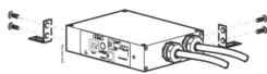
| 2 | Vertical mounting brackets with 4 pan head screws |
Mounting options
Install the Current Meter in one of the two following ways using the mounting brackets (provided): on the roof of the enclosure or on the inside of the enclosure mounted on the vertical mounting rails.
A DANGER
HAZARD OF ELECTRIC SHOCK, EXPLOSION, OR ARC FLASH To avoid possible electrical shock and equipment damage, use only the supplied hardware. Failure to follow these instructions will result in death or serious injury.
Roof
A Attach the two mounting brackets to the Current Meter with the screws (provided).
8 Attach the cage nuts (provided with your enclosure) to the inside of the roof. Secure the mounting brackets attached to the Current Meter to the cage nuts installed in the roof.
C You can mount multiple Current Meters on top of each other using additional mounting brackets (provided).
Vertical Mounting rail
D Attach the two mounting brackets to the back of the Current Meter with the screws (provided).
E Install the cage nuts (provided with your enclosure) into the vertical mounting rail.
Route the power cords to the top of the enclosure and through the roof.
Attach the brackets to the mounting rail with the screws (provided with your enclosure).
F The Display Interface
Configuring network settings and accessing the Current Meter
The Current Meter is DHCP compatible. Connect the network cable to the network port (6) and then apply power to the unit. When the status LED (7) for the network connection is solid green, perform the following to display the IP address.
If your network does not use a DHCP server, see the user's guide for your Current Meter for details on other methods for configuring the TCP/IP settings.
Press and hold the Control button ④ until "IP" appears on the display ⑦.
Release the Control Button and the IPv4 address will be scrolled across the display twice.
1 Phase indicator LED: Indicates normal (green), warning (yellow), or alarm (red) condition.
2 Reset button: Resets the Current Meter without affecting the attached devices.
9 Display of the current used by the Current Meter and attached devices:
• Shows the current being used per phase by the device attached to the Current Meter.
• Cycles through in 3-second intervals, and goes through all 3 readings (3 phases).
4 Control button:
- Press to change the reading of the current displayed on the digital display.
- Press and hold for five seconds to view the IP address of the Current Meter.
- Hold for an additional five seconds to view the orientation.
- Hold for an additional five seconds to change the orientation.
5 Serial port: Access internal menus by connecting this port (RJ-11 modular port) to a serial port on your computer, using the supplied serial cable (part number 940-0144A).
6 Ethernet port: Connects the Current Meter to your network, using a CAT-5 network cable.
7 Status LED: Indicates the status of the Ethernet LAN connection and the state of the Current Meter.
• Off—The Current Meter has no power.
- Solid green—The Current Meter has valid TCP/IP settings.
- Flashing green—The Current Meter does not have valid TCP/IP settings.
- Solid orange—A hardware failure has been detected in the Current Meter. Contact Customer Support at a phone number on the back cover of this manual.
- Flashing orange—The Current Meter is making BOOTP requests.
8 Link LED: Indicates whether there is activity on the network.
Two-Year Factory Warranty
This warranty applies only to the products you purchase for your use in accordance with this manual.
Terms of warranty
Schneider Electric warrants its products to be free from defects in materials and workmanship for a period of two years from the date of purchase. Schneider Electric will repair or replace defective products covered by this warranty. This warranty does not apply to equipment that has been damaged by accident, negligence or misapplication or has been altered or modified in any way. Repair or replacement of a defective product or part thereof does not extend the original warranty period. Any parts furnished under this warranty may be new or factory-remanufactured.
Non-transferable warranty
This warranty extends only to the original purchaser who must have properly registered the product. The product may be registered at www.apc.com.
Exclusions
Schneider Electric shall not be liable under the warranty if its testing and examination disclose that the alleged defect in the product does not exist or was caused by end user's or any third person's misuse, negligence, improper installation or testing. Further, Schneider Electric shall not be liable under the warranty for unauthorized attempts to repair or modify wrong or inadequate electrical voltage or connection, inappropriate on-site operation conditions, corrosive atmosphere, repair, installation, exposure to the elements, Acts of God, fire, theft, or installation contrary to Schneider Electric recommendations or specifications or in any event if the Schneider Electric serial number has been altered, defaced, or removed, or any other cause beyond the range of the intended use.
THERE ARE NO WARRANTIES, EXPRESSED OR IMPLIED, BY OPERATION OF LAW OR OTHERWISE, OF PRODUCTS SOLD, SERVICED OR FURNISHED UNDER THIS AGREEMENT OR IN CONNECTION HERewith. SCHNEIDER ELECTRIC DISCLAIMS ALL IMPLIED WARRANTIES OF MERCHANTABILITY, SATISFACTION AND FITNESS FOR A PARTICULAR PURPOSE. SCHNEIDER ELECTRIC EXPRESS WARRANTIES WILL NOT BE ENLARGED, DIMINISHED, OR AFFECTED BY AND NO OBLIGATION OR LIABILITY WILL ARISE OUT OF; SCHNEIDER ELECTRIC RENDERING OF TECHNICAL OR OTHER ADVICE OR SERVICE IN CONNECTION WITH THE PRODUCTS. THE FOREGOING WARRANTIES AND REMEDIES ARE EXCLUSIVE AND IN LIEU OF ALL OTHER WARRANTIES AND REMEDIES. THE WARRANTIES SET FORTH ABOVE CONSTITUTE SCHNEIDER ELECTRIC'S SOLE LIABILITY AND PURCHASER'S EXCLUSIVE REMEDY FOR ANY BREACH OF SUCH WARRANTIES. SCHNEIDER ELECTRIC WARRANTIES EXTEND ONLY TO PURCHASER AND ARE NOT EXTENDED TO ANY THIRD PARTIES.
IN NO EVENT SHALL SCHNEIDER ELECTRIC, ITS OFFICERS, DIRECTORS, AFFILIATES OR EMPLOYEES BE LIABLE FOR ANY FORM OF INDIRECT, SPECIAL, CONSEQUENTIAL OR PUNITIVE DAMAGES, ARISING OUT OF THE USE, SERVICE OR INSTALLATION, OF THE PRODUCTS, WHETHER SUCH DAMAGES ARISE IN CONTRACT OR TORT, IRRESPECTIVE OF FAULT, NEGLIGENCE OR STRICT LIABILITY OR WHETHER SCHNEIDER ELECTRIC HAS BEEN ADVISED IN ADVANCE OF THE POSSIBILITY OF SUCH DAMAGES. SPECIFICALLY, SCHNEIDER ELECTRIC IS NOT LIABLE FOR ANY COSTS, SUCH AS LOST PROFITS OR REVENUE, LOSS OF EQUIPMENT, LOSS OF USE OF EQUIPMENT, LOSS OF SOFTWARE, LOSS OF DATA, COSTS OF SUBSTITUENTS, CLAIMS BY THIRD PARTIES, OR OTHERWISE.
NO SALESMAN, EMPLOYEE OR AGENT OF SCHNEIDER ELECTRIC IS AUTHORIZED TO ADD TO OR VARY THE TERMS OF THIS WARRANTY. WARRANTY TERMS MAY BE MODIFIED, IF AT ALL, ONLY IN WRITING SIGNED BY AN SCHNEIDER ELECTRIC OFFICER AND LEGAL DEPARTMENT.
Warranty claims
Customers with warranty claims issues may access the Schneider Electric customer support network through the Support page of the website, www.apc.com/support. Select your country from the country selection pull-down menu at the top of the page. Select the Support tab to obtain contact information for customer support in your region.
Brand : APC
Model : AP7152B
Category : Electric meter