
MBM-CMM-001 - Computer Server Supermicro - Free user manual and instructions
Find the device manual for free MBM-CMM-001 Supermicro in PDF.


| Product Type | Server Management Module |
| Brand | Supermicro |
| Model | MBM-CMM-001 |
| Dimensions (W x D x H) | 6.6 x 5.2 x 0.8 inches (168 x 132 x 20 mm) |
| Weight | 0.35 lbs (160 g) |
| Power Consumption | 5W typical |
| Power Supply | DC 3.3V from motherboard standby power |
| Supported Interface | I2C, IPMB, SMBus |
| Management Features | Remote monitoring, system health, firmware updates |
| Chassis Compatibility | Supermicro server chassis with dedicated slot |
| Operating Temperature | 0°C to 50°C (32°F to 122°F) |
| Storage Temperature | -20°C to 70°C (-4°F to 158°F) |
| Humidity | 10% to 90% non-condensing |
| Certifications | FCC, CE, RoHS |
| Warranty | 1 year limited |
| Installation | Plug into dedicated header on motherboard |
| LED Indicators | Power, status, activity |
| Connectors | 10-pin header, RJ45 (optional) |
| Included Accessories | Quick installation guide |
| Maintenance | No user-serviceable parts; firmware update via IPMI |
Frequently Asked Questions - MBM-CMM-001 Supermicro
User questions about MBM-CMM-001 Supermicro
0 question about this device. Answer the ones you know or ask your own.
Ask a new question about this device
Download the instructions for your Computer Server in PDF format for free! Find your manual MBM-CMM-001 - Supermicro and take your electronic device back in hand. On this page are published all the documents necessary for the use of your device. MBM-CMM-001 by Supermicro.
USER MANUAL MBM-CMM-001 Supermicro
Web-based Management Utility

USER'S MANUAL
Revision 1.0d
The information in this USER'S MANUAL has been carefully reviewed and is believed to be accurate. The vendor assumes no responsibility for any inaccuracies that may be contained in this document, makes no commitment to update or to keep current the information in this manual, or to notify any person or organization of the updates. Please Note: For the most up-to-date version of this manual, please see our web site at www.supermicro.com.
Super Micro Computer, Inc. ("Supermicro") reserves the right to make changes to the product described in this manual at any time and without notice. This product, including software, if any, and documentation may not, in whole or in part, be copied, photocopied, reproduced, translated or reduced to any medium or machine without prior written consent.
IN NO EVENT WILL SUPERMICRO BE LIABLE FOR DIRECT, INDIRECT, SPECIAL, INCIDENTAL, SPECULATIVE OR CONSEQUENTIAL DAMAGES ARISING FROM THE USE OR INABILITY TO USE THIS PRODUCT OR DOCUMENTATION, EVEN IF ADVISED OF THE POSSIBILITY OF SUCH DAMAGES. IN PARTICULAR, SUPERMICRO SHALL NOT HAVE LIABILITY FOR ANY HARDWARE, SOFTWARE, OR DATA STORED OR USED WITH THE PRODUCT, INCLUDING THE COSTS OF REPAIRING, REPLACING, INTEGRATING, INSTALLING OR RECOVERING SUCH HARDWARE, SOFTWARE, OR DATA.
Any disputes arising between manufacturer and customer shall be governed by the laws of Santa Clara County in the State of California, USA. The State of California, County of Santa Clara shall be the exclusive venue for the resolution of any such disputes. Supermicro's total liability for all claims will not exceed the price paid for the hardware product.
FCC Statement: This equipment has been tested and found to comply with the limits for a Class A digital device pursuant to Part 15 of the FCC Rules. These limits are designed to provide reasonable protection against harmful interference when the equipment is operated in a commercial environment. This equipment generates, uses, and can radiate radio frequency energy and, if not installed and used in accordance with the manufacturer's instruction manual, may cause harmful interference with radio communications. Operation of this equipment in a residential area is likely to cause harmful interference, in which case you will be required to correct the interference at your own expense.
California Best Management Practices Regulations for Perchlorate Materials: This Perchlorate warning applies only to products containing CR (Manganese Dioxide) Lithium coin cells. Perchlorate Material-special handling may apply. See www.dtsc.ca.gov/hazardouswaste/perchlorate for further details.
HANDLING OF LEAD SOLDER MATERIALS USED IN THIS PRODUCT MAY EXPOSE YOU TO LEAD, A CHEMICAL KNOWN TO THE STATE OF CALIFORNIA TO CAUSE BIRTH DEFECTS AND OTHER REPRODUCTIVE HARM.
Manual Revision 1.0d
Release Date: November 23, 2016
Unless you request and receive written permission from Super Micro Computer, Inc., you may not copy any part of this document.
Information in this document is subject to change without notice. Other products and companies referred to herein are trademarks or registered trademarks of their respective companies or mark holders.
Copyright © 2016 by Super Micro Computer, Inc.
All rights reserved.
Printed in the United States of America
Preface
About this Manual
This manual is written for professional system integrators, Information Technology professionals, service personnel and technicians. It provides information for the use of Supermicro's MicroBlade Web-based Management Utility.
Manual Organization
Chapter 1: Introduction
The first chapter provides an introduction about the Web-based Management Utility.
Chapter 2: Blade System
This chapter covers the menu options and controls for the Blade System menu.
Chapter 3: System Health
This chapter covers the menu options and controls for the System Health menu.
Chapter 4: Configuration
This chapter covers the menu options and controls for the Configuration menu.
Chapter 5: Remote Console
This chapter covers the use of the Remote Console menu.
Chapter 6: Maintenance
This chapter covers the use of the Maintenance menu.
Contacting Supermicro
Headquarters
Address: Super Micro Computer, Inc.
980 Rock Ave.
San Jose, CA 95131 U.S.A.
Tel: +1 (408) 503-8000
Fax: +1 (408) 503-8008
marketing@supermicro.com (General Information)
Email: support@supermicro.com (Technical Support)
Web Site: www.supermicro.com
Europe
Address: Super Micro Computer B.V.
's-Hertogenbosch, The Netherlands
Tel: +31 (0) 73-6400390
Fax: +31 (0) 73-6416525
sales@supermicro.nl (General Information)
Email: support@supermicro.nl (Technical Support)
rma@supermicro.nl (Customer Support)
Asia-Pacific
Address: Super Micro Computer, Inc.
3F, No. 150, Jian 1st Rd.
Zhonghe Dist., New Taipei City 23511
Taiwan (R.O.C)
Tel: +886-(2) 8226-3990
Fax: +886-(2) 8226-3992
Web Site: www.supermicro.com.tw
Technical Support:
Email: support@supermicro.com.tw
Tel: +886-(2)-8226-3990
Table of Contents
Chapter 1 Introduction....1-1
1-1 Network Connection/Login....1-1
Reset....1-2
Address Defaults....1-2
1-2 Page Elements and Controls....1-2
Main Menu Buttons....1-3
Chapter 2 Blade System ...... 2-1
2-1 Blade System Summary Page 2-1
2-2 Blade Status Page 2-2
Node Status Page....2-4
Node Status – Summary Pane......2-4
Node Status – Sensor Reading Pane ......2-6
Node Status – Network Settings Pane......2-7
Node Status – Event Log Pane......2-8
Node Status – FRU Information Page....2-9
Node Status – Date & Time Page 2-10
Node Status – Power/Temperature Record Page....2-11
Node Status – Node Product Key Page....2-12
Node Status – Hardware Information Page ......2-13
2-3 Power Supply Page 2-14
Power Supply Status Page 2-15
Power Supply Status—Summary Pane....2-15
Power Supply Status – FRU Information Page....2-16
2-4 Switch Module Page....2-17
Switch Module Status Page....2-18
Switch Module Status– Summary Pane....2-18
Switch Module Status – FRU Information Page....2-19
2-5 CMM Page 2-20
2-6 FRU Information 2-22
Chapter 3 System Health....3-1
3-1 Sensor Readings Page 3-1
3-2 System Event Log Page....3-3
3-3 Power/Temperature Record Page....3-5
Chapter 4 Configuration 4-1
4-1 Alerts Page 4-2
4-2 Date and Time Page....4-3
4-3 LDAP Page....4-5
4-4 Active Directory Page 4-6
Active Directory - Advanced Settings Page 4-8
4-5 RADIUS Page....4-9
4-6 CMM Network Page....4-10
4-7 Blade IPMI Network Page....4-12
4-8 Dynamic DNS Page 4-14
4-9 SMTP Page 4-15
4-10 SNMP Page 4-16
4-11 SSL Certification Page 4-18
4-12 Users Page 4-19
4-13 Port Page 4-20
4-14 IP Access Control Page 4-21
4-15 Web Session Page 4-22
4-16 SMC RAKP Page 4-23
4-17 Auto Update Redundant CMM Page 4-24
Chapter 5 Remote Console....5-1
5-1 Console Redirection Page 5-1
5-2 Launch SOL 5-2
Chapter 6 Maintenance....6-1
6-1 CMM Firmware Update Page....6-1
6-2 CMM Unit Reset Page....6-2
6-3 Factory Default Page....6-3
6-4 CMM Configuration Page....6-4
6-5 System Event Log Page....6-5
6-6 UID Control Page 6-6
Appendix A Checking the MAC Address.....A-A
List of Figures
Figure 1-1. Home Page....1-2
Figure 2-1. Blade System Summary Page....2-1
Figure 2-2. Blade Status Page....2-2
Figure 2-3. Blade Status Page – Summary Pane ......2-4
Figure 2-4. Blade Status Page – Node Sensor Reading Pane ...... 2-6
Figure 2-5. Blade Status Page – Blade IPMI Network Pane....2-7
Figure 2-6. Blade Status Page – Event Log Pane ......2-8
Figure 2-7. Blade Status Page – FRU Information Pane ......2-9
Figure 2-8. Blade Status Page – Date & Time Pane....2-10
Figure 2-9. Blade Status Page – Power/Temperature Record Pane ......2-11
Figure 2-10. Blade Status Page – Node Product Key Pane ......2-12
Figure 2-11. Blade Status Page – Hardware Information Pane ......2-13
Figure 2-12. Power Supply Status Page – Summary Pane ......2-14
Figure 2-13. Power Supply Status Page – Summary Pane ......2-15
Figure 2-14. Power Supply Status Page – FRU Information Pane ......2-16
Figure 2-15. Switch Module Page....2-17
Figure 2-16. Switch Module Page – Summary Pane ...... 2-18
Figure 2-17. Switch Module Page – FRU Information Pane ...... 2-19
Figure 2-18. CMM Status Summary Page 2-20
Figure 2-19. CMM Status – FRU Information Page ......2-21
Figure 2-20. Blade System – Middle Plane FRU Information Page ......2-22
Figure 3-1. Sensor Readings Page....3-1
Figure 3-2. System Event Log Page....3-3
Figure 3-3. Event Log – Advanced Settings Page....3-4
Figure 3-4. System Event Log Page 3-5
Figure 4-1. Blade Status Page....4-2
Figure 4-2. Modify Alert Page 4-3
Figure 4-3. Date and Time Page....4-3
Figure 4-4. LDAP Page....4-5
Figure 4-5. Active Directory Page 4-6
Figure 4-6. Add Role Group Page....4-7
Figure 4-7. Modify Role Group Page 4-7
Figure 4-8. Active Directory - Advanced Settings Page....4-8
Figure 4-9. RADIUS Page....4-9
Figure 4-10. CMM NetworkPage....4-10
Figure 4-11. Blade IPMI Network Page....4-12
Figure 4-12. Dynamic DNS Page....4-14
Figure 4-13. SMTP Page 4-15
Figure 4-14. SNMP Page....4-16
Figure 4-15. Add New SNMPv3 User Screen....4-17
Figure 4-16. Modify SNMPv3 User Screen....4-17
Figure 4-17. SSL Certification Page....4-18
Figure 4-18. Users Page....4-19
Figure 4-19. Port Setting Page....4-20
Figure 4-20. IP Access Control Page....4-21
Figure 4-21. Web Session Page 4-22
Figure 4-22. SMC RAKP Page....4-23
Figure 4-23. Auto Update Redundant CMM Page 4-24
Figure 5-1. Console Redirection Page 5-1
Figure 5-2. SOL Console Page....5-2
Figure 6-1. Update Firmware Page....6-1
Figure 6-2. Unit Reset Page....6-2
Figure 6-3. Factory Default Page....6-3
Figure 6-4. CMM Configuration Page 6-4
Figure 6-5. List of System Event Log Page....6-5
Figure 6-6. List of System Event Log Page....6-6
Figure A-1. Checking the MAC Address using the Command Line Interface .. A-A
List of Tables
Table 1-1. Address Defaults....1-2
Table 1-2. Home Page Elements and Controls....1-3
Table 1-3. Main Menu Buttons....1-3
Table 2-1. Blade Status Page Controls....2-3
Table 2-2. Blade Status Page – Summary Pane Controls....2-5
Table 2-3. Blade Status Page – Node Sensor Reading Pane Controls......2-6
Table 2-4. Blade Status Page – Network Settings Pane Controls ...... 2-7
Table 2-5. Blade Status Page – Event Log Pane Controls ......2-8
Table 2-6. Blade Status Page – Date & Time Pane Controls ......2-10
Table 2-7. Blade Status Page – Power/Temperature Record Pane Controls.2-11
Table 2-8. Blade Status Page – Node Product Key Pane Controls ......2-12
Table 2-9. Power Supply Status Page – Summary Pane Controls ...... 2-14
Table 2-10. Power Supply Status Page – Summary Pane Controls......2-15
Table 2-11. Switch Module Page Controls....2-17
Table 2-12. Switch Module Page – Summary Pane Controls ...... 2-19
Table 2-13. CMM Status – Summary Page Controls....2-20
Table 3-1. Sensor Readings Page Controls....3-2
Table 3-2. System Event Log Page Controls....3-3
Table 3-3. System Event Log Page Controls....3-5
Table 4-1. Blade Status Page Controls....4-2
Table 4-2. Date and Time Page Controls....4-4
Table 4-3. LDAP Page Controls....4-5
Table 4-4. Active Directory Page Controls....4-6
Table 4-5. RADIUS Page Controls....4-9
Table 4-6. CMM Network Page Controls 4-11
Table 4-7. Blade IPMI Network Page Controls 4-13
Table 4-8. Dynamic DNS Page Controls....4-14
Table 4-9. SMTP Page Controls 4-15
Table 4-10. SNMP Page Controls....4-16
Table 4-11. SSL Certification Page Controls .... 4-18
Table 4-12. Users Page Controls....4-19
Table 4-13. Port Setting Page Controls .... 4-20
Table 4-14. IP Access Control Page Controls....4-21
Table 4-15. Web Session Page Controls....4-22
Table 4-16. SMC RAKP Page Controls 4-23
Table 4-17. Auto Update Redundant CMM Page Controls....4-24
Table 5-1. Console Redirection Page Controls....5-2
Notes
Table 5-2. SOL Console Page Controls....5-2
Chapter 1 Introduction
The MicroBlade Web-based Management Utility is a web-based interface that consolidates and simplifies system management for Supermicro MicroBlade systems. The MicroBlade Web-based Management Utility aggregates and displays data from the SIMCM (the IPMI card designed for Supermicro's MicroBlade Chassis Management Module).
The MicroBlade Web-based Management Utility provides the following key management features:
- Enables IT administrators to view in-depth hardware configuration and status information using a single intuitive interface.
- Provides an OS-independent, remote graphical console.
- Allows remote users to map local media (floppy, CD-ROM, removable disks and hard drives) or ISO images on a shared network drive to a blade server.
Supported Browsers
The following browsers have been tested for use with the MicroBlade Web-based Management Utility. It is recommended that you use the most current revision of the browser you choose. The minimum browser revisions supported by the MicroBlade Web-based Management Utility are shown below:
- Internet Explorer 7
- Firefox 2.0.0.7
- Netscape 9.03b
- Google Chrome
1-1 Network Connection/Login
To log into the MicroBlade Web-based Management Utility:
- Launch a web browser.
-
In the address field of the browser, enter the IP address that you assigned to the MicroBlade Chassis Management Module (CMM) and hit the
key. -
When the browser makes contact with MicroBlade Chassis Management Module, enter your username and password, then click LOGIN.
-
The WEB-BASED MANAGEMENT UTILITY HOME PAGE will then display as shown in Figure 1-1.
Reset
To reset the Web-based Management Utility simply press push a pen tip into the reset hole in the back of the CMM module. This will reset the system. See the MicroBlade Network Modules User's Manual for further details.
Address Defaults
Table 1-1 shows the default addresses that are initially set for the CMM. Afterwards, you can change these values within the program (see Chapter 4).
Table 1-1. Address Defaults
| Default Description | |
| Default IP Address https://192.168.100.100 | |
| Default Gateway Address 0.0.0.0 | |
| Default Subnet Mask 255.255.255.0 | |
| Default username ADMIN | |
| Default password ADMIN | |
1-2 Page Elements and Controls
Figure 1-1 and Table 1-2 respectively display a WEB-BASED MANAGEMENT UTILITY HOME PAGE elements and its controls.
Figure 1-1. Home Page
![SERMIC MicroBlade CMS CMS Name: IP Address : 172.31.0.158 Use: ADDITION : [Administrator] Name: [Adobe-Goosed English] Blade System System Health Configuration Remote Control Maintenance Help Blade Systems Summary Blade Status Power Supply Switch Module CMM FXI Information Summary Summary Module Nam…](/content/2026/05/1074119/images/8201b624a8c5be6f593f7184d3d485eae238d9d79442805ee066ec95cacd6b70.jpg)
Table 1-2. Home Page Elements and Controls
| Item Name Description | ||
| 1 Host | Identification | This displays the host identification information including host server IP address and user ID. |
| 2 Page | Controls | Control links for page refresh and logout are found here in the upper right corner of the page. Additionally, there is a LANGUAGE drop-down list box for selecting the language used. |
| 3 Menu | Bar | This menu bar contains control buttons for the MicroBlade Web-based Management Utility's menus. Clicking on a button brings up the summary page for that menu, plus the menu items listed in the MENU LIST Pane on the left. Also placing the cursor over these buttons brings up a drop-down list of all the menu items for that menu that allow you to select one of them. |
| 4 Menu | List Pane | This is a list of links for each menu item from a selected menu from the MENU BAR. Clicking on one of these links brings up the control pane for that menu item and its controls. |
| 5 Control Pane | This pane controls for the menu item selected from the menu bar. You can use these controls to configure and control blade modules, other equipment or services for your MicroBlade. | |
| 6 Help | Display Box | This text display box contains help information for the page you have selected. To activate help, press the HELP button to toggle on or off the HELP DISPLAY box. |
Main Menu Buttons
The buttons below in Table 1-3 cover the main functions of MicroBlade Web-based Management Utility. Clicking on an button will reveal a menu of related functions that you can select. Clicking on a button will bring up a summary page for that menu with all the menu items shown in the right pane of the page. These you click on to go their pages.
Table 1-3. Main Menu Buttons
| Menu Buttons Description | |
| Blade System These pages contains general information about the blade system. | |
| System Health | These pages shows you data related to the server's health, such as sensor readings and the event log. |
| Configuration | Use these pages to configure various settings, such as alerts, users, or network etc. |
| Remote Control | These pages allows you to perform various remote operations on the server, such as launching the remote console. |
| Maintenance | Use these pages to maintain the IPMI device, such as update firmware or reset the IPMI device. |
| Help | This button toggles on or off the HELP DISPLAY box on the page. |
Notes
Chapter 2 Blade System
The BLADE SYSTEM menu allows you to access and configure the various blades in your system. Clicking the BLADE SYSTEM icon allows you to access the following pages through its sub-menus:
- Blade System Summary Page
- Blade Status Page
• Power Supply Page - Switch Module Page
• CMM Page - FRU Information
2-1 Blade System Summary Page
Figure 2-1. Blade System Summary Page

This page (Figure 2-1) displays a summary status of all blades and nodes, switch modules and power supplies. The CONTROL pane displays a column for each module's error status. Press the REFRESH button to refresh the view on this page.
2-2 Blade Status Page
The BLADE STATUS page allows you to check and set up the status of all the blade modules in the system and displays information in columns of a table including Blade, Name, Model, Power Status, Maximum Power, KVM, UID, Error, BMC IP, BMC Version, Power Fail Policy and AC Lost Policy
Function buttons at the top of the table include Power On/Off, Power Cycle, Power Reset, Graceful Shutdown, AC cycle, Power Fail Policy, AC Lost Policy and Refresh of the blade module. Selecting a blade module or node from the blade table, and then pushing a function button at the top of the table changes the status and functions of the blade module. There are also control buttons and drop-down list box controls within the table for changing status on a blade module as well.
The command functions on the page and in some of the columns allow you to perform various functions, as shown in Figure 2-2 and described in Table 2-1.
To perform a function, first click the box(es) next to the blade(s) or node(s) you wish to issue a command to and then click the command button on top of the table. You can also click on any of the individual nodes listed to bring up additional pages with details about that particular node's status, and the controls for setting them (see "Node Status Page" on page 2-4).
Figure 2-2. Blade Status Page

Table 2-1. Blade Status Page Controls
| Item | Control Name Description | |
| 1 Power | Off Button | Checking the check box next to a node or blade module and then pressing this button will power off the selected node or blade system. |
| 2 Power | On Button | Checking the check box next to a node or blade module and then pressing this button will power on the selected node or blade system. |
| 3 Power | Cycle Button | Checking the check box next to a node or blade module and then pressing this button will initiate the power cycle for the selected node or blade system. |
| 4 Power | Reset Button | Checking the check box next to a node or blade module and then pressing this button will reset the selected node or blade system. |
| 5 | Graceful Shutdown Button | Checking the check box next to a node or blade module and then pressing this button will initiate a graceful shutdown for the selected node or blade system. |
| 6 AC Cycle | Button | Checking the check box next to a node or blade module and then pressing this button will initiate the AC cycle for the selected node or blade system. |
| 7 | Power Fail Policy Button | Checking the check box next to a node or blade module, and then selecting an option from the drop-down list box for the item and then pressing this button will set the selected power fail policy for the selected node or blade system. |
| 8 Pwr | Capping Button | Checking this button for a selected node or blade module sets power capping for that node or blade by bringing up a confirmation pop-up. |
| 9 AC Lost Policy | Button | Checking the button next to a node or blade module, and then selecting an option from the drop-down list box for the item and then pressing this button will set the selected AC lost policy for the selected node or blade system. |
| 10 Refresh | Button | Pressing this button will refresh the screen to accurately show the new status of all blade modules or nodes in the system. |
| 11 Pwr | Status On/Off | The button in this column allows you to power on or off a node or blade in the selected row. |
| 12 KVM | Pressing the button in this column for a selected blade or node starts up a KVM window for viewing that blade or node. | |
| 13 UID | Pressing the button in this column for a selected blade lights up the UID for that blade. | |
| 14 Pwr | Fail Policy | This column contains a pull-down menu for selecting the Power Fail Policy for the selected blade or node. Options include THROTTLE, POWEROFF or PERFORMANCE. |
| 15 Pwr | Cap | This column contains a pull-down menu for selecting the Power Cap for the selected blade or node. Options include READ ONLY, DISABLED, and percentage values from 50% to 90%. |
| 16 AC Lost Policy | This column contains a pull-down menu for selecting the AC Lost Policy for the selected blade or node. Options include POWEROFF, POWERON and LASTSTATE. | |
Node Status Page
If you click on the link for a node in the BLADE STATUS page, a new window will appear with the first of several pages with additional controls for that specific node in your system. The following control panes can be selected for this window by clicking on links that are available at the top of the CONTROL pane in the new window:
- Node Status – Summary Pane
- Node Status – Sensor Reading Pane
- Node Status – Network Settings Pane
- Node Status – Event Log Pane
- Node Status – FRU Information Page
- Node Status – Date & Time Page
Node Status – Summary Pane
Clicking on the SUMMARY link brings up a SUMMARY pane (Figure 2-3) with controls that are listed and described in Table 2-2.
Figure 2-3. Blade Status Page – Summary Pane
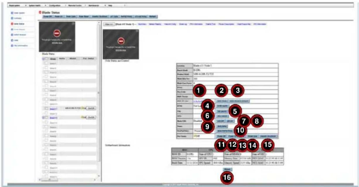
Table 2-2. Blade Status Page – Summary Pane Controls
| Item Name Description | ||
| 1 BMC | IP Address Link | Pressing this link brings up the SYSTEM SUMMARY page (Figure 2-1) that displays information about the selected node or blade module, a REMOTE CONSOLE PREVIEW pane and the following controls for the pane and system:REFRESH PREVIEW IMAGEPOWER DOWN/ONRESETClicking on the FRU Information link reveals static display FRU information about the selected blade module or node selected. |
| 2 BMC | Reset Button Pressing this button resets the BMC. | |
| 3 | BMC Reset To Default Button | Pressing this button resets the BMC settings to their default settings. |
| 4 KVM | Launch Button Press this button to launch a KVM Remote window. | |
| 5 VM | Launch Button Press this button to launch a V IRTUAL MEDIA SETUP window. | |
| 6 | SOL Launch Button | Press this button to launch a SOL REMOTE window. |
| 7 UID | Off Button | Use this button to turn off the UID LED for a selected node or blade module. |
| 8 UID | On Button | Use this button to light up the UID LED for a selected node or blade module. |
| 9 | Save Name Field and Button | Enter a name in the field provided and press the SAVE NAME button to apply the new name to the node or blade module. |
| 10 | Save Power Fail Policy Button and Drop-down List Box | This drop-down list box is used to set the Power Fail Policy and includes the following items you may set for this policy:POWER OFFTHROTTLEPERFORMANCEAfter selecting the Power Fail Policy from the drop-down list box, press the SAVE PWRFAIL POLICY button to apply it. |
| 11 | Power On Button Pressing this button will power on the selected node or blade system. | |
| 12 | Power Off Button | Pressing this button will power off the selected node or blade system. |
| 13 | Reset Button Pressing this button will reset the selected node or blade system. | |
| 14 | Power Cycle Button | Pressing this button will initiate the power cycle for the selected node or blade system. |
| 15 | Graceful Shutdown Button | Pressing this button will initiate a graceful shutdown for the selected node or blade system. |
| 16 | Refresh Button | Pressing this button refreshes the page display. |
Node Status – Sensor Reading Pane
Clicking on the SENSOR READING link brings up a NODE SENSOR READING pane (Figure 2-4) with controls that are listed and described in Table 2-3.
Figure 2-4. Blade Status Page – Node Sensor Reading Pane

Table 2-3. Blade Status Page – Node Sensor Reading Pane Controls
| Item Name Description | ||
| 1 | Select Sensors List Box | Use this list box to select the types of sensors you wish to view. Options include ALL SENSORS, TEMPERATURE SENSORS, VOLTAGE SENSORS or WATCHDOG 2. |
| 2 Refresh Button Press this button to refresh the page. | ||
| 3 | Show Thresholds Button | Pressing this button shows the thresholds for your system. |
Node Status – Network Settings Pane
Clicking on the NETWORK CONFIG link brings up a Blade IPMI NETWORK pane (Figure 2-5) with controls that are listed and described in Table 2-4.
Figure 2-5. Blade Status Page – Blade IPMI Network Pane
![Blade Status [Power Off] - Power On | Power Cycle | Power Reset | Grantee Shockwave | AF Cycle | Perfect Policy | Pan Scaling | AQLnet Policy | Refresh Blade Status Blade Name Mk Blade A1 3.00E-6412 Blade 1 3.00E-6412 Blade 2 3.00E-6412 Blade 3 3.00E-6412 Blade 4 3.00E-6412 Blade A2 3.00E-6412 Blade…](/content/2026/05/1074119/images/b1dac2826b257a0c5b3641513db17c551b333443861dab09e7681ef15cffc361.jpg)
Table 2-4. Blade Status Page – Network Settings Pane Controls
| Item Name Description | ||
| 1 Hostr | Name Field Enter a host | name in this field if desired. |
| 2 IPv4 | Settings | The IPv4 settings can be configured with these controls when you select the USE THE FOLLOWING IP ADDRESS (USE STATIC MODE) option button. |
| 3 IPv6 | Settings The IPv6 settings | can be configured using these controls. |
| 4 | VLAN Enable/Disable | These option buttons allow you to enable or disable VLAN. |
| 5 RMCP | Port Field The port setting for RMCP can be entered in the field provided here. | |
| 6 Save | Button | Pressing the SAVE button saves the configuration for the selected node or blade module. |
Node Status – Event Log Pane
Clicking on the EVENT LOG link brings up a EVENT LOG pane (Figure 2-6) with controls that are listed and described in Table 2-5.
Figure 2-6. Blade Status Page – Event Log Pane
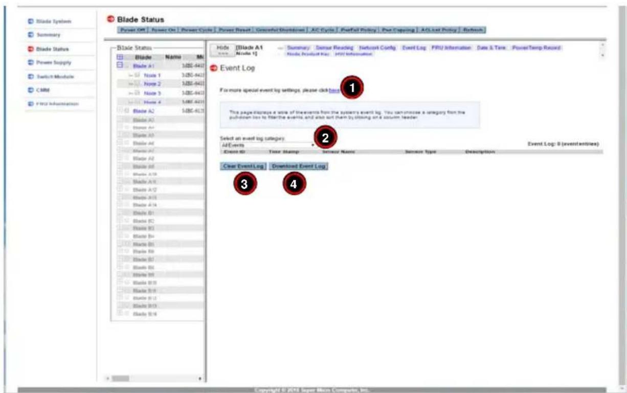
Table 2-5. Blade Status Page – Event Log Pane Controls
| Item Name Description | ||
| 1 | Specific Event Logs Link | Clicking on this link brings up a new pane where you can specify specific events to log into the Event Log. |
| 2 | Select an Event Log Category Drop-down Link Box | This link box contains options for specifying the type of events to view in the pane. The following options are available:All EventsBIOS Generated EventsSystem Management Software EventsSensor Specific Events |
| 3 | Clear Event Log Button | Press this button to clear the event log of all entries. |
| 4 | Download Event Log Button | Press this button to download the event log. |
Node Status – FRU Information Page
Clicking on the FRU INFORMATION link brings up a FRU INFORMATION pane (Figure 2-7) with static FRU Information about the node or blade module selected.
Figure 2-7. Blade Status Page – FRU Information Pane

Node Status – Date & Time Page
Clicking on the DATE & TIME link brings up a DATE & TIME pane (Figure 2-8) with controls that are listed and described in Table 2-6.
Figure 2-8. Blade Status Page – Date & Time Pane

Table 2-6. Blade Status Page – Date & Time Pane Controls
| Item Name Description | ||
| 1 | Time Update Mode Option Buttons | Using these option buttons, you may select either NTP, Local or CMM mode for time updates to the system. Each mode, when selected, activates or deactivates fields or drop-down list boxes for specifying date and time information or the primary or secondary NTP server. |
| 2 | Daylight Savings Time check box | Click this check box if you wish to use daylight savings time for your time settings. |
| 3 | Apply Above Settings to All Blades check box | Use this check box to apply all time and date settings to ALL blades and nodes in your system rather than just the selected blade or node. |
| 4 Refresh Button Press this button to refresh the page. | ||
| 5 Save Button | Pressing the SAVE button saves the configuration for the selected node or blade module. | |
Node Status – Power/Temperature Record Page
Clicking on the POWER/TEMP RECORD link brings up a POWER/TEMPERATURE RECORD pane (Figure 2-9) with controls that are listed and described in Table 2-7. This pane contains tables for power and temperature information as well as graphs for Last Hour, Last Day, Last Week displaying this information below the tables (not shown).
Figure 2-9. Blade Status Page – Power/Temperature Record Pane
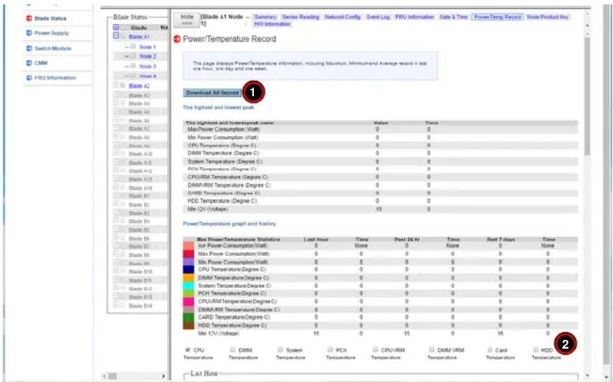
Table 2-7. Blade Status Page – Power/Temperature Record Pane Controls
| Item Name Description | ||
| 1 | Download All Record Button | Pressing this button brings up window you can use to download all power and temperature information to a file on your system. |
| 2 | Temperature Check Boxes | Clicking these check boxes displays the selected temperature information in the graphs below. |
Node Status – Node Product Key Page
Clicking on the NODE PRODUCT KEY link brings up a NODE PRODUCT KEY pane (Figure 2-10) with controls that are listed and described in Table 2-8.
Figure 2-10. Blade Status Page – Node Product Key Pane

Table 2-8. Blade Status Page – Node Product Key Pane Controls
| Item Name Description | ||
| 1 | Node Product Key Field | Enter the Node Product Key here in order to enable the BIOS update feature. |
Node Status – Hardware Information Page
Clicking on the HW INFORMATION link brings up a HARDWARE INFORMATION pane (Figure 2-11) with hardware information displayed.
Figure 2-11. Blade Status Page – Hardware Information Pane

2-3 Power Supply Page
Click a POWER SUPPLY to reveal the POWER SUPPLY STATUS page (Figure 2-12). You can use the commands listed in Table 2-9 to control the power supplies in your system.
To perform a function, first click the box(es) next to the power supplies you wish to issue a command to and then click the command icon you wish to use. You can also click on any of the individual power supplies listed to bring up additional pages with details about that particular power supply's status, and the controls for setting them (see "Power Supply Status Page" on page 2-15).
Figure 2-12. Power Supply Status Page – Summary Pane
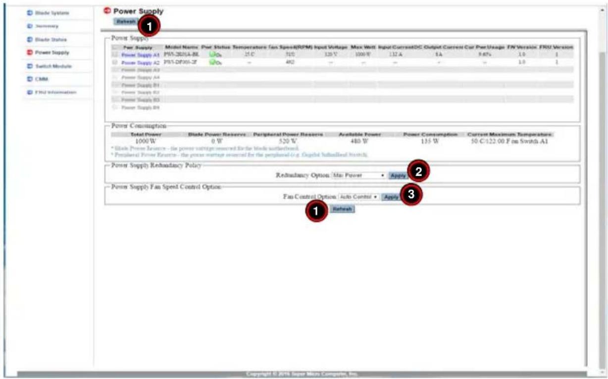
Table 2-9. Power Supply Status Page – Summary Pane Controls
| Item Name Description | ||
| 1 Refresh Buttons Pressing either of these buttons refreshes the page display. | ||
| 2 Redundancy Controls | These controls allow you to select the Redundancy Option for your system. Select either the Max Power, Redundancy N+1 or Redunancy N+N option from the pull-down menu and press the Apply button to apply your redundancy option to the system. | |
| 3 | Fan Control Option Controls | These controls allow you to select the Fan Control Option for your system. Select either the User Control or Auto Control option from the pull-down menu and press the Apply button to apply your fan control option to the system. |
Power Supply Status Page
If you click on the link for a power supply in the POWER SUPPLY page, a new window will appear with the first of two pages with additional controls for that specific power supply in your system. The following CONTROL panes can be selected for this window by clicking on links that are available at the top of the CONTROL pane in the new window:
• Power Supply Status—Summary Pane
- Power Supply Status – FRU Information Page
Power Supply Status—Summary Pane
Clicking on the SUMMARY link brings up a POWER SUPPLY SUMMARY pane (Figure 2-13) with controls that are listed and described in Table 2-10.
Figure 2-13. Power Supply Status Page – Summary Pane

Table 2-10. Power Supply Status Page – Summary Pane Controls
| Item Name Description | ||
| 1 Refresh Button Pressing this button refreshes the page display. | ||
| 2 | Fan ControlOption Controls | These controls allow you to select the Fan Control Option for your system.Select either the User Control or Auto Control option from the pull-down menu and press the Apply button to apply your fan control option to the system. |
Power Supply Status – FRU Information Page
Clicking on the FRU INFORMATION link brings up a FRU INFORMATION pane (Figure 2-14) with static FRU information about the Power Supply module selected.
Figure 2-14. Power Supply Status Page – FRU Information Pane

2-4 Switch Module Page
Click on SWITCH MODULE to reveal the SWITCH MODULE STATUS page (Figure 2-15). You can use the commands listed in Table 2-11 to control the power supplies in your system.
To perform a function, first click the box(es) next to the power supplies you wish to issue a command to and then click the command icon you wish to use. You can also click on any of the individual power supplies listed to bring up additional pages with details about that particular power supply's status, and the controls for setting them (see "Switch Module Status Page" on page 2-18).
Figure 2-15. Switch Module Page

Table 2-11. Switch Module Page Controls
| Item Name Description | ||
| 1 HW Reset Button | Press this button to reset a selected switch to its default configuration. The reset button will reset all switch configurations, including IP address and so on. | |
| 2 | UID On Button | Press this button to turn on a UID for a selected switch. |
| 3 UID Off Button Press this button to turn off a UID for a selected switch. | ||
| 4 Refresh Button | Click this icon to refresh the page and update the status of a switch shown. | |
| 5 UID Button | Press this button in the UID column to turn on or off a UID for a selected switch. | |
NOTE: Initially, you must manually enter the IP address for each switch to gain access to it. Each IP address should be unique when there are multiple switches on the same network segment.
Switch Module Status Page
If you click on the link for a switch module in the SWITCH MODULE page, a new window will appear with the first of two pages with additional controls for that specific power supply in your system. The following CONTROL panes can be selected for this window by clicking on links that are available at the top of the CONTROL pane in the new window:
- Switch Module Status– Summary Pane
- Switch Module Status – FRU Information Page
Switch Module Status—Summary Pane
Clicking on the SUMMARY link brings up a SWITCH MODULE SUMMARY pane (Figure 2-16) with controls that are listed and described in Table 2-12.
Figure 2-16. Switch Module Page – Summary Pane
![Switch Module HW Reset | USD On | USD Off | Refresh Switch Switch Switch Tube Module Switch A1 Gupta Break 32054-4 Switch A2 Switch B1 Switch B2 Switch Module Switch Information Breaks Break Type Module Name Per Status Temperature USD Error Management IP FV Var [Switch A1] Gupta Break 32054-4-G6316-…](/content/2026/05/1074119/images/56ead40bfae5a8370c443755e9b3388c9ea72e2242e54f60387e3e8790ef48ad.jpg)
Table 2-12. Switch Module Page – Summary Pane Controls
| Item Name Description | ||
| 1 HW | Reset Button | Press this button to reset a selected switch to its default configuration. The reset button will reset all switch configurations, including IP address and so on. |
| 2 | UID On Button | Press this button to turn on a UID for a selected switch. |
| 3 UID | Off Button Press this button to turn off a UID for a selected switch. | |
| 4 Refresh | Button Pressing this button refreshes the page display. | |
| 5 | Configure Date and Time Settings Section | Use this section to configure the date and time settings for your selected switch. Enter the time and date settings in the field provided and then press the SAVE button. |
| 6 | Switch Network Configuration Section | Use this section to configure the selected switches IP addresses (IP, Subnet Mask and Gateway addresses). You may either do this manually using static mode or do it automatically by using DCHP mode according to the selection you make in the drop down list box provided. When finished press the SAVE button. |
| 7 | Switch Username and Password Reset Section | Use this section to enter the ADMIN password for the switch and confirm it by entering the password in the fields provided. When finished press the SAVE button. |
| 8 | Reset to Factory Default | Press this button to reset the switch back to its factory default settings. |
Switch Module Status – FRU Information Page
Clicking on the FRU INFORMATION link brings up a FRU INFORMATION pane (Figure 2-17) with static FRU information about the switch module selected.
Figure 2-17. Switch Module Page – FRU Information Pane

2-5 CMM Page
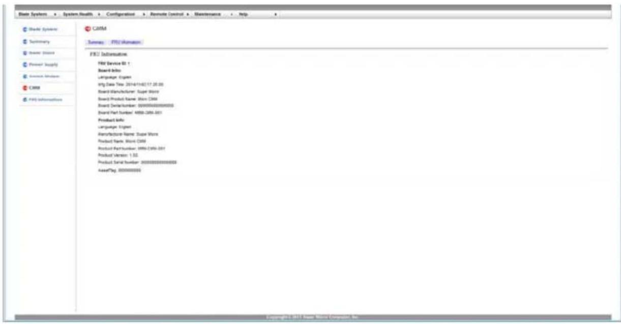
Click on CMM to reveal the CMM STATUS SUMMARY page (Figure 2-18). The CMM option in the BLADE SYSTEM submenu allows you to check the status the CMM module in the system you are accessing. Operating status, temperature, firmware information and IP address information are all shown in this summary page. Additionally, you can view CMM FRU information on the CMM STATUS FRU INFORMATION page (Figure 2-19).
The commands you may give on this page, as described below in Table 2-13.
Figure 2-18. CMM Status Summary Page

Table 2-13. CMM Status – Summary Page Controls
| Item Name Description | ||
| 1 CMM | Name Field | Select a name for Master CMM in this field and press the Apply button to apply the name to it. |
| 2 | Sensor TypeCategory Drop-downList Box | Use this list to select the type of sensors you wish to view. Options include All Sensors, Temperature Sensors or Voltage Sensors. |
| 3 Refresh Button Press this button to refresh the page. | ||
| 4 | Show ThresholdsButton | Pressing this button shows the thresholds for your system. |
NOTE: By default, when the enclosure power turns, the CMM on slot 1 will be the master and the CMM on slot 2 will be the slave. When the master CMM becomes “failed”, the slave CMM will take over. When the failed CMM on slot 1 is replaced, the master CMM will not swap back to slot 1. You may wait until the CMM on slot 2 is “failed” or power cycle whole the enclosure to return to slot 1 resuming to be the master CMM.
NOTE: The "Failover" feature for two CMMs as "master" and "slave", with the CMM redundant feature, is not supported on either the MBE-628L-816 or MBE-628L-416 enclosures.
Figure 2-19. CMM Status – FRU Information Page
2-6 FRU Information
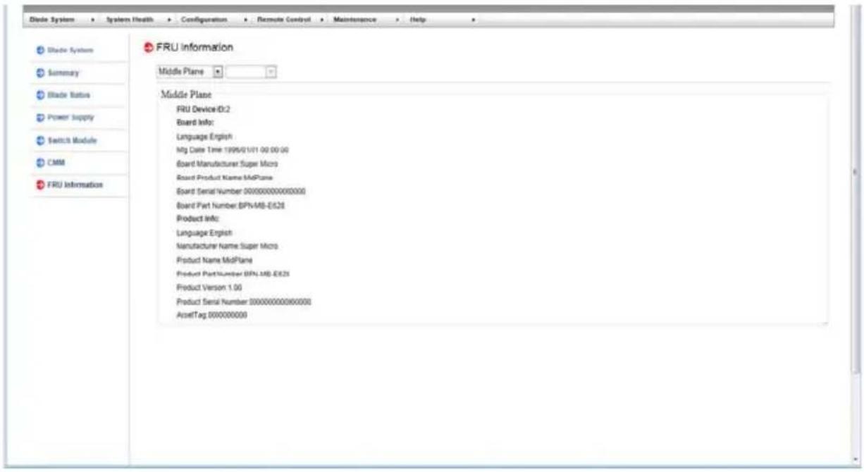
Clicking on the FRU INFORMATION link brings up the FRU INFORMATION page (Figure 2-20) with static FRU information. Use the drop-down list box on the page to select the type of information you wish to view.
Figure 2-20. Blade System – Middle Plane FRU Information Page
Chapter 3 System Health
The SYSTEM HEALTH menu allows you to access and configure logs and alert settings in your system. Clicking the SYSTEM HEALTH icon allows you to access the following pages through its sub-menus:
- Sensor Readings Page
- System Event Log Page
• Power/Temperature Record Page
3-1 Sensor Readings Page
The SENSOR READING page (Figure 3-1) displays system sensor information, including readings and status. You can toggle viewing the thresholds for the sensors by pressing the SHOW THRESHOLDS button below.
Figure 3-1. Sensor Readings Page

Table 3-1. Sensor Readings Page Controls
| Item Name Description | ||
| 1 | Module Selection Drop-down List Box | Select from here the module type whose sensors you wish to view. Options include: CMM, Blade, Switch or Power Supply. |
| 2 | Module Number Selection Drop-down List Box | Select the specific module of the type you selected in the MODULE SELECTION list whose sensors you wish to view. |
| 3 | Sensor Selection Drop-down List Box | Select in this drop-down list box the type of sensor you wish to view from the previous selected module. Options include All Sensors, Temperature Sensors or Voltage Sensors,When you have made all your selections, press the APPLY button to view the sensors. |
| 4 Refresh Button Press this button to refresh the page. | ||
| 5 | Show Thresholds Button | Pressing this button shows the thresholds for your system. |
3-2 System Event Log Page
The SYSTEM EVENT LOG option in the SYSTEM HEALTH submenu allows you to view and clear the contents of the system event log for a remote system. The SYSTEM EVENT LOG page that appears (Figure 3-2) and its controls (Table 3-2) are shown below.
Figure 3-2. System Event Log Page
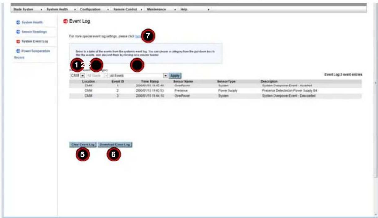
Table 3-2. System Event Log Page Controls
| Item Name Description | ||
| 1 | Module Selection Drop-down List Box | Select from here the module type whose event you wish to view. Options include: CMM or Blade. |
| 2 | Module Number Selection Drop-down List Box | Select the specific module of the type you selected in the MODULE SELECTION list whose event you wish to view. |
| 3 | Event Type Selection Drop-down List Box | Select the specific event type whose event you wish to view. Options include All Events, Sensor Specific Events, BIOS Specific Events or System Management Software Events. |
| 4 Apply | Button | When you have selected your options from all the above drop-down list boxes, press the APPLY button to apply your changes. |
| 5 | Clear Event Log Button | Press this button to clear the event log of all entries. |
| 6 | Download Event Log Button | Press this button to download the event log. |
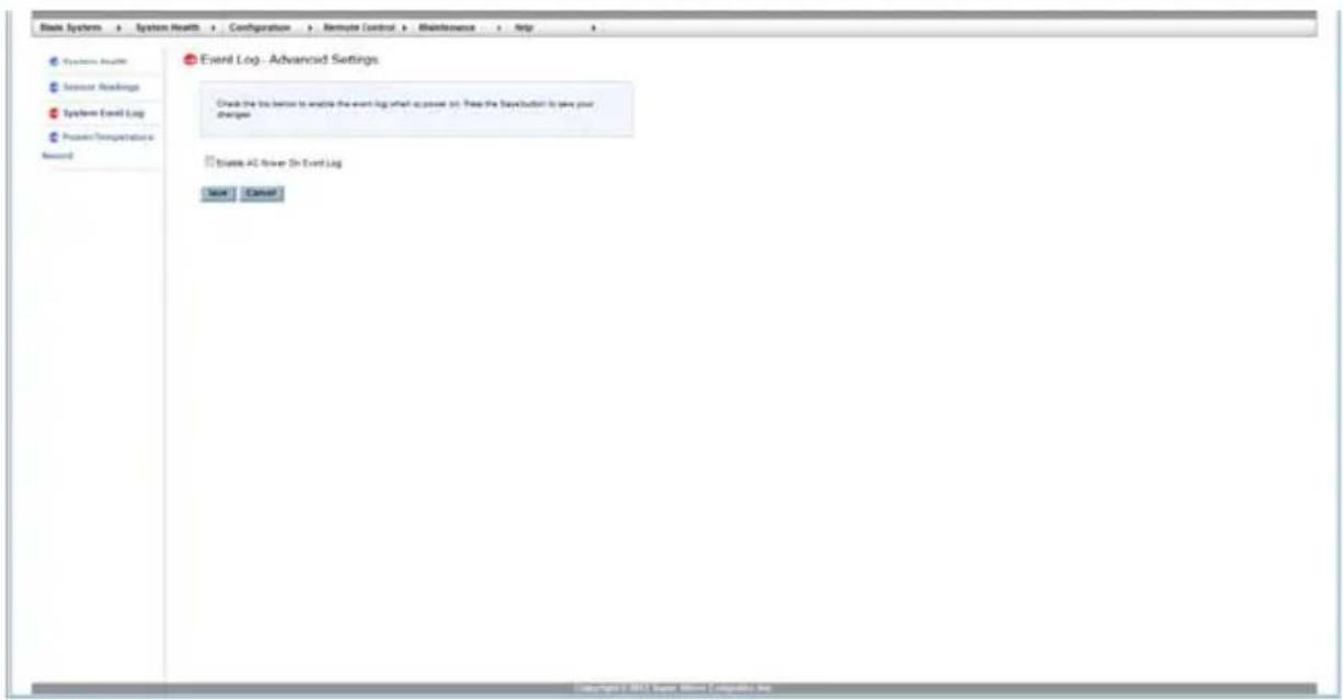
| 7 | Event Log Advanced Settings Link | Press this link to go the Event Log Advanced Settings page (Figure 3-3). This page has a check box to ENABLE THE AC POWER EVENT LOG and buttons to SAVE or CANCEL this configuration. |
Figure 3-3. Event Log – Advanced Settings Page
3-3 Power/Temperature Record Page
The POWER/TEMPERATURE RECORD option in the SYSTEM HEALTH submenu allows you to view and download power and temperature records of the system. The POWER/TEMPERATURE RECORD page that appears (Figure 3-2) and its controls (Table 3-2) are shown below.
Figure 3-4. System Event Log Page
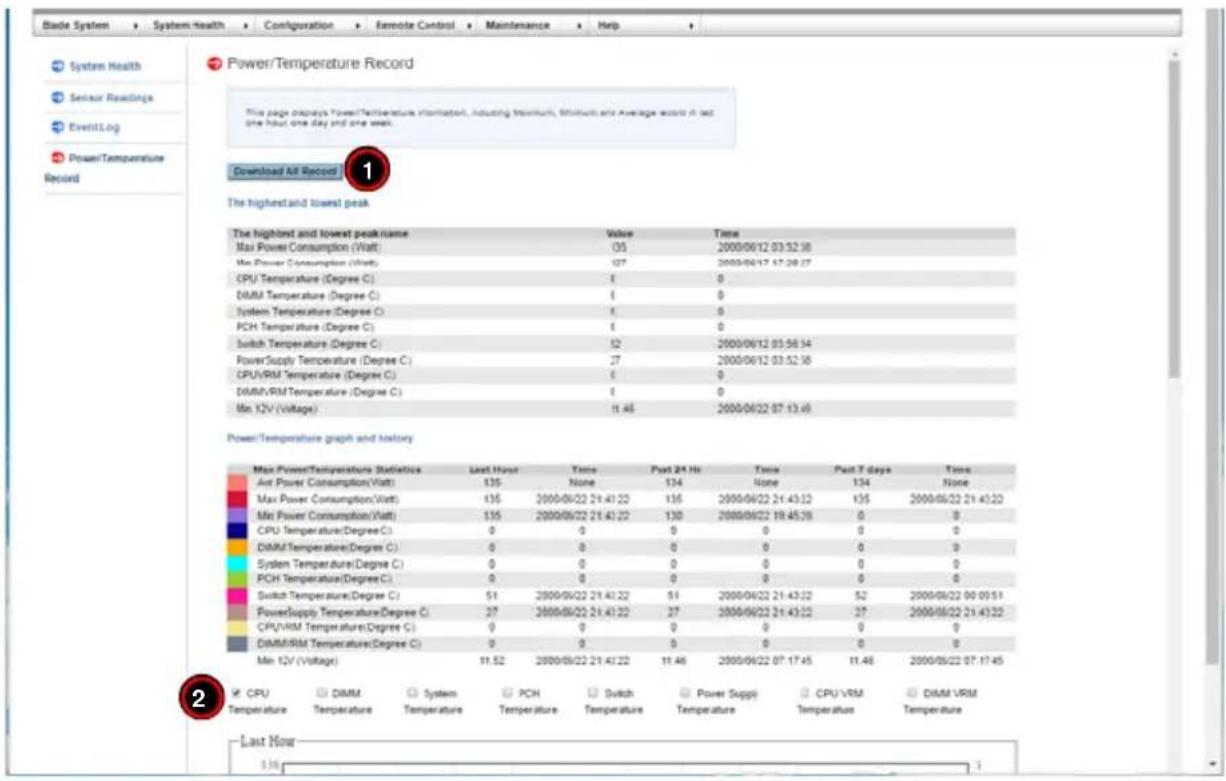
Table 3-3. System Event Log Page Controls
| Item Name Description | ||
| 1 | Download All Record Button | Press this button to download records for all the check boxes above you have selected. |
| 2 | Record Selection Check Boxes | Check the boxes here in order to select the records you wish to download and display on this page. You may select one or all for viewing. |
Notes
Chapter 4 Configuration
The USER MANAGEMENT menu allows you to configure users for your system. Clicking the USER MANAGEMENT icon allows you to access the following pages through its sub-menus:
- A l e r t s P a g e
- Date and Time Page
• L D A P P a g e
• Active Directory Page - RADIUS Page
• CMM Network Page - Blade IPMI Network Page
- Dynamic DNS Page
- SMTP Page
• S N M P P a g e - SSL Certification Page
- Users Page
- Port Page
- IP Access Control Page
- Web Session Page
- SMC RAKP Page
• Auto Update Redundant CMM Page
4-1 Alerts Page
Click on ALERTS to reveal the ALERTS page (Figure 4-1). Use this page to set up alerts for your system. The commands you may give on this page, are described below in Table 4-1.
Figure 4-1. Blade Status Page

To setup an alert or to modify an alert setting, do the following.
- Select an alert entry from the list presented on the page.
- Click M ODIFY to configure or modify the settings of an alert.
- Click SEND TEST ALERT to check if the alerts have been set and sent out correctly.
- Click DELETE if you need to delete an alert.
Table 4-1. Blade Status Page Controls
| Item | Control Name Description | |
| 1 | A l e | This table shows the currently active alerts, their number, their alert level and their destination address. Select from this list in order to modify an alert. |
| 2 | Modify Button | Press this button after selecting an alert from the table brings up the MODIFY ALERT page (Figure 4-2), which you use to modify an alert. In this new page select the Event Severity, Destination IP, Email Address, Subject and Message from the drop-down lists provided and press the SAVE button. If yo wish to cancel the alert, press the CANCEL button. |
| 3 | Send Test Alert Button | Press this button to send a test alert to its specified destination after you have modified the alert. |
| 4 | Delete Button | Press this button to delete an alert from the list. |
Figure 4-2. Modify Alert Page

4-2 Date and Time Page
Click on DATE & TIME to reveal the DATE & TIME page (Figure 4-3). Use this page to set up date and time information for your system. The commands you may give on this page, are described below in Table 4-2.
Figure 4-3. Date and Time Page
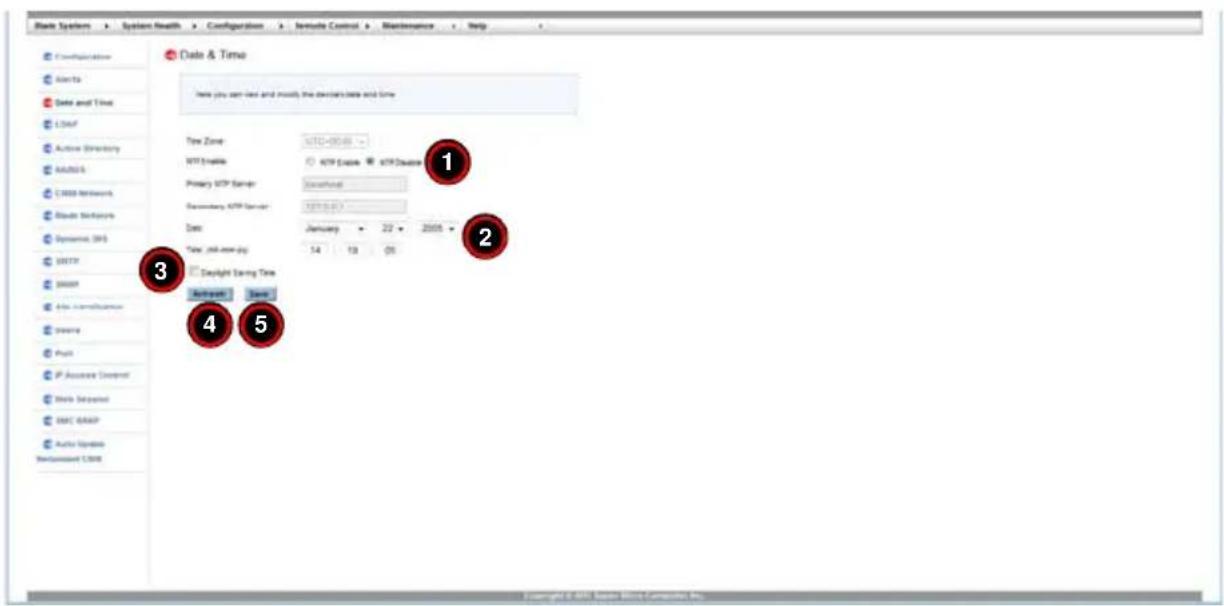
Table 4-2. Date and Time Page Controls
| Item | Control Name Description | |
| 1 | Time Update Mode Option Buttons | Using these option buttons, you may select either NTP Enable or NPT Disable mode for time updates to the system. Each mode, when selected, activates or deactivates fields or drop-down list boxes for specifying date and time information or the primary or secondary NTP server. |
| 2 | Time Specification Drop-down List Box | Use these drop-down list boxes to specify the date and time information. These controls change depending upon which options you choose in the NTP or NPT option buttons. |
| 3 | Daylight Savings Time Check Box | Click this check box if you wish to use daylight savings time for your time settings. |
| 4 | Refresh Button Press this button to refresh the page. | |
| 5 | Save Button | Pressing the SAVE button saves the configuration for the selected node or blade module. |
4-3 LDAP Page
Click on LDAP to reveal the LDAP page (Figure 4-4). This page allows you to configure the Light-Weight Directory Access Protocol (LDAP) settings. Check the box below to enable LDAP authentication and enter the required information to access the LDAP server. Press the Save button to save your changes. The commands you may give on this page, are described below in Table 4-3.
Figure 4-4. LDAP Page
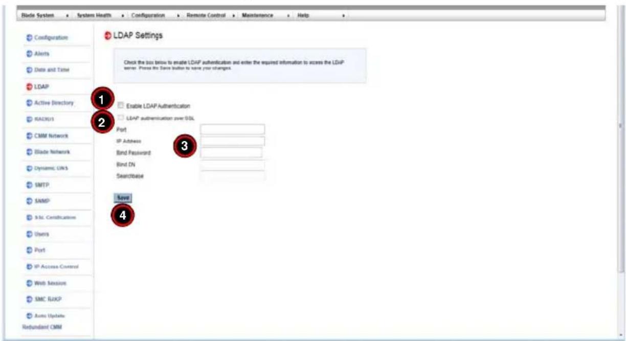
Table 4-3. LDAP Page Controls
| Item | Control Name Description | |
| 1 | Enable LDAP Authentication | Use this check box to enable the controls below to configure LDAP for your system. |
| 2 | LDAP Authentication over SSL | Check this box to allow LDAP Authentication over SSL in your system. |
| 3 | Configuration fields | Enter Port, IP Address, Bind Password, Bind DN and Searchbase in the fields in this section to configure LDAP for your system. |
| 4 | Save Button | Once you are done configuring LDAP, press this button to save this information to your system. |
4-4 Active Directory Page
Click on ACTIVE DIRECTORY to reveal the ACTIVE DIRECTORY page (Figure 4-5). This page displays a list of role groups and their Group IDs, Group Names, Domains and Network Privilege settings. If you would like to delete or modify a role group, select the name in the list and press DELETE ROLE GROUP or MODIFY ROLE GROUP. To add a new role group, select an unconfigured slot from the table and press ADD ROLE GROUP. The commands you may give on this page, are described below in Table 4-4.
Figure 4-5. Active Directory Page
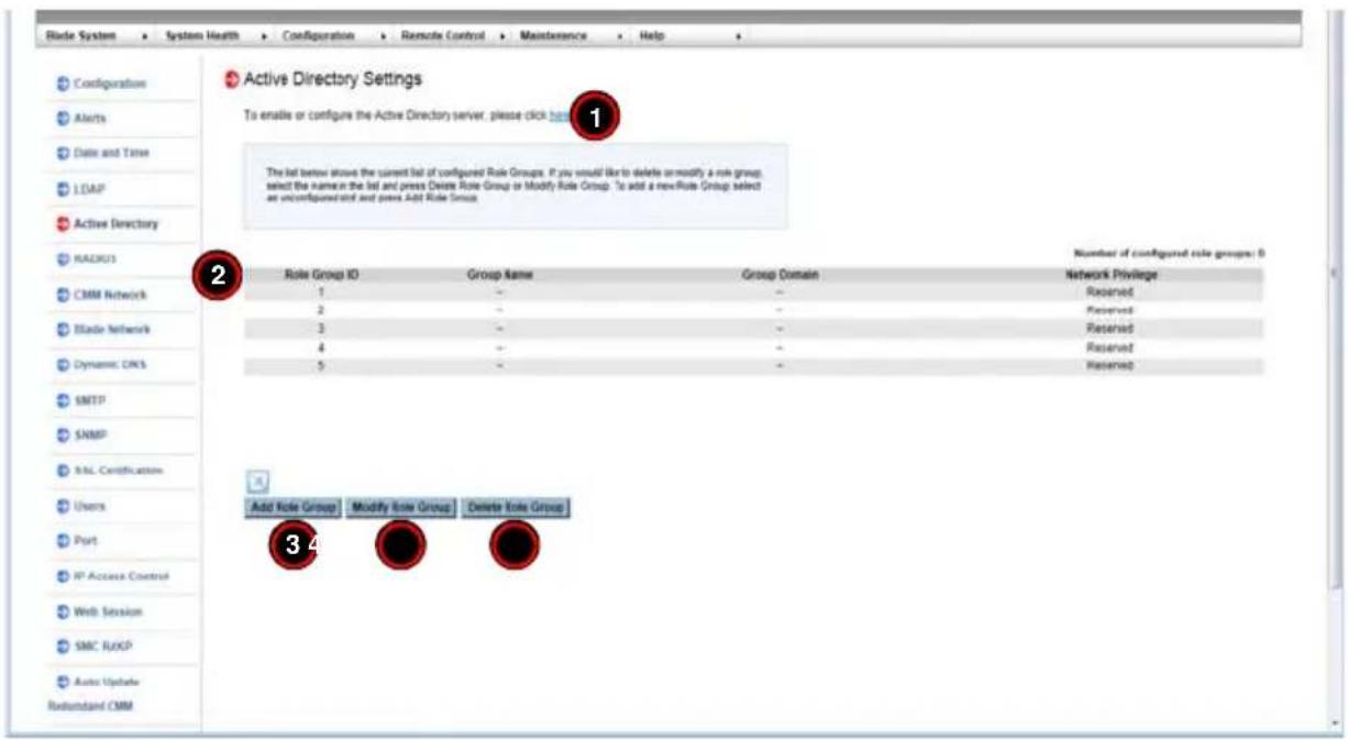
Table 4-4. Active Directory Page Controls
| Item | Control Name Description | |
| 1 | Active Directory Server Link | Click on this link to go to the Active Directory - Advanced Settings page (Figure 4-8). |
| 2 | Role Group List | Select a role group from this list to modify or delete a role group. Press the ADD ROLE GROUP button to add a role group or select a role group and press the MODIFY ROLE GROUP button to modify one of them in the list. |
| 3 | Add Role Group Button | Press this button to add a role group to the list of role groups in the table above. This will bring up the ADD ROLE GROUP page (Figure 4-6) where you can enter information and save it as a new role group in the ROLE GROUP list. |
| 4 | Modify Role Group Button | After selecting a role group from the list above, press this button to modify a role group. Pressing this button brings up the MODIFY ROLE GROUP page (Figure 4-7) where you can modify information in the group and save it in the ROLE GROUP list. |
| 5 | Delete Role Group Button | If you wish to delete a role group, select it from the list and press this button. |
Figure 4-6. Add Role Group Page

Figure 4-7. Modify Role Group Page

Active Directory - Advanced Settings Page
Figure 4-8. Active Directory - Advanced Settings Page

Click on ACTIVE DIRECTORY SERVER link to reveal the ACTIVE DIRECTORY - ADVANCED SETTINGS page (Figure 4-8). This page displays two check boxes that allow you to ENABLE ACTIVE DIRECTORY AUTHENTICATION and ACTIVE DIRECTORY AUTHENTICATION OVER SSL. When checked, the table below opens allowing you to specify PORT, USER DOMAIN NAME, TIME OUT and DOMAIN CONTROLLER SERVER ADDRESSES. Pressing the SAVE Button allows you to save this configuration, while pressing CANCEL cancels the configuration.
4-5 RADIUS Page
Click on RADIUS to reveal the RADIUS page (Figure 4-9). You can use this page to enable RADIUS and enter the required information to access the RADIUS server. The commands you may give on this page, are described below in Table 4-5.
Figure 4-9. RADIUS Page
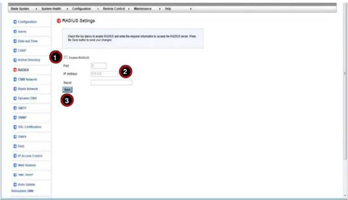
Table 4-5. RADIUS Page Controls
| Item | Control Name Description | |
| 1 | Enable RADIUS Check Box | Check this box to enable RADIUS. |
| 2 | RADIUS Information Fields | Fill out these fields to configure RADIUS. |
| 3 Save | Button Once you are done | configuring RADIUS, press this button to save. |
4-6 CMM Network Page
Click on CMM NETWORK to reveal the CMM NETWORK page (Figure 4-10). You can view and modify the network settings on this page and select whether to obtain an IP address automatically or manually configure one. The commands you may give on this page, are described below in Table 4-6.
Figure 4-10. CMM NetworkPage
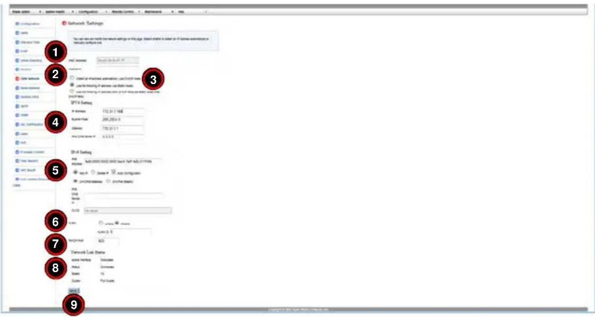
Table 4-6. CMM Network Page Controls
| Item | Control Name | Description |
| 1 MAC | Address | When you specify the IP Address manually, use this field to specify your MAC Address. If you have chosen to have your IP address automatically determined, then this control is greyed-out and cannot be modified. |
| 2 Hostname | Use this field to specify your Hostname. | |
| 3 | Automatic or Manual IP Address Controls | Use these two option buttons to either OBTAIN AN IP ADDRESS AUTOMATICALLY (USING DHCP MODE) or USE THE FOLLOWING IP ADDRESSES (USE STATIC MODE) to either automatically or manually specify an IP address for the network. |
| 4 | IPv4 Setting Controls | Use these controls specify your IP ADDRESS, SUBNET MASK, GATEWAY address and DNS SERVER IP. If you have chosen to have your IP address automatically determined, then these fields are greyed-out and cannot be modified except for DNS SERVER IP address. |
| 5 | IPv6 Setting Controls | Use these controls to do the following: set IPv6 ADDRESS, ADD IP, DELETE IP, use AUTO CONFIGURATION, select either DHCPv6 STATELESS or DHCPv6 STATEFUL modes, specify your DNS SERVER IP or specify your DUID. |
| 6 | VLAN Controls | Use these controls to ENABLE or DISABLE VLAN or specify the VLAN ID. |
| 7 RMCP | Port Use this field to specify your RMCP port number. | |
| 8 | Network Link Status | This section shows your network link status for Active Interface, Status, Speed and Duplex. |
| 9 Save | Button | Once you are done configuring your network settings, press this button to save your configurations. |
4-7 Blade IPMI Network Page
Click on BLADE IPMI NETWORK to reveal the BLADE IPMI NETWORK page (Figure 4-11). This page allows you to modify all blade and their networks by one click on this page. If you use Static mode, the base IP address will set to the first Node of a blade's A1 and increase base IP address in the order for the following nodes. The commands you may give on this page, are described below in Table 4-7.
Figure 4-11. Blade IPMI Network Page

Table 4-7. Blade IPMI Network Page Controls
| Item | Control Name | Description |
| 1 | Automatic or Manual IP Address Controls | Use these two option buttons to either OBTAIN AN IP ADDRESS AUTOMATICALLY (USING DHCP MODE) or USE THE FOLLOWING IP ADDRESSES (USE STATIC MODE) to either automatically or manually specify an IP address for the network. |
| 2 | IPv4 Setting Controls | Use these controls specify your BASE IP ADDRESS, SUBNET MASK and GATEWAY address. If you have chosen to have your IP address automatically determined, then these fields are greyed-out and cannot be modified. |
| 3 | Apply Above Settings to All Blades and Effective All the Time Check Box | If you check this box, then all IPv4 settings in the above section for ALL blade modules will use these settings ALL THE TIME and auto reset to these settings when the blades start up. |
| 4 Save | Button | Once you are done configuring your Blade Network settings, press this button to save your configurations. |
4-8 Dynamic DNS Page
Click on DYNAMIC DNS to reveal the DYNAMIC DNS page (Figure 4-12). Use this page to configure dynamic update properties. The commands you may give on this page, are described below in Table 4-8.
Figure 4-12. Dynamic DNS Page
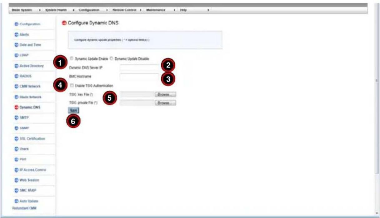
Table 4-8. Dynamic DNS Page Controls
| Item | Control Name Description | |
| 1 | Dynamic Update Enable/Disable Check Boxes | Use these check boxes to enable or disable the Dynamic DNS feature for your system. |
| 2 | Dyanmic DNS Server IP Field | Enter the Dynamic DNS Server IP address in this field. |
| 3 | BMC Hostname Field Enter the BMC Hostname in this field. | |
| 4 | Enable TSG Authentication Check Box | If you want to enable TSG Authentication, then check this box. |
| 5 | TSG .key File/TSG .private File fields | Optionally, you may use these controls to browse and specify the locations for TSG .key or TSG .private files. |
| 6 | Save Button | Once you are done configuring your Dynamic DNS settings, press this button to save your configurations. |
4-9 SMTP Page
Click on SMTP to reveal the SMTP page (Figure 4-13). Use this page to enter the IP Address for the SMTP Mail server and some of its configurations. The commands you may give on this page, as described below in Table 4-9.
Figure 4-13. SMTP Page

Table 4-9. SMTP Page Controls
| Item | Control Name Description | |
| 1 | SMTP SSL Auth Check Box | Checking this check box allows you to require SMTP SSL authorization. |
| 2 | SMTP Server Field | This field is used to specify the SMTP Server address. |
| 3 | SMTP Port Number Field | This field is used to specify the SMTP Port Number. |
| 4 | SMTP User Name Field | This field is used to specify the SMTP User Name. |
| 5 | SMTP Password Field | This field is used to specify the SMTP Password. |
| 6 | Sender's Address Field | This field is used to specify the Sender's Address. |
| 7 Save | Button | Once you are done configuring your Dynamic DNS settings, press this button to save your configurations. |
4-10 SNMP Page
Click on SNMP to reveal the SNMP page (Figure 4-14). Use this page to enter the IP Address for the SMTP Mail server and some of its configurations. The commands you may give on this page, as described below in Table 4-10.
Figure 4-14. SNMP Page

Table 4-10. SNMP Page Controls
| Item | Control Name Description | |
| 1 SNMP | Settings Fields | Use these fields to configure SNMP system information, communities and users for SNMP v1/v2/v3. The information in these fields is for each record. |
| 2 Save | Button | After configuring the above fields, press the SAVE button to save this information to a record. |
| 3 Add | User Button | Press this button to open the ADD NEW SNMPv3 USER screen (Figure 4-15) to add a new SNMPv3 user to the SNMPv3 USER LIST above. Simply enter information in the fields and select from the drop-down list boxes the information for the new user and either press the ADD button to add a user or the CANCEL button to cancel the operation. |
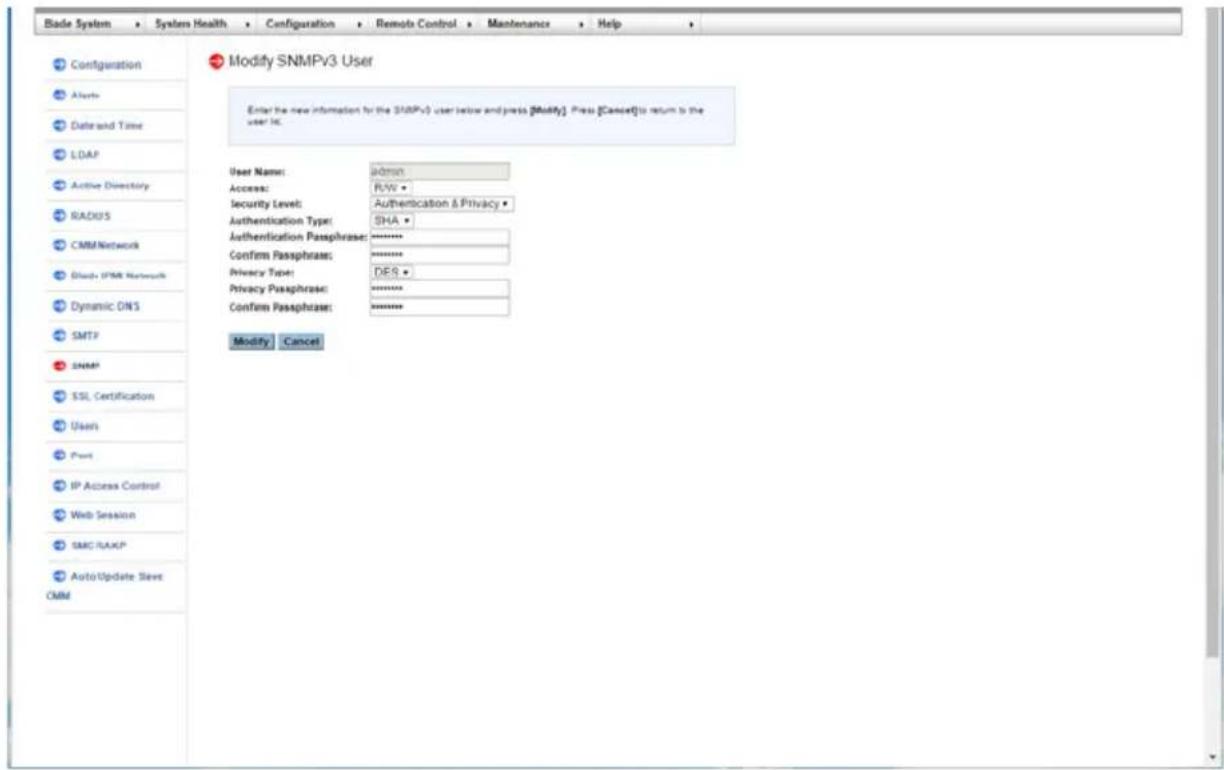
| 4 Modify | User Button | Pressing this button modifies a selected user in the above SNMPv3 USER LIST by opening the MODIFY SNMPv3 USER screen (Figure 4-16). Simply change the information in the fields or drop-down list boxes for the user and either press the MODIFY button to modify a user or the CANCEL button to cancel the operation. |
| 5 Delete | User Button | Pressing this button deletes a selected user from the above SNMPv3 USER LIST. |
Figure 4-15. Add New SNMPv3 User Screen

Figure 4-16. Modify SNMPv3 User Screen
4-11 SSL Certification Page
Click on SSL CERTIFICATION to reveal the SSL CERTIFICATION page (Figure 4-17). Use this page to specify the dates for the default certificate and private key and upload an SSL certificate. The commands you may give on this page, as described below in Table 4-11.
Figure 4-17. SSL Certification Page

Table 4-11. SSL Certification Page Controls
| Item | Control Name Description | |
| 1 | New SSL Certificate Choose File Button | Press this button to select a SSL Certificate file to use from your system. |
| 2 | New Private Key Choose File Button | Press this button to select a New Private Key to use from your system. |
| 3 | Upload Button | Press this button to upload the selected files for the SSL Certificate and the New Private Key to your system. |
4-12 Users Page
The USERS page (Figure 4-12) is where you specify and manage groups and users, which helps you manage the remote systems you are managing. Its controls are shown in Table 4-12.
Figure 4-18. Users Page
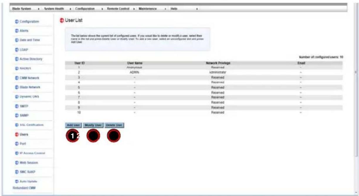
Table 4-12. Users Page Controls
| Item | Control Name Description | Option |
| 1 Add | User Button | Selecting an unconfigured slot and pressing this button allows you to specify a new user for the User List on the page. |
| 2 Modify | User Button | Selecting a user and pressing this button allows you to modify a user from the User List on the page. |
| 3 Delete | User Button | Selecting a user and pressing this button allows you to delete a user from the User List on the page. |
4-13 Port Page
Click on PORT to reveal the PORT SETTING page (Figure 4-19). Use this page to configure a port number for your system. The commands you may give on this page, as described below in Table 4-13.
Figure 4-19. Port Setting Page
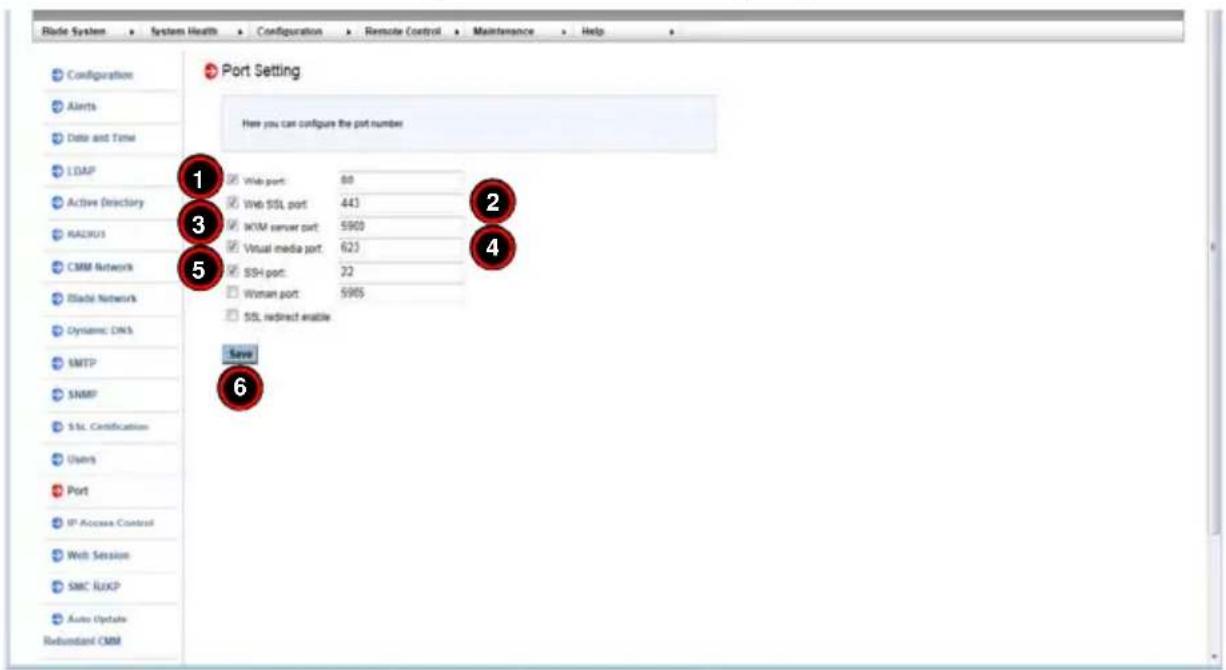
Table 4-13. Port Setting Page Controls
| Item | Control Name Description | |
| 1 | Web Port Number Field | User this field to enter the Web Port number. |
| 2 | Web SSL Port Number Field | User this field to enter the Web SLL Port number. |
| 3 | KVM Server Port Number | User this field to enter the KVM Server Port number. |
| 4 | Virtual Media Port Number | User this field to enter the Virtual Media Port number. |
| 5 | SSL Redirect Enable Check Box | Check this box to enable SSL redirect for your system. |
| 6 Save | Button | Once you are done configuring your Port Number settings, press this button to save your configuration. |
4-14 IP Access Control Page
Click on IP ACCESS CONTROL to reveal the IP ACCESS CONTROL page (Figure 4-20). Use this page to add, modify or delete an IP access rule and to enable IP Access Control to the Rule List on this page. The commands you may give on this page, as described below in Table 4-14.
Figure 4-20. IP Access Control Page
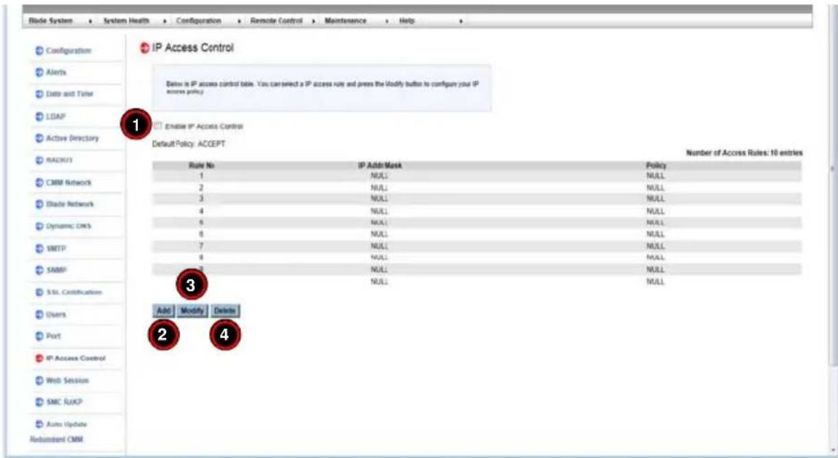
Table 4-14. IP Access Control Page Controls
| Item | Control Name Description | |
| 1 | Enable IP Access Control Check Box | Check this box to enable Access Control for your system. |
| 2 Add | Button | Selecting an unconfigured slot and pressing this button allows you to specify a new rule for the Access Control Rule list on the page. |
| 3 Modify | Button | Selecting a user and pressing this button allows you to modify a rule from the Access Control Rule list on the page. |
| 4 Delete | Button | Selecting a user and pressing this button allows you to delete a rule from Access Control Rule list on the page. |
4-15 Web Session Page
Click on WEB SESSION to reveal the WEB SESSION page (Figure 4-21). Use this page to web session parameters for your system. The commands you may give on this page, as described below in Table 4-15.
Figure 4-21. Web Session Page

Table 4-15. Web Session Page Controls
| Item | Control Name Description | |
| 1 | Session Timeout Value | Use this number field to enter the amount of minutes before a timeout occurs when using a web session. Enter 1-30 for the amount of minutes or 0 for no timeout. |
| 2 Save | Button | Once you are done configuring your Web Session settings, press this button to save your configuration. |
4-16 SMC RAKP Page
Click on SMC RAKP to reveal the SMC RAKP page (Figure 4-22). Use this page to specify SMC RAKP parameters for your system. The commands you may give on this page, as described below in Table 4-16.
Figure 4-22. SMC RAKP Page
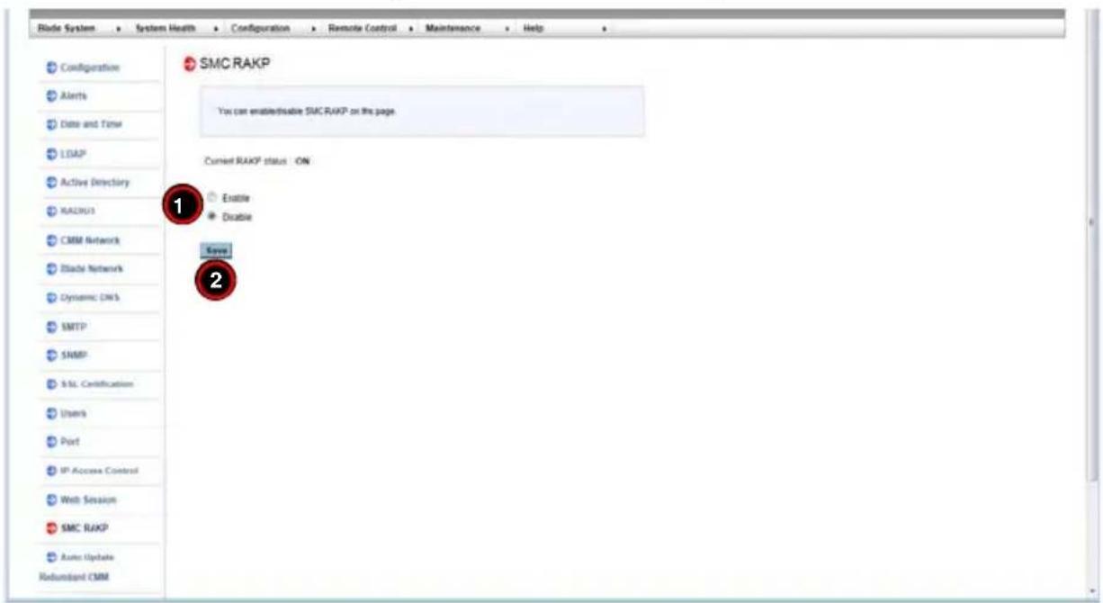
Table 4-16. SMC RAKP Page Controls
| Item | Control Name Description | |
| 1 | RAKP Enable/Disable Option Buttons | Use these option buttons to Enable or Disable SMC RAKP in your system. |
| 2 Save | Button | Once you are done configuring your settings, press this button to save your configuration. |
4-17 Auto Update Redundant CMM Page
Click on AUTO UPDATE REDUNDANT CMM to reveal the AUTO UPDATE REDUNDANT CMM page (Figure 4-23). Use this page to specify automatically updating redundant CMM firmware for your system. The commands you may give on this page, as described below in Table 4-17.
Figure 4-23. Auto Update Redundant CMM Page

Table 4-17. Auto Update Redundant CMM Page Controls
| Item | Control Name Description | |
| 1 | Enable Firmware: Auto Redundant CMM Check Box | Click on this check box to Enable the firmware auto redundant CMM function in your system. |
| 2 Save | Button | Once you are done configuring your settings, press this button to save your configuration. |
Chapter 5 Remote Console
This chapter covers the use of the Remote Console in the Web-based Management Utility software.
- Console Redirection Page
- Launch SOL
5-1 Console Redirection Page
Click on CONSOLE REDIRECTION to reveal the CONSOLE REDIRECTION page (Figure 5-1). Use this page to launch the REDIRECTION CONSOLE window and mange the blade/node server remotely. The commands you may give on this page, are described below in Table 5-1.
Figure 5-1. Console Redirection Page
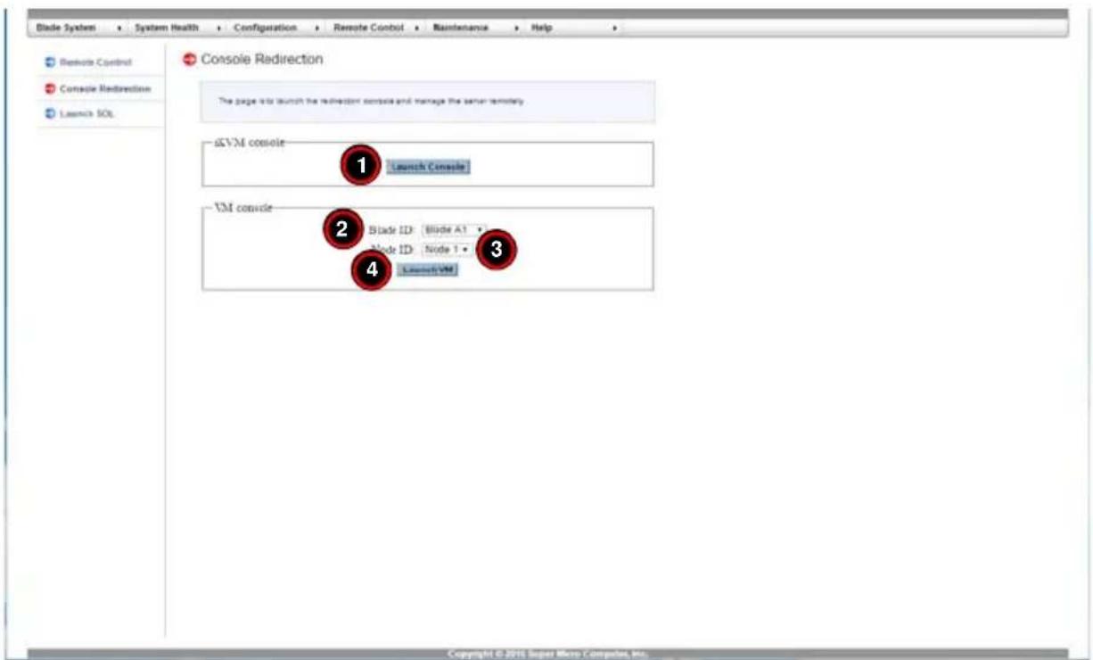
Table 5-1. Console Redirection Page Controls
| Item | Control Name Description | |
| 1 | Launch Console Button | Press this button to launch a REMOTE CONSOLE window for the selected blade module and node to view. |
| 2 | Blade ID Selection List | Use this selection list to select the blade server. |
| 3 | Node ID Selection List | Use this list to view the node you wish to view in the console windows. |
| 4 | Launch VM Button Use this button to launch VM. | |
5-2 Launch SOL
Click on LAUNCH SOL to reveal the SOL CONSOLE page (Figure 5-2). Use this page to launch the SOL CONSOLE window and mange the blade server/node remotely. The commands you may give on this page, are described below in Table 5-2.
Figure 5-2. SOL Console Page

Table 5-2. SOL Console Page Controls
| Item | Control Name Description | |
| 1 | Blade ID Selection List | Use this selection list to select the blade server. |
| 2 | Node ID Selection List | Use this list to view the node you wish to view in the console windows. |
| 3 | Launch SOL Button | Press this button to launch a SOL CONSOLE window for the selected blade module and node to view. |
Chapter 6 Maintenance
Use the MAINTENANCE menu for maintenance configurations on your system. Clicking the MAINTENANCE icon allows you to access the following pages through its sub-menus:
• CMM Firmware Update Page
• CMM Unit Reset Page
- Factory Default Page
• CMM Configuration Page
- System Event Log Page
- UID Control Page
6-1 CMM Firmware Update Page
Clicking the CMM UPDATE FIRMWARE link in the MAINTENANCE submenu brings up the CMM FIRMWARE UPDATE page (Figure 6-1). Pressing the UPDATE MASTER CMM to update the Master CMM firmware. Press the UPDATE SLAVE CMM button to update the Slave CMM firmware and press the SYNC SLAVE CMM to sync the Slave CMM to the master CMM.
Figure 6-1. Update Firmware Page
![Blade System Maintenance CMM Firmware Update CMM Unit Reset Factory Default CMM Configuration System Event Log USD Control CMM Firmware Update This page allows firmware update by pressing [Enter Update Mode] to put the device in a special mode. Please note that once you enter update mode the device…](/content/2026/05/1074119/images/0cf20de131aff442c7bbea67ea7458182c734a296d3381b4b15ab4a04308f946.jpg)
NOTE: Once you put this device into Update Mode, the device will reset if the update process is canceled. This process is not reversible once the firmware is updated, so proceed with caution. It might take a few minutes to complete this procedure.
6-2 CMM Unit Reset Page
Clicking the CMM UNIT RESET link in the MAINTENANCE submenu brings up the UNIT RESET page (Figure 6-2). Pressing the RESET button on this page reboots the IPMI device.
Figure 6-2. Unit Reset Page
![Blade System Maintenance CMM Features Update CMM Unit Reset Factory Default CMM Configuration System Event Log UNIT Control CMM Unit Reset This page is to reboot the CMM by clicking on the [Reset] button. Reset Copyright © 2015 Super Micro Computer, Inc.](/content/2026/05/1074119/images/c55e2eb1a0ebb8d6106ecd885511e8c4f22dfbc5d08a716fa1c971b6b85bd7e9.jpg)
6-3 Factory Default Page
Clicking the FACTORY DEFAULT link in the MAINTENANCE submenu brings up the FACTORY DEFAULT page (Figure 6-3). Pressing the RESTORE button on this page restores the factory default settings back to the IPMI device.
Figure 6-3. Factory Default Page

6-4 CMM Configuration Page
Clicking the CMM CONFIGURATION link in the MAINTENANCE submenu brings up the CM CONFIGURATION page (Figure 6-4). This page allows you to save the current IPMI configuration and restore it. Press the SAVE button to save the current configuration. If you wish to restore a previous configuration, then press the BROWSE button to locate and select the previously saved configuration file and then press the RELOAD button to restore it.
NOTE: It is recommended that you save your configuration so that you can restore it in the future in case a new configuration is not to your liking.
Figure 6-4. CMM Configuration Page

6-5 System Event Log Page
Clicking the SYSTEM EVENT LOG link in the MAINTENANCE submenu brings up the LIST OF SYSTEM EVENT LOG page (Figure 6-5). This page contains information on events that are recorded by the SIMCM in the order of Number, Date/Time, IP Address and Descriptions. Check the ENABLE SYSTEM EVENT LOG check box to enable this feature and press the CLEAR button to clear the log list.
Figure 6-5. List of System Event Log Page

6-6 UID Control Page
Clicking the UID CONTROL link in the MAINTENANCE submenu brings up the UID CONTROL page (Figure 6-6). On this click on the UID ON/OFF list button to turn the devices UID or click it off to turn off the UID..
Figure 6-6. List of System Event Log Page

Appendix A Checking the MAC Address
Use the following procedure to check the MicroBlade's MAC address and other information through the command line interface. You can enter the CMM IP address through Putty SSH to get this information.
Checking the MAC Address through the CMM Command Line Interface
- Login as an ADMIN using the command ssh ADMIN@CMMIP.
- Connect to the command line interface using the command connect cli.
- Get the MAC address and other information using the command list macaddress.
See Figure A-1 for an example of the above procedure.
Figure A-1. Checking the MAC Address using the Command Line Interface

Notes
Disclaimer
The products sold by Supermicro are not intended for and will not be used in life support systems, medical equipment, nuclear facilities or systems, aircraft, aircraft devices, aircraft/emergency communication devices or other critical systems whose failure to perform be reasonably expected to result in significant injury or loss of life or catastrophic property damage. Accordingly, Supermicro disclaims any and all liability, and should buyer use or sell such products for use in such ultra-hazardous applications, it does so entirely at its own risk. Furthermore, buyer agrees to fully indemnify, defend and hold Supermicro harmless for and against any and all claims, demands, actions, litigation, and proceedings of any kind arising out of or related to such ultra-hazardous use or sale.


- WEB-BASED MANAGEMENT UTILITY
- USER'S MANUAL
- PREFACE
- ABOUT THIS MANUAL
- MANUAL ORGANIZATION
- CHAPTER 1: INTRODUCTION
- CHAPTER 2: BLADE SYSTEM
- CHAPTER 3: SYSTEM HEALTH
- CHAPTER 4: CONFIGURATION
- CHAPTER 5: REMOTE CONSOLE
- CHAPTER 6: MAINTENANCE
- CONTACTING SUPERMICRO
- HEADQUARTERS
- EUROPE
- ASIA-PACIFIC
- TABLE OF CONTENTS
- CHAPTER 1 INTRODUCTION....1-1
- CHAPTER 2 BLADE SYSTEM ...... 2-1
- CHAPTER 3 SYSTEM HEALTH....3-1
- CHAPTER 4 CONFIGURATION 4-1
- CHAPTER 5 REMOTE CONSOLE....5-1
- CHAPTER 6 MAINTENANCE....6-1
- APPENDIX A CHECKING THE MAC ADDRESS.....A-A
- LIST OF FIGURES
- LIST OF TABLES
- NOTES
- CHAPTER 1 INTRODUCTION
- SUPPORTED BROWSERS
- NETWORK CONNECTION/LOGIN
- RESET
- ADDRESS DEFAULTS
- PAGE ELEMENTS AND CONTROLS
- MAIN MENU BUTTONS
- CHAPTER 2 BLADE SYSTEM
- BLADE SYSTEM SUMMARY PAGE
- BLADE STATUS PAGE
- NODE STATUS PAGE
- NODE STATUS – SUMMARY PANE
- NODE STATUS – SENSOR READING PANE
- NODE STATUS – NETWORK SETTINGS PANE
- NODE STATUS – EVENT LOG PANE
- NODE STATUS – FRU INFORMATION PAGE
- NODE STATUS – DATE & TIME PAGE
- NODE STATUS – POWER/TEMPERATURE RECORD PAGE
- NODE STATUS – NODE PRODUCT KEY PAGE
- NODE STATUS – HARDWARE INFORMATION PAGE
- POWER SUPPLY PAGE
- POWER SUPPLY STATUS PAGE
- POWER SUPPLY STATUS—SUMMARY PANE
- POWER SUPPLY STATUS – FRU INFORMATION PAGE
- SWITCH MODULE PAGE
- SWITCH MODULE STATUS PAGE
- SWITCH MODULE STATUS—SUMMARY PANE
- SWITCH MODULE STATUS – FRU INFORMATION PAGE
- CMM PAGE
- FRU INFORMATION
- CHAPTER 3 SYSTEM HEALTH
- SENSOR READINGS PAGE
- SYSTEM EVENT LOG PAGE
- POWER/TEMPERATURE RECORD PAGE
- CHAPTER 4 CONFIGURATION
- ALERTS PAGE
- DATE AND TIME PAGE
- LDAP PAGE
- ACTIVE DIRECTORY PAGE
- ACTIVE DIRECTORY - ADVANCED SETTINGS PAGE
- RADIUS PAGE
- CMM NETWORK PAGE
- BLADE IPMI NETWORK PAGE
- DYNAMIC DNS PAGE
- SMTP PAGE
- SNMP PAGE
- SSL CERTIFICATION PAGE
- USERS PAGE
- PORT PAGE
- IP ACCESS CONTROL PAGE
- WEB SESSION PAGE
- SMC RAKP PAGE
- AUTO UPDATE REDUNDANT CMM PAGE
- CHAPTER 5 REMOTE CONSOLE
- CONSOLE REDIRECTION PAGE
- LAUNCH SOL
- CHAPTER 6 MAINTENANCE
- CMM FIRMWARE UPDATE PAGE
- CMM UNIT RESET PAGE
- FACTORY DEFAULT PAGE
- CMM CONFIGURATION PAGE
- UID CONTROL PAGE
- APPENDIX A CHECKING THE MAC ADDRESS
- CHECKING THE MAC ADDRESS THROUGH THE CMM COMMAND LINE INTERFACE
- HELP ← 3
- LIST MACADDRESS ← 4
- DISCLAIMER
Brand : Supermicro
Model : MBM-CMM-001
Category : Computer Server