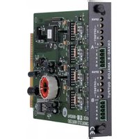
CNXAO-8 - Electronic board Crestron - Free user manual and instructions
Find the device manual for free CNXAO-8 Crestron in PDF.


| Product Type | Audio Output Expander |
| Dimensions | 8.4 in x 5.2 in x 1.7 in (213 mm x 132 mm x 43 mm) |
| Weight | 1.2 lbs (0.54 kg) |
| Power | 24V DC, 0.5A |
| Number of Channels | 8 |
| Audio Output Type | Analog, balanced/unbalanced |
| Volume Control | Per-channel via Cresnet |
| Mute Function | Per-channel mute |
| Signal Routing | Independent channel routing |
| Communication | Cresnet |
| Connectors | 8x 3.5mm terminal block outputs |
| LED Indicators | Power, Cresnet, signal per channel |
| Operating Temperature | 32°F to 104°F (0°C to 40°C) |
| Humidity | 10% to 90% non-condensing |
| Mounting | Rack-mountable (optional bracket) |
| Maintenance | Clean with dry cloth; avoid liquids |
| Safety | Use approved power supply; do not expose to moisture |
| Spare Parts | Power supply, mounting brackets |
| General Information | Part of Crestron CNX series |
Frequently Asked Questions - CNXAO-8 Crestron
User questions about CNXAO-8 Crestron
0 question about this device. Answer the ones you know or ask your own.
Ask a new question about this device
Download the instructions for your Electronic board in PDF format for free! Find your manual CNXAO-8 - Crestron and take your electronic device back in hand. On this page are published all the documents necessary for the use of your device. CNXAO-8 by Crestron.
USER MANUAL CNXAO-8 Crestron
CNX Analog Output Expansion Card
Operations Guide
Contents
CNX Analog Output Expansion Card: CNXAO-8 1
Description....1
Functional Description .... 1
Physical Description....1
Leading Specifications....2
Setup 2
Power Up/Reset Voltage Adjustment....2
Installation....3
Output Voltage Limit Adjustment....3
Programming with SIMPL™ Windows® 5
How the Program Works....5
How to Create the Program....6
Problem Solving 11
Troubleshooting....11
Further Inquiries....12
Return and Warranty Policies....13
Merchandise Returns / Repair Service 13
CRESTRON Limited Warranty....13
CNX Analog Output Expansion Card: CNXAO-8
Description
Functional Description
The CNXAO-8 Analog Output Expansion Card provides eight analog output connections with a maximum voltage span of +/-12 VDC and 80 mA maximum source/sink current. The analog output connections are arranged as two groups of four with a multi-turn span adjustment for each group. Each group has a jumper (X1 and X2) to select whether the outputs power up/reset at 0% or 50%. Furthermore, each output has a multi-turn offset potentiometer (pot) to position span as required.
Physical Description
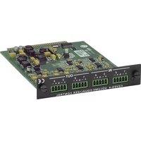
The CNXAO-8, shown below, is a circuit board fastened to an aluminum faceplate. The card is manufactured to easily fit into an unoccupied slot in a Crestron CNX Generation Control System.
CNXAO-8 Faceplate

The faceplate contains two identical 5-position mini-Phoenix type connectors (labeled A and B). There are four analog output pins and one common ground pin per connector. Silk screening is applied to the faceplate; pins are labeled A1 through A4 and B1 through B4. Common ground pins are labeled with a G. All pots are accessible from outside the CNX Generation Control System through holes in the faceplate.
Leading Specifications
The table below provides a summary of leading specifications for the CNXAO-8. Dimensions and weight are rounded to the nearest hundredth unit.
Leading Specifications of the CNXAO-8
| SPECIFICATIONS | DETAILS |
| Connectors (2) 5-pin Mini-Phoenix Type | |
| Power Requirements 24VDC, network power; 24 Watts (max)(8 Watts + 2 Watts per fully loaded output) | |
| Voltage Span/Offset +/-12 VDC | |
| Output Resolution | 1024 levels (10 bit) |
| SIMPLTM Windows® Version | 1.30.01 or later* |
| CNX Upgrade File Version | 5.04.11X or later** |
| VisionToolsTM Pro Version | 1.21 or later* |
| Dimensions:Height 0.98 in (2.49 cm)Width 5.00 in (12.70 cm) | |
* The latest software versions can be obtained from the Software Downloads page (Simplwin and Touchpnl Libraries) of the Crestron website (www.crestron.com). New users are required to register in order to obtain access to the FTP site.
** Filenames for CNX upgrades have a .upz extension and can be obtained from the Software Downloads page (Opsys Library) of the Crestron website.
As of the date of manufacture, the unit has been tested and found to comply with specifications for CE marking.
CE
NOTE: This card complies with part 15 of the FCC rules. Operation is subject to the following two conditions: (1) these devices may not cause harmful interference, and (2) these devices must accept any interference received, including interference that may cause undesired operation.
Setup
Power Up/Reset Voltage Adjustment
The setting of two 3-pin jumpers on the CNXAO-8 card determines whether the card's output voltage is equal to the lowest value of the assigned voltage span (0%) or the midpoint of the voltage span (50%) when the system is powered up or reset. Two jumpers (X1 and X2) are required to provide adjustment to two output groups (A and B), respectively.
CAUTION: Besides setting the jumper, initialize values in the SIMPL Windows program so that the device receiving the analog signal does not exhibit drastic voltage swings upon start up or reset. Failure to do so may result in damage to the device being controlled.
The CNXAO-8 is factory set with both jumpers set to 0%. If the setting must be altered, locate the jumper on the card and reposition. Refer to the diagram below for jumper location.
Jumper Location

Installation
Items required to install the CNXAO-8 are already attached to the unit. The only tools required are a Phillips tip screwdriver and a grounding strap. Follow the assembly procedure below.
CAUTION: The CNXAO-8 contains electrostatic sensitive devices (ESD); observe precautions for handling ESDs to avoid damaging the card.
NOTE: If installing the CNXAO-8 into a CNMSX-AV, it is assumed that the CNXCAGE has been installed.
- Disconnect power from the CNMSX.
- Use the Phillips tip screwdriver and remove two screws and blank faceplate from the control system.
- Align the CNXAO-8 with the card guides in the open slot and slide the expansion card into position.
- Firmly press both ends of the CNXAO-8 faceplate to seat the expansion card into the control system connector.
- Tighten the thumb screws to secure the CNXAO-8 to the control system.
- Reapply power to the CNMSX.
Output Voltage Limit Adjustment
Once the CNXAO-8 is installed, it is necessary to adjust the lower and upper limits of the voltage span. To accomplish this adjustment, a voltmeter, small-head slotted
screwdriver, and a procedural program is required. Crestron provides the program (CNXAO8SU.ZIP) from the Software Downloads page (Examples Library) of our website (www.crestron.com). This zipped file contains the VisionTools™ Pro (VT Pro) touchpanel files and a SIMPL™ Windows® file (.SMW). These files provide a simple adjustment program designed to be used to perform the procedures described in subsequent paragraphs.
All outputs (A1 through A4 and B1 through B4) are factory set with a 10 volt span of 0 to +10 VDC. If it is necessary to adjust this preset voltage span, be sure that the CNXAO-8 is installed into the control system and that the VT Pro and SIMPL Windows procedural programs are running. The first portion of this adjustment procedure is to set the lower limit (offset). The second portion of the procedure is to set the upper limit (span). This final portion of the procedure is to fine tune the voltage span.
The first two subsections that follow this paragraph provide the steps necessary to complete an output voltage limit adjustment. The third subsection is only required if one desires to minimize the tolerance of the voltage span. As an example, this procedure sets an output with a 10 volt span that centers around 0 volts (ic., +/-5 VDC).
NOTE: Turn the SPAN and OFFSET pots clockwise (CW) to increase voltage. Turn pots counter clockwise (CCW) to decrease voltage.
Lower Limit Adjustment
If the need exists, it is possible to set a different offset voltage for each output in a group.
This lower limit adjustment procedure sets the low-end voltage value. In general, the lower limit cannot be less than -12 VDC. This adjustment must be set for each output utilized in the group.
- Connect a voltmeter between the A1 output and group A ground.
- Use the VT Pro program to set the A1 output to its lowest level (0%).
- Use a screwdriver to adjust the OFFSET A1 pot so that the voltmeter reads -5 VDC.
- Repeat "Lower Limit Adjustment" steps 1 through 3 for the remaining group A outputs (A2, A3, and A4).
Upper Limit Adjustment
This upper limit adjustment procedure sets the high-end voltage value. In general, the upper limit cannot be more than +12 VDC. This adjustment only needs to be set for one utilized output in the group.
- Connect a voltmeter between any group A output (A1 through A4) and group A ground. For this example, use A1 and ground.
- Use the VT Pro program to set the A1 output to its highest level (100%).
- Use a screwdriver to adjust the SPAN A pot so that the voltmeter reads +5 VDC.
- Repeat "Lower Limit Adjustment" steps 1 through 4 and "Upper Limit Adjustment" steps 1 through 3 to set the adjustment for the group B outputs. These steps only need to be completed once for each group per application. Once completed, proceed to the fine tuning portion of the procedure.
Fine Tune the Voltage Span
Only one utilized output per group needs to be fine tuned to guarantee minimal tolerance of the voltage span and offset for the CNXAO-8. The procedure below defines the steps necessary to fine tune one output at a time. For this example, the procedure fine tunes output A1.
- Connect a voltmeter between the A1 output and group A ground.
- Use the VT Pro program to set the A1 output to its midpoint level (50%).
- Use a screwdriver to adjust the OFFSET A1 pot so that the voltmeter reads 0 VDC.
- Use the VT Pro program to set the A1 output to its highest level (100%).
- Use the screwdriver to adjust the SPAN A1 pot so that the voltmeter reads +5 VDC.
- Repeat "Fine Tune the Voltage Span" steps 4 and 5 until tolerance is satisfactorily minimized.
- Repeat "Fine Tune the Voltage Span" steps 1 through 6 for the remaining group.
Programming with SIMPL™ Windows®
SIMPL (Symbol Intensive Master Programming Language) is an easy-to-use programming language that is completely integrated and compatible with all Crestron system hardware. The objects that are used in SIMPL are called symbols. SIMPL Windows offers drag and drop functionality in a familiar Windows® environment.
SIMPL Windows is Crestron Electronics' software for programming Crestron control systems. It provides a well-designed graphical environment with a number of workspaces (i.e., windows) in which a programmer can select, configure, program, test, and monitor a Crestron control system.
The next two subsections describe a sample SIMPL Windows program that utilizes the CNXAO-8. The first subsection details how the sample program works with a textual description and block diagram. The second subsection provides a broad description of how to actually create the SIMPL Windows program.
NOTE: The following description assumes that the reader has knowledge of SIMPL Windows. If not, please refer to the extensive help information provided with the software.
NOTE: There is no need to recreate the sample SIMPL Windows program. A similar copy of this program is available from Crestron's ControlCD (version 5.2 and later) or the Software Downloads page (Examples Library) of the Crestron website (www.crestron.com). Search for the CNXAO8EX.ZIP file. This zipped file contains the SIMPL Windows file (.SMW) as well as the VT Pro touchpanel files.
How the Program Works
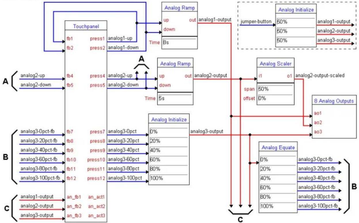
The example SIMPL program is shown below in block diagram form and illustrates three possible applications of the CNXAO-8. To recreate this example refer to “Output Voltage Limit Adjustment” on page 3 and follow the procedure to setup port
A with a span of 5 volts and an offset equal to 0 volts. Also, refer to “Power Up/Reset Voltage Adjustment” on page 2 and make sure jumper X1 is set to 0%. If the jumper is set to 50%, the symbol in the dotted box must be used to initialize values upon start up or reset.
Block Diagram of System Incorporating a CNXAO-8
flowchart
```mermaid
graph TD
    subgraph A
        A1["analog2-up"] --> A2["fb4"]
        A2 --> A3["fb5"]
        A3 --> A4["..."]
        A4 --> A5["..."]
    end

    subgraph B
        B1["analog3-0pct-fb"] --> B2["fb7"]
        B2 --> B3["fb8"]
        B3 --> B4["..."]
        B4 --> B5["analog3-40pct-fb"]
        B5 --> B6["analog3-60pct-fb"]
        B6 --> B7["analog3-80pct-fb"]
        B7 --> B8["analog3-100pct-fb"]
        B8 --> B9["..."]
    end

    subgraph C
        C1["analog1-output"] --> C2["an_fb1"]
        C2 --> C3["an_act1"]
        C3 --> C4["an_fb2"]
        C4 --> C5["an_act2"]
        C5 --> C6["an_fb3"]
        C6 --> C7["an_act3"]

    A1 --> A2
    A2 --> A3
    A3 --> A4
    A4 --> A5
    A5 --> A6
    A6 --> A7
    A7 --> A8
    A8 --> A9
    A9 --> A10

    subgraph A2
        A2 --> A3
        A3 --> A4
        A4 --> A5
        A5 --> A6
        A6 --> A7
        A7 --> A8
        A8 --> A9
        A9 --> A10

    subgraph B
        B1 --> B2
        B2 --> B3
        B3 --> B4
        B4 --> B5
        B5 --> B6
        B6 --> B7
        B7 --> B8
        B8 --> B9

    subgraph C
        C1 --> C2
        C2 --> C3
        C3 --> C4
        C4 --> C5

    subgraph C2
        C2 --> C3
        C3 --> C4

    subgraph D
        D1["jumper-button"] --> D2["Analog Initialize"]
        D2 --> D3["Analog 1-output"]
        D3 --> D4["Analog 2-output"]
        D4 --> D5["Analog 3-output"]
    end

    subgraph D1 & D2 & D3 & D4 & D5 & D6 & D7 & D8 & D9 & D10 & D11 & D12 & D13 & D14 & D15 & D16 & D17 & D18 & D19 & D20 & D21 & D22 & D23 & D24 & D25 & D26 & D27 & D28 & D29 & D30 & D31 & D32 & D33 & D34 & D35 & D36 & D37 & D38 & D39 & D40 & ... & D41 & ... & D42 & ... & D43 & ... & D44 & ... & D45 & ... & D46 & ... & D47 & ... & D48 & ... & D49 & ... & D50 & ... & ... & D51 & ... & ... & ... & ... & ... & ... & ... & ... & ... & ... & ... & ... & ... & ... & ... & ... \\end

    Note: The diagram shows analog input/output connections between analog blocks and analog outputs. Legend indicates the analog block values (e.g., analog1-up, analog2-down) and their corresponding analog outputs (e.g., analog1-output, analog2-output). The red arrows indicate direction of movement or transformation from analog to analog blocks.
The first output, A1, provides a full output range from 0 to 5 volts. As a result, the user can ramp up or down to any voltage in the five-volt range. The second output, A2, produces half the range of A1, because the appropriate signal is passed through a scaler. Thus, the user can only ramp to any voltage between 0 and 2.5 volts. The third output, A3, provides six distinct output voltages. The appropriate signals passed through an initializer produce six incremental one-volt outputs that the user selects with the proper touchpanel button.
How to Create the Program
Configuration Manager
Use the Configuration Manager workspace (Project | Configure System) in SIMPL Windows to select and configure all the devices that need to be included into the system. For this example, from the Control Systems folder in the Device Library select CNMSX-AV with a card cage. Add a CT-3000 from the Touchpanels (Wired) folder; the touchpanel NET ID must be set to 03, shown below. Drag and drop the CT-3000 onto Net Device (Slot #8 on the CNMSX-AV).
NOTE: SIMPL Windows v1.30.01 or later is required to program the control system containing a CNXAO-8. If using an earlier version of SIMPL Windows, Crestron recommends a SIMPL Windows and operating system upgrade. The latest version can be obtained from the Software Downloads page (Simplwin Library) of
the Crestron website (www.crestron.com). New users are required to register in order to obtain access to the FTP site.
System View of the CT-3000 in SIMPL Windows' Configuration Manager

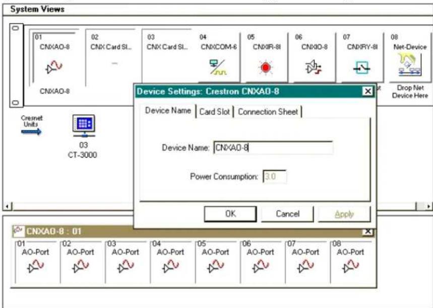
Also add the CNXAO-8 to the system. Drag and drop the card from the Plug-in Control Cards (CNX Series) folder into Slot #1 on the CNMSX-AV, shown below.
System View of the CNXAO-8 in SIMPL Windows' Configuration Manager
Programming Manager
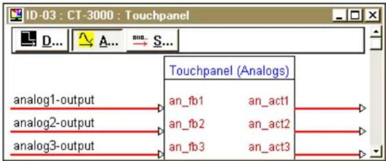
Use the Programming Manager workspace (Project | Program System) in SIMPL Windows to select symbols and assign their respective signals. For this example, a touchpanel was added automatically when the device was added to the system in the Configuration Manager workspace. Expand the Network Modules folder and double click on the CT-3000 for a detail view (alternatively CTRL+D or drag and drop into Detail View). Assign digital and analog signals to the touchpanel as shown after this paragraph.
Detail View of the Digital Signals for the CT-3000 in SIMPL Windows' Programming Manager

flowchart
graph TD
    A["analog1-up"] --> B["fb1"]
    C["analog1-down"] --> D["fb2"]
    E["analog2-up"] --> F["fb3"]
    G["analog2-down"] --> H["fb4"]
    I["analog3-0pct-fb"] --> J["fb5"]
    K["analog3-20pct-fb"] --> L["fb6"]
    M["analog3-40pct-fb"] --> N["fb7"]
    O["analog3-60pct-fb"] --> P["fb8"]
    Q["analog3-80pct-fb"] --> R["fb9"]
    S["analog3-100pct-fb"] --> T["fb10"]
    U["analog1-up"] --> V["press1"]
    W["analog1-down"] --> X["press2"]
    Y["analog2-up"] --> Z["press3"]
    AA["analog2-down"] --> AB["press4"]
    AC["analog3-0pct"] --> AD["press5"]
    AE["analog3-20pct"] --> AF["press6"]
    AG["analog3-40pct"] --> AH["press7"]
    AI["analog3-60pct"] --> AJ["press8"]
    AK["analog3-80pct"] --> AL["press9"]
    AM["analog3-100pct"] --> AN["press10"]
    AO["Touchpanel (Digitals)"] --> AP["[sleep"]]
    AO --> AQ["[wake"]]
Detail View of the Analog Signals for the CT-3000 in SIMPL Windows' Programming Manager
flowchart
graph TD
    A["an_log1-output"] --> B["an_fb1"]
    C["an_log2-output"] --> D["an_fb2"]
    E["an_log3-output"] --> F["an_fb3"]
    B --> G["an_act1"]
    D --> H["an_act2"]
    F --> I["an_act3"]
Expand the Central Control Modules folder. Double click on Slot #1 for a detail view (alternatively CTRL+D or drag and drop into Detail View). Assign signals as shown below.
Detail View of CNXAO-8 in SIMPL Windows' Programming Manager

flowchart
graph LR
    A["analog1-output"] --> B["ao1"]
    C["analog2-output-scaled"] --> D["ao2"]
    E["analog3-output"] --> F["ao3"]
    G["..."] --> H["ao4"]
    I["..."] --> J["ao5"]
    K["..."] --> L["ao6"]
    M["..."] --> N["ao7"]
    O["..."] --> P["ao8"]
All logic symbols necessary for the SIMPL Windows program must be added from the Symbol Library in the Programming Manager workspace. In this example, drag and drop five symbols from the Analog Operations folder into the Logic folder in Program View. Expand the Logic folder and double click on symbol icons for a detail view (alternatively CTRL+D or drag and drop into Detail View). Assign signals as shown below.
Detail View of Two Analog Ramps (S-1 & S-2) in SIMPL Windows' Programming Manager

flowchart
graph LR
    A["analog1-up"] --> B["analog Ramp"]
    C["analog1-down"] --> B
    B --> D["out"]
    B --> E["down"]
    B --> F["[mute"]]
    B --> G["Time: 8s"]
    H["analog1-output"] --> I

flowchart
graph LR
    A["analog2-up"] --> B["up"]
    C["analog2-down"] --> D["down"]
    E["[mute"]] --> F["[mute"]]
    G["Time 5s"] --> H
    I["analog2-output"] --> J
    K["Analog Ramp"] --> L
NOTE: For a more descriptive symbol name, as shown in the previous illustration, right mouse click on the symbol icon in the Logic folder in Program View and select Edit Symbol Comment (alternatively, highlight the icon and depress Ctrl+R or
Tab). Enter a new descriptive name in the "Enter Symbol Comment" dialog box and click OK.
Detail View of a Analog Scaler (S-3) in SIMPL Windows' Programming Manager

flowchart
graph LR
    A["analog2-output"] --> B["Analog Scaler"]
    B --> C["analog2-output-scaled"]
    D["span 50%"] --> E["[div"]]
    F["offset 0%"] --> G
Detail View of a Analog Initialize Symbol (S-4) in SIMPL Windows' Programming Manager

flowchart
graph LR
    A["analog3-0pct"] --> B["0%"]
    C["analog3-20pct"] --> D["20%"]
    E["analog3-40pct"] --> F["40%"]
    G["analog3-60pct"] --> H["60%"]
    I["analog3-80pct"] --> J["80%"]
    K["analog3-100pct"] --> L["100%"]
    M["analog3 Initialize"] --> N["analog3-output"]
    O["value2"] --> P
    Q["value3"] --> R
    S["value4"] --> S
    T["value5"] --> U
    V["value6"] --> V
Detail View of a Analog Equate Symbol (S-5) in SIMPL Windows' Programming Manager

flowchart
graph LR
    A["analog3-output"] --> B["0%"]
    A --> C["20%"]
    A --> D["40%"]
    E["value3"] --> F["60%"]
    G["value4"] --> H["80%"]
    I["value5"] --> J["100%"]
    K["value6"] --> L["analog3-0pct-fb"]
    K --> M["analog3-20pct-fb"]
    K --> N["analog3-40pct-fb"]
    K --> O["analog3-60pct-fb"]
    K --> P["analog3-80pct-fb"]
    K --> Q["analog3-100pct-fb"]
The example SIMPL program is provided with a sixth logic symbol, Analog Initialize. The purpose of this symbol is to initialize the value so that devices receiving the analog signal do not exhibit drastic voltage swings upon start up or reset. Implement this symbol only if the jumper is set to 50%. Also, replace the input, "jumper-button", with a logic constant, "1".
Detail View of a Analog Initialize Symbol (S-6) in SIMPL Windows' Programming Manager

flowchart
graph LR
    A["jumper-button"] --> B["Analog Initialize"]
    B --> C["50%"]
    B --> D["50%"]
    B --> E["50%"]
    F["analog1-output"] --> G
    H["analog2-output"] --> I
    J["analog3-output"] --> K
Problem Solving
Troubleshooting
The table below provides corrective action for possible trouble situations. If further assistance is required, please contact a Crestron technical support representative.
CNXAO-8 Toubleshooting
| TROUBLE | POSSIBLE CAUSE(S) | CORRECTIVE ACTION |
| CNXAO-8 does not function properly or at all. | CNX Control System is not receiving power. | Verify power to CNX Control System. |
| Circuit card is not properly seated in slot. | Verify CNXAO-8 is properly inserted into CNX Control System slot per procedures in this Operations Guide. | |
| Wiring from CNXAO-8 to controlled equipment is incorrect. | Verify wiring; connect the proper pins from CNXAO-8 to each external piece of equipment. | |
| Output voltages are not properly adjusted. | Follow the output voltage limit adjustment procedure in this Operations Guide. | |
| Programming error. Check SIMPL Windows program. | ||
Further Inquiries
If after reviewing this Operations Guide for the CNXAO-8, you cannot locate specific information or have questions, please take advantage of Crestron's award winning technical support team by calling:
- In the US and Canada, call Crestron's corporate headquarters at 1-888-CRESTRON [1-888-273-7876] or 1-201-767-3400.
• In Europe, call Crestron International at +32-15-50-99-50.
• In Asia, call Crestron Asia at +852-2341-2016.
• In Latin America, call Crestron Latin America at +5255-5093-2160.
• In Australia, call Crestron Pacific at +613-9480-2999.
For local support from exclusive Crestron factory-trained personnel in New Zealand call Amber Technologies at +649-410-8382.
Return and Warranty Policies
Merchandise Returns / Repair Service
- No merchandise may be returned for credit, exchange, or service without prior authorization from CRESTRON. To obtain warranty service for CRESTRON products, contact the factory and request an RMA (Return Merchandise Authorization) number. Enclose a note specifying the nature of the problem, name and phone number of contact person, RMA number, and return address.
- Products may be returned for credit, exchange, or service with a CRESTRON Return Merchandise Authorization (RMA) number. Authorized returns must be shipped freight prepaid to CRESTRON, Cresskill, N.J., or its authorized subsidiaries, with RMA number clearly marked on the outside of all cartons. Shipments arriving freight collect or without an RMA number shall be subject to refusal. CRESTRON reserves the right in its sole and absolute discretion to charge a 15% restocking fee, plus shipping costs, on any products returned with an RMA.
- Return freight charges following repair of items under warranty shall be paid by CRESTRON, shipping by standard ground carrier. In the event repairs are found to be non-warranty, return freight costs shall be paid by the purchaser.
CRESTRON Limited Warranty
CRESTRON ELECTRONICS, Inc. warrants its products to be free from manufacturing defects in materials and workmanship under normal use for a period of three (3) years from the date of purchase from CRESTRON, with the following exceptions: disk drives and any other moving or rotating mechanical parts, pan/tilt heads and power supplies are covered for a period of one (1) year; touchscreen display and overlay components are covered for 90 days; batteries and incandescent lamps are not covered.
This warranty extends to products purchased directly from CRESTRON or an authorized CRESTRON dealer. Purchasers should inquire of the dealer regarding the nature and extent of the dealer's warranty, if any.
CRESTRON shall not be liable to honor the terms of this warranty if the product has been used in any application other than that for which it was intended, or if it has been subjected to misuse, accidental damage, modification, or improper installation procedures. Furthermore, this warranty does not cover any product that has had the serial number altered, defaced, or removed.
This warranty shall be the sole and exclusive remedy to the original purchaser. In no event shall CRESTRON be liable for incidental or consequential damages of any kind (property or economic damages inclusive) arising from the sale or use of this equipment. CRESTRON is not liable for any claim made by a third party or made by the purchaser for a third party.
CRESTRON shall, at its option, repair or replace any product found defective, without charge for parts or labor. Repaired or replaced equipment and parts supplied under this warranty shall be covered only by the unexpired portion of the warranty.
Except as expressly set forth in this warranty, CRESTRON makes no other warranties, expressed or implied, nor authorizes any other party to offer any other party to offer any warranty, including any implied warranties of merchantability or fitness for a particular purpose. Any implied warranties that may be imposed by law are limited to the terms of this limited warranty. This warranty statement supersedes all previous warranties.
Trademark Information
All brand names, product names, and trademarks are the sole property of their respective owners. Windows is a registered trademark of Microsoft Corporation. Windows95/98/Me/XP and WindowsNT/2000 are trademarks of Microsoft Corporation.
This page intentionally left blank.
This page intentionally left blank.
- CNX Analog Output Expansion Card
- Operations Guide
- Contents
- CNX Analog Output Expansion Card: CNXAO-8 1
- CNX Analog Output Expansion Card: CNXAO-8
- Description
- Functional Description
- Physical Description
- Leading Specifications
- Setup
- Power Up/Reset Voltage Adjustment
- Installation
- Output Voltage Limit Adjustment
- Lower Limit Adjustment
- Upper Limit Adjustment
- Fine Tune the Voltage Span
- Programming with SIMPL™ Windows®
- How the Program Works
- How to Create the Program
- Configuration Manager
- Programming Manager
- Problem Solving
- Troubleshooting
- Further Inquiries
- Return and Warranty Policies
- Merchandise Returns / Repair Service
- CRESTRON Limited Warranty
- Trademark Information
Brand : Crestron
Model : CNXAO-8
Category : Electronic board