
OCS 100W - Motion detector Extron - Free user manual and instructions
Find the device manual for free OCS 100W Extron in PDF.


| Product Type | Motion Detector |
| Brand | Extron |
| Model | OCS 100W |
| Detection Method | Passive Infrared (PIR) |
| Detection Range | Up to 12 meters (40 ft) |
| Detection Angle | 90 degrees |
| Power Source | 9V DC (battery or adapter) |
| Battery Type | 9V alkaline (not included) |
| Standby Current | < 50 µA |
| Alarm Output | NC/NO relay, 24V DC/1A max |
| Mounting | Wall or ceiling mount |
| Operating Temperature | -10°C to 50°C (14°F to 122°F) |
| Humidity | Up to 90% non-condensing |
| Dimensions (H x W x D) | 100 x 70 x 50 mm (3.9 x 2.8 x 2.0 in) |
| Weight | 120 g (4.2 oz) |
| Certifications | CE, FCC |
| Maintenance | Monthly cleaning of lens with soft dry cloth |
| Cleaning | Do not use solvents or abrasive cleaners |
| Safety | Low voltage, safe for indoor use |
| Spare Parts | None user-serviceable; contact support for replacement |
| Repairability | Not repairable by user; professional service required |
| General Info | Designed for indoor security and automation |
| Includes | Detector, mounting hardware, manual |
Frequently Asked Questions - OCS 100W Extron
User questions about OCS 100W Extron
0 question about this device. Answer the ones you know or ask your own.
Ask a new question about this device
Download the instructions for your Motion detector in PDF format for free! Find your manual OCS 100W - Extron and take your electronic device back in hand. On this page are published all the documents necessary for the use of your device. OCS 100W by Extron.
USER MANUAL OCS 100W Extron
Occupancy Sensor OCS 100W • Setup Guide
The OCS 100W is a dual technology occupancy sensor that can be used to automate meeting and presentation spaces when used with Extron control products. The OCS is equipped with ultrasonic (US), infrared (PIR), and photocell sensors that can be used together to report ambient light conditions and room occupancy. Sensors can be wired directly to Extron controller products equipped with Digital I/Os ports or via eBUS, when using optional eBUS interface accessories.
The OCS requires 24 VDC for operation. If local 24 V power is not available, use the included 12 V to 24 V, USB 5 V to 24 V power converter.
NOTE: The OCS 100W is designed to detect occupancy using both the PIR and US sensors with their default settings to avoid false detections.
Front Panel Features and Control


Figure 1. OCS 100W Front Panel Features Figure 2. OCS 100W Controls
- Ultrasonic Sensors (2) — Detect movement in the room, based on ultrasonic sound waves. The US sensor emits ultrasonic sound waves into an area and measures the speed of their return to detect the presence of people. Frequency changes are caused by the movement of people, which is detected by the US waves.
• Ultrasonic (US) Green LED status indicator — Flashes when the ultrasonic sensors detect occupancy.
• Infrared/Photocell Sensor and Fresnel Lens —
• The Fresnel lens diffracts the incoming light and directs the light to the infrared sensor behind it.
- The Infrared (PIR) sensor detects the presence of people based on the difference between the heat generated by moving people versus the ambient room temperature.
• Infrared (PIR) Red LED status indicator — Flashes when the infrared sensor detects occupancy.
- Removable Front Cover — Conceals all controls and DIP switches.
• DIP Switches (A) —
| A Switch Function OFF ON Note | ||||
| 1 Not used *Not used N | Not used Switch is not used. | |||
| 2 Occupancy detection behavior - Dual Technology Mode | *Mutually exclusive (requires both PIR and US detection) | Independent (either PIR or US detection) | If A2 is set to OFF, both the PIR and US sensors must be triggered (simultaneously) before the OCS reports an occupancy signal. If A2 is set to ON, the OCS reports occupancy based on only one of the sensors being triggered. When only one sensor is desired, set A2 to ON and adjust the dials accordingly. If A2 is ON, false detection when the room is not occupied increases. | |
| 3 Sensor status indicators | *LEDs enabled LEDs disabled | Setting A3 to OFF provides a visual notification whenever the PIR or US sensors are triggered. When the visual LED indicators are a distraction or you want to disable the flashing LEDs, A3 should be set to ON. | ||
| 4 Automatic adjust reset | *Retain learned sensor adjustments | Erase all learned settings (toggle ON, then OFF) | Only applicable when Timer (B3) or Sensitivity adjust (B4) or both are set to Automatic mode (OFF). Toggling A4 ON then OFF will reset any stored learned adjustments. | |
*Default and recommended settings
Occupancy Sensor OCS 100W • Setup Guide (Continued)
• DIP Switches (B) — (see figure 2 on the previous page)
| B Switch Function Settings Note | ||||||
| 1 Timer Setting (B1 and B2 switches must be set together) | *8 minutes: OFF | 4 minutes: OFF | 15 minutes: ON | 30 minutes: ON | In manual mode only (B3 set to ON), set the amount of time before the sensor triggers OFF when there is no occupancy detected. In automatic mode (B3 set to OFF) the timer settings are ignored. | |
| B Switch Function OFF ON | ||||||
| 3 | Timer adjust | Automatic | *Manual | Applies to the Timer (blue), Infrared sensitivity (red), and Ultrasonic sensitivity (green) adjustment dials.Setting to Manual mode allows for more predicted behavior and is better suited for automating AV applications.Setting to Automatic mode allows the sensor to learn over time the ideal timer and sensitivity adjustments for the space and usage trends. This is better suited for automating lighting applications.All adjustment dials are disabled when set to Automatic (OFF). | ||
| 4 Sensitivity adjust Automatic *Manual | ||||||
*Default and recommended
NOTE: B3 must be set to ON for Manual mode, in order to adjust the timer switches manually. B4 must be set to ON for Manual mode, in order to adjust the infrared sensitivity and US sensitivity dials manually.
- Timer Setting (B1 and B2) — The occupancy sensor has a built-in timer feature. In Manual mode (B3 set to ON), set the B1 and B2 DIP Switches together, as shown in the table above, to set the amount of time before the sensor triggers OFF. When the sensor detects motion, it instantly triggers ON.
Once occupancy is no longer detected, the timer begins. If no motion is detected and the timer expires, then the sensor triggers OFF.
NOTE: If it takes too long for the OCS to turn off when the room is unoccupied, adjust the timer to 8 or 4 minutes and extend the timer via the configuration of the connected control processor. This setup reduces false detection.
- Blue Timer Test Button —
- To enable an 8 second timer test mode, push the blue button once. The test mode lasts for 1 hour, and then automatically resets to the dip switch settings.
- To cancel the 8 second test mode, push and hold the blue button until the red LED flashes, returning the OCS to the settings defined by the dip switches.
• Red Infrared Sensitivity Dial — Adjust this dial to increase or decrease infrared sensitivity.
• Turn counter-clockwise (CCW) to decrease sensitivity. Major movements are needed to detect occupancy.
• Turn clockwise (CW) to increase sensitivity. Minor movements are detected as occupancy.
• The factory default setting is at 75%.
- Green Ultrasonic Sensitivity Dial — Adjust this dial to increase or decrease ultrasonic sensitivity.
• Turn counterclockwise (CCW) to decrease sensitivity. Major movements are needed to detect occupancy.
• Turn clockwise (CW) to increase sensitivity. Minor movements are detected as occupancy.
• The factory default setting is at 100%.
- Blue Photocell Sensitivity Dial — Photocell prevents the sensor from triggering on when the area is adequately lit with natural light and when motion is detected. The sensor must be mounted directly over an area that is representative of the average, natural room lighting. Before setting the photocell control, wait until the natural light is brightest (optional). Adjust this dial to increase or decrease photocell sensitivity.
• Turn counterclockwise to decrease photocell sensitivity, causing it to activate with less light.
• Turn clockwise to increase photocell sensitivity, requiring brighter light to activate the sensor.
• Factory default is 100% (full clockwise) — Photocell sensor is disabled.
• Range — 10 to 1000 lux
Recommended Setup

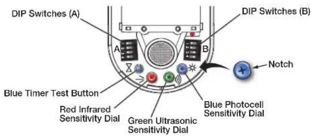
Figure 3. OCS 100W Front Panel Features and Controls
With the OCS in the default or recommended settings (A2 OFF), the OCS requires both the IR sensor AND the US sensor to detect occupancy to turn ON. Only one sensor (PIR or US) needs to trigger to reset the timer for the OCS to remain ON while the room is still occupied. When the OCS is in the OFF state, no occupancy is detected.
Follow these steps to set up the OCS to detect occupancy with minimal false detection:
NOTE: We recommend using the OCS 100W in the default settings when beginning the setup or the test mode. If needed, adjust slightly from the default sensitivity settings.
- Keep all the DIP switches and rotary dials in the default positions.
- Set the OCS in Test Mode.
- Enter the room several times to verify if the IR detector is detecting movement (red LED flashes).
• If the red LED flashes when entering the room, the default red infrared sensitivity dial is set correctly.
- Verify the red LED flashes with movement throughout the room.
- Turn the red infrared sensitivity dial to decrease or increase IR sensitivity, until the red LED only flashes when entering the room or making movements throughout the room.
• To avoid false detections when the room is unoccupied, do not make the sensor too sensitive.
-
Enter the room and verify if the US detector is detecting movement (green LED flashes).
-
If the green LED flashes when entering the room, the default green ultrasonic range dial is set correctly. This sensor is very sensitive.
- Verify the green LED flashes with movement throughout the room.
-
Turn the green ultrasonic range dial to decrease or increase US sensitivity, until the green LED only flashes when entering the room or making movements throughout the room.
• To avoid false detections when the room is unoccupied, do not make the sensor too sensitive. -
Leave the room and close the door. Wait until the Digital output state, relay or red and green LEDs stay OFF. Wait several minutes to ensure there are no false detections.
-
If the door remains open, the US sensor may detect changes.
-
If possible, wait longer, to confirm no IR or US change is registered.
-
Enter the room again to confirm the Digital output state, relay, red, or green LEDs turn ON.
NOTE: After going through these steps and verifying the OCS is set up to accommodate the room, do not adjust the DIP switches or dials.
Automatic Mode
Out of the box, the OCS 100W can be set up in Automatic Mode, where no manual sensitivity adjustments are needed and sensitivity learning and adjustments are made automatically. For simple setup, we recommend keeping the OCS in the default settings and flipping the B4 Dip switch to the OFF (Auto) position. The OCS is ready to mount (see Installation on page 5).
Occupancy Sensor OCS 100W • Setup Guide (Continued)
Sensor Placement and Installation Options
When placing the sensor in a room, be sure the sensor is not aimed out through a door. The sensor can detect hallway traffic, causing false triggers. PIR sensors trigger in response to changes in the amount of IR arriving from any of their segments of view within a direct line of sight from the sensor. US sensors trigger in response to changes in the frequency of reflected ultrasonic waves, caused by movement within the space.
NOTE: See Troubleshooting on page 7 if you experience false triggers.
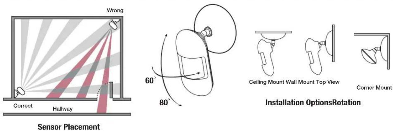
Figure 4. Sensor Placement and Installation Diagrams
NOTE: Mount the OCS 6 to 8 feet (1.8 to 2.4 m) away from HVAC vents and high air flow areas
Sensor Coverage

Figure 5. Sensor Coverage Diagrams
OCS 100W Parts
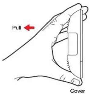

Figure 6. OCS 100W Parts
Installation
ATTENTION:
Only connect to Class III SELV systems.
Occupancy Sensor OCS 100W • Setup Guide (Continued)
PC 1224 Wiring
ATTENTION:
The OCS 100W requires 24 VDC. If the sensors are connected to a device that does not provide 24 VDC, use the included PC 1224 power module:
-
Connect a 12 VDC power source to the 12 VDC input on the supplied PC 1224 power converter (see figure 8), or power via the USB type-C 5 V input (see figure 9).
-
Wire the PC 1224 24 VDC, 75 mA max connector to the black and red wires on the OCS 100W.
NOTE: When the PC 1224 is powered via the USB 5 V input, the 24 V output is rated at 35 mA.
A 12 VDC, 1.25 A max pass-through is available to power additional 12 VDC devices, only if powered from the 12 V input.
OCS 100W Wiring

Figure 8. OCS 100W External Power Supply Wiring Diagram

flowchart
graph LR
    A["PGE"] --> B["Extron TLS 1025M\n10" Wall Mount\nTouchLink Scheduling\nTouchpanel"]
    B --> C["Digital Input"]
    C --> D["USB"]
    D --> E["Extron PC 1224\nPower Module\nExtron\nPC 1224\n+24 V OUT (Red)\n73 mA MAX\n+1.25 A MAX\n-1.25 A MAX\nGround (Black)\n33-2749-01 B\nwww.extron.com"]
    E --> F["Extron OCS 100W\nOccupancy Sensor"]
    F --> G["Occupancy Control\nSignal (Blue)"]
Figure 9. OCS 100W USB Power Wiring Diagram
| Wire Connections Note | ||
| Power | ||
| Black Ground | Shared with all of the outputs. | |
| Red +24 VDC | Power input. | |
| Occupancy Control Outputs | ||
| Blue Occupancy control output When wiring the blue wire of the OCS to Extron products with Digital or FLEX Input ports, configure the ports as Input without pull up. The sensor provides approximately 21 VDC in the ON state and 0 VDC in the OFF state. Use the shared black ground wire. | ||
| Blue/White Common Relay contacts could be used to trigger third party devices, such as HVAC, based on occupancy. | ||
| Black/White Normally closed when unoccupied | ||
| Yellow/White Normally open when unoccupied | ||
| Occupancy and Lighting Output | ||
| Gray Occupancy and photocell control output | Typically used for lighting applications. When wiring the gray wires of the OCS to Extron products with Digital or FLEX Input ports, configure the ports as Input without pull up. The output state will remain OFF 0 VDC when occupancy is detected but there is high amount of ambient or natural light in the room. Only when there is low or no ambient or natural light in the room and occupancy is detected will the output state trigger ON 21 VDC. Use the shared black ground wire. | |
Troubleshooting
| Problem | Possible Cause | Test | Solution |
| Sensor remains ON. | Constant noise. | Reduce both green and red knobs by 1/8 (15%) turn orremove noise source. | Move sensor to a less noisy areawithin the room. |
| Sensor remains OFF. | Sensitivity is set too low. | Increase both green and redknobs by 1/8 (15%) turn. | Move sensor. If the A2 DIPswitch is set to OFF, set greenand red US/IR sensitivity dials tonormal levels. |
| Sensor remains on too long. | Timer setting too high. | Check DIP switch settings. | Reduce timer setting. |
| Hallway traffic turns sensoron. | Infrared sensor can see intothe hallway. | Put sensor in timer test modeand walk the hallway. | Move sensor, so it cannot seeinto the hallway. |
Safety Instructions
For information on safety guidelines, regulatory compliances, EMI/EMF compatibility, accessibility, and related topics, see the Extron Safety and Regulatory Compliance Guide on the Extron website.
FCC Class A Notice
This equipment has been tested and found to comply with the limits for a Class A digital device, pursuant to part 15 of the FCC rules. The Class A limits provide reasonable protection against harmful interference when the equipment is operated in a commercial environment. This equipment generates, uses, and can radiate radio frequency energy and, if not installed and used in accordance with the instruction manual, may cause harmful interference to radio communications. Operation of this equipment in a residential area is likely to cause interference. This interference must be corrected at the expense of the user.
NOTE: For more information on safety guidelines, regulatory compliances, EMI/EMF compatibility, accessibility, and related topics, see the Extron Safety and Regulatory Compliance Guide on the Extron website.
Power Attention
ATTENTION:
For information on safety guidelines, regulatory compliances, EMI/EMF compatibility, accessibility, and related topics, see the Extron Safety and Regulatory Compliance Guide on the Extron website.
- Occupancy Sensor OCS 100W • Setup Guide
- Front Panel Features and Control
- Occupancy Sensor OCS 100W • Setup Guide (Continued)
- Recommended Setup
- Automatic Mode
- Sensor Placement and Installation Options
- Sensor Coverage
- Installation
- ATTENTION:
- PC 1224 Wiring
- OCS 100W Wiring
- Safety Instructions
- FCC Class A Notice
- Power Attention
Brand : Extron
Model : OCS 100W
Category : Motion detector