
K60 TU KX A - Range hood LA GERMANIA - Free user manual and instructions
Find the device manual for free K60 TU KX A LA GERMANIA in PDF.


| Product Type | Wall-mounted range hood |
| Model | K60 TU KX A |
| Brand | La Germania |
| Width | 60 cm |
| Depth | 50 cm |
| Height (min-max) | 65 - 115 cm |
| Weight | 15 kg |
| Power Supply | 220-240 V, 50 Hz |
| Motor Power | 200 W |
| Extraction Capacity (max) | 600 m³/h |
| Noise Level (max) | 65 dB |
| Energy Class | B |
| Lighting | LED, 2 x 3 W |
| Control Type | Electronic touch controls |
| Number of Speeds | 3 + intensive mode |
| Grease Filter Type | Aluminum, washable |
| Charcoal Filter | Optional, replaceable |
| Duct Diameter | 150 mm |
| Safety Features | Automatic shut-off timer, safety cut-off |
| Installation | Wall-mounted, vertical or horizontal exhaust |
| Spare Parts Availability | Available through authorized service centers |
Frequently Asked Questions - K60 TU KX A LA GERMANIA
User questions about K60 TU KX A LA GERMANIA
0 question about this device. Answer the ones you know or ask your own.
Ask a new question about this device
Download the instructions for your Range hood in PDF format for free! Find your manual K60 TU KX A - LA GERMANIA and take your electronic device back in hand. On this page are published all the documents necessary for the use of your device. K60 TU KX A by LA GERMANIA.
USER MANUAL K60 TU KX A LA GERMANIA
GB Use and maintenance instructions
| Italiano | pag. | 3 |
| English | page | 14 |
| Español | pag. | 14 |
| Français | pag. | 14 |
| Deutsch | s. | 15 |
| Nederlands | pg. | 15 |
| Português | pág. | 15 |
DISPOSAL OF OLD ELECTRICAL AP-
PLIANCES
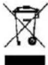
The European Directive 2002/96/EC on Waste Electrical and Electronic Equipment (WEEE), requires that old household electrical appliances must not be disposed of in the normal unsorted municipal waste stream. Old appliances must be collected separately in order to optimise the recovery and recycling of the materials they contain and reduce the impact on human health and the environment. The crossed out "wheeled bin" symbol on the product reminds you of your obligation, that when you dispose of the appliance it must be separately collected. Consumers should contact their local authority or retailer for information concerning the correct disposal of their old appliance.
RECOGIDA DE LOS
ELECTRODOMÉSTICOS

Fig. 1
2.3 - ILLUMINAZIONE
Fig. 2A

Fig. 2B

Fig. 3
3.4 - INSTALLAZIONE
Fig. 4


Fig. 6
C - CONNESSIONE ELETTRICA ALLA RETE:
Fig. 8

Fig. 9
4 - SPECIFICHE TECNICHE
4.1 - CARATTERISTICHE GENERALI
- IMPIANTO ELETTRICO A NORME INTERNAZIONALI
- TRE VELOCITA' DI ESERCIZIO
- STANDARD DI RIFERIMENTO AI FINI DELLA DIRETTIVA E.M.C. 89/336: EN55014, EN60555-2
- STANDARD DI RIFERIMENTO AI FINI DELLA DIRETTIVA L.V.D. 73/23, CON INT. 93/68: EN60335-1, EN60335-2-31
SCHEMA ELETTRICO COMANDO ROTATIVO

INDEX
1 - USE INSTRUCTIONS PAGE 16
| 1.1 | ROTATIVE CONTROL | |
| PANEL | PAGE 16 | |
| 1.2 | SAFETY | PAGE 16 |
| 1.3 | CLEANING | PAGE 18 |
INDICE
1 - INSTRUCCIONES
PARA EL USO PAG 16
| 1.1 CUADRO DE MANDOS | |
| ROTATIVO | PAG 16 |
| 1.2 SEGURIDAD | PAG 16 |
| 1.3 LIMPIEZA | PAG 18 |
INDEX
1 - INSTRUCTIONS
POUR L'UTILISATION PAG 16
| 1.1 TABLEAU DE COMMANDES | |
| ROTATIFS | PAG 16 |
| 1.2 SÉCURITÉ | PAG 16 |
| 1.3 NETTOYAGE | PAG 18 |
2 - MAINTENANCE
| INSTRUCTIONS | PAGE | 20 |
| 2.1 WARNINGS | PAGE | 20 |
| 2.2 ANTI-GREASE FILTERS | PAGE | 20 |
| 2.3 LIGHTING | PAGE | 22 |
| 2.4 STAINLESS STEEL PANEL | PAGE | 22 |
2.1 WAARSCHUWING PG 21
2.2 VETFILTERS PG 21
2.3 VERLICHTING PG 23
2.4 INOX PANEEL PG 23
2 - INSTRUÇÕES PARA A
MANUTENÇÃO PÁG.21
2.1 ADVERTÊNCIAS PÁG. 21
2.2 FILTROS ANTI
GORDURA PÁG. 21
A - ON/OFF Lighting control. Turn the knob clockwise from position 0 to 1 to switch on the light
B - Turn the knob clockwise from the position 0 (OFF) to switch on the hood as follows:
- First Speed
- Second speed
- Third Speed
A - Do not cook at the flame under the hood.
B - Constantly check oil overheating while using the deep fryer in order to prevent it from catching fire.
C - Before carrying out any cleaning operation disconnect the appliance by unplugging it or by switching off the circuit breaker.
D - In the case in which the hood and other apparatuses that emit fumes are being used in the room, do not supply with electric energy.
The room needs to be aerated.
E - Do not leave the cooker on if it is not being used
F - The hood has been designed to remove the kitchen smells; any other additional use shall be regarded as non-intended.
1.2 - SEGURIDAD
1 - INSTRUÇÕES PARA O USO
1.1 - QUADRO COMANDO ROTATIVO (FIG. A)
G - It is advisable to turn on the hood a bit before starting to cook and leave it on for approx. 15 minutes after or at least until the smell is completely removed.
- Use only a damp cloth with neutral liquid detergent.
- Do not use wet sponges or cloths, water jets, thinners, solvents, alcohol or abrasive substances.
1.3 - LIMPIEZA
Unplug the appliance or switch off the circuit breaker before carrying out maintenance operations.
2.2 - METALLIC ANTI-GREASE FILTERS
- The 3 filters must be washed at least once a month with hot water and detergent.
- It can also be washed in the dish-washer.
- Open by means of the handle (Fig.1).
2 - MANTENIMIENTO
2.1 - ADVERTENCIA
Fig. 1
2 - WARTUNG
2.1 - HINWEIS
- To replace the two lamps remove the two anti-grease filters in order to reach the lamp holder and unscrew the lamp or lamps (Fig 2A).
- Replace the lamp with one that has the same features (40w E14) because one with major power may cause severe damage to the electrical system.
HALOGEN LIGHTING 1
- turn the glass and the light unit flange in an anticlockwise direction. (Fig. 2B).
HALOGEN LIGHTING 2
- remove the glass raising it with a screwdriver (Fig.2C)
Replace the lamp with one that has the same features (20W Max) because one with major power cause severe damage to the electrical system.
2.4 - STAINLESS STEEL PANEL (only for versions where envisioned)
- To wash the stainless steel panel, unscrew the screws and use a non-aggressive detergent (Fig. 3).
2.3 - ILUMINACION
Fig. 2A
Fig. 2B

2.3 - BELEUCHTUNG
Fig. 2C

Fig. 3
3 - INSTALLING INSTRUCTIONS
3.1 - GENERAL INFORMATION
This hood has been arranged to be installed above a cook top. It can be used on the ASPIRATING types (external exhaust).
We suggest to have installation carried out by qualified personnel, in compliance with all the current regulations and in particular with the ones concerning air exhaust. The manufacturer cannot be held liable for damages caused by improper installation or if it has not been carried out according to the state-of-the-art.
A - Do not connect the appliance discharge to exhaust ducts of smokes produced by combustion that is not supplied by electrical power.
B - The minimum safety distance between the cooking counter and the hood is 65 cm.
C - In the case in which both the hood and apparatuses emit fumes, do not operate electrical energy. A sufficient aeration of the setting needs to be created.
Proper use without risks is obtained when the maximum depression of the room does not exceed 4 Pa (4x10 bar).
3.2 - SEGURIDAD
A - Complete hood casing
B - Reduction fitting dia. 150/120
C - Upper stack wall clamp
D - Upper telescopic stack
E - Lower telescopic stack
F - Bag with accessories and screws
3.3 - COMPONENTES
Deutsch Nederlands Português
BAUTEILE
COMPONENTEN
COMPONENTES

3 - HINWEISE ZUR INSTAL- LATION
3.1 - ALLGEMEINES
- Mount the 120/150 reduction fitting whenever the air discharge tube is ∅125.(Fig.4)
- Hang the hood case firmly to the wall by means of the two M5 x 40 screws included in the supply and remember that the cook top must be of at least 6.5cm far from the lower side of the hood (Fig. 5-6).
3.4 - INSTALACION
Fig. 4

Fig. 5
3.4 - INSTALLATION
A - POSITIONIERUNG DER ABZUGS-HAUBE
- Fix the upper fireplace anchoring rod at the height desired, using the two supplied M5 x 40 screws.
Fig. 7
C - HOW TO CONNECT TO THE ELECTRICAL MAIN:
Check to see that the main voltage complies with the one required by the hood, which is indicated on the tag that is applied on the internal side of the appliance.
Assemble a suitable plug on the wire or insert a proper power two-pole switch if it is to be directly connected to the main with a 3mm minimum opening between contacts between the main and the appliance. All the above-mentioned electrical parts must comply with the current standards.
The yellow/green earthing cable must not be interrupted.
C - CONEXION ELECTRICA A LA RED.
Check lights and motor start-up in the several speeds.
D - CONTROL FUNCIONAL :
- Slide the upper telescopic stack inside the lower telescopic stack. (Fig. 8).
- Position the lower telescopic stack on the hood case.
- Raise the upper telescopic stack and fix it by means of the two M3.9 x 9.5 screws included in the supply (Fig. 9).
Fig. 8
4 - TECHNICAL SPECIFICATIONS
4.1 - GENERAL CHARACTERISTICS
- ELECTRICAL SYSTEM ACCORDING TO THE INTERNATIONAL REGULATIONS
- 3 OPERATING SPEEDS
- REFERENCE STANDARDS ACCORDING TO THE E.M.C. 89/336: EN55014, EN60555-2 DIRECTIVES
- REFERENCE STANDARDS ACCORDING TO THE L.V.D. 73/23, WITH INT. 93/68: EN60335-1, EN60335-2-31 DIRECTIVES
4 - ESPECIFICAS TECNICAS
4.1 - CARACTERISTICAS GENERALES.
- INSTALACION ELECTRICA SEGUN LOS NORMAS INTERNACIONALES.
- 3 VELOCIDADES DE FUNCIONA- MIENTO
- ESTÓNDAR DE REFERENCIA SEGUN LA DIRECTIVA E.M.C. 89/336, EN55014, EN60555-2
- ESTÁNDAR DE REFERENCIA SEGUN LA DIRECTIVA L.V.D. 73/23, CON INT. 93/68: EN60335-1, EN60335-2-31
4 - DETAILS TECHNIQUES
4.1 - CARACTERISTIQUES GENERALES
- INSTALLATION ELECTRIQUE SELON LES REGLEMENTS INTERNATIONAUX
- 3 VITESSES D'OPÉRATION
- STANDARD DE REFERENCE POUR LA DIRECTIVE E.M.C. 89/336: EN55014, EN60555-2
- STANDARD DE REFERENCE POUR LA DIRECTIVE L.V.D. 73/23, AVEC INT. 93/68: EN60335-1, EN60335-2-31
ROTATIVE CONTROL WIRING DIAGRAM
ESQUEMA ELÉCTRICO DE MANDOS ROTATIVO
SCHÉMA ÉLECTRIQUE DE COMMANDES ROTATIFS




- 2.3 - ILLUMINAZIONE
- 3.4 - INSTALLAZIONE
- C - CONNESSIONE ELETTRICA ALLA RETE
- SPECIFICHE TECNICHE
- 4.1 - CARATTERISTICHE GENERALI
- INDEX
- USE INSTRUCTIONS PAGE 16
- INDICE
- INSTRUCCIONES
- INSTRUCTIONS
- MAINTENANCE
- INSTRUÇÕES PARA A
- 1.2 - SEGURIDAD
- INSTRUÇÕES PARA O USO
- 1.1 - QUADRO COMANDO ROTATIVO (FIG. A)
- 1.3 - LIMPIEZA
- 2.2 - METALLIC ANTI-GREASE FILTERS
- MANTENIMIENTO
- 2.1 - ADVERTENCIA
- WARTUNG
- 2.1 - HINWEIS
- HALOGEN LIGHTING 1
- HALOGEN LIGHTING 2
- 2.4 - STAINLESS STEEL PANEL (ONLY FOR VERSIONS WHERE ENVISIONED)
- 2.3 - ILUMINACION
- 2.3 - BELEUCHTUNG
- INSTALLING INSTRUCTIONS
- 3.1 - GENERAL INFORMATION
- 3.2 - SEGURIDAD
- 3.3 - COMPONENTES
- HINWEISE ZUR INSTAL- LATION
- 3.1 - ALLGEMEINES
- 3.4 - INSTALACION
- 3.4 - INSTALLATION
- A - POSITIONIERUNG DER ABZUGS-HAUBE
- TECHNICAL SPECIFICATIONS
- 4.1 - GENERAL CHARACTERISTICS
- ESPECIFICAS TECNICAS
- 4.1 - CARACTERISTICAS GENERALES
- DETAILS TECHNIQUES
- 4.1 - CARACTERISTIQUES GENERALES
Brand : LA GERMANIA
Model : K60 TU KX A
Category : Range hood