
GW90746 - Motion detector Gewiss - Free user manual and instructions
Find the device manual for free GW90746 Gewiss in PDF.


| Product Type | Motion Detector |
| Brand | Gewiss |
| Model | GW90746 |
| Power Supply | 230V AC, 50/60 Hz |
| Detection Technology | Passive Infrared (PIR) |
| Detection Angle | 180° |
| Detection Range | Up to 12 m |
| Operating Temperature | -10°C to +40°C |
| Protection Rating | IP20 (indoor use) |
| Dimensions (HxWxD) | 100 x 80 x 60 mm |
| Weight | 0.15 kg |
| Material | Plastic (flame retardant) |
| Adjustable Time Delay | 10 seconds to 15 minutes |
| Adjustable Light Threshold | 10 to 2000 lux |
| Mounting Type | Wall or ceiling |
| Standby Power Consumption | < 0.5 W |
| Output Type | Relay (normally open/closed) |
| Maximum Load | 1000 W (incandescent), 300 W (LED) |
| Recommended Cleaning | Wipe with a soft, dry cloth; no solvents |
| Spare Parts Availability | Contact Gewiss customer service |
Frequently Asked Questions - GW90746 Gewiss
User questions about GW90746 Gewiss
0 question about this device. Answer the ones you know or ask your own.
Ask a new question about this device
Download the instructions for your Motion detector in PDF format for free! Find your manual GW90746 - Gewiss and take your electronic device back in hand. On this page are published all the documents necessary for the use of your device. GW90746 by Gewiss.
USER MANUAL GW90746 Gewiss
I
ATTUATORE DIMMER PER BALLAST ELETTRONICI (1-10V) - 1 CANALE CON FUNZIONAMENTO MANUALE
Articolo n.
GW 90 746
INFORMAZIONI SUL SISTEMA EIB
This device is an EIB system product and conforms to KNX directives. Detailed expertise gained through training in the BUS system is a prerequisite.
The function of the device depends on the software used. Detailed information on which software can be loaded and the range of functions associated with each type of software, and the software itself, are available from the Gewiss product database.
Planning, installation and commissioning of the device are carried out using KNX-certified software.
The product database and the technical descriptions are updated regularly and can be found on the Internet at www.gewiss.com.
WHAT YOU CAN DO WITH THE CONTROL UNIT
The dimmer actuator for electronic ballasts (1-10V) (GW 90 7 46) dims and switches fluorescent lamps via electronic ballasts with a 0-10V/1-10 V interface and LV halogen lamps via transformers with a 0-10 V/1-10 V interface.

The control voltage range can be set with the ETS via a parameter.
Connection example
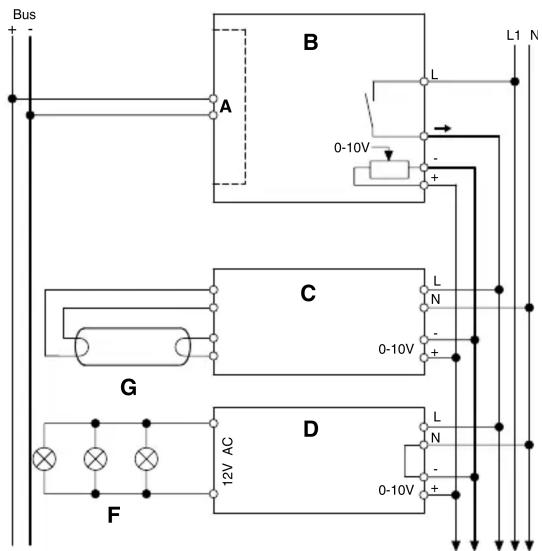
E
ABus coupler (built-in)
B Di mmer actuator for electronic ballasts (1-10V)
C El electronic ballast with 0-10V/1-10 V interface
D El electronic transformer with 0-10V/1-10 V control input
E To other devices with 0-10V/1-10 V interface
F LV hal ogen lamps
G FI fluorescent lamp
OPERATING AND DISPLAY ELEMENTS
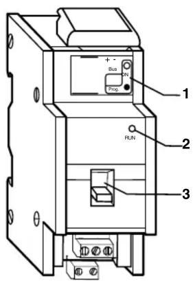
1 Programming button/Programming LED, red
2 Operating LED, green
3 Manual switch
HOW TO MOUNT THE CONTROL UNIT

Risk of fatal injury from electrical current.
During installation, the safety regulations specified in EN 50105 must be observed. The device may only be installed by skilled electricians. Otherwise, there is a risk of fire or electrocution.
The Dimmer actuator for electronic ballasts is a DIN rail mounted device and is mounted onto a DIN rail. A data rail is not required.
The bus connection is carried out via the bus connecting terminal supplied with the device.
The cable cover is then placed over the bus connecting terminal to guarantee the safety clearance of the bus cable to the 230 V cables. A maximum of four core pairs can be connected to the bus connecting terminal.
The cables are connected via terminals:
2 screw terminals for live conductors
1 screw terminal for switched live conductor
2 plug-in terminals for 0-10 V
The cables of the 0-10V/1-10 V control voltage can be connected to the terminals prior to installing the device and then inserted at a later date.

Caution!
Disconnect the mains voltage before connecting the device to the load.
Do not insert the terminal when it is under load.
All the devices that are mounted next to the control unit must at least be fitted with basic insulation. The green operating LED only lights up if the application program has been loaded correctly into the device.
The switch output (switched live conductor) can also be operated manually without bus voltage using the manual switch.
HOW TO PUT THE CONTROL UNIT INTO OPERATION

Risk of fatal injury:
All work carried out on the unit may only be performed by skilled electricians. Observe the regulations valid in the country of use, as well as the valid EIB directives.
1 Load the physical address into the device from the ETS via EIB.
2 Make the configuration settings in ETS and transfer them.
TECHNICAL DATA
Power supply from the bus: DC 24 V / approx. 17.5 mA
Insulation voltages: AC 4 kV bus/mains voltage and bus / 0-10
V
AC 4 kV 0-10
V - mains voltage
Switch contact: Make contact, floating
Connection data:
Nominal current: 16 A; inductive load at cos φ = 0.6
Incandescent lamps: 3600 watt
Halogen lamps: 230 V AC 2500 watt
Halogen lamps (LV): max. 2000 W via electronic transformers (e. g. 14 MET S 105 W)
Fluorescent lamps: 3600 VA uncompensated
Capacitive load: 3600, 200 μF
Protection The switch contact must be protected by a series connected 16 A circuit-breaker.
Service life: > 50,000 switching cycles at nominal load 0-10V/1-10V
Interface: 0-10 V for dimming electronic ballasts, MET S transformers (can be set via parameters)
Loading capacity: max. 100 mA (max. 50 electronic ballasts; depending on electronic ballasts)
Min. control voltage: 0 V
Ambient temperature:
- Operation: -5 °C to +45 °C
- Storage: -25 °C to +55 °C
- Transport: -25 °C to +70 °C
- Max. humidity: 93 %
Environment
The device is designed for use at a height up to 2000 m above sea level.
Connections
- Bus: via two 1 mm pins for bus connecting terminal
- Live conductor and switch output: 3-gang screw terminals for max. 2.5 mm ^4
- 1-10 V output: 2-pole plug-in terminals with screw connection for max. 2.5 mm²
Type of protection: IP 20
EC directives: complies with low-voltage directive 73/23/EEC, complies with EMC directive 89/336/EEC
Dimensions: 90x45x65 mm (HxWxD)
Device width: 2,5 TE = 45 mm
Brand : Gewiss
Model : GW90746
Category : Motion detector