
GW90708 - Electrical automation Gewiss - Free user manual and instructions
Find the device manual for free GW90708 Gewiss in PDF.


| Product Type | Electrical Switch/Socket |
| Brand | Gewiss |
| Model | GW90708 |
| Color | White |
| Material | Thermoplastic |
| Rated Voltage | 250 V AC |
| Rated Current | 10 A |
| Mounting Type | Flush mounting |
| Number of Gangs | 1 |
| Protection Rating | IP20 |
| Operating Temperature | -5°C to 40°C |
| Dimensions (H x W x D) | 80 x 80 x 40 mm |
| Weight | 100 g |
| Certifications | CE, RoHS |
| Usage | Indoor residential and commercial |
| Cleaning Instructions | Wipe with a dry, soft cloth |
| Safety Precautions | Do not exceed rated load; installation by qualified electrician |
| Warranty | 2 years |
Frequently Asked Questions - GW90708 Gewiss
User questions about GW90708 Gewiss
0 question about this device. Answer the ones you know or ask your own.
Ask a new question about this device
Download the instructions for your Electrical automation in PDF format for free! Find your manual GW90708 - Gewiss and take your electronic device back in hand. On this page are published all the documents necessary for the use of your device. GW90708 by Gewiss.
USER MANUAL GW90708 Gewiss
flowchart
graph TD
    subgraph BL
        A["~ = SV DR"] --> B["BK"]
        B --> C["HL1"]
        D["~ = SV DR"] --> E["LK"]
        E --> F["TLN"]
        G["~ = SV DR"] --> H["TLN"]
        H --> I["..."]
        J["~ = SV DR"] --> K["TLN"]
    end
    subgraph HL2
        L["~ = SV DR"] --> M["LK"]
        M --> N["TLN"]
        O["~ = SV DR"] --> P["TLN"]
        P --> Q["..."]
        R["~ = SV DR"] --> S["TLN"]
        S --> T["..."]
        U["~ = SV DR"] --> V["TLN"]
    end
    B --> M
    E --> P
    M --> N
    N --> P
    style BL fill:#f9f,stroke:#333
    style HL1 fill:#ccf,stroke:#333
    style HL2 fill:#cfc,stroke:#333
This device is a product of the KNX-EIB System and complies with KNX directives.
Detailed technical knowledge obtained in KNX-EIB training courses is a prerequisite to proper understanding.
The functionality of this device depends on the software.
Detailed information on loadable software and attainable functionality as well as the software itself can be obtained from the manufacturer's product database.
Planning, installation and commissioning of the unit is effected by means of KNX-certified software.
An updated version of the product database and the technical descriptions are available in the Internet at www.gewiss.com.
WHAT YOU CAN DO WITH THE AREA/LINE COUPLER
The coupler connects two BUS KNX-EIB data lines and ensures the electrical separation of these lines from one another.
The definite functions of the device are defined by addressing and parameterization.
Line coupler LK:
Physical address X.0.0.
Connection of a main line (HL) with an area line (BL). Alternatively with or without filter function. The coupler belongs logically to the subordinate line.
Area coupler BK:
Physical address X.0.0.
Connection of a main line (HL) with an area line (BL). Alternatively with or without filter function. The coupler belongs logically to the subordinate line.
Amplifier V:
Physical address X.Y.Z.
Handing and repetition of telegrams on a line, no filter function.
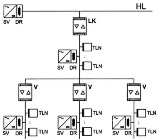
Division of a line into max. 4 independent line segments ≥ max. 3 line amplifiers connected in parallel per line (FIG. C). Each line segment requires a separate power supply (SV) including a choke (DR).
Schematics of a BUS KNX-EIB system
Use as area and line coupler (BK and LK)

flowchart
graph TD
    subgraph BL
        A["~ = SV DR"] --> B["BK"]
        B --> C["HL1"]
        D["~ = SV DR"] --> E["LK"]
        E --> F["TLN"]
        G["~ = SV DR"] --> H["TLN"]
        I["..."] --> J["TLN"]
    end
    subgraph HL2
        K["~ = SV DR"] --> L["LK"]
        L --> M["TLN"]
        N["~ = SV DR"] --> O["TLN"]
        P["..."] --> Q["TLN"]
    end
    A --> B
    D --> E
    G --> H
    I --> J
    K --> M
    L --> N
    M --> O
    N --> P
    O --> Q
Use as line coupler LK and amplifier V
flowchart
graph TD
    A["~ = SV DR"] --> B["LK"]
    B --> C["TLN"]
    B --> D["TLN"]
    C --> E["V"]
    D --> F["V"]
    E --> G["TLN"]
    F --> H["TLN"]
    G --> I["~ = SV DR"]
    H --> J["~ = SV DR"]
    I --> K["TLN"]
    J --> L["TLN"]
    K --> M["~ = SV DR"]
    L --> N["~ = SV DR"]
    M --> O["TLN"]
    N --> P["TLN"]
    O --> Q["HL"]
(TLN = bus subscriber, DR = choke, SV = KNX-EIB power supply). Each line requires a separate power supply.
CONTROL AND INDICATORS

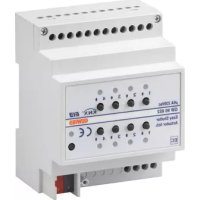
1 programming button
2 programming LED, red
3 operation LED, green
4 LED amber, incoming data on main line (HL)
5 LED amber, incoming data on subordinate line (UL)
6 diagnosis LED, red
7 connecting terminal for main line (HL)
8 connecting terminal for subordinate line (UL)
Function of diagnosis LED ("DIAG") red
LED off: telegrams are filtered or blocked (both directions)
LED on: telegrams are retransmitted without being filtered (at least one direction)
LED flashing: error detected (as per error flags in device)
Function of operation LED ("RUN") green
LED off: device off, no voltage on main line
LED on: device on, voltage on both lines
LED flashing: no voltage on subordinate line
HOW TO INSTALL THE AREA/LINE COUPLER
1 The device is snap-fastened on the DIN rail until the latch is heard to engage, with the connecting terminals pointing downloads
2 The main line is connected with the left-hand terminal (terminal "HL"). This terminal supplies power to the device electronics so that it is possible to report a bus voltage failure of the subordinate via the main line.
3 The subordinate line is connected to the right-hand terminal (terminal "UL").

Removal info: Do not lever out the connecting terminal from below.
Risk of shorting the bus voltage which is not available during the short-circuit.
HOW TO SET UP THE AREA/LINE COUPLER

Danger:
The device must be mounted and commissioned by an authorised electrician. The relevant guide lines, regulations and standards of the respective country.
1 Download the physical address in the device via ETS.
2 Set the parameters of the coupler and download them via ETS.
TECHNICAL DATA
Supply
BUS KNX-EIB: 21 - 30V dc from main line
Current consumption
main line: approx. 6 mA
subordinate line: approx. 8 mA
Connection: KNX-EIB BUS terminal for main and subordinate line
Fitting: snap-fastening on DIN rail
Ambient temperature: -5^+45^
Storage temperature: -25°C...+70°C
Type of protection: IP 20 in acc. with EN 60529
Safety class: III in acc. with EN 61140
Installation width: 36 mm (2 modules)
Weight: approx. 90 g
According to article 9 paragraph 2 of the European Directive 2004/108/EC, the responsible for placing the apparatus on the Community market is:
GEWISS S.p.A Via A. Volta, 1 - 24069 Cenate Sotto (BG) Italy Tel: +39 035 946 111 Fax: +39 035 945 270 E-mail: qualitymarks@gewiss.com


+39 035 946 111
8.30 - 12.30 / 14.00 - 18.00
- WHAT YOU CAN DO WITH THE AREA/LINE COUPLER
- Line coupler LK:
- Area coupler BK:
- Amplifier V:
- Schematics of a BUS KNX-EIB system
- Function of diagnosis LED ("DIAG") red
- Function of operation LED ("RUN") green
- HOW TO INSTALL THE AREA/LINE COUPLER
- HOW TO SET UP THE AREA/LINE COUPLER
- Danger:
- TECHNICAL DATA
- Supply
- Current consumption
Brand : Gewiss
Model : GW90708
Category : Electrical automation