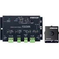
ANS501 - Capteur sonore Bogen - Free user manual and instructions
Find the device manual for free ANS501 Bogen in PDF.


| Product Type | Public Address Amplifier |
| Brand | Bogen |
| Model | ANS501 |
| Power Output (RMS) | 35 Watts @ 70V/100V |
| Frequency Response | 50 Hz – 20 kHz ±3 dB |
| Inputs | 3 Microphone (XLR) + 1 Line (RCA) |
| Outputs | 70V/100V speaker output, 4-16 ohm direct |
| Controls | Volume per channel, bass/treble, master volume |
| Priority Muting | Mic 1 priority over other inputs |
| Indicators | Power on, signal, clip/limit |
| Dimensions (H x W x D) | 3.5" x 19" x 10" (89 x 483 x 254 mm) |
| Rack Mountable | Yes, 2U rack space |
| Weight | 10.5 lbs (4.8 kg) |
| Power Supply | 120 V AC, 60 Hz (North America) |
| Construction | Steel chassis with black metal faceplate |
| Cooling | Convection (fanless) |
| Safety Certifications | UL, CE |
| Operating Temperature | 0°C to 40°C (32°F to 104°F) |
| Maintenance | Clean exterior with dry cloth; avoid liquids |
| Repair Information | Contact Bogen authorized service center; replace fuses as needed |
| Included Accessories | Power cord, rack ears, quick start guide |
Frequently Asked Questions - ANS501 Bogen
User questions about ANS501 Bogen
0 question about this device. Answer the ones you know or ask your own.
Ask a new question about this device
Download the instructions for your Capteur sonore in PDF format for free! Find your manual ANS501 - Bogen and take your electronic device back in hand. On this page are published all the documents necessary for the use of your device. ANS501 by Bogen.
USER MANUAL ANS501 Bogen
Ambient Noise Sensor Model ANS501
Installation and Use Manual
Notice
Every effort was made to ensure that the information in this guide was complete and accurate at the time of printing. However, information is subject to change.
Important Safety Information
WARNING: To Reduce The Risk of Fire Or Electric Shock, Do Not Expose This Apparatus To Rain Or Moisture.
Always follow these basic safety precautions when installing and using the unit:
- Read these instructions.
- Keep these instructions.
- Heed all warnings.
- Follow all instructions.
- Do not use this apparatus near water.
- Clean only with dry cloth.
- DO NOT block any ventilation openings. Install in accordance with the manufacturer's instructions.
- Do not install near any heat sources such as radiators, heat registers, stoves, or other apparatus (including amplifiers) that produce heat.
- Only use attachments/accessories specified by the manufacturer.
- Unplug this apparatus during lightning storms or when unused for long periods of time.
- Refer all servicing to qualified service personnel. Servicing is required when the apparatus has been damaged in any way, such as power supply cord or plug is damaged, liquid has been spilled or objects have fallen into the apparatus, the apparatus has been exposed to rain or moisture, does not operate normally, or has been dropped.
Domestic and International Listings
UL and CSA Listed
IMPORTANT
CAUTION
RISK OF ELECTRIC SHOCK DO NOT OPEN
CAUTION: TO PREVENT THE RISK OF ELECTRIC SHOCK, DO NOT REMOVE COVER (OR BACK). NO USER-SERVICEABLE PARTS INSIDE. REFER SERVICING TO QUALIFIED PERSONNEL.

The lightning flash with arrowhead symbol, within an equilateral triangle, is intended to alert the user to the presence of uninsulated “dangerous voltage” within the product’s enclosure that may be of sufficient magnitude to constitute a risk of electric shock to persons.

The exclamation point within an equilateral triangle is intended to alert the user to the presence of important operating and maintenance (servicing) instructions in the literature accompanying the appliance.
Contents
Page
DESCRIPTION 4
Package Contents 4
Features....4
PANEL DESCRIPTIONS....5
SENSOR MICROPHONE CONNECTIONS ....6
Sensor Microphone Wiring 6
Wiring Multiple Microphones 6
OPERATION 7-8
Front Panel Controls ....7
AUX Level Control 7
Relative Gain Control ....7
Ramp Speed Control 7
Maximum Boost Control 7
Threshold Controls 7
Front Panel Switches and Indicators....7
Mode Switch 7
Status LED 7
Power LED 7
Connections....8
Balanced Input 8
Unbalanced Input 8
Sensor MIC....8
Defeat Input 8
Balanced Output 8
Unbalanced Output....8
AUX Input 8
MODULE SETUP....9-12
Bypass Mode....9
Normal Mode 10
Bypass Mode Illustration ....11
Normal Mode Illustration 12
AMBIENT LEVEL SETTINGS....13
SPECIFICATIONS....13
BLOCK DIAGRAM 14
LIMITED WARRANTY 15
The Bogen Model ANS501 Ambient Noise Sensor is designed to electronically adjust the level of a page announcement or background music in an area of a building where ambient noise levels are continuously changing. It ensures that page announcements or background music are intelligible even during periods of high ambient noise levels.
The ANS501 monitors the ambient noise level through the use of an ANS500M sensor microphone module. Each sensor microphone module includes an adjustable mounting base for precise positioning.
One microphone and one power supply are included with the ANS501. Additional microphones may be purchased separately. The control unit is capable of supporting up to four (4) microphones wired in parallel. Wire runs between the control unit and microphones consist of two-conductor cable and can reach 2,000 feet (with 20AWG wire) with no appreciable loss of signal strength.
Package Contents
1 - ANS501
1 - ANS500M Sensor Microphone
1 - Power Supply
1 - Instruction Manual
Features
• Maximum boost control • Gain ramp speed control
- Activity threshold control • Relative gain control
- Ambient MIC input threshold control • Run/Set mode switch
• Balanced input/output • Unbalanced input/output
- Stereo unbalanced AUX inputs (summed mono) • AUX input level control
- Compact sensor microphone (one included) • AUX input bypasses gain control function
- Remote defeat connections • Connect up to 4 sensor microphones for large area coverage
- Bi-color status indicator LED • Power indicator LED

-
Aux Input - Mono summing, stereo, unbalanced RCA inputs on side panel.
-
AUX Level Control - Controls the AUX input level feed directly to the output.
-
Unbalanced Input - High-impedance unbalanced RCA input on side panel.
-
Balanced Input - High-impedance electronically balanced input (pluggable screw terminal).
-
Sensor MIC Input - Input connections for ANS500M sensor microphone(s) (pluggable screw terminal).
-
Defeat Input - The effects of the ANS501 will be defeated when these terminals are shorted together (pluggable screw terminal).
-
Balanced Output - Low-impedance electronically balanced output (pluggable screw terminal).
-
Unbalanced Output - Low-impedance unbalanced RCA output on side panel.
-
Maximum Boost - Sets the maximum signal gain for the ANS501.
-
Ramp Speed - Sets the speed by which signal gain is increased/decreased once the ambient noise level is above/below the threshold.
-
Power Connection - Barrel type power input connector on side panel.
-
Power LED - Green LED illuminates when power is present.
-
Status LED - Bi-color LED illuminates when different thresholds are triggered to assist in setup.
-
Ambient Threshold Control - Sets the ambient noise threshold level.
-
Activity Threshold - Sets reference level of typical audio program material applied to the unit.
-
Mode Switch - Facilitates setup of the module settings.
-
Relative Gain Control - Sets the difference between the ambient noise level and page level that the ANS501 will attempt to maintain.
Sensor Microphone Connections
Sensor Microphone Wiring
- The ANS501 requires connection of at least one sensor microphone for operation. To allow for better ambient noise sensing of large areas, up to 4 sensor microphones can be connected to a single ANS501.
- All microphones are wired in parallel matching the polarity markings on the sensor mic with the marking of the two MIC terminals on the ANS501.
- Wire runs between the control unit and microphones consist of two-conductor cable and can reach 2,000 feet (with 20AWG wire) with no appreciable loss of signal strength.

flowchart
graph TD
    A["BOGEN"] --> B["ANS501"]
    B --> C["RELATIVE GAIN"]
    B --> D["RAMP SPEED"]
    B --> E["MAX BOOST"]
    B --> F["RIAL OUT"]
    B --> G["UNBAL IN"]
    B --> H["UNBAL OUT"]
    I["POWER FOUNT"] --> B
    J["ALUX IN"] --> B
    K["MODE"] --> B
    L["SENSOR"] --> B
    M["MIC"] --> B
    N["DEEAT"] --> B
    O["BAL OUT"] --> B
    P["INSOL"] --> B
    Q["INSOL"] --> B
    R["INSOL"] --> B
    S["INSOL"] --> B
    T["INSOL"] --> B
    U["INSOL"] --> B
    V["INSOL"] --> B
    W["INSOL"] --> B
    X["INSOL"] --> B
    Y["INSOL"] --> B
    Z["INSOL"] --> B
    AA["INSOL"] --> B
    AB["INSOL"] --> B
    AC["INSOL"] --> B
    AD["INSOL"] --> B
    AE["INSOL"] --> B
    AF["INSOL"] --> B
    AG["INSOL"] --> B
    AH["INSOL"] --> B
    AI["INSOL"] --> B
    AJ["INSOL"] --> B
    AK["INSOL"] --> B
    AL["INSOL"] --> B
    AM["INSOL"] --> B
    AN["INSOL"] --> B
    AO["INSOL"] --> B
    AP["INSOL"] --> B
    AQ["INSOL"] --> B
    AR["INSOL"] --> B
    AS["INSOL"] --> B
    AT["INSOL"] --> B
    AU["INSOL"] --> B
    AV["INSOL"] --> B
    AW["INSOL"] --> B
    AX["INSOL"] --> B
    AY["ALUX IN"] --> AZ["ALUX LEVEL"]
    AZ --> BA["RIAL HIGH"]
    AZ --> BB["ACREY"]
    AZ --> BC["AMBIENT"]
    AZ --> BD["TIREFHOLD"]
    AZ --> BE["SINCHOR"]
    AZ --> BF["RANK"]
    AZ --> BG["RANGE"]
    AZ --> BH["RIME"]
    AZ --> BI["RISK"]
    AZ --> BJ["RISK"]
    AZ --> BK["RISK"]
    AZ --> BL["RISK"]
    AZ --> BM["RISK"]
    AZ --> BN["RISK"]
    AZ --> BO["RISK"]
    AZ --> BP["RISK"]
    AZ --> BQ["RISK"]
    AZ --> BR["RISK"]
    AZ --> BS["RISK"]
    AZ --> BT["RISK"]
    AZ --> BU["RISK"]
    AZ --> BV["RISK"]
    AZ --> BW["RISK"]
    AZ --> BX["RISK"]
    AZ --> BY["RISK"]
    AZ --> BZ["RISK"]
    AZ --> CA["RISK"]
    AZ --> CB["RISK"]
    AZ --> CC["RISK"]
    AZ --> CD["RISK"]
    AZ --> CE["RISK"]
    AZ --> CF["RISK"]
    AZ --> CG["RISK"]
    AZ --> CH["RISK"]
    AZ --> CI["RISK"]
    AZ --> CJ["RISK"]
    AZ --> CK["RISK"]
    AZ --> CL["RISK"]
    AZ --> CM["RISK"]
    AZ --> CN["RISK"]
    AZ --> CO["RISK"]
    AZ --> CP["RISK"]
    AZ --> CQ["RISK"]
    AZ --> CR["RISK"]
    AZ --> CS["RISK"]
    AZ --> CT["RISK"]
    AZ --> CU["RISK"]
    AZ --> CV["RISK"]
    AZ --> CW["RISK"]
    AZ --> CX["RISK"]
    AZ --> CY["RISK"]
    AZ --> CZ["RISK"]
    AZ --> DA["RISK"]
    AZ --> DB["RISK"]
    AZ --> DC["RISK"]
    AZ --> DD["RISK"]
    AZ --> DER["RISK"]
    AZ --> DF["RISK"]
    AZ --> DG["RISK"]
    AZ --> DH["RISK"]
    AZ --> DI["RISK"]
    AZ --> DJ["RISK"]
    AZ --> DK["RISK"]
    AZ --> DL["RISK"]
    AZ --> DV["RISK"]
    AZ --> DW["RISK"]
    AZ --> DX["RISK"]
    AZ --> DXR["RISK"]
Wiring Multiple Microphones
Physical connections can be made using either Home Runs back to the ANS501 from each sensor mic or by daisy-chaining sensor mics, depending on the installation. The maximum total wire length from any sensor mic to the ANS501 must be kept below 2000 ft.

flowchart
graph TD
    A["BOGEN"] -->|RUN TEST MODE| B["ANS501"]
    B -->|LOW HIGH ACTIVITY THRESHOLDS| C["AMBIENT"]
    B -->|AMBIENT STATUS| D["POWER"]
    B -->|RELATIVE GAIN| E["SENSOR"]
    B -->|RAMP SPEED 1.26| F["DEEAT"]
    B -->|MAX BOOST 1.22| G["BAL OUT"]
    B --> H["UNBAL IN"]
    H --> I["Ground"]
    B --> J["Ground"]
    J --> K["Total Max Wire Length 2000 ft."]
    K --> L["Three batteries with + and - polarity indicators"]
    L --> M["Ground"]
Home Run Style WiringDaisy Chain Style Wiring

flowchart
graph TD
    A["ANSS501 AMBIENT/NOISE SENSOR"] --> B["Input Module 1"]
    A --> C["Input Module 2"]
    A --> D["Input Module 3"]
    A --> E["Input Module 4"]
    A --> F["Input Module 5"]
    A --> G["Output Module 6"]
    A --> H["Output Module 7"]
    A --> I["Output Module 8"]
    A --> J["Output Module 9"]
    A --> K["Output Module 10"]
    A --> L["Output Module 11"]
    A --> M["Output Module 12"]
    A --> N["Output Module 13"]
    A --> O["Output Module 14"]
    A --> P["Output Module 15"]
    A --> Q["Output Module 16"]
    A --> R["Output Module 17"]
    A --> S["Output Module 18"]
    A --> T["Output Module 19"]
    A --> U["Output Module 20"]
    A --> V["Output Module 21"]
    A --> W["Output Module 22"]
    A --> X["Output Module 23"]
    A --> Y["Output Module 24"]
    A --> Z["Output Module 25"]
    A --> AA["Output Module 26"]
    A --> AB["Output Module 27"]
    A --> AC["Output Module 28"]
    A --> AD["Output Module 29"]
    A --> AE["Output Module 30"]
    A --> AF["Output Module 31"]
    A --> AG["Output Module 32"]
    A --> AH["Output Module 33"]
    A --> AI["Output Module 34"]
    A --> AJ["Output Module 35"]
    A --> AK["Output Module 36"]
    A --> AL["Output Module 37"]
    A --> AM["Output Module 38"]
    A --> AN["Output Module 39"]
    A --> AO["Output Module 40"]
    A --> AP["Output Module 41"]
    A --> AQ["Output Module 42"]
    A --> AR["Output Module 43"]
    A --> AS["Output Module 44"]
    A --> AT["Output Module 45"]
    A --> AU["Output Module 46"]
    A --> AV["Output Module 47"]
    A --> AW["Output Module 48"]
    A --> AX["Output Module 49"]
    A --> AY["Output Module 50"]
    A --> AZ["Max Run Length 2000 ft. (Each Run)"]
    style A fill:#f9f,stroke:#333,stroke-width:2px
    style B fill:#ccf,stroke:#333,stroke-width:2px
    style C fill:#ccf,stroke:#333,stroke-width:2px
    style D fill:#ccf,stroke:#333,stroke-width:2px
    style E fill:#ccf,stroke:#333,stroke-width:2px
    style F fill:#ccf,stroke:#333,stroke-width:2px
    style G fill:#ccf,stroke:#333,stroke-width:2px
    style H fill:#ccf,stroke:#333,stroke-width:2px
    style I fill:#ccf,stroke:#333,stroke-width:2px
    style J fill:#ccf,stroke:#333,stroke-width:2px
    style K fill:#ccf,stroke:#333,stroke-width:2px
    style L fill:#ccf,stroke:#333,stroke-width:2px
    style M fill:#ccf,stroke:#333,stroke-width:2px
    style N fill:#ccf,stroke:#333,stroke-width:2px
    style O fill:#ccf,stroke:#333,stroke-width:2px
    style P fill:#ccf,stroke:#333,stroke-width:2px
    style Q fill:#ccf,stroke:#333,stroke-width:2px
    style R fill:#ccf,stroke:#333,stroke-width:2px
    style S fill:#ccf,stroke:#333,stroke-width:2px
    style T fill:#ccf,stroke:#333,stroke-width:2px
    style U fill:#ccf,stroke:#333,stroke-width:2px
    style V fill:#ccf,stroke:#333,stroke-width:2px
    style W fill:#ccf,stroke:#333,stroke-width:2px
    style X fill:#ccf,stroke:#333,stroke-width:2px
    style Y fill:#ccf,stroke:#333,stroke-width:2px
    style Z fill:#ccf,stroke:#333,stroke-width:2px
Front Panel Controls
AUX Level Control
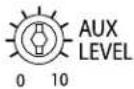
Controls the AUX input level, which is bussed directly to the output. Aux signal bypasses gain riding.
Relative Gain Control

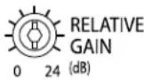
Sets the relative amount of gain maintained above the ambient level. Range is 1 dB to 24 dB of gain.
Ramp Speed Control
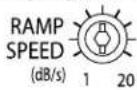
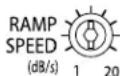
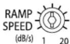
Sets the speed by which gain is increased/decreased to the signal once the ambient noise level is above/below the threshold, from less than 1 dB/s (slow) to greater than 20 dB/s (fast).
Maximum Boost Control
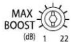
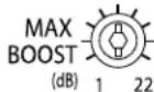
Sets the maximum amount of gain. Range is 1 dB to 22 dB of gain.
Threshold Controls
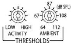
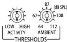
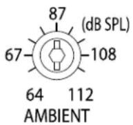
Activity threshold is set just above typical operating level of the program material applied to the gain processing stage of the ANS501. Ambient threshold adjusts the ambient noise input threshold from 64 dBspl to 112 dBspl.
Front Panel Switches and Indicators
Mode Switch

The Mode switch can be set to "Run" (for normal operation) or "Set"(for set up).
Status LED

Bi-color LED illuminates when different thresholds are triggered to assist in setup. Green indicates "+" gain. Amber indicates "-" gain.
Power LED

Green LED that illuminates when power is present.
Connections
Balanced Input

Unbalanced Input

Sensor MIC

Defeat Input

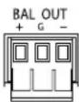
Balanced Output
Unbalanced Output
AUX Input

High-impedance, electronically balanced, pluggable screw terminal input. Signal gain responds to ambient noise changes.
High-impedance unbalanced RCA input. Signal gain responds to ambient noise changes.
Connections to ANS500M sensor microphone(s) are made here. The input is a pluggable screw terminal input.
The effects of the ANS501 will be defeated when these terminals are shorted together. The input is a pluggable screw terminal input.
Low-impedance electronically balanced, pluggable screw terminal output. Signal gain responds to ambient noise changes.
Low-impedance unbalanced RCA output. Signal gain responds to ambient noise changes.
Mono summing, stereo, unbalanced RCA inputs. This input bypasses the gain adjustment process of ANS501 and is fed directly to the output, via the AUX level control.
All inputs (balanced and unbalanced) into the ANS501, with the exception of the Aux input, will be affected by the automatic gain adjustments of the ANS501.
In audio systems that provide continuous background music, it may be desirable to have the background music stay at a fixed level but have all other source inputs (like a paging microphone) change level in response to the ambient noise level in an area. Background music is typically provided to make a venue seem less empty during slow periods or to help mask conversation during quiet times. It is often undesirable to have the background music level increase as ambient noise increases since it only adds to the overall noise in the area. The ANS501 provides an Aux input that bypasses the gain adjustment process so that it does not change with ambient noise levels.
Bypass Mode
Background music bypasses the gain adjustment process. Refer to page 11 for illustration.
Start with all POTS turned fully clockwise (except AUX LEVEL, which should be fully counterclockwise).



-
Connect the background music source to the ANS501's RCA Aux IN jacks.
-
Set the background music to the desired operating level using the AUX LEVEL control.
-
Set MODE Switch to "SET" mode.
-
Set RELATIVE GAIN to the desired amount of signal gain you would like the balanced/unbalanced input to ride over the ambient level.
-
Set MAX BOOST to limit the maximum amount of signal gain for the whole system.
-
Adjust AMBIENT THRESHOLD until the STATUS LED starts flashing amber, then adjust ACTIVITY THRESHOLD until amber stops flashing.
7a. Using the chart and diagram on page 13, set the AMBIENT THRESHOLD to the dBspl level where automatic increases to the system volume would be desired, then set the MODE Switch to the 'Run' position. - or -
7b. If the live ambient noise level (while making these adjustments) is at the desired trip point, set the MODE Switch to the 'Run' position, and then adjust the AMBIENT THRESHOLD control to a point where the STATUS LED flashes green.
-
Adjust RAMP SPEED to desired settings.
-
Test the system's response to noise and, if necessary, set the ACTIVITY THRESHOLD control higher if the maximum signal level is not achieved. Tweaking adjustments to MAX BOOST, RELATIVE GAIN, and RAMP SPEED controls may also be necessary.
Normal Mode
All sources are affected by the gain adjustment process. Background music source will need to be routed through the main mixer inputs, which will be affected by the gain adjustment process. Refer to page 12 for illustration.
Start with all POTS turned fully clockwise (AUX IN is not used in this mode).

-
Set MODE Switch to "SET" mode.
-
Set RELATIVE GAIN to the desired amount of signal gain you would like the balanced/unbalanced input to ride over the ambient level.
-
Set MAX BOOST to limit the maximum amount of signal gain for the whole system.
-
Adjust AMBIENT THRESHOLD until the STATUS LED starts flashing amber, then adjust ACTIVITY THRESHOLD until amber stops flashing.


5a. Using the chart and diagram on page 13, set the AMBIENT THRESHOLD to the dBspl level where automatic increases to the system volume would be desired, then set the MODE Switch to 'Run'. - or -
5b. If the live ambient noise level (while making these adjustments) is at the desired trip point, set the MODE Switch to the 'Run' position, and then adjust the AMBIENT THRESHOLD control to a point where the STATUS LED flashes green.
-
Adjust RAMP SPEED to desired settings.
-
Test the system's response to noise and, if necessary, set the ACTIVITY THRESHOLD control higher if the maximum signal level is not achieved. Tweaking adjustments to MAX BOOST, RELATIVE GAIN, and RAMP SPEED controls may also be necessary.

Bypass Mode Illustration
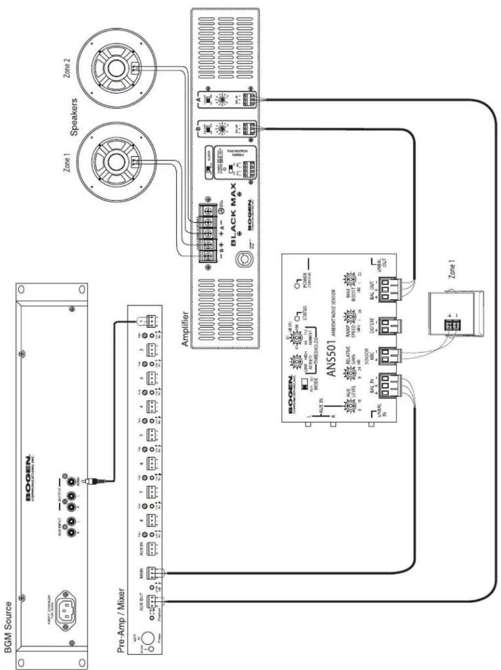
Normal Mode Illustration
Use this table to estimate the general dBspl level of the area's ambient noise if actual measurements are not available.
| Typical Ambient Noise Level Typical Environments | |||
| Very High Noise 85-95 dB | Speech Almost Impossible | Contraction SiteMachine ShopNoisy ManufacturingPrinting Shop | |
| High Noise 75-85 dB | Speech is Difficult | Assembly LineSupermarketTransportation Waiting RoomShipping/Warehouse | |
| Medium Noise 65-75 dB | Must Raise Voice to be Heard | Noisy OfficeRestaurantDepartment StoreBank / Public Area | |
| Low Noise 55-65 dB Speech is Easy | Doctor's OfficeHotel LobbyHospitalQuiet Office | ||
Specifications
Gain (Boost): 0 dB to 22 dB ( ± 1 dB)
Frequency Response: 5 Hz to 80 kHz (+0 / -3 dB)
S/N (20 Hz - 20 kHz): -96 dBV
Distortion: <0.007%
Input Impedance: Aux Input: Unbalanced 10 k-ohms
Unbalanced Input: 20 k-ohms
Balanced Input: 20 k-ohms
Output Impedance: Unbalanced Output: 300 ohms
Balanced Output: 600 ohms
Gain Ramp Speed: 1 dB/s to 20 dB/s
Power: 12 V AC/0.4A
Controls: Maximum Boost, Ramp Speed, Activity Threshold, Ambient Threshold, Aux Level, & Relative Gain
Connector: RCA types & pluggable screw terminals
Weight: 12 oz.
Dimensions: 5-1/4" W x 3" H x 1-1/4" D
Indicators: Bi-Color Status (Amber/Green); Power (Green)

flowchart
graph TD
    L["Input L"] --> SUMMING_BUFFER
    R["Input R"] --> SUMMING_BUFFER
    SUMMING_BUFFER --> AUX_LEVEL
    AUX_LEVEL --> GAIN_CONTROLLER["GAIN CONTROLLER"]
    GAIN_CONTROLLER --> ACTIVITY_THRESHOLD
    ACTIVITY_THRESHOLD --> SENSOR MIC
    SENSOR MIC --> S["+/-"]
    S --> DEFEAT
    DEFEAT --> RAMP_SPEED["RAMP SPEED"]
    DEFEAT --> MAX_BOOST["MAX_BOOST"]
    DEFEAT --> RELATIVE_GAIN["RELATIVE GAIN"]
    DEFEAT --> MODE["MODE/MODE"]
    SUMMING_BUFFER --> STATUS
    SUMMING_BUFFER --> AMBIENT_THRESHOLD["AMBIENT THRESHOLD"]
    AUX_LEVEL --> GAIN_CONTROLLER
    GAIN_CONTROLLER --> UNBALANCED_OUT["UNBALANCED OUT"]
    GAIN_CONTROLLER --> UNBALANCED_IN["UNBALANCED IN"]
    UNBALANCED_OUT --> G_BALANCED_OUT["G BALANCED OUT"]
    UNBALANCED_IN --> G_BALANCED_IN["G BALANCED IN"]
LIMITED WARRANTY; EXCLUSION OF CERTAIN DAMAGES
The Bogen ANS501 Ambient Noise Sensor is warranted to be free from defects in material and workmanship for two (2) years from the date of sale to the original purchaser. Any part of the product covered by this warranty that, with normal installation and use, becomes defective (as confirmed by Bogen upon inspection) during the applicable warranty period, will be repaired or replaced by Bogen, at Bogen's option, provided the product is shipped insured and prepaid to: Bogen Factory Service Department, 4570 Shelby Air Drive, Suite 11, Memphis, TN 38118 USA. Repaired or replacement product will be returned to you freight prepaid. This warranty does not extend to any of our products that have been subjected to abuse, misuse, improper storage, neglect, accident, improper installation or have been modified or repaired or altered in any manner whatsoever, or where the serial number or date code has been removed or defaced.
THE FOREGOING LIMITED WARRANTY IS BOGEN'S SOLE AND EXCLUSIVE WARRANTY AND THE PURCHASER'S SOLE AND EXCLUSIVE REMEDY. BOGEN MAKES NO OTHER WARRANTIES OF ANY KIND, EITHER EXPRESS OR IMPLIED, AND ALL IMPLIED WARRANTIES OF MERCHANTABILITY OR FITNESS FOR A PARTICULAR PURPOSE ARE HEREBY DISCLAIMED AND EXCLUDED TO THE MAXIMUM EXTENT ALLOWABLE BY LAW. Bogen's liability arising out of the manufacture, sale or supplying of products or their use or disposition, whether based upon warranty, contract, tort or otherwise, shall be limited to the price of the product. IN NO EVENT SHALL BOGEN BE LIABLE FOR SPECIAL, INCIDENTAL OR CONSEQUENTIAL DAMAGES (INCLUDING, BUT NOT LIMITED TO, LOSS OF PROFITS, LOSS OF DATA OR LOSS OF USE DAMAGES) ARISING OUT OF THE MANUFACTURE, SALE OR SUPPLYING OF PRODUCTS, EVEN IF BOGEN HAS BEEN ADVISED OF THE POSSIBILITY OF SUCH DAMAGES OR LOSSES. Some States do not allow the exclusion or limitation of incidental or consequential damages, so the above limitation or exclusion may not apply to you. This warranty gives you specific legal rights, and you may also have other rights which vary from State to State.
Products that are out of warranty will also be repaired by the Bogen Factory Service Department – same address as above or call 201-934-8500. The parts and labor involved in these repairs are warranted for 90 days when repaired by the Bogen Factory Service Department. All shipping charges in addition to parts and labor charges will be at the owner's expense. All returns require a Return Authorization number. For most efficient warranty or repair service, please include a description of the failure.
11/2014
- Ambient Noise Sensor Model ANS501
- Notice
- Important Safety Information
- Domestic and International Listings
- IMPORTANT
- CAUTION
- RISK OF ELECTRIC SHOCK DO NOT OPEN
- Contents
- DESCRIPTION 4
- PANEL DESCRIPTIONS....5
- SENSOR MICROPHONE CONNECTIONS ....6
- OPERATION 7-8
- MODULE SETUP....9-12
- AMBIENT LEVEL SETTINGS....13
- SPECIFICATIONS....13
- BLOCK DIAGRAM 14
- LIMITED WARRANTY 15
- Package Contents
- Features
- Sensor Microphone Connections
- Sensor Microphone Wiring
- Wiring Multiple Microphones
- Front Panel Controls
- Front Panel Switches and Indicators
- Connections
- Balanced Input
- Unbalanced Input
- Sensor MIC
- Defeat Input
- Balanced Output
- Unbalanced Output
- AUX Input
- Bypass Mode
- Normal Mode
- Specifications
- LIMITED WARRANTY; EXCLUSION OF CERTAIN DAMAGES
Brand : Bogen
Model : ANS501
Category : Capteur sonore